JP2017229148A - 電動式直動アクチュエータ - Google Patents
電動式直動アクチュエータ Download PDFInfo
- Publication number
- JP2017229148A JP2017229148A JP2016123138A JP2016123138A JP2017229148A JP 2017229148 A JP2017229148 A JP 2017229148A JP 2016123138 A JP2016123138 A JP 2016123138A JP 2016123138 A JP2016123138 A JP 2016123138A JP 2017229148 A JP2017229148 A JP 2017229148A
- Authority
- JP
- Japan
- Prior art keywords
- electric
- electric motor
- output shaft
- linear motion
- rotation
- Prior art date
- Legal status (The legal status is an assumption and is not a legal conclusion. Google has not performed a legal analysis and makes no representation as to the accuracy of the status listed.)
- Granted
Links
- 230000007246 mechanism Effects 0.000 claims abstract description 64
- 230000004907 flux Effects 0.000 claims abstract description 11
- 230000033001 locomotion Effects 0.000 claims description 83
- 230000002093 peripheral effect Effects 0.000 claims description 25
- 230000000452 restraining effect Effects 0.000 claims description 13
- 230000000903 blocking effect Effects 0.000 claims description 4
- 238000002788 crimping Methods 0.000 claims description 2
- 230000005284 excitation Effects 0.000 description 10
- 125000006850 spacer group Chemical group 0.000 description 10
- 239000000696 magnetic material Substances 0.000 description 6
- 238000005192 partition Methods 0.000 description 6
- 238000006243 chemical reaction Methods 0.000 description 5
- 239000003638 chemical reducing agent Substances 0.000 description 4
- 210000000078 claw Anatomy 0.000 description 4
- 238000003780 insertion Methods 0.000 description 4
- 230000037431 insertion Effects 0.000 description 4
- 230000004044 response Effects 0.000 description 4
- 229910000576 Laminated steel Inorganic materials 0.000 description 3
- 230000009467 reduction Effects 0.000 description 3
- 230000001360 synchronised effect Effects 0.000 description 3
- 239000000428 dust Substances 0.000 description 2
- 230000000694 effects Effects 0.000 description 2
- 238000000034 method Methods 0.000 description 2
- 230000000149 penetrating effect Effects 0.000 description 2
- 238000003860 storage Methods 0.000 description 2
- 238000003466 welding Methods 0.000 description 2
- RYGMFSIKBFXOCR-UHFFFAOYSA-N Copper Chemical compound [Cu] RYGMFSIKBFXOCR-UHFFFAOYSA-N 0.000 description 1
- XEEYBQQBJWHFJM-UHFFFAOYSA-N Iron Chemical group [Fe] XEEYBQQBJWHFJM-UHFFFAOYSA-N 0.000 description 1
- 229910052802 copper Inorganic materials 0.000 description 1
- 239000010949 copper Substances 0.000 description 1
- 238000005520 cutting process Methods 0.000 description 1
- 239000002783 friction material Substances 0.000 description 1
- 230000001771 impaired effect Effects 0.000 description 1
- 239000000463 material Substances 0.000 description 1
- 238000012986 modification Methods 0.000 description 1
- 230000004048 modification Effects 0.000 description 1
- 238000003825 pressing Methods 0.000 description 1
- 230000002265 prevention Effects 0.000 description 1
- 239000011347 resin Substances 0.000 description 1
- 229920005989 resin Polymers 0.000 description 1
- 229910001220 stainless steel Inorganic materials 0.000 description 1
- 239000010935 stainless steel Substances 0.000 description 1
Images


Classifications
-
- H—ELECTRICITY
- H02—GENERATION; CONVERSION OR DISTRIBUTION OF ELECTRIC POWER
- H02K—DYNAMO-ELECTRIC MACHINES
- H02K7/00—Arrangements for handling mechanical energy structurally associated with dynamo-electric machines, e.g. structural association with mechanical driving motors or auxiliary dynamo-electric machines
- H02K7/06—Means for converting reciprocating motion into rotary motion or vice versa
-
- F—MECHANICAL ENGINEERING; LIGHTING; HEATING; WEAPONS; BLASTING
- F16—ENGINEERING ELEMENTS AND UNITS; GENERAL MEASURES FOR PRODUCING AND MAINTAINING EFFECTIVE FUNCTIONING OF MACHINES OR INSTALLATIONS; THERMAL INSULATION IN GENERAL
- F16D—COUPLINGS FOR TRANSMITTING ROTATION; CLUTCHES; BRAKES
- F16D65/00—Parts or details
- F16D65/14—Actuating mechanisms for brakes; Means for initiating operation at a predetermined position
- F16D65/16—Actuating mechanisms for brakes; Means for initiating operation at a predetermined position arranged in or on the brake
- F16D65/18—Actuating mechanisms for brakes; Means for initiating operation at a predetermined position arranged in or on the brake adapted for drawing members together, e.g. for disc brakes
-
- F—MECHANICAL ENGINEERING; LIGHTING; HEATING; WEAPONS; BLASTING
- F16—ENGINEERING ELEMENTS AND UNITS; GENERAL MEASURES FOR PRODUCING AND MAINTAINING EFFECTIVE FUNCTIONING OF MACHINES OR INSTALLATIONS; THERMAL INSULATION IN GENERAL
- F16H—GEARING
- F16H25/00—Gearings comprising primarily only cams, cam-followers and screw-and-nut mechanisms
- F16H25/18—Gearings comprising primarily only cams, cam-followers and screw-and-nut mechanisms for conveying or interconverting oscillating or reciprocating motions
- F16H25/20—Screw mechanisms
- F16H25/2015—Means specially adapted for stopping actuators in the end position; Position sensing means
-
- H—ELECTRICITY
- H02—GENERATION; CONVERSION OR DISTRIBUTION OF ELECTRIC POWER
- H02K—DYNAMO-ELECTRIC MACHINES
- H02K1/00—Details of the magnetic circuit
- H02K1/06—Details of the magnetic circuit characterised by the shape, form or construction
- H02K1/22—Rotating parts of the magnetic circuit
- H02K1/27—Rotor cores with permanent magnets
- H02K1/2793—Rotors axially facing stators
- H02K1/2795—Rotors axially facing stators the rotor consisting of two or more circumferentially positioned magnets
- H02K1/2796—Rotors axially facing stators the rotor consisting of two or more circumferentially positioned magnets where both axial sides of the rotor face a stator
-
- H—ELECTRICITY
- H02—GENERATION; CONVERSION OR DISTRIBUTION OF ELECTRIC POWER
- H02K—DYNAMO-ELECTRIC MACHINES
- H02K21/00—Synchronous motors having permanent magnets; Synchronous generators having permanent magnets
- H02K21/12—Synchronous motors having permanent magnets; Synchronous generators having permanent magnets with stationary armatures and rotating magnets
- H02K21/24—Synchronous motors having permanent magnets; Synchronous generators having permanent magnets with stationary armatures and rotating magnets with magnets axially facing the armatures, e.g. hub-type cycle dynamos
-
- H—ELECTRICITY
- H02—GENERATION; CONVERSION OR DISTRIBUTION OF ELECTRIC POWER
- H02K—DYNAMO-ELECTRIC MACHINES
- H02K7/00—Arrangements for handling mechanical energy structurally associated with dynamo-electric machines, e.g. structural association with mechanical driving motors or auxiliary dynamo-electric machines
- H02K7/003—Couplings; Details of shafts
-
- F—MECHANICAL ENGINEERING; LIGHTING; HEATING; WEAPONS; BLASTING
- F16—ENGINEERING ELEMENTS AND UNITS; GENERAL MEASURES FOR PRODUCING AND MAINTAINING EFFECTIVE FUNCTIONING OF MACHINES OR INSTALLATIONS; THERMAL INSULATION IN GENERAL
- F16D—COUPLINGS FOR TRANSMITTING ROTATION; CLUTCHES; BRAKES
- F16D2121/00—Type of actuator operation force
- F16D2121/18—Electric or magnetic
- F16D2121/24—Electric or magnetic using motors
-
- H—ELECTRICITY
- H02—GENERATION; CONVERSION OR DISTRIBUTION OF ELECTRIC POWER
- H02K—DYNAMO-ELECTRIC MACHINES
- H02K7/00—Arrangements for handling mechanical energy structurally associated with dynamo-electric machines, e.g. structural association with mechanical driving motors or auxiliary dynamo-electric machines
- H02K7/10—Structural association with clutches, brakes, gears, pulleys or mechanical starters
- H02K7/102—Structural association with clutches, brakes, gears, pulleys or mechanical starters with friction brakes
Landscapes
- Engineering & Computer Science (AREA)
- Power Engineering (AREA)
- General Engineering & Computer Science (AREA)
- Mechanical Engineering (AREA)
- Connection Of Motors, Electrical Generators, Mechanical Devices, And The Like (AREA)
- Braking Arrangements (AREA)
Abstract
Description
1.直動部の外周に、この直動部と同軸に電動モータを配置した電動ディスクブレーキ装置(特許文献1)。
2.電動モータを直動機構の回転軸と異なる平行軸に配置した電動ブレーキ装置(特許文献2)。
3.8極9スロットのダブルステータ式のアキシアルギャップモータ(特許文献3)。
前記直動機構と前記電動モータとが、前記直動機構の前記回転入出力軸の軸心となる同一の軸心上に並んで配置され、
前記電動モータは、トルクに寄与する鎖交磁束を発生する磁極の向きが、前記電動モータにおける回転軸と平行となるように配置された固定子および回転子を備え、
前記電動モータの前記回転軸と前記回転入出力軸とが同一の部材または同心に連結される複数の部材から成る回転部材であり、前記ハウジングに対して前記回転部材が、前記回転軸における、軸方向および径方向について共通の拘束部によって保持されている。
前記拘束部は、
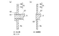
前記回転入出力軸の外周面に形成された環状溝とこの環状溝に嵌り込む止め輪、前記回転入出力軸の外周面に形成されたねじ部とこのねじ部に螺合されたナット、または、前記回転入出力軸の軸方向端部に形成された加締部を含むものとしても良い。
この場合、スラスト力に対する支持構造をより確実に簡素化し得る。
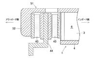
図1に示すように、この電動式直動アクチュエータ1は、電動モータ2と、直動機構3とを軸方向に直列に接続したアクチュエータである。この電動式直動アクチュエータ1は、電動モータ2と、直動機構3と、ハウジング4とを備える。この例の電動モータ2は、ダブルステータ型のアキシアルギャップモータである。直動機構3は、電動モータ2の回転運動を直進運動に変換する。ハウジング4は、直動機構3および電動モータ2を保持する。なお、簡略化のため配線等の一部構造は省略している。
電動モータ2は、トルクに寄与する鎖交磁束を発生する磁極の向きが、この電動モータ2における回転軸と平行となるように配置された固定子7および回転子8を備えた、いわゆるアキシアルギャップ型である。固定子7は、ハウジング4に対して静的に保持される。回転子8は、直動機構3の回転入出力軸5に対して静的に保持され、固定子7との鎖交磁束により回転トルクを発生する。回転子8は、この回転子8の軸方向の両面にそれぞれトルク発生面を有する界磁機構である。前記各「静的に」とは、すきま等の影響を除いて概ね運動が同期する(換言すれば、相対的に拘束された)関係を意味する。
図2に示すように、拘束部54は、回転子8と回転入出力軸5とを軸方向および径方向に拘束する機能を有する。図1に示すように、この拘束部54は、回転入出力軸5の外周面の両端部分に形成された環状溝55,55と、各環状溝55にそれぞれ嵌り込む止め輪56,56と、モータ間座57と、ラジアル軸受35と、軸受ケース32とを有する。
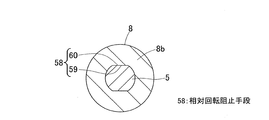
図2および図3に示すように、回転子8と回転入出力軸5とが円周方向に相対回転することを阻止する相対回転阻止手段58が設けられている。この相対回転阻止手段58は、例えば、回転子8の内周面の180度対向位置に互いに平行に形成された平面接触部59と、回転入出力軸5の外周面に形成され平面接触部59に結合される平面被接触部60とを有する。これら平面接触部59,平面被接触部60は、例えば、二面幅カット加工により形成される二面幅である。
図1に示すように、ハウジング4内における直動機構収容部4aに、直動機構3の大部分が組み込まれている。直動機構3は、電動モータ2の出力により、後述するブレーキロータに対して制動力を負荷する。この直動機構3は、電動モータ2の回転運動を回転入出力軸5を介して直動部6の直進運動に変換する。
直動機構収容部4aの内周面に、円筒状の直動部6が、回り止めされ且つ軸方向に移動自在に支持されている。直動部6の内周面には、径方向内方に突出し螺旋状に形成された螺旋突起が設けられている。この螺旋突起に複数の遊星ローラ39が噛合している。
以下の説明においては、各実施の形態で先行して説明している事項に対応している部分には同一の参照符号を付し、重複する説明を略する。構成の一部のみを説明している場合、構成の他の部分は、特に記載のない限り先行して説明している形態と同様とする。同一の構成から同一の作用効果を奏する。実施の各形態で具体的に説明している部分の組合せばかりではなく、特に組合せに支障が生じなければ、実施の形態同士を部分的に組合せることも可能である。
固定子7は、本図4のように軸方向に貫通する形状とする他、中間に磁性体から成るバックヨーク(図示せず)を配置し、そのバックヨークの両面に図示外のコイルを貼り合わせる形状とすることもできる。本構造を用いると、比較的省電力で高トルクを実現できる。
キャリパ51のうち、直動機構3の直動部6のアウトボード側端に、インボード側の摩擦パッド43が支持されている。この摩擦パッド43は、ブレーキロータ44のインボード側の側面と軸方向で対向する。電動式直動アクチュエータ1は、摩擦パッド43をブレーキロータ44に対して当接離隔させる駆動を行う。
回転子は、非磁性材料から成る保持部で永久磁石を保持すると、損失が少なく好適と考えられるが、磁性材から成る保持部で永久磁石を保持することもできる。回転子は、保持部を用いずに、複数の軸方向磁極に着磁された単一の磁石を、直接、回転入出力軸に固定する構造とすることもできる。
電動モータは、例えば、固定子に永久磁石、回転子にコイルおよびブラシ等を用いたDCモータの構成を採ることもでき、あるいは、回転子が回転することによって固定子インダクタンスが変化する形状の鉄心を用いたリラクタンスモータの構成を採ることもできる。
モータ角度を検出するセンサやサーミスタ、各電装系の配線部品など、電動式直動アクチュエータの適用に必要な構成は適宜設けられるものとする。
各実施形態の電動式直動アクチュエータを、電動ブレーキ装置以外の、例えば、プレス装置に適用することも可能である。
2…電動モータ
3…直動機構
4…ハウジング
5…回転入出力軸
6…直動部
7…固定子
8…回転子
53…回転部材
54…拘束部
55…環状溝
56…止め輪
58…相対回転阻止手段
61…ねじ部
62…ナット
63…加締部
Claims (5)
- 電動モータと、この電動モータの回転運動を回転入出力軸を介して直動部の直進運動に変換する直動機構と、この直動機構を保持するハウジングと、を備える電動式直動アクチュエータにおいて、
前記直動機構と前記電動モータとが、前記直動機構の前記回転入出力軸の軸心となる同一の軸心上に並んで配置され、
前記電動モータは、トルクに寄与する鎖交磁束を発生する磁極の向きが、前記電動モータにおける回転軸と平行となるように配置された固定子および回転子を備え、
前記電動モータの前記回転軸と前記回転入出力軸とが同一の部材または同心に連結される複数の部材から成る回転部材であり、前記ハウジングに対して前記回転部材が、前記回転軸における、軸方向および径方向について共通の拘束部によって保持された電動式直動アクチュエータ。 - 請求項1に記載の電動式直動アクチュエータにおいて、前記拘束部が、前記直動部と前記電動モータとの前記軸方向の中間に設けられた電動式直動アクチュエータ。
- 請求項1または請求項2に記載の電動式直動アクチュエータにおいて、前記拘束部は、前記回転子と前記回転入出力軸とを前記軸方向に拘束する機能を有し、前記拘束部が前記回転入出力軸に設けられている電動式直動アクチュエータ。
- 請求項3に記載の電動式直動アクチュエータにおいて、前記拘束部は、
前記回転入出力軸の外周面に形成された環状溝とこの環状溝に嵌り込む止め輪、前記回転入出力軸の外周面に形成されたねじ部とこのねじ部に螺合されたナット、または、前記回転入出力軸の軸方向端部に形成された加締部を含む電動式直動アクチュエータ。 - 請求項1ないし請求項4のいずれか1項に記載の電動式直動アクチュエータにおいて、前記回転子と前記回転入出力軸とが円周方向に相対回転することを阻止する相対回転阻止手段を備えた電動式直動アクチュエータ。
Priority Applications (5)
| Application Number | Priority Date | Filing Date | Title |
|---|---|---|---|
| JP2016123138A JP6779673B2 (ja) | 2016-06-22 | 2016-06-22 | 電動式直動アクチュエータ |
| PCT/JP2017/022385 WO2017221843A1 (ja) | 2016-06-22 | 2017-06-16 | 電動式直動アクチュエータ |
| CN201780038024.8A CN109417331B (zh) | 2016-06-22 | 2017-06-16 | 电动式直线移动促动器 |
| EP17815311.0A EP3477825A4 (en) | 2016-06-22 | 2017-06-16 | ELECTRIC LINEAR ACTUATOR |
| US16/225,430 US20190123616A1 (en) | 2016-06-22 | 2018-12-19 | Electric linear actuator |
Applications Claiming Priority (1)
| Application Number | Priority Date | Filing Date | Title |
|---|---|---|---|
| JP2016123138A JP6779673B2 (ja) | 2016-06-22 | 2016-06-22 | 電動式直動アクチュエータ |
Publications (2)
| Publication Number | Publication Date |
|---|---|
| JP2017229148A true JP2017229148A (ja) | 2017-12-28 |
| JP6779673B2 JP6779673B2 (ja) | 2020-11-04 |
Family
ID=60784107
Family Applications (1)
| Application Number | Title | Priority Date | Filing Date |
|---|---|---|---|
| JP2016123138A Expired - Fee Related JP6779673B2 (ja) | 2016-06-22 | 2016-06-22 | 電動式直動アクチュエータ |
Country Status (5)
| Country | Link |
|---|---|
| US (1) | US20190123616A1 (ja) |
| EP (1) | EP3477825A4 (ja) |
| JP (1) | JP6779673B2 (ja) |
| CN (1) | CN109417331B (ja) |
| WO (1) | WO2017221843A1 (ja) |
Cited By (2)
| Publication number | Priority date | Publication date | Assignee | Title |
|---|---|---|---|---|
| CN108736675A (zh) * | 2018-07-05 | 2018-11-02 | 中国科学院宁波材料技术与工程研究所 | 一种动圈式单极性永磁体旋转直线电机 |
| WO2019141738A1 (de) * | 2018-01-22 | 2019-07-25 | Logicdata Electronic & Software Entwicklungs Gmbh | Linearaktuator für ein möbelsystem, elektrisch verstellbares möbelsystem, einbauverfahren für einen linearaktuator in ein möbelsystem und möbelsystemanordnung |
Family Cites Families (15)
| Publication number | Priority date | Publication date | Assignee | Title |
|---|---|---|---|---|
| JPS52131110A (en) * | 1976-04-27 | 1977-11-02 | Matsushita Electric Works Ltd | Rotor of synchronous motor |
| JPS5822844U (ja) * | 1981-08-03 | 1983-02-12 | 株式会社東海理化電機製作所 | 直線出力型電動機 |
| JPS58117460A (ja) * | 1981-12-30 | 1983-07-13 | Sony Corp | 位置および速度の検出装置 |
| US6098479A (en) * | 1997-08-23 | 2000-08-08 | Hoermansdoerfer; Gerd | Linear actuator and preferred application |
| JP3716653B2 (ja) * | 1999-01-27 | 2005-11-16 | 日本精工株式会社 | リニアモータ |
| US6392322B1 (en) * | 2000-01-31 | 2002-05-21 | Precision Engine Controls Corporation | Rugged explosion-proof actuator with integral electronics |
| JP3750933B2 (ja) | 2002-02-22 | 2006-03-01 | 日信工業株式会社 | 電気式ディスクブレーキの配置構造 |
| JP4898123B2 (ja) * | 2005-01-13 | 2012-03-14 | Ntn株式会社 | 電動式直動アクチュエータおよび電動式ブレーキ装置 |
| JP5111863B2 (ja) | 2007-01-10 | 2013-01-09 | 本田技研工業株式会社 | アキシャルギャップ型モータおよび電動パワーステアリング装置 |
| TWI455458B (zh) * | 2007-09-20 | 2014-10-01 | Thk Co Ltd | 線性致動器 |
| FR2935029B1 (fr) * | 2008-08-12 | 2012-05-04 | Valeo Equip Electr Moteur | Demarreur comportant un arbre d'induit porte par un palier interpose entre un induit et un reducteur |
| JP2010270788A (ja) | 2009-05-19 | 2010-12-02 | Akebono Brake Ind Co Ltd | ディスクブレーキ |
| JP5069368B2 (ja) * | 2011-09-28 | 2012-11-07 | Ntn株式会社 | 電動式ブレーキ装置 |
| JP6076059B2 (ja) * | 2012-12-03 | 2017-02-08 | Ntn株式会社 | 車両用電動ブレーキ装置 |
| JP6710578B2 (ja) * | 2016-05-19 | 2020-06-17 | Ntn株式会社 | 電動式直動アクチュエータ |
-
2016
- 2016-06-22 JP JP2016123138A patent/JP6779673B2/ja not_active Expired - Fee Related
-
2017
- 2017-06-16 EP EP17815311.0A patent/EP3477825A4/en not_active Withdrawn
- 2017-06-16 WO PCT/JP2017/022385 patent/WO2017221843A1/ja unknown
- 2017-06-16 CN CN201780038024.8A patent/CN109417331B/zh active Active
-
2018
- 2018-12-19 US US16/225,430 patent/US20190123616A1/en not_active Abandoned
Cited By (3)
| Publication number | Priority date | Publication date | Assignee | Title |
|---|---|---|---|---|
| WO2019141738A1 (de) * | 2018-01-22 | 2019-07-25 | Logicdata Electronic & Software Entwicklungs Gmbh | Linearaktuator für ein möbelsystem, elektrisch verstellbares möbelsystem, einbauverfahren für einen linearaktuator in ein möbelsystem und möbelsystemanordnung |
| CN108736675A (zh) * | 2018-07-05 | 2018-11-02 | 中国科学院宁波材料技术与工程研究所 | 一种动圈式单极性永磁体旋转直线电机 |
| CN108736675B (zh) * | 2018-07-05 | 2023-11-14 | 中国科学院宁波材料技术与工程研究所 | 一种动圈式单极性永磁体旋转直线电机 |
Also Published As
| Publication number | Publication date |
|---|---|
| EP3477825A1 (en) | 2019-05-01 |
| US20190123616A1 (en) | 2019-04-25 |
| CN109417331A (zh) | 2019-03-01 |
| EP3477825A4 (en) | 2020-02-05 |
| WO2017221843A1 (ja) | 2017-12-28 |
| CN109417331B (zh) | 2021-07-09 |
| JP6779673B2 (ja) | 2020-11-04 |
Similar Documents
| Publication | Publication Date | Title |
|---|---|---|
| WO2018008709A1 (ja) | 電動式直動アクチュエータ | |
| JP6710578B2 (ja) | 電動式直動アクチュエータ | |
| US5982063A (en) | Electric motor with internal brake | |
| JP5205594B2 (ja) | 回転電機 | |
| WO2018038020A1 (ja) | 電動式直動アクチュエータ | |
| JP2008011599A (ja) | ブラシレスモータ | |
| US11060576B2 (en) | Electric linear motion actuator | |
| KR20140078819A (ko) | 모터 | |
| WO2017221843A1 (ja) | 電動式直動アクチュエータ | |
| WO2018034247A1 (ja) | 電動モータ装置 | |
| WO2019124543A1 (ja) | コアレスモータ | |
| WO2006118533A1 (en) | Releasable rotor | |
| WO2019123666A1 (ja) | コアレスモータ | |
| JP2008017588A (ja) | 駆動装置 | |
| JP2010017010A (ja) | アキシャルギャップ型モータ | |
| WO2013076788A1 (ja) | ブレーキ装置及び回転電機 | |
| JP2014057456A (ja) | 電動モータのロータ | |
| JP2023127999A (ja) | モータ及びそれを備える電動バイク | |
| JP2022079015A (ja) | ギヤモータ | |
| JP2004132468A (ja) | 電磁クラッチ・ブレーキ装置 | |
| JP2006304458A (ja) | 渦電流式減速装置 |
Legal Events
| Date | Code | Title | Description |
|---|---|---|---|
| A621 | Written request for application examination |
Free format text: JAPANESE INTERMEDIATE CODE: A621 Effective date: 20190528 |
|
| A131 | Notification of reasons for refusal |
Free format text: JAPANESE INTERMEDIATE CODE: A131 Effective date: 20200317 |
|
| A521 | Request for written amendment filed |
Free format text: JAPANESE INTERMEDIATE CODE: A523 Effective date: 20200420 |
|
| TRDD | Decision of grant or rejection written | ||
| A01 | Written decision to grant a patent or to grant a registration (utility model) |
Free format text: JAPANESE INTERMEDIATE CODE: A01 Effective date: 20200929 |
|
| A61 | First payment of annual fees (during grant procedure) |
Free format text: JAPANESE INTERMEDIATE CODE: A61 Effective date: 20201014 |
|
| R150 | Certificate of patent or registration of utility model |
Ref document number: 6779673 Country of ref document: JP Free format text: JAPANESE INTERMEDIATE CODE: R150 |
|
| LAPS | Cancellation because of no payment of annual fees |