JP2017229148A - Electric direct-acting actuator - Google Patents
Electric direct-acting actuator Download PDFInfo
- Publication number
- JP2017229148A JP2017229148A JP2016123138A JP2016123138A JP2017229148A JP 2017229148 A JP2017229148 A JP 2017229148A JP 2016123138 A JP2016123138 A JP 2016123138A JP 2016123138 A JP2016123138 A JP 2016123138A JP 2017229148 A JP2017229148 A JP 2017229148A
- Authority
- JP
- Japan
- Prior art keywords
- electric
- electric motor
- output shaft
- linear motion
- rotation
- Prior art date
- Legal status (The legal status is an assumption and is not a legal conclusion. Google has not performed a legal analysis and makes no representation as to the accuracy of the status listed.)
- Granted
Links
- 230000007246 mechanism Effects 0.000 claims abstract description 64
- 230000004907 flux Effects 0.000 claims abstract description 11
- 230000033001 locomotion Effects 0.000 claims description 83
- 230000002093 peripheral effect Effects 0.000 claims description 25
- 230000000452 restraining effect Effects 0.000 claims description 13
- 230000000903 blocking effect Effects 0.000 claims description 4
- 238000002788 crimping Methods 0.000 claims description 2
- 230000005284 excitation Effects 0.000 description 10
- 125000006850 spacer group Chemical group 0.000 description 10
- 239000000696 magnetic material Substances 0.000 description 6
- 238000005192 partition Methods 0.000 description 6
- 238000006243 chemical reaction Methods 0.000 description 5
- 239000003638 chemical reducing agent Substances 0.000 description 4
- 210000000078 claw Anatomy 0.000 description 4
- 238000003780 insertion Methods 0.000 description 4
- 230000037431 insertion Effects 0.000 description 4
- 230000004044 response Effects 0.000 description 4
- 229910000576 Laminated steel Inorganic materials 0.000 description 3
- 230000009467 reduction Effects 0.000 description 3
- 230000001360 synchronised effect Effects 0.000 description 3
- 239000000428 dust Substances 0.000 description 2
- 230000000694 effects Effects 0.000 description 2
- 238000000034 method Methods 0.000 description 2
- 230000000149 penetrating effect Effects 0.000 description 2
- 238000003860 storage Methods 0.000 description 2
- 238000003466 welding Methods 0.000 description 2
- RYGMFSIKBFXOCR-UHFFFAOYSA-N Copper Chemical compound [Cu] RYGMFSIKBFXOCR-UHFFFAOYSA-N 0.000 description 1
- XEEYBQQBJWHFJM-UHFFFAOYSA-N Iron Chemical group [Fe] XEEYBQQBJWHFJM-UHFFFAOYSA-N 0.000 description 1
- 229910052802 copper Inorganic materials 0.000 description 1
- 239000010949 copper Substances 0.000 description 1
- 238000005520 cutting process Methods 0.000 description 1
- 239000002783 friction material Substances 0.000 description 1
- 230000001771 impaired effect Effects 0.000 description 1
- 239000000463 material Substances 0.000 description 1
- 238000012986 modification Methods 0.000 description 1
- 230000004048 modification Effects 0.000 description 1
- 238000003825 pressing Methods 0.000 description 1
- 230000002265 prevention Effects 0.000 description 1
- 239000011347 resin Substances 0.000 description 1
- 229920005989 resin Polymers 0.000 description 1
- 229910001220 stainless steel Inorganic materials 0.000 description 1
- 239000010935 stainless steel Substances 0.000 description 1
Images


Classifications
-
- H—ELECTRICITY
- H02—GENERATION; CONVERSION OR DISTRIBUTION OF ELECTRIC POWER
- H02K—DYNAMO-ELECTRIC MACHINES
- H02K7/00—Arrangements for handling mechanical energy structurally associated with dynamo-electric machines, e.g. structural association with mechanical driving motors or auxiliary dynamo-electric machines
- H02K7/06—Means for converting reciprocating motion into rotary motion or vice versa
-
- F—MECHANICAL ENGINEERING; LIGHTING; HEATING; WEAPONS; BLASTING
- F16—ENGINEERING ELEMENTS AND UNITS; GENERAL MEASURES FOR PRODUCING AND MAINTAINING EFFECTIVE FUNCTIONING OF MACHINES OR INSTALLATIONS; THERMAL INSULATION IN GENERAL
- F16D—COUPLINGS FOR TRANSMITTING ROTATION; CLUTCHES; BRAKES
- F16D65/00—Parts or details
- F16D65/14—Actuating mechanisms for brakes; Means for initiating operation at a predetermined position
- F16D65/16—Actuating mechanisms for brakes; Means for initiating operation at a predetermined position arranged in or on the brake
- F16D65/18—Actuating mechanisms for brakes; Means for initiating operation at a predetermined position arranged in or on the brake adapted for drawing members together, e.g. for disc brakes
-
- F—MECHANICAL ENGINEERING; LIGHTING; HEATING; WEAPONS; BLASTING
- F16—ENGINEERING ELEMENTS AND UNITS; GENERAL MEASURES FOR PRODUCING AND MAINTAINING EFFECTIVE FUNCTIONING OF MACHINES OR INSTALLATIONS; THERMAL INSULATION IN GENERAL
- F16H—GEARING
- F16H25/00—Gearings comprising primarily only cams, cam-followers and screw-and-nut mechanisms
- F16H25/18—Gearings comprising primarily only cams, cam-followers and screw-and-nut mechanisms for conveying or interconverting oscillating or reciprocating motions
- F16H25/20—Screw mechanisms
- F16H25/2015—Means specially adapted for stopping actuators in the end position; Position sensing means
-
- H—ELECTRICITY
- H02—GENERATION; CONVERSION OR DISTRIBUTION OF ELECTRIC POWER
- H02K—DYNAMO-ELECTRIC MACHINES
- H02K1/00—Details of the magnetic circuit
- H02K1/06—Details of the magnetic circuit characterised by the shape, form or construction
- H02K1/22—Rotating parts of the magnetic circuit
- H02K1/27—Rotor cores with permanent magnets
- H02K1/2793—Rotors axially facing stators
- H02K1/2795—Rotors axially facing stators the rotor consisting of two or more circumferentially positioned magnets
- H02K1/2796—Rotors axially facing stators the rotor consisting of two or more circumferentially positioned magnets where both axial sides of the rotor face a stator
-
- H—ELECTRICITY
- H02—GENERATION; CONVERSION OR DISTRIBUTION OF ELECTRIC POWER
- H02K—DYNAMO-ELECTRIC MACHINES
- H02K21/00—Synchronous motors having permanent magnets; Synchronous generators having permanent magnets
- H02K21/12—Synchronous motors having permanent magnets; Synchronous generators having permanent magnets with stationary armatures and rotating magnets
- H02K21/24—Synchronous motors having permanent magnets; Synchronous generators having permanent magnets with stationary armatures and rotating magnets with magnets axially facing the armatures, e.g. hub-type cycle dynamos
-
- H—ELECTRICITY
- H02—GENERATION; CONVERSION OR DISTRIBUTION OF ELECTRIC POWER
- H02K—DYNAMO-ELECTRIC MACHINES
- H02K7/00—Arrangements for handling mechanical energy structurally associated with dynamo-electric machines, e.g. structural association with mechanical driving motors or auxiliary dynamo-electric machines
- H02K7/003—Couplings; Details of shafts
-
- F—MECHANICAL ENGINEERING; LIGHTING; HEATING; WEAPONS; BLASTING
- F16—ENGINEERING ELEMENTS AND UNITS; GENERAL MEASURES FOR PRODUCING AND MAINTAINING EFFECTIVE FUNCTIONING OF MACHINES OR INSTALLATIONS; THERMAL INSULATION IN GENERAL
- F16D—COUPLINGS FOR TRANSMITTING ROTATION; CLUTCHES; BRAKES
- F16D2121/00—Type of actuator operation force
- F16D2121/18—Electric or magnetic
- F16D2121/24—Electric or magnetic using motors
-
- H—ELECTRICITY
- H02—GENERATION; CONVERSION OR DISTRIBUTION OF ELECTRIC POWER
- H02K—DYNAMO-ELECTRIC MACHINES
- H02K7/00—Arrangements for handling mechanical energy structurally associated with dynamo-electric machines, e.g. structural association with mechanical driving motors or auxiliary dynamo-electric machines
- H02K7/10—Structural association with clutches, brakes, gears, pulleys or mechanical starters
- H02K7/102—Structural association with clutches, brakes, gears, pulleys or mechanical starters with friction brakes
Landscapes
- Engineering & Computer Science (AREA)
- Power Engineering (AREA)
- General Engineering & Computer Science (AREA)
- Mechanical Engineering (AREA)
- Connection Of Motors, Electrical Generators, Mechanical Devices, And The Like (AREA)
- Braking Arrangements (AREA)
Abstract
Description
この発明は、例えば、電動ブレーキ装置に適用される電動式直動アクチュエータに関する。 The present invention relates to, for example, an electric linear actuator applied to an electric brake device.
電動アクチュエータおよび電動モータとして、以下の技術が提案されている。
1.直動部の外周に、この直動部と同軸に電動モータを配置した電動ディスクブレーキ装置(特許文献1)。
2.電動モータを直動機構の回転軸と異なる平行軸に配置した電動ブレーキ装置(特許文献2)。
3.8極9スロットのダブルステータ式のアキシアルギャップモータ(特許文献3)。
The following techniques have been proposed as electric actuators and electric motors.
1. An electric disc brake device in which an electric motor is arranged coaxially with the linear motion part on the outer periphery of the linear motion part (Patent Document 1).
2. An electric brake device in which an electric motor is arranged on a parallel axis different from the rotation axis of the linear motion mechanism (Patent Document 2).
3. A 8-pole, 9-slot double stator type axial gap motor (Patent Document 3).
特許文献1〜2に記載のような電動式直動アクチュエータを用いた電動ブレーキ装置は、一般に車両への搭載スペースが極めて限られており、可能な限り省スペースで機能を実現する必要がある。また、例えばアンチロック ブレーキ システム(Antilock Brake System:略称ABS)に代表される車輪速制御等において、電動ブレーキには高速・高精度なブレーキ力制御が求められる。
In general, an electric brake device using an electric linear actuator as described in
例えば特許文献1のような、アクチュエータの外周に電動モータを配置する構造では、電動モータのロータ径が大きくなるため、慣性モーメントが増大し、応答性および制御精度を損なう場合がある。あるいは、ロータの回転に必要な運動エネルギーは慣性モーメントに比例するため、高速な応答を実現するために瞬時最大の消費電力が増大し、電力を供給する電源装置のコストが高くなる可能性がある。また、例えば電動ディスクブレーキ装置のような、アクチュエータの加圧対象物が摩擦パッドのように極めて高温になる場合、電動モータが熱源に近いため、耐久性が問題となる可能性がある。 For example, in a structure in which an electric motor is arranged on the outer periphery of an actuator as in Patent Document 1, since the rotor diameter of the electric motor increases, the moment of inertia increases, and the response and control accuracy may be impaired. Alternatively, since the kinetic energy necessary for rotating the rotor is proportional to the moment of inertia, the instantaneous maximum power consumption increases in order to achieve a high-speed response, which may increase the cost of the power supply device that supplies the power. . Further, when an object to be pressurized by an actuator becomes extremely hot like a friction pad, such as an electric disk brake device, durability may be a problem because the electric motor is close to a heat source.
例えば特許文献2のような、電動モータと直動アクチュエータとを平行に配置する場合、一般に電動モータおよび直動アクチュエータの外観は円筒形状となることが多い。この場合、二つの円筒が隣接するため、隙間に一定量のデッドスペースが生じてしまう場合がある。また電動モータと直動アクチュエータとの間に平行歯車のような連結機構が要求スペックによらず必要となり、コスト増となる可能性がある。その他、電動モータと直動アクチュエータそれぞれに支持構造が必要となるため、スペースおよびコストが問題になる場合がある。
For example, when an electric motor and a linear actuator are arranged in parallel as in
省スペースで高トルクを実現するモータ構造として、例えば特許文献3に示すようなアキシアルギャップ式同期モータが知られている。しかしながら、アキシアルギャップモータは一般にロータとステータ間のギャップ不均衡および磁気回路の不均衡などにより、回転軸方向に大きなスラスト力が発生し易い。このため、前記スラスト力に対する支持構造が複雑になり、コストが増加する場合がある。 As a motor structure that realizes high torque in a space-saving manner, for example, an axial gap type synchronous motor as shown in Patent Document 3 is known. However, the axial gap motor generally tends to generate a large thrust force in the direction of the rotation axis due to a gap imbalance between the rotor and the stator and a magnetic circuit imbalance. For this reason, the support structure for the thrust force is complicated, and the cost may increase.
この発明の目的は、省スペース化を図ると共に、スラスト力に対する支持構造を簡素化しコスト低減を図ることができる電動式直動アクチュエータを提供することである。 An object of the present invention is to provide an electric linear actuator that can save space, simplify a support structure against thrust force, and reduce costs.
この発明の電動式直動アクチュエータは、電動モータと、この電動モータの回転運動を回転入出力軸を介して直動部の直進運動に変換する直動機構と、この直動機構を保持するハウジングと、を備える電動式直動アクチュエータにおいて、
前記直動機構と前記電動モータとが、前記直動機構の前記回転入出力軸の軸心となる同一の軸心上に並んで配置され、
前記電動モータは、トルクに寄与する鎖交磁束を発生する磁極の向きが、前記電動モータにおける回転軸と平行となるように配置された固定子および回転子を備え、
前記電動モータの前記回転軸と前記回転入出力軸とが同一の部材または同心に連結される複数の部材から成る回転部材であり、前記ハウジングに対して前記回転部材が、前記回転軸における、軸方向および径方向について共通の拘束部によって保持されている。
An electric linear motion actuator according to the present invention includes an electric motor, a linear motion mechanism that converts the rotational motion of the electric motor into a linear motion of a linear motion portion via a rotation input / output shaft, and a housing that holds the linear motion mechanism In an electric linear actuator comprising:
The linear motion mechanism and the electric motor are arranged side by side on the same axis serving as the axis of the rotation input / output shaft of the linear motion mechanism,
The electric motor includes a stator and a rotor arranged such that the direction of the magnetic poles that generate the interlinkage magnetic flux contributing to the torque is parallel to the rotation axis of the electric motor,
The rotary shaft of the electric motor and the rotary input / output shaft are the same member or a rotary member composed of a plurality of members connected concentrically, and the rotary member is a shaft of the rotary shaft relative to the housing. It is hold | maintained by the common restraint part about a direction and radial direction.
この構成によると、電動モータは、トルクに寄与する鎖交磁束を発生する磁極の向きが、前記電動モータにおける回転軸と平行となるように配置された固定子および回転子を備えるいわゆるアキシアルギャップモータである。さらに直動機構と電動モータとが、直動機構の回転入出力軸の軸心となる同一の軸心上に並んで配置されている。このため、電動モータと直動アクチュエータとを平行に配置する構造等に比べて、無効なスペースが少なく省スペース化を図ることができ、且つ、慣性モーメントが小さく高応答な電動式直動アクチュエータを実現できる。 According to this configuration, the electric motor is a so-called axial gap motor including a stator and a rotor arranged such that the direction of the magnetic poles that generate the interlinkage magnetic flux that contributes to the torque is parallel to the rotation axis of the electric motor. It is. Further, the linear motion mechanism and the electric motor are arranged side by side on the same axis that is the axis of the rotation input / output shaft of the linear motion mechanism. Therefore, compared to a structure in which the electric motor and the direct acting actuator are arranged in parallel, an electric linear acting actuator that has a small amount of invalid space and can save space, and has a small moment of inertia and high response. realizable.
電動モータの回転軸と回転入出力軸とが同一の部材または同心に連結される複数の部材から成る回転部材であるため、減速機を削減可能となり特に径方向の省スペース化を図りつつ構造を簡素化することが可能となる。さらにハウジングに対して回転部材が、回転軸における、軸方向および径方向について共通の拘束部によって保持されているため、スラスト力に対する支持構造を簡素化し部品点数の低減を図ることができる。これにより省スペース化およびコスト低減を図ることができる。 Since the rotating shaft of the electric motor and the rotating input / output shaft are the same member or a rotating member consisting of a plurality of members connected concentrically, the speed reducer can be reduced, and the structure can be reduced while saving space in the radial direction. It becomes possible to simplify. Further, since the rotating member is held by the common restraining portion in the axial direction and the radial direction of the rotating shaft with respect to the housing, the support structure for the thrust force can be simplified and the number of parts can be reduced. Thereby, space saving and cost reduction can be achieved.
前記拘束部が、前記直動部と前記電動モータとの前記軸方向の中間に設けられても良い。この場合、例えば、同一のハウジング内に電動モータおよびアクチュエータを平行に配置する従来構造などと比べて、組立性の向上および直動機構などの汎用性の向上を図ることができる。 The restraint portion may be provided in the middle of the axial direction between the linear motion portion and the electric motor. In this case, for example, the assembling property and the versatility such as the linear motion mechanism can be improved as compared with the conventional structure in which the electric motor and the actuator are arranged in parallel in the same housing.
前記拘束部は、前記回転子と前記回転入出力軸とを前記軸方向に拘束する機能を有し、前記拘束部が前記回転入出力軸に設けられていても良い。
前記拘束部は、
前記回転入出力軸の外周面に形成された環状溝とこの環状溝に嵌り込む止め輪、前記回転入出力軸の外周面に形成されたねじ部とこのねじ部に螺合されたナット、または、前記回転入出力軸の軸方向端部に形成された加締部を含むものとしても良い。
この場合、スラスト力に対する支持構造をより確実に簡素化し得る。
The restricting portion may have a function of restricting the rotor and the rotation input / output shaft in the axial direction, and the restricting portion may be provided on the rotation input / output shaft.
The restraining portion is
An annular groove formed on the outer peripheral surface of the rotary input / output shaft and a retaining ring fitted into the annular groove, a screw portion formed on the outer peripheral surface of the rotary input / output shaft, and a nut screwed into the screw portion, or Further, it may include a crimping portion formed at an axial end portion of the rotation input / output shaft.
In this case, the support structure for the thrust force can be simplified more reliably.
前記回転子と前記回転入出力軸とが円周方向に相対回転することを阻止する相対回転阻止手段を備えても良い。この場合、回転子から回転入出力軸へのトルク伝達を可能とし得る。また、回転子と回転入出力軸とを一体に回転させることができ、例えば、モータとアクチュエータとの間に減速機を介在させた従来構造よりも、構造を簡素化することができ、省スペース化を図ることができる。 Relative rotation blocking means for blocking relative rotation of the rotor and the rotation input / output shaft in the circumferential direction may be provided. In this case, torque can be transmitted from the rotor to the rotation input / output shaft. In addition, the rotor and the rotation input / output shaft can be rotated integrally. For example, the structure can be simplified and space-saving compared to the conventional structure in which a speed reducer is interposed between the motor and the actuator. Can be achieved.
この発明の電動式直動アクチュエータは、電動モータと、この電動モータの回転運動を回転入出力軸を介して直動部の直進運動に変換する直動機構と、この直動機構を保持するハウジングと、を備える電動式直動アクチュエータにおいて、前記直動機構と前記電動モータとが、前記直動機構の前記回転入出力軸の軸心となる同一の軸心上に並んで配置され、前記電動モータは、トルクに寄与する鎖交磁束を発生する磁極の向きが、前記電動モータにおける回転軸と平行となるように配置された固定子および回転子を備え、前記電動モータの前記回転軸と前記回転入出力軸とが同一の部材または同心に連結される複数の部材から成る回転部材であり、前記ハウジングに対して前記回転部材が、前記回転軸における、軸方向および径方向について共通の拘束部によって保持された。このため、省スペース化を図ると共に、スラスト力に対する支持構造を簡素化しコスト低減を図ることができる。 An electric linear motion actuator according to the present invention includes an electric motor, a linear motion mechanism that converts the rotational motion of the electric motor into a linear motion of a linear motion portion via a rotation input / output shaft, and a housing that holds the linear motion mechanism The linear motion mechanism and the electric motor are arranged side by side on the same axis serving as the axis of the rotation input / output shaft of the linear motion mechanism, and the electric motor The motor includes a stator and a rotor arranged such that the direction of the magnetic poles that generate the interlinkage magnetic flux that contributes to the torque is parallel to the rotation shaft in the electric motor, and the rotation shaft of the electric motor and the rotor The rotating input / output shaft is a rotating member composed of the same member or a plurality of concentrically connected members, and the rotating member is in the axial direction and the radial direction of the rotating shaft with respect to the housing. It held by the restraint portion of the through. For this reason, while saving space, the support structure with respect to thrust force can be simplified and cost reduction can be aimed at.
この発明の実施形態に係る電動式直動アクチュエータを図1ないし図3と共に説明する。この電動式直動アクチュエータは、例えば、車両に搭載される電動ブレーキ装置(後述する)に適用される。
図1に示すように、この電動式直動アクチュエータ1は、電動モータ2と、直動機構3とを軸方向に直列に接続したアクチュエータである。この電動式直動アクチュエータ1は、電動モータ2と、直動機構3と、ハウジング4とを備える。この例の電動モータ2は、ダブルステータ型のアキシアルギャップモータである。直動機構3は、電動モータ2の回転運動を直進運動に変換する。ハウジング4は、直動機構3および電動モータ2を保持する。なお、簡略化のため配線等の一部構造は省略している。
An electric linear actuator according to an embodiment of the present invention will be described with reference to FIGS. This electric linear actuator is applied to, for example, an electric brake device (described later) mounted on a vehicle.
As shown in FIG. 1, the electric linear actuator 1 is an actuator in which an
電動モータ2について説明する。
電動モータ2は、トルクに寄与する鎖交磁束を発生する磁極の向きが、この電動モータ2における回転軸と平行となるように配置された固定子7および回転子8を備えた、いわゆるアキシアルギャップ型である。固定子7は、ハウジング4に対して静的に保持される。回転子8は、直動機構3の回転入出力軸5に対して静的に保持され、固定子7との鎖交磁束により回転トルクを発生する。回転子8は、この回転子8の軸方向の両面にそれぞれトルク発生面を有する界磁機構である。前記各「静的に」とは、すきま等の影響を除いて概ね運動が同期する(換言すれば、相対的に拘束された)関係を意味する。
The
The
円筒形状のハウジング4内に、電動モータ2が設けられている。ハウジング4内には、直動機構3の大部分を収容する直動機構収容部4aと、電動モータ2を収容するモータ収容部4bと、これら直動機構収容部4a,モータ収容部4bを仕切る隔壁4cとが設けられている。モータ収容部4bは、ハウジング4内における軸方向一端側に設けられ、直動機構収容部4aは、ハウジング4内における軸方向他端側に設けられている。
An
隔壁4cは、回転入出力軸5の軸方向に対して垂直に設けられ、直動機構収容部4aからモータ収容部4bへの回転入出力軸5の侵入を許す貫通孔が形成されている。ハウジング4のモータ収容部4bに電動モータ2が収容された状態で、ハウジング4における電動モータ2側の開口端を塞ぐモータカバー45が設けられている。
The
固定子7は、回転子8の軸方向の両面にそれぞれ配置される一対の励磁機構7A,7Bを備えている。これら励磁機構7A,7Bのうち、隔壁4c側に在る一方を第1の励磁機構7A、モータカバー45側に在る他方を第2の励磁機構7Bとする。第1の励磁機構7Aは、磁性体コア10A、バックヨーク9A、およびコイル11Aを有する。第2の励磁機構7Bは、磁性体コア10B、バックヨーク9B、およびコイル11Bを有する。
The
第1の励磁機構7Aについて説明すると、ハウジング4内のモータ収容部4bにおいて、隔壁4cに当接するようにバックヨーク9Aが設けられている。第1の励磁機構7Aの回転子8との対向面の反対側に、バックヨーク9Aが配置されている。このバックヨーク9Aは、積層鋼板などの磁性体を用いて形成すると、トルクが向上し好適と考えられる(バックヨーク9Bについても同じである)。このバックヨーク9Aから軸方向に突出する磁性体コア10Aが設けられている。この磁性体コア10Aは、円周方向一定間隔おきに複数設けられている。磁性体コア10Aは、例えば、積層鋼板または圧粉磁心等から成る。各磁性体コア10Aにコイル11Aがそれぞれ巻回されている。
The
第2の励磁機構7Bについて説明すると、ハウジング4内のモータ収容部4bにおいて、モータカバー45に当接するようにバックヨーク9Bが設けられ、このバックヨーク9Bから軸方向に突出する磁性体コア10Bが設けられている。この磁性体コア10Bも、磁性体コア10Aと同様に円周方向一定間隔おきに複数設けられている。その他磁性体コア10Bおよびコイル11Bは、前述の磁性体コア10Aおよびコイル11Aと同様の構成である。積層鋼板または圧粉磁心等から成る磁性体コア10A,磁性体コア10Bを用いると、単位銅損あたりのトルクが向上するため好適と考えられる。但し、磁性体コアを用いず、部品コストの低減およびトルク変動の低減に効果がある空芯コイルにすることもできる。
The
回転子8は、例えば、永久磁石8aと、この永久磁石8aを保持する保持部8bとを有する円板状の部材である。保持部8bは、この電動モータ2の回転軸を有する。この保持部8bは、例えば、樹脂またはステンレス鋼等の非磁性材料から成る。前述のように、固定子7は複数のコイル11A,11Bを含む励磁機構として構成し、回転子8は永久磁石8aを用いた界磁機構として構成し、電動モータ2を永久磁石同期電動機とすると、耐久性、トルク密度、等に優れ、電動式直動アクチュエータに好適と考えられる。
The
また電動モータ2の保持部8bと回転入出力軸5とは、同心に連結される複数の部材から成る回転部材53である。ハウジング4に対して回転部材53が前記回転軸における軸方向および径方向について共通の拘束部54によって保持されている。
図2に示すように、拘束部54は、回転子8と回転入出力軸5とを軸方向および径方向に拘束する機能を有する。図1に示すように、この拘束部54は、回転入出力軸5の外周面の両端部分に形成された環状溝55,55と、各環状溝55にそれぞれ嵌り込む止め輪56,56と、モータ間座57と、ラジアル軸受35と、軸受ケース32とを有する。
Further, the holding
As shown in FIG. 2, the restraining
この実施形態に係るアキシアルギャップモータは、回転軸の径方向の磁極を有するラジアルギャップモータと比較して、強力なスラスト力が発生し易いことで知られている。実施形態のアキシアルギャップモータの回転子8に発生するスラスト力について、軸方向一方(同図1中左方向)に発生するスラスト力は、前記止め輪55,55を介して、直動機構3に伝達され、後述のスラスト軸受34によってハウジング4に対して拘束される。これに対して軸方向他方(図1中右方向)に発生するスラスト力は、モータ間座57を通じてラジアル軸受35,35のスラスト力として伝達され、軸受ケース32によってハウジング4に対して保持される。
The axial gap motor according to this embodiment is known to easily generate a strong thrust force as compared with a radial gap motor having a radial magnetic pole of a rotating shaft. Regarding the thrust force generated in the
回転入出力軸5のうち、隔壁4cの前記貫通孔およびモータ収容部4bに侵入している先端部分の外周面に、モータ間座57が嵌合されている。このモータ間座57は、軸方向一方の止め輪56と図1左側のラジアル軸受35との間の軸方向位置に配置され、前述のように図1中右方向に発生するスラスト力をラジアル軸受35に伝達する。環状溝55,55、止め輪56,56、モータ間座57、ラジアル軸受35、および軸受ケース32が、ハウジング4に対して回転部材53を軸方向に拘束する軸方向の拘束部54に相当する。
Of the rotary input /
図3は、図2のIII-III線断面図である。
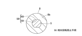
図2および図3に示すように、回転子8と回転入出力軸5とが円周方向に相対回転することを阻止する相対回転阻止手段58が設けられている。この相対回転阻止手段58は、例えば、回転子8の内周面の180度対向位置に互いに平行に形成された平面接触部59と、回転入出力軸5の外周面に形成され平面接触部59に結合される平面被接触部60とを有する。これら平面接触部59,平面被接触部60は、例えば、二面幅カット加工により形成される二面幅である。
3 is a cross-sectional view taken along line III-III in FIG.
As shown in FIGS. 2 and 3, there is provided relative rotation preventing means 58 for preventing the
相対回転阻止手段58は、二面幅だけに限定されるものではなく、例えば、Dカット加工により形成される平面接触部および平面被接触部としても良い。その他、相対回転阻止手段58は、回転子8と回転入出力軸5とが互いに結合される面に、スプライン加工またはセレーション加工により形成される嵌合面、ねじ加工により形成される螺子加工面等を設けても良い。
The relative rotation preventing means 58 is not limited to the two-sided width, and may be, for example, a flat contact portion and a flat contacted portion formed by D-cut processing. In addition, the relative rotation preventing means 58 includes a fitting surface formed by spline processing or serration processing on a surface where the
直動機構3について説明する。
図1に示すように、ハウジング4内における直動機構収容部4aに、直動機構3の大部分が組み込まれている。直動機構3は、電動モータ2の出力により、後述するブレーキロータに対して制動力を負荷する。この直動機構3は、電動モータ2の回転運動を回転入出力軸5を介して直動部6の直進運動に変換する。
The linear motion mechanism 3 will be described.
As shown in FIG. 1, most of the linear motion mechanism 3 is incorporated in the linear motion
直動機構3は、電動モータ2により回転駆動される回転入出力軸5と、この回転入出力軸5の回転運動を直進運動に変換する変換機構部31とを有する。変換機構部31は、直動部6と、軸受ケース32と、環状のスラスト板であるバックプレート33と、直動部6の直進運動に伴う軸方向の荷重に対する反作用力を保持するスラスト軸受34と、ラジアル軸受35と、キャリア36と、すべり軸受37,38と、遊星ローラ39とを有する。
直動機構収容部4aの内周面に、円筒状の直動部6が、回り止めされ且つ軸方向に移動自在に支持されている。直動部6の内周面には、径方向内方に突出し螺旋状に形成された螺旋突起が設けられている。この螺旋突起に複数の遊星ローラ39が噛合している。
The linear motion mechanism 3 includes a rotational input /
A cylindrical
直動機構収容部4aにおける直動部6の軸方向一端側に、軸受ケース32が設けられている。この軸受ケース32は、円筒状のボス部32aと、このボス部32aから径方向外方に延びるフランジ部32bと、このフランジ部32bの外径側端に繋がる外筒部32cとを有する。これら外筒部32c、フランジ部32b、およびボス部32aは一体に形成されている。直動機構収容部4aの内周面に、外筒部32cの外周面が例えば焼嵌めまたは溶接等を用いて固定されている。これと共に、隔壁4cにフランジ部32bの軸方向一端面が当接されている。
A bearing
なおハウジング4に対する軸受ケース32の固定方法は、前記焼嵌めまたは溶接だけに限定されるものではなく、図示しないが、例えば、ハウジング4の直動機構収容部4aの内周面に、環状溝を設け、この環状溝に止め輪等を用いて軸受ケース32をハウジング4に固定しても良い。ハウジング4に軸受ケース32が固定されたうえで、後述するように軸受ケース32にラジアル軸受35が嵌合され、さらにラジアル軸受35に回転入出力軸5が嵌合されている。
The method of fixing the bearing
したがって、ハウジング4に対して、回転部材53が、ラジアル軸受35および軸受ケース32によって前記径方向に保持され拘束される。ラジアル軸受35および軸受ケース32が、ハウジング4に対して回転部材53を径方向に拘束する径方向の拘束部54に相当する。軸方向および径方向について共通の拘束部54である「ラジアル軸受35および軸受ケース32」が、直動部6と電動モータ2との軸方向の中間に設けられる。
Therefore, the rotating member 53 is held and restrained in the radial direction by the
軸受ケース32におけるボス部32a内に複数(この例では二つ)のラジアル軸受35が嵌合され、これらラジアル軸受35の内径面に回転入出力軸5が嵌合されている。回転入出力軸5は、軸受ケース32に複数のラジアル軸受35を介して回転自在に支持される。各ラジアル軸受35は、ラジアル荷重およびアキシアル荷重を保持可能な軸受が適用される。ラジアル軸受35およびスラスト軸受34は、軸受ケース32に対して所定の拘束力を発揮する。
A plurality of (two in this example)
この実施形態では、スラスト軸受34として針状ころ軸受、ラジアル軸受35としてすべり軸受を用いているが、この例に限定されるものではない。スラスト軸受34として、例えば、玉軸受、円筒ころ軸受、テーパころ軸受、すべり軸受等、任意の構造を適宜用いることができる。ラジアル軸受35として、例えば、フランジ付のすべり軸受または玉軸受等の軸受であって、ラジアル荷重およびアキシアル荷重を保持可能な軸受を適宜用いることができる。
In this embodiment, a needle roller bearing is used as the
直動部6の内周には、回転入出力軸5を中心に回転可能なキャリア36が設けられている。キャリア36は、回転入出力軸5との間に嵌合されたすべり軸受37,38により、回転入出力軸5に回転自在に支持されている。軸受ケース32に対して、キャリア36および回転入出力軸5の軸方向位置が、軸方向先端部分の止め輪56により拘束される。
A
キャリア36には、複数のローラ軸41が周方向に間隔を空けて設けられている。キャリア36の軸方向両端部には、それぞれ軸挿入孔が複数形成されている。各軸挿入孔は、径方向に所定距離延びる長孔から成る。各軸挿入孔に各ローラ軸41の軸方向両端部が挿入されて、これらローラ軸41が各軸挿入孔の範囲で径方向に移動自在に支持される。複数のローラ軸41における軸方向両端部には、これらローラ軸41を径方向内方に付勢する弾性リング42がそれぞれ掛け渡されている。
The
各ローラ軸41に、遊星ローラ39が回転自在に支持される。各遊星ローラ39の外周面には、直動部6の螺旋突起に噛合する円周溝または螺旋溝が形成されている。各遊星ローラ39は、回転入出力軸5の外周面と、直動部6の内周面との間に介在される。弾性リング42の付勢力により、各遊星ローラ39が回転入出力軸5の外周面に押し付けられる。電動モータ2により回転入出力軸5が回転することで、この回転入出力軸5の外周面に接触する各遊星ローラ39が接触摩擦により回転する。これにより直動部6が軸方向に移動することで、この直動部6の軸方向先端に設けられた摩擦パッド43(図6)がブレーキロータ44(図6)に対して当接離隔する。
A
以上説明した電動式直動アクチュエータ1によれば、電動モータ2はいわゆるアキシアルギャップモータであり、さらに直動機構3と電動モータ2とが、直動機構3の回転入出力軸5の軸心となる同一の軸心上に並んで配置されている。このため、特許文献2のような、電動モータと直動アクチュエータとを平行に配置する構造等に比べて、無効なスペースが少なく省スペース化を図ることができ、且つ、慣性モーメントが小さく高応答な電動式直動アクチュエータを実現できる。
According to the electric linear motion actuator 1 described above, the
電動モータ2の保持部8bと回転入出力軸5とが同心に連結される複数の部材から成る回転部材53であるため、減速機を削減可能となり特に径方向の省スペース化を図りつつ構造を簡素化することが可能となる。さらにハウジング4に対して回転部材53が、軸方向および径方向について共通の拘束部54である「ラジアル軸受35および軸受ケース32」によって保持されている。換言すれば、「ラジアル軸受35および軸受ケース32」が軸方向および径方向の拘束部54として兼用されている。このため、スラスト力に対する支持構造を簡素化し部品点数の低減を図ることができる。これにより省スペース化およびコスト低減を図ることができる。
Since the holding
ラジアル軸受35および軸受ケース32が、直動部6と電動モータ2との軸方向の中間に設けられるため、例えば、同一のハウジング内に電動モータおよびアクチュエータを平行に配置する従来構造などと比べて、組立性の向上および直動機構3などの汎用性の向上を図ることができる。
Since the
前記相対回転阻止手段58を備えたため、回転子8から回転入出力軸5へのトルク伝達を可能とし得る。また、回転子8と回転入出力軸5とを一体に回転させることができ、例えば、モータとアクチュエータとの間に減速機を介在させた従来構造よりも、構造を簡素化することができ、省スペース化を図ることができる。
Since the relative rotation blocking means 58 is provided, it is possible to transmit torque from the
回転子8は、図1に示すように、軸方向に貫通する永久磁石8aを用いると、省スペースな実装が可能となるが、例えば、中間に磁性体から成るバックヨーク(図示せず)を配置し、そのバックヨークの軸方向両面に磁石(図示せず)を貼り合わせる構造とすることもできる。この場合、耐熱性を向上させることができる。
As shown in FIG. 1, the
他の実施形態について説明する。
以下の説明においては、各実施の形態で先行して説明している事項に対応している部分には同一の参照符号を付し、重複する説明を略する。構成の一部のみを説明している場合、構成の他の部分は、特に記載のない限り先行して説明している形態と同様とする。同一の構成から同一の作用効果を奏する。実施の各形態で具体的に説明している部分の組合せばかりではなく、特に組合せに支障が生じなければ、実施の形態同士を部分的に組合せることも可能である。
Another embodiment will be described.
In the following description, the same reference numerals are given to portions corresponding to the matters described in advance in the respective embodiments, and overlapping descriptions are omitted. When only a part of the configuration is described, the other parts of the configuration are the same as those described in advance unless otherwise specified. The same effect is obtained from the same configuration. Not only the combination of the parts specifically described in each embodiment, but also the embodiments can be partially combined as long as the combination does not hinder.
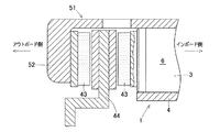
図4に示す電動式直動アクチュエータ1では、電動モータ2として、中間に軸方向両面に磁極を持つ固定子7を配置し、この固定子7の両側に回転子8,8を配置するダブルロータ構造のアキシアルギャップモータを用いる例を示す。この電動モータ2は、回転軸方向両面に貫通してトルクに寄与する鎖交磁束を発生するコイル11を配設した固定子7と、この固定子7の軸方向両側に片面に鎖交磁束発生面を有する回転子8,8とを備える。
In the electric linear actuator 1 shown in FIG. 4, as the
各回転子8は、永久磁石8a、この永久磁石8aを保持する保持部8b、およびバックヨーク8cを備えている。回転入出力軸5の先端部分の外周面に、先端側から順次、止め輪56、カラー15、モータ間座57が設けられている。止め輪56とカラー15との間に、一方の回転子8が軸方向に位置決めされ固定されている。カラー15とモータ間座57との間に、他方の回転子8が軸方向に位置決めされ固定されている。止め輪56、カラー15、およびモータ間座57により、固定子7と各回転子8とのギャップ(隙間)が定められる。固定子7は例えばモータ収容部4b内側に配置され、モータ収容部4bに当接するように配置されている。その他前述の実施形態と同様の構成となっている。
Each
以上説明したダブルロータ構造のアキシアルギャップモータを備えた電動式直動アクチュエータ1においても、省スペース化を図ると共に、スラスト力に対する支持構造を簡素化しコスト低減を図ることができる。前記バックヨーク8cを磁性体を用いて形成すると、耐熱性が向上し好適と考えられる。その他前述の実施形態と同様の作用効果を奏する。
固定子7は、本図4のように軸方向に貫通する形状とする他、中間に磁性体から成るバックヨーク(図示せず)を配置し、そのバックヨークの両面に図示外のコイルを貼り合わせる形状とすることもできる。本構造を用いると、比較的省電力で高トルクを実現できる。
In the electric linear actuator 1 including the double rotor structure axial gap motor described above, it is possible to save space, simplify the support structure for the thrust force, and reduce the cost. If the
The
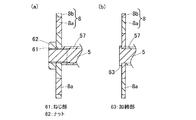
回転子8の回転軸方向の拘束に、図2の環状溝55および止め輪56に代えて、図5(a)に示すように、ねじ部61およびナット62を適用しても良い。回転入出力軸5の外周面にねじ部61が形成され、このねじ部61にナット62が螺合されている。このナット62の座面とモータ間座57との間に回転子8が軸方向に位置決めされて固定されている。この構成において、回転子8の内周面と回転入出力軸5の外周面とが、ねじ係合されていても良く、ねじ結合ではない嵌め合いでも良い。回転子8の内周面と回転入出力軸5の外周面とがねじ係合されている場合、ナット62を用いない構造としても良い。
Instead of the
回転子8の回転軸方向の拘束に、図2の環状溝55および止め輪56に代えて、図5(b)に示すように、加締部63を適用しても良い。回転入出力軸5の軸方向端部に、加締部63が形成されている。回転入出力軸5の軸方向端部が加締め加工されることで、加締部63が形成される。この場合、図2、図5(a)の構成よりも、スラスト力に対する支持構造を簡素化し部品点数の低減を図れる。
In place of the
図示しないが、固定子と回転子それぞれが片面のみ鎖交磁束発生面を有するシングル型アキシアルギャップモータを構成することもできる。この構成は、要求されるモータトルクが比較的小さいような場合、より省スペースなアクチュエータを構成するうえで好適となる。 Although not shown, a single-type axial gap motor in which each of the stator and the rotor has an interlinkage magnetic flux generating surface on one side can also be configured. This configuration is suitable for constructing a more space-saving actuator when the required motor torque is relatively small.
図6は、いずれかの電動式直動アクチュエータ1を備えた電動ブレーキ装置の一部破断した断面図である。この電動ブレーキ装置は、いずれかの電動式直動アクチュエータ1と、車輪と一体に回転する回転部材であるブレーキロータ44と、このブレーキロータ44と接触して制動力を発生する摩擦パッド(摩擦材)43と、電動式直動アクチュエータ1を制御する図示外の制御装置とを備える。車両には、ブレーキロータ44の外周側部分を囲むようにキャリパ51がそれぞれ設けられる。キャリパ51は、電動式直動アクチュエータ1のハウジング4に一体に設けられている。
FIG. 6 is a partially broken cross-sectional view of an electric brake device including any one of the electric linear actuators 1. This electric brake device includes any one of the electric linear actuator 1, a
キャリパ51のアウトボード側の端部に、爪部52が設けられる。爪部52は、ブレーキロータ44のアウトボード側の側面と軸方向で対向する。この爪部52にアウトボード側の摩擦パッド43が支持されている。
キャリパ51のうち、直動機構3の直動部6のアウトボード側端に、インボード側の摩擦パッド43が支持されている。この摩擦パッド43は、ブレーキロータ44のインボード側の側面と軸方向で対向する。電動式直動アクチュエータ1は、摩擦パッド43をブレーキロータ44に対して当接離隔させる駆動を行う。
A
In the
車両における図示外のナックルに、マウント(図示せず)が支持される。このマウントの長手方向両端部には、一対のピン支持片(図示せず)が設けられる。これらピン支持片のそれぞれ端部に、軸方向に平行に延びる図示外のスライドピンが設けられる。これらスライドピンに、キャリパ51が軸方向にスライド自在に支持されている。
A mount (not shown) is supported by a knuckle (not shown) in the vehicle. A pair of pin support pieces (not shown) are provided at both longitudinal ends of the mount. A slide pin (not shown) extending parallel to the axial direction is provided at each end portion of the pin support pieces. A
前記制御装置は、図示外のブレーキペダルの操作量に応じて、電動式直動アクチュエータ1の電動モータを制御する。制動時、電動式直動アクチュエータ1の駆動によりインボード側の摩擦パッド43がブレーキロータ44に当接して、ブレーキロータ44を軸方向に押圧する。その押圧力の反力によりキャリパ51がインボード側にスライドする。これにより、キャリパ51の爪部52に支持されたアウトボード側の摩擦パッド43がブレーキロータ44に当接する。これらアウトボード側およびインボード側の摩擦パッド43,43で、ブレーキロータ44を軸方向両側から強く挟持することで、ブレーキロータ44に制動力が負荷される。
The control device controls the electric motor of the electric linear actuator 1 according to the operation amount of a brake pedal (not shown). During braking, the
この構成によると、電動式直動アクチュエータ1が省スペース化を図れるため、電動式直動アクチュエータ1の搭載スペースが極めて限られた車両にも、この電動ブレーキ装置を搭載することが可能となる。したがって、電動ブレーキ装置の汎用性を高めることができ、種々な車両にこの電動ブレーキ装置を搭載することができる。また電動式直動アクチュエータ1はスラスト力に対する支持構造を簡素化しコスト低減を図ることができるため、電動ブレーキ装置全体のコスト低減を図れる。 According to this configuration, since the electric linear actuator 1 can save space, the electric brake device can be mounted on a vehicle in which the mounting space for the electric linear actuator 1 is extremely limited. Therefore, the versatility of the electric brake device can be enhanced, and the electric brake device can be mounted on various vehicles. In addition, since the electric linear actuator 1 can simplify the support structure against the thrust force and reduce the cost, the cost of the entire electric brake device can be reduced.
電動モータ2の保持部8bと回転入出力軸5とが同一の部材から成る回転部材であっても良い。
回転子は、非磁性材料から成る保持部で永久磁石を保持すると、損失が少なく好適と考えられるが、磁性材から成る保持部で永久磁石を保持することもできる。回転子は、保持部を用いずに、複数の軸方向磁極に着磁された単一の磁石を、直接、回転入出力軸に固定する構造とすることもできる。
The holding
It is considered that the rotor is preferable when the permanent magnet is held by a holding portion made of a non-magnetic material, with less loss, but the permanent magnet can also be held by a holding portion made of a magnetic material. The rotor may have a structure in which a single magnet magnetized on a plurality of axial magnetic poles is directly fixed to the rotation input / output shaft without using a holding portion.
前記モータ間座を用いる代わりに、回転入出力軸を軸方向位置に応じて外径寸法が異なる段付形状とすることもできる。
電動モータは、例えば、固定子に永久磁石、回転子にコイルおよびブラシ等を用いたDCモータの構成を採ることもでき、あるいは、回転子が回転することによって固定子インダクタンスが変化する形状の鉄心を用いたリラクタンスモータの構成を採ることもできる。
Instead of using the motor spacer, the rotary input / output shaft may be formed in a stepped shape having different outer diameters depending on the axial position.
For example, the electric motor may be configured as a DC motor using a permanent magnet as a stator and a coil and a brush as a rotor, or an iron core having a shape in which the stator inductance changes as the rotor rotates. The structure of the reluctance motor using can also be taken.
直動機構の変換機構部として、遊星ローラ以外にボールねじ等の各種ねじ機構、ボールランプ等の傾斜を利用した機構等を用いることができる。
モータ角度を検出するセンサやサーミスタ、各電装系の配線部品など、電動式直動アクチュエータの適用に必要な構成は適宜設けられるものとする。
各実施形態の電動式直動アクチュエータを、電動ブレーキ装置以外の、例えば、プレス装置に適用することも可能である。
As the conversion mechanism portion of the linear motion mechanism, various screw mechanisms such as a ball screw, a mechanism using an inclination of a ball ramp, etc. can be used in addition to the planetary roller.
The components necessary for the application of the electric linear actuator, such as a sensor and thermistor for detecting the motor angle, and wiring components for each electrical system, are appropriately provided.
It is also possible to apply the electric linear actuator of each embodiment to, for example, a press device other than the electric brake device.
以上、実施形態に基づいてこの発明を実施するための形態を説明したが、今回開示された実施の形態はすべての点で例示であって制限的なものではない。この発明の範囲は上記した説明ではなくて特許請求の範囲によって示され、特許請求の範囲と均等の意味および範囲内でのすべての変更が含まれることが意図される。 As mentioned above, although the form for implementing this invention based on embodiment was demonstrated, embodiment disclosed this time is an illustration and restrictive at no points. The scope of the present invention is defined by the terms of the claims, rather than the description above, and is intended to include any modifications within the scope and meaning equivalent to the terms of the claims.
1…電動式直動アクチュエータ
2…電動モータ
3…直動機構
4…ハウジング
5…回転入出力軸
6…直動部
7…固定子
8…回転子
53…回転部材
54…拘束部
55…環状溝
56…止め輪
58…相対回転阻止手段
61…ねじ部
62…ナット
63…加締部
DESCRIPTION OF SYMBOLS 1 ... Electric
Claims (5)
前記直動機構と前記電動モータとが、前記直動機構の前記回転入出力軸の軸心となる同一の軸心上に並んで配置され、
前記電動モータは、トルクに寄与する鎖交磁束を発生する磁極の向きが、前記電動モータにおける回転軸と平行となるように配置された固定子および回転子を備え、
前記電動モータの前記回転軸と前記回転入出力軸とが同一の部材または同心に連結される複数の部材から成る回転部材であり、前記ハウジングに対して前記回転部材が、前記回転軸における、軸方向および径方向について共通の拘束部によって保持された電動式直動アクチュエータ。 In an electric linear motion actuator comprising: an electric motor; a linear motion mechanism that converts rotational motion of the electric motor into linear motion of a linear motion portion via a rotational input / output shaft; and a housing that holds the linear motion mechanism ,
The linear motion mechanism and the electric motor are arranged side by side on the same axis serving as the axis of the rotation input / output shaft of the linear motion mechanism,
The electric motor includes a stator and a rotor arranged such that the direction of the magnetic poles that generate the interlinkage magnetic flux contributing to the torque is parallel to the rotation axis of the electric motor,
The rotary shaft of the electric motor and the rotary input / output shaft are the same member or a rotary member composed of a plurality of members connected concentrically, and the rotary member is a shaft of the rotary shaft relative to the housing. An electric linear actuator that is held by a common restricting portion in the direction and the radial direction.
前記回転入出力軸の外周面に形成された環状溝とこの環状溝に嵌り込む止め輪、前記回転入出力軸の外周面に形成されたねじ部とこのねじ部に螺合されたナット、または、前記回転入出力軸の軸方向端部に形成された加締部を含む電動式直動アクチュエータ。 The electric linear actuator according to claim 3, wherein the restraining portion is
An annular groove formed on the outer peripheral surface of the rotary input / output shaft and a retaining ring fitted into the annular groove, a screw portion formed on the outer peripheral surface of the rotary input / output shaft, and a nut screwed into the screw portion, or An electric linear actuator including a crimping portion formed at an axial end portion of the rotation input / output shaft.
Priority Applications (5)
| Application Number | Priority Date | Filing Date | Title |
|---|---|---|---|
| JP2016123138A JP6779673B2 (en) | 2016-06-22 | 2016-06-22 | Electric linear actuator |
| CN201780038024.8A CN109417331B (en) | 2016-06-22 | 2017-06-16 | Electric linear motion actuator |
| PCT/JP2017/022385 WO2017221843A1 (en) | 2016-06-22 | 2017-06-16 | Electric linear actuator |
| EP17815311.0A EP3477825A4 (en) | 2016-06-22 | 2017-06-16 | Electric linear actuator |
| US16/225,430 US20190123616A1 (en) | 2016-06-22 | 2018-12-19 | Electric linear actuator |
Applications Claiming Priority (1)
| Application Number | Priority Date | Filing Date | Title |
|---|---|---|---|
| JP2016123138A JP6779673B2 (en) | 2016-06-22 | 2016-06-22 | Electric linear actuator |
Publications (2)
| Publication Number | Publication Date |
|---|---|
| JP2017229148A true JP2017229148A (en) | 2017-12-28 |
| JP6779673B2 JP6779673B2 (en) | 2020-11-04 |
Family
ID=60784107
Family Applications (1)
| Application Number | Title | Priority Date | Filing Date |
|---|---|---|---|
| JP2016123138A Expired - Fee Related JP6779673B2 (en) | 2016-06-22 | 2016-06-22 | Electric linear actuator |
Country Status (5)
| Country | Link |
|---|---|
| US (1) | US20190123616A1 (en) |
| EP (1) | EP3477825A4 (en) |
| JP (1) | JP6779673B2 (en) |
| CN (1) | CN109417331B (en) |
| WO (1) | WO2017221843A1 (en) |
Cited By (2)
| Publication number | Priority date | Publication date | Assignee | Title |
|---|---|---|---|---|
| CN108736675A (en) * | 2018-07-05 | 2018-11-02 | 中国科学院宁波材料技术与工程研究所 | A kind of moving-coil type unipolarity permanent magnet rotational alignment motor |
| WO2019141738A1 (en) * | 2018-01-22 | 2019-07-25 | Logicdata Electronic & Software Entwicklungs Gmbh | Linear actuator for a furniture system, electrically adjustable furniture system, method for installing a linear actuator in a furniture system, and furniture system arrangement |
Family Cites Families (14)
| Publication number | Priority date | Publication date | Assignee | Title |
|---|---|---|---|---|
| JPS52131110A (en) * | 1976-04-27 | 1977-11-02 | Matsushita Electric Works Ltd | Rotor of synchronous motor |
| JPS5822844U (en) * | 1981-08-03 | 1983-02-12 | 株式会社東海理化電機製作所 | Linear output motor |
| US6098479A (en) * | 1997-08-23 | 2000-08-08 | Hoermansdoerfer; Gerd | Linear actuator and preferred application |
| JP3716653B2 (en) * | 1999-01-27 | 2005-11-16 | 日本精工株式会社 | Linear motor |
| US6392322B1 (en) * | 2000-01-31 | 2002-05-21 | Precision Engine Controls Corporation | Rugged explosion-proof actuator with integral electronics |
| JP3750933B2 (en) | 2002-02-22 | 2006-03-01 | 日信工業株式会社 | Electric disc brake layout |
| JP4898123B2 (en) * | 2005-01-13 | 2012-03-14 | Ntn株式会社 | Electric linear actuator and electric brake device |
| JP5111863B2 (en) | 2007-01-10 | 2013-01-09 | 本田技研工業株式会社 | Axial gap type motor and electric power steering device |
| TWI455458B (en) * | 2007-09-20 | 2014-10-01 | Thk Co Ltd | Linear actuator |
| FR2935029B1 (en) * | 2008-08-12 | 2012-05-04 | Valeo Equip Electr Moteur | STARTER COMPRISING AN ARMOR ARMOR CARRIED BY A BEARING INTERPOSE BETWEEN INDUCTOR AND REDUCTOR |
| JP2010270788A (en) | 2009-05-19 | 2010-12-02 | Akebono Brake Ind Co Ltd | Disc brake |
| JP5069368B2 (en) * | 2011-09-28 | 2012-11-07 | Ntn株式会社 | Electric brake device |
| JP6076059B2 (en) * | 2012-12-03 | 2017-02-08 | Ntn株式会社 | Electric brake device for vehicle |
| JP6710578B2 (en) * | 2016-05-19 | 2020-06-17 | Ntn株式会社 | Electric linear actuator |
-
2016
- 2016-06-22 JP JP2016123138A patent/JP6779673B2/en not_active Expired - Fee Related
-
2017
- 2017-06-16 EP EP17815311.0A patent/EP3477825A4/en not_active Withdrawn
- 2017-06-16 CN CN201780038024.8A patent/CN109417331B/en active Active
- 2017-06-16 WO PCT/JP2017/022385 patent/WO2017221843A1/en unknown
-
2018
- 2018-12-19 US US16/225,430 patent/US20190123616A1/en not_active Abandoned
Cited By (3)
| Publication number | Priority date | Publication date | Assignee | Title |
|---|---|---|---|---|
| WO2019141738A1 (en) * | 2018-01-22 | 2019-07-25 | Logicdata Electronic & Software Entwicklungs Gmbh | Linear actuator for a furniture system, electrically adjustable furniture system, method for installing a linear actuator in a furniture system, and furniture system arrangement |
| CN108736675A (en) * | 2018-07-05 | 2018-11-02 | 中国科学院宁波材料技术与工程研究所 | A kind of moving-coil type unipolarity permanent magnet rotational alignment motor |
| CN108736675B (en) * | 2018-07-05 | 2023-11-14 | 中国科学院宁波材料技术与工程研究所 | Moving-coil type unipolar permanent magnet rotary linear motor |
Also Published As
| Publication number | Publication date |
|---|---|
| US20190123616A1 (en) | 2019-04-25 |
| CN109417331A (en) | 2019-03-01 |
| WO2017221843A1 (en) | 2017-12-28 |
| CN109417331B (en) | 2021-07-09 |
| EP3477825A1 (en) | 2019-05-01 |
| JP6779673B2 (en) | 2020-11-04 |
| EP3477825A4 (en) | 2020-02-05 |
Similar Documents
| Publication | Publication Date | Title |
|---|---|---|
| WO2018008709A1 (en) | Electric linear actuator | |
| JP6710578B2 (en) | Electric linear actuator | |
| US5982063A (en) | Electric motor with internal brake | |
| JP5205594B2 (en) | Rotating electric machine | |
| WO2018038020A1 (en) | Electric linear motion actuator | |
| US11060576B2 (en) | Electric linear motion actuator | |
| JP2008011599A (en) | Brushless motor | |
| WO2018034247A1 (en) | Electric motor device | |
| WO2017221843A1 (en) | Electric linear actuator | |
| WO2019124543A1 (en) | Coreless motor | |
| WO2019123666A1 (en) | Coreless motor | |
| WO2006118533A1 (en) | Releasable rotor | |
| JP2008017588A (en) | Driving mechanism | |
| JP2010017010A (en) | Axial gap motor | |
| WO2013076788A1 (en) | Brake device and rotating electric machine | |
| JP2004205026A (en) | Rolling bearing device built in motor | |
| JP2014057456A (en) | Rotor for electric motor | |
| JP2023127999A (en) | Motor and electric bike having the same | |
| JP2022079015A (en) | Gear motor | |
| JP2004132468A (en) | Electromagnetic clutch and brake device | |
| JP2006304458A (en) | Eddy current reduction gear |
Legal Events
| Date | Code | Title | Description |
|---|---|---|---|
| A621 | Written request for application examination |
Free format text: JAPANESE INTERMEDIATE CODE: A621 Effective date: 20190528 |
|
| A131 | Notification of reasons for refusal |
Free format text: JAPANESE INTERMEDIATE CODE: A131 Effective date: 20200317 |
|
| A521 | Request for written amendment filed |
Free format text: JAPANESE INTERMEDIATE CODE: A523 Effective date: 20200420 |
|
| TRDD | Decision of grant or rejection written | ||
| A01 | Written decision to grant a patent or to grant a registration (utility model) |
Free format text: JAPANESE INTERMEDIATE CODE: A01 Effective date: 20200929 |
|
| A61 | First payment of annual fees (during grant procedure) |
Free format text: JAPANESE INTERMEDIATE CODE: A61 Effective date: 20201014 |
|
| R150 | Certificate of patent or registration of utility model |
Ref document number: 6779673 Country of ref document: JP Free format text: JAPANESE INTERMEDIATE CODE: R150 |
|
| LAPS | Cancellation because of no payment of annual fees |