WO2018008709A1 - Electric linear actuator - Google Patents
Electric linear actuator Download PDFInfo
- Publication number
- WO2018008709A1 WO2018008709A1 PCT/JP2017/024737 JP2017024737W WO2018008709A1 WO 2018008709 A1 WO2018008709 A1 WO 2018008709A1 JP 2017024737 W JP2017024737 W JP 2017024737W WO 2018008709 A1 WO2018008709 A1 WO 2018008709A1
- Authority
- WO
- WIPO (PCT)
- Prior art keywords
- winding
- electric
- linear actuator
- electric motor
- coil
- Prior art date
Links
Images


Classifications
-
- H—ELECTRICITY
- H02—GENERATION; CONVERSION OR DISTRIBUTION OF ELECTRIC POWER
- H02K—DYNAMO-ELECTRIC MACHINES
- H02K3/00—Details of windings
- H02K3/04—Windings characterised by the conductor shape, form or construction, e.g. with bar conductors
- H02K3/18—Windings for salient poles
-
- H—ELECTRICITY
- H02—GENERATION; CONVERSION OR DISTRIBUTION OF ELECTRIC POWER
- H02K—DYNAMO-ELECTRIC MACHINES
- H02K3/00—Details of windings
- H02K3/04—Windings characterised by the conductor shape, form or construction, e.g. with bar conductors
- H02K3/28—Layout of windings or of connections between windings
-
- B—PERFORMING OPERATIONS; TRANSPORTING
- B60—VEHICLES IN GENERAL
- B60T—VEHICLE BRAKE CONTROL SYSTEMS OR PARTS THEREOF; BRAKE CONTROL SYSTEMS OR PARTS THEREOF, IN GENERAL; ARRANGEMENT OF BRAKING ELEMENTS ON VEHICLES IN GENERAL; PORTABLE DEVICES FOR PREVENTING UNWANTED MOVEMENT OF VEHICLES; VEHICLE MODIFICATIONS TO FACILITATE COOLING OF BRAKES
- B60T13/00—Transmitting braking action from initiating means to ultimate brake actuator with power assistance or drive; Brake systems incorporating such transmitting means, e.g. air-pressure brake systems
- B60T13/74—Transmitting braking action from initiating means to ultimate brake actuator with power assistance or drive; Brake systems incorporating such transmitting means, e.g. air-pressure brake systems with electrical assistance or drive
-
- H—ELECTRICITY
- H02—GENERATION; CONVERSION OR DISTRIBUTION OF ELECTRIC POWER
- H02K—DYNAMO-ELECTRIC MACHINES
- H02K1/00—Details of the magnetic circuit
- H02K1/06—Details of the magnetic circuit characterised by the shape, form or construction
- H02K1/22—Rotating parts of the magnetic circuit
- H02K1/27—Rotor cores with permanent magnets
- H02K1/2793—Rotors axially facing stators
- H02K1/2795—Rotors axially facing stators the rotor consisting of two or more circumferentially positioned magnets
- H02K1/2796—Rotors axially facing stators the rotor consisting of two or more circumferentially positioned magnets where both axial sides of the rotor face a stator
-
- H—ELECTRICITY
- H02—GENERATION; CONVERSION OR DISTRIBUTION OF ELECTRIC POWER
- H02K—DYNAMO-ELECTRIC MACHINES
- H02K21/00—Synchronous motors having permanent magnets; Synchronous generators having permanent magnets
- H02K21/12—Synchronous motors having permanent magnets; Synchronous generators having permanent magnets with stationary armatures and rotating magnets
- H02K21/24—Synchronous motors having permanent magnets; Synchronous generators having permanent magnets with stationary armatures and rotating magnets with magnets axially facing the armatures, e.g. hub-type cycle dynamos
-
- H—ELECTRICITY
- H02—GENERATION; CONVERSION OR DISTRIBUTION OF ELECTRIC POWER
- H02K—DYNAMO-ELECTRIC MACHINES
- H02K3/00—Details of windings
- H02K3/04—Windings characterised by the conductor shape, form or construction, e.g. with bar conductors
-
- H—ELECTRICITY
- H02—GENERATION; CONVERSION OR DISTRIBUTION OF ELECTRIC POWER
- H02K—DYNAMO-ELECTRIC MACHINES
- H02K3/00—Details of windings
- H02K3/46—Fastening of windings on the stator or rotor structure
- H02K3/52—Fastening salient pole windings or connections thereto
- H02K3/521—Fastening salient pole windings or connections thereto applicable to stators only
- H02K3/522—Fastening salient pole windings or connections thereto applicable to stators only for generally annular cores with salient poles
-
- H—ELECTRICITY
- H02—GENERATION; CONVERSION OR DISTRIBUTION OF ELECTRIC POWER
- H02K—DYNAMO-ELECTRIC MACHINES
- H02K7/00—Arrangements for handling mechanical energy structurally associated with dynamo-electric machines, e.g. structural association with mechanical driving motors or auxiliary dynamo-electric machines
- H02K7/06—Means for converting reciprocating motion into rotary motion or vice versa
-
- H—ELECTRICITY
- H02—GENERATION; CONVERSION OR DISTRIBUTION OF ELECTRIC POWER
- H02K—DYNAMO-ELECTRIC MACHINES
- H02K7/00—Arrangements for handling mechanical energy structurally associated with dynamo-electric machines, e.g. structural association with mechanical driving motors or auxiliary dynamo-electric machines
- H02K7/10—Structural association with clutches, brakes, gears, pulleys or mechanical starters
- H02K7/116—Structural association with clutches, brakes, gears, pulleys or mechanical starters with gears
-
- F—MECHANICAL ENGINEERING; LIGHTING; HEATING; WEAPONS; BLASTING
- F16—ENGINEERING ELEMENTS AND UNITS; GENERAL MEASURES FOR PRODUCING AND MAINTAINING EFFECTIVE FUNCTIONING OF MACHINES OR INSTALLATIONS; THERMAL INSULATION IN GENERAL
- F16D—COUPLINGS FOR TRANSMITTING ROTATION; CLUTCHES; BRAKES
- F16D65/00—Parts or details
- F16D65/14—Actuating mechanisms for brakes; Means for initiating operation at a predetermined position
- F16D65/16—Actuating mechanisms for brakes; Means for initiating operation at a predetermined position arranged in or on the brake
Definitions
- the present invention relates to, for example, an electric linear actuator applied to an electric brake device.
- Electric actuators and electric motors have been proposed in the following documents.
- An electric disc brake device in which an electric motor is arranged coaxially with the linear motion part on the outer periphery of the linear motion part (Patent Document 1).
- An electric brake device in which an electric motor is arranged on an axis parallel to the rotation axis of the linear motion mechanism and different from the rotation axis (Patent Document 2).
- An electric brake device in which an electric motor is arranged on an axis parallel to the rotation axis of the linear motion mechanism and different from the rotation axis (Patent Document 2).
- a 8-pole, 9-slot double stator type axial gap motor Patent Document 3).
- an electric brake device using an electric linear actuator as described in Patent Documents 1 and 2 has a very limited space for mounting on a vehicle, and it is necessary to realize a function with as little space as possible.
- an electric brake is required to have high-speed and high-precision brake force control.
- Patent Document 3 As an example of a motor structure that realizes high torque in a small space, an axial gap type synchronous motor as shown in Patent Document 3, for example, is known. However, since an axial gap motor generally has a large radial dimension, using the structure of Patent Document 1 or Patent Document 2 may increase the mounting space.
- An object of the present invention is to provide an electric linear actuator that can reduce the mounting space and cost.
- the electric linear actuator of the present invention includes an electric motor, a linear motion mechanism that has a rotational input / output shaft and converts the rotational motion of the electric motor to the linear motion of the linear motion portion via the rotational input / output shaft,
- An electric linear actuator comprising a housing that holds the linear motion mechanism and a control device that controls the electric motor,
- the linear motion mechanism and the electric motor are arranged side by side on the same axis serving as the axis of the rotation input / output shaft of the linear motion mechanism
- the electric motor includes a stator and a rotor arranged such that the direction of the magnetic poles that generate the interlinkage magnetic flux contributing to the torque is parallel to the rotation axis of the electric motor
- the stator includes an excitation mechanism including a coil that converts a current to be supplied to the electric motor into the linkage flux.
- a wiring mechanism for electrically connecting the coil and the control device One or both of the ends of the winding of the coil have an extended portion that extends in the radial direction of
- the electric motor is a so-called axial gap motor including a stator and a rotor arranged so that the direction of the magnetic poles that generate the interlinkage magnetic flux contributing to the torque is parallel to the rotation axis of the electric motor. is there.
- the linear motion mechanism and the electric motor are arranged side by side on the same axis that is the axis of the rotation input / output shaft of the linear motion mechanism. Therefore, compared to a structure in which the electric motor and the direct acting actuator are arranged in parallel, an electric linear acting actuator that has a small amount of invalid space and can save space, and has a small moment of inertia and high response. realizable.
- the stator is equipped with an excitation mechanism, which includes a coil.
- an excitation mechanism which includes a coil.
- the coil converts the current into the linkage flux.
- the wiring mechanism electrically connects the coil and the control device.
- Either or both ends of the coil windings (coil terminals) have an extended portion extending in the radial direction of the rotating shaft, and the extended portion is connected to the wiring mechanism. .
- the coil terminal has an extended portion extending in the radial direction on the rotating shaft, which facilitates the connection between the coil of the electric motor and the control device, which is advantageous for cost reduction and space saving. . Therefore, it is possible to reduce the mounting space and cost.
- the winding forming the coil has a rectangular cross section viewed by cutting along a plane including the axis of the winding, and the longitudinal direction of the rectangular winding is orthogonal to the rotation axis. And the short winding direction in the cross section of the rectangular winding is arranged to be parallel to the rotation axis, and the winding is wound so as to be laminated in the short direction. Good.
- an extended portion of one end is extended to the radially outer diameter side of the rotating shaft, and an extended portion of the other end is extended to the radially inner diameter side of the rotating shaft. It may be what has been done.
- the winding has a rectangular cross section viewed by cutting along a plane including the axis of the winding.
- a winding having a rectangular cross section for example, a flat wire can be applied.
- the electric motor can be made compact in the axial direction of the rotating shaft, and space saving can be further achieved.
- a stator having high heat dissipation and excellent “space factor” which is a ratio of conductors in the cross section of the winding can be configured.
- the extension of one of the ends is extended to the radially outer diameter side of the rotating shaft, and the extension of the other end is extended to the radially inner diameter side of the rotating shaft.
- the wiring length can be reduced. Thereby, it becomes suitable in reduction of loss and reduction of material cost.
- the winding forming the coil has a rectangular cross section viewed by cutting along a plane parallel to the axial center of the winding, and the longitudinal direction of the cross section of the rectangular winding is the rotation axis. Parallel and arranged so that the short direction in the cross section of the rectangular winding is orthogonal to the rotation axis, and the winding is wound so as to be stacked in the short direction It may be a thing.
- a rectangular wire can be applied.
- the stator can be compactly accommodated in a housing or the like, for example, depending on the number of turns.
- an extended portion of one end is extended to the radially outer diameter side of the rotating shaft, and an extended portion of the other end is parallel to the axial direction of the rotating shaft. It may be extended. In this configuration, when the extended portion of the other end is connected to a so-called neutral point, the wiring length can be reduced. This makes it possible to reduce loss and material cost.
- the excitation mechanism has a coil group corresponding to each phase of a three-phase alternating current,
- the wiring mechanism is The coil is star-connected to have at least one neutral point; Of the both ends of the winding, the extension of the other end is connected to the neutral point, The extension part of said one edge part may be connected with the said control apparatus which controls the said three-phase alternating current among the both ends of the said coil
- the extension portion of the other end portion extending in parallel to the radial inner diameter side or the axial direction is connected to the neutral point, for example, constituting a delta connection
- the wiring length can be surely reduced, and loss and material costs can be reduced. Since the extended part of one end that is extended to the radially outer diameter side is connected to the control device that controls the three-phase alternating current, the electrical connection between the coil and the control device can be made with a connector, etc. Can be done easily.
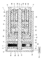
- FIG. 1 is a cross-sectional view of an electric linear actuator according to an embodiment of the present invention.
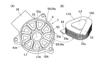
- FIG. 2A is a perspective view showing a schematic shape of the entire stator of an electric motor in the electric linear actuator
- FIG. 2B is an enlarged perspective view showing a shape of a single coil of the stator. It is a figure which shows the example of the wiring mechanism which electrically connects the same coil and a control apparatus.
- A The perspective view which shows schematic shape of the whole stator of the electric motor in the electric linear actuator which concerns on other embodiment of this invention
- FIG. It is sectional drawing of the electrically driven linear motion actuator which concerns on further another embodiment of this invention. It is sectional drawing which fractured
- the electric linear actuator 1 is an actuator in which an electric motor 2 and a linear mechanism 3 are connected in series in the axial direction.
- the linear motion mechanism 3 and the electric motor 2 are arranged side by side on the same axis serving as the axis of the rotation input / output shaft 5 of the linear motion mechanism 3.
- the electric linear actuator 1 includes a linear actuator main body AH and a control unit CU that controls the electric motor 2.
- the linear motion actuator main body AH includes an electric motor 2, a linear motion mechanism 3, and a housing 4.
- the electric motor 2 of this example is a double stator type axial gap motor.
- the linear motion mechanism 3 has a linear motion portion 6 and converts the rotational motion of the electric motor 2 into the linear motion of the linear motion portion 6 via the rotation input / output shaft 5.
- the housing 4 holds the linear motion mechanism 3 and the electric motor 2. For simplification, some structures such as wiring are omitted.
- the electric motor 2 will be described.
- the electric motor 2 is a so-called axial gap type including a stator 7 and a rotor 8 in which the direction of the magnetic poles that generate the interlinkage magnetic flux contributing to the torque is arranged in parallel with the rotation axis of the electric motor 2.
- the stator 7 is held statically with respect to the housing 4.
- the rotor 8 is statically held with respect to the rotation input / output shaft 5 of the linear motion mechanism 3, and generates a rotational torque by the interlinkage magnetic flux with the stator 7 arranged at an interval.
- the rotor 8 is a field mechanism having torque generating surfaces on both axial surfaces of the rotor 8.
- Each “statically” means a relationship in which the motions are generally synchronized (in other words, relatively constrained) excluding the influence of a clearance or the like.
- An electric motor 2 is provided in a cylindrical housing 4.
- a linear motion mechanism accommodating portion 4a that accommodates most of the linear motion mechanism 3
- a motor accommodating portion 4b that accommodates the electric motor 2
- the linear motion mechanism accommodating portion 4a and the motor accommodating portion 4b are partitioned.
- a partition wall 4c is provided.
- the motor housing portion 4 b is provided on one axial end side in the housing 4, and the linear motion mechanism housing portion 4 a is provided on the other axial end side in the housing 4.
- the partition 4c has a partition main body 4ca and a boss 4cb.
- the partition wall main body 4ca is provided perpendicular to the axial direction of the rotation input / output shaft 5 and has a through hole into which the rotation input / output shaft 5 is inserted from the linear motion mechanism housing portion 4a to the motor housing portion 4b.
- the boss portion 4cb has a cylindrical shape extending a predetermined distance in the axial direction (motor housing portion 4b side) from the inner diameter side end of the partition wall main body portion 4ca.
- a motor cover 45 is provided that closes the opening end of the housing 4 on the side of the electric motor 2 (one end side in the axial direction) in a state where the electric motor 2 is housed in the motor housing portion 4 b of the housing 4.
- the stator 7 is provided with a pair of excitation mechanisms 7A and 7B arranged to face both sides of the rotor 8 in the axial direction. Of these excitation mechanisms 7A and 7B, one on the partition 4c side is the first excitation mechanism 7A, and the other on the motor cover 45 side is the second excitation mechanism 7B.
- the first excitation mechanism 7A has a magnetic core 10A, a back yoke 9A, and a first coil 11A.
- the second excitation mechanism 7B has a magnetic core 10B, a back yoke 9B, and a second coil 11B.
- the first excitation mechanism 7A will be described.
- a back yoke 9A is provided so as to abut against the partition wall 4c, and a magnetic core 10A protruding in the axial direction from the back yoke 9A is provided. It has been.
- a plurality of the magnetic cores 10A are provided at regular intervals in the circumferential direction.
- the magnetic core 10A is made of, for example, a laminated steel plate or a dust core.
- a first coil 11A is wound around each magnetic core 10A. 11 A of 1st coils convert the electric current which energizes the electric motor 2 into the said linkage flux.
- a back yoke 9B is provided so as to contact the motor cover 45, and a magnetic core 10B protruding in the axial direction from the back yoke 9B is provided. Is provided. A plurality of magnetic cores 10B are also provided at regular intervals in the circumferential direction, similarly to the magnetic core 10A. A second coil 11B is wound around each magnetic core 10B.
- magnétique core 10B and the second coil 11B are the same as those of the magnetic core 10A and the first coil 11A. It is considered preferable to use the magnetic core 10A and magnetic core 10B made of laminated steel plates or dust cores because the torque per unit copper loss is improved. However, an air-core coil that is effective in reducing component costs and torque fluctuation can be used without using a magnetic core.
- FIG. 2A is a perspective view showing a schematic shape of the entire stator 7 of the axial gap motor used in the electric linear actuator 1 of FIG.
- the central axis L1 of the cylindrical boss 4cb corresponds to the rotation axis of the electric linear actuator 1.
- the first and second excitation mechanisms 7A and 7B (FIG. 1) of the stator 7 have the same configuration, and therefore the first excitation mechanism 7A.
- the second excitation mechanism 7B (FIG. 1) will be omitted as appropriate.
- FIG. 2A shows an example in which a 9-slot rectangular wire coil is provided as the structure of the stator 7.
- the number of slots is not limited to nine slots, but is determined appropriately according to the design.
- the stator has high heat dissipation and excellent “space factor”, which is the ratio of the conductor to the cross section of the winding. 7 can be configured, which is considered preferable.
- both end portions (first and second coil terminals 53 and 54) of the winding forming the rectangular wire coil 11A are both radially outer diameters of the central axis (rotating shaft) L1. It has extension parts 53a and 54a extended to the side. As shown in FIG. 3, these extended portions 53 a and 54 a are electrically connected to the control unit CU via the wiring mechanism 55. However, the extended portions 53a and 54a of the first and second coil terminals 53 and 54 of the coil wound around each magnetic core 10A are arranged in different phases.
- the extended portion 53a of the first coil terminal 53 has a tangential direction extending from one side of each magnetic core 10A having a substantially isosceles triangular shape with rounded corners in a plan view shown in FIG. It is extended to the direction outer diameter side.
- the extended portion 54a of the second coil terminal 54 extends in the tangential direction extending from the other side adjacent to the one side in each magnetic core 10A and on the radially outer diameter side.
- FIG. 3 is a diagram illustrating an example of the wiring mechanism 55.
- a star-connected three-phase AC synchronous motor circuit is configured in parallel.
- the first excitation mechanism 7A of FIG. 2A constituting the stator 7 is a coil group 11U corresponding to each phase (U phase, V phase, W phase) of the three-phase alternating current. , 11V, 11W.
- the wiring mechanism 55 is star-connected so as to have a neutral point 56 for each circuit, and the extended portion 53a of the first coil terminal 53 is connected to the neutral point 56 through a bus bar 57, for example. .
- the neutral point 56 is provided separately for each circuit.
- the extended portion 54 a of the second coil terminal 54 is connected to the control unit CU that controls the three-phase alternating current via, for example, a bus bar 58.
- Each of the bus bars 57 and 58 is electrically insulated from each other, and has, for example, a stator housing (a substantially hollow disk-shaped main portion whose inner and outer edges are thick) included in the housing 4. Are formed in an annular shape on the outer periphery of each of them.
- An extension 54 a of the second coil terminal 54 is connected to a bus bar 58, and the bus bar 58 is connected to a terminal of the connector 59 with a predetermined relationship.
- the connector 59 is provided so as to protrude radially outward from the outer peripheral portion of the housing 4.
- the bus bar 58 is connected to the control unit CU via a connector 59. If the bus bar 58 is connected to the control unit CU via the connector 59 in this way, it can be considered that the space-saving and highly reliable stator 7 and the wiring mechanism 55 can be realized. However, it is not limited to this structure.
- the bus bars 57 and 58 may be electrically insulated from each other, and another member inserted may be separately provided in the housing 4 as a wiring member. It is good also as a structure which performs wiring using a coil material or a harness, and fixes with a varnish etc. Further, for example, in the case of an electromechanical integrated structure in which the control board is disposed in the vicinity of the motor, the connector 59 may not be used, and the end of the bus bar may be exposed as a terminal. It is good also as a structure connected to a harness and pulling out a harness as it is outside the housing 4 as it is.
- the winding forming the rectangular coil 11A is cut along a plane including the axis L2 (parallel to the central axis L1) of this winding.
- the cross section seen is a rectangular shape.
- the rectangular winding is arranged such that the longitudinal direction in the cross section is perpendicular to the rotation axis L1, and the short direction in the cross section of the rectangular winding is parallel to the rotation axis L1. .
- the winding is wound so as to be laminated in the short direction.
- the winding is not limited to a rectangular wire, and a square wire or a round wire may be used.
- the rotor 8 is a disk-shaped member having, for example, a permanent magnet 8a and a holding portion 8b that holds the permanent magnet 8a.
- the holding portion 8b is made of, for example, a nonmagnetic material such as resin or stainless steel.
- the stator 7 is configured as an excitation mechanism including the first and second coils 11A and 11B
- the rotor 8 is configured as a field mechanism using the permanent magnet 8a
- the electric motor 2 is permanently set. If it is set as a magnet synchronous motor, it is excellent in durability, torque density, etc., and it is thought that it is suitable for an electric linear actuator.
- the rotor 8 is fixed to the tip portion of the rotation input / output shaft 5 of the linear motion mechanism 3.
- the rotor 8 is sandwiched between two retaining rings 24, 24 and positioned in the axial direction on the outer peripheral surface of the tip portion of the rotary input / output shaft 5 that has entered the motor housing 4 b. It is fixed.
- annular grooves for fixing these two retaining rings 24, 24 are formed on the outer peripheral surface of the tip portion of the rotary input / output shaft 5.
- the rotor 8 is fixed to the axial position corresponding to the rotation input / output shaft 5 between the first excitation mechanism 7A and the second excitation mechanism 7B by the retaining rings 24, 24.
- the rotation shaft of the electric motor 2 is arranged coaxially with the rotation input / output shaft 5 of the linear motion mechanism 3.
- the positioning structure in the circumferential direction of the rotating shaft that enables torque transmission from the rotor 8 to the rotation input / output shaft 5 can be realized by plane machining, spline, fitting frictional force, welding, or the like.
- the linear motion mechanism 3 will be described. Most of the linear motion mechanism 3 is incorporated in the linear motion mechanism accommodating portion 4 a in the housing 4. The linear motion mechanism 3 applies a braking force to a brake rotor described later by the output of the electric motor 2. The linear motion mechanism 3 converts the rotational motion of the electric motor 2 into the linear motion of the linear motion portion 6 via the rotation input / output shaft 5.
- the linear motion mechanism 3 includes a rotational input / output shaft 5 that is rotationally driven by the electric motor 2 and a conversion mechanism unit 31 that converts the rotational motion of the rotational input / output shaft 5 into a linear motion.
- the conversion mechanism portion 31 includes a linear motion portion 6, a bearing case 32, a back plate 33 that is an annular thrust plate, and a thrust bearing 34 that holds a reaction force against an axial load associated with the linear motion of the linear motion portion 6. And a radial bearing 35, a carrier 36, slide bearings 37 and 38, and a planetary roller 39.
- a cylindrical linear motion portion 6 is supported on the inner peripheral surface of the linear motion mechanism accommodating portion 4a so as to be prevented from rotating and movable in the axial direction.
- a spiral protrusion that protrudes inward in the radial direction and is formed in a spiral shape is provided.
- a plurality of planetary rollers 39 are engaged with the spiral protrusions.
- a bearing case 32 is provided on one end side in the axial direction of the linear motion portion 6 in the linear motion mechanism accommodating portion 4a.
- the bearing case 32 has a cylindrical boss portion and a flange portion extending radially outward from the boss portion.
- a plurality of radial bearings 35 are fitted into the boss portions, and the rotation input / output shaft 5 is fitted to the inner ring inner surface of the radial bearings 35.
- the rotation input / output shaft 5 is rotatably supported by the support member 32 via a plurality of radial bearings 35.
- a carrier 36 that can rotate around the rotation input / output shaft 5 is provided on the inner periphery of the linear motion portion 6.
- the carrier 36 is rotatably supported on the rotation input / output shaft 5 by slide bearings 37 and 38 fitted between the rotation input / output shaft 5.
- a retaining ring 40 that restricts the axial positions of the rotational input / output shaft 5 and the carrier 36 with respect to the bearing case 32 is provided at the tip portion of the rotational input / output shaft 5 in the axial direction.
- the carrier 36 is provided with a plurality of roller shafts 41 at intervals in the circumferential direction.
- a plurality of shaft insertion holes are formed at both ends of the carrier 36 in the axial direction.
- Each shaft insertion hole is composed of a long hole extending a predetermined distance in the radial direction. Both axial ends of each roller shaft 41 are inserted into each shaft insertion hole, and these roller shafts 41 are supported so as to be movable in the radial direction within the range of each shaft insertion hole.
- the elastic rings 42 that urge the roller shafts 41 radially inward are spanned at both axial ends of the plurality of roller shafts 41.
- the planetary roller 39 is rotatably supported on each roller shaft 41. On the outer peripheral surface of each planetary roller 39, a circumferential groove or a spiral groove that meshes with the spiral protrusion of the linear motion portion 6 is formed. Each planetary roller 39 is interposed between the outer peripheral surface of the rotation input / output shaft 5 and the inner peripheral surface of the linear motion portion 6. Each planetary roller 39 is pressed against the outer peripheral surface of the rotation input / output shaft 5 by the urging force of the elastic ring 42. When the rotation input / output shaft 5 is rotated by the electric motor 2, each planetary roller 39 in contact with the outer peripheral surface of the rotation input / output shaft 5 is rotated by contact friction.
- the electric motor 2 is fixed so that the direction of the magnetic poles that generate the interlinkage magnetic flux contributing to the torque is parallel to the rotation axis of the electric motor 2.
- This is a so-called axial gap motor including a child 7 and a rotor 8.
- the linear motion mechanism 3 and the electric motor 2 are arranged side by side on the same axis serving as the axis of the rotation input / output shaft 5 of the linear motion mechanism 3. For this reason, compared to a structure in which an electric motor and a linear actuator are arranged in parallel, there are few invalid spaces and space can be saved, and the torque density is improved and the moment of inertia is small and high response. A simple electric linear actuator can be realized.
- the first and second coil terminals 53, 54 both have extension portions 53 a, 54 a extended to the radially outer diameter side of the rotation axis L 1, and these extension portions 53 a, 54 a are controlled via the wiring mechanism 55. It is electrically connected to the device CU. As described above, the first and second coil terminals 53 and 54 have the extended portions 53a and 54a extended to the radially outer diameter side, so that the coils 11A and 11B of the electric motor 2 can be connected to the control unit CU. This is advantageous in terms of cost reduction and space saving. Therefore, it is possible to reduce the mounting space and cost.
- the electric motor 2 can be made compact in the axial direction of the rotating shaft because the winding is wound so that the winding is laminated in the short direction after applying a rectangular wire as the winding. Further, space saving can be achieved.
- the first coil terminal 53 rotates out of both ends (first and second coil terminals 53 and 54) of the winding forming the rectangular coil 11A.
- shaft L1 is provided, and the 2nd coil terminal 54 has the extension part 54a extended to the radial direction inner diameter side of the rotating shaft L1.
- These outer diameter side and inner diameter side extensions 53a and 54a are connected to bus bars 57 and 58 (FIG. 3), respectively.
- the bus bar 57 is insert-molded also on the boss portion 4cb on the inner diameter side.
- the extended portion 54a on the inner diameter side is connected to a neutral point 56 (see FIG. 3) via a bus bar 57 in the boss portion 4cb.
- the extended portion 53a on the outer diameter side is connected to the control unit CU (FIG. 3) via the bus bar 58 and the connector 59 on the outer peripheral portion of the housing 4.
- the inner diameter side bus bar 57 may also be configured by a wiring member provided separately from the housing 4, other harness, etc., as in the case of the outer diameter side bus bar described above.
- one extension portion 53a is extended to the radially outer diameter side of the rotating shaft L1
- the other extension portion 54a is extended to the radially inner diameter side of the rotating shaft L1 to neutral point 56 (FIG. 3). Therefore, the wiring length can be reduced as compared with the above-described embodiment. Thereby, it becomes suitable in reduction of loss and reduction of material cost.
- the winding forming the rectangular coil 11A has a rectangular cross section viewed by cutting along a plane parallel to the axis L2 of the winding. .
- the rectangular winding is disposed such that the longitudinal direction in the cross section is parallel to the rotation axis L1 and the short direction in the cross section of the rectangular winding is orthogonal to the rotation axis L1.
- the winding is wound so as to be laminated in the short direction.
- the first coil terminal 53 of this winding has an extended portion 53a extended to the radial outer diameter side of the rotation axis L1, and the second coil terminal 54 is the axial direction of the rotation axis L1 (or the axis L2). Extension part 54a extended in parallel with respect to.
- the extended portion 54a of the second coil terminal 54 extends along the axial direction on one side of the magnetic core 10A. 5A, an axial through hole is provided in the vicinity of the coil placement portion on the bottom surface of the housing, and a plurality of extending portions 54a are connected on the bottom surface of the housing, and then the casing can be separately casing using a cover or the like. .
- the wiring mechanism 55 of FIG. 3 is used, and the extension portion 54a of the second coil terminal 54 is connected to the neutral point 56, whereby the wiring length can be reduced. Thereby, it becomes suitable in reduction of loss and reduction of material cost.
- Each rotor 8 includes a permanent magnet 8a, a holding portion 8b for holding the permanent magnet 8a, and a back yoke 8c.
- Two retaining rings 24, 24 are provided on the outer peripheral surface of the tip portion of the rotation input / output shaft 5, the collar 15 is disposed in contact with the outer peripheral surface, and the rotor 8, between each retaining ring 24 and the collar 15 is arranged. 8 are each positioned and fixed in the axial direction.
- the stator 7 is disposed, for example, inside the motor housing portion 4b and is disposed so as to contact the motor housing portion 4b.
- any one or both of the first and second coil terminals 53 and 54 (FIGS. 2, 4, and 5) have the extended portions 53a and 54a that are extended to the radially outer diameter side. Connection between the coil 11 of the motor 2 and the control unit CU is facilitated, which is advantageous for cost reduction and space saving.
- stator and the rotor may each be an electric linear actuator using a single rotor type axial gap motor having a torque generating surface only on one side. This structure is suitable for constructing a more space-saving actuator when the required motor torque is relatively small.
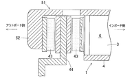
- FIG. 7 is a partially cutaway cross-sectional view of the electric brake device including any one of the electric linear actuators 1 described above.
- the electric brake device includes any one of the electric linear actuator 1, a brake rotor 44 that is a rotating member that rotates integrally with the wheel, and a friction pad 43 that generates a braking force in contact with the brake rotor 44. And a control device (not shown) for controlling the electric linear actuator.
- the vehicle is provided with calipers 51 so as to surround the outer peripheral side portion of the brake rotor 44.
- the caliper 51 is provided integrally with the housing 4 of the electric linear actuator 1.
- a claw 52 is provided at the end of the caliper 51 on the outboard side.
- the claw portion 52 faces the side surface of the brake rotor 44 on the outboard side in the axial direction.
- the claw portion 52 supports the friction pad 43 on the outboard side.
- the inboard friction pad 43 is supported on the outboard side end of the linear motion portion 6 of the linear motion mechanism 3.
- the friction pad 43 faces the side surface on the inboard side of the brake rotor 44 in the axial direction.
- the electric linear actuator 1 drives the friction pad 43 to contact or separate from the brake rotor 44.
- a mount (not shown) is supported by a knuckle (not shown) in the vehicle.
- a pair of pin support pieces (not shown) are provided at both longitudinal ends of the mount.
- a slide pin (not shown) extending parallel to the axial direction is provided at each end portion of the pin support pieces.
- a caliper 51 is supported by these slide pins so as to be slidable in the axial direction.
- the control unit CU controls the rotation of the electric motor of the electric linear actuator 1 according to the amount of operation of a brake pedal (not shown).
- a brake pedal not shown.
- the friction pad 43 on the inboard side contacts the brake rotor 44 by driving the electric linear actuator 1 and presses the brake rotor 44 in the axial direction.
- the caliper 51 slides to the inboard side by the reaction force of the pressing force.
- the friction pad 43 on the outboard side supported by the claw portion 52 of the caliper 51 contacts the brake rotor 44.
- a braking force is applied to the brake rotor 44 by strongly holding the brake rotor 44 from both sides in the axial direction by the friction pads 43 on the outboard side and the inboard side.
- the electric brake device can be mounted on a vehicle in which the space for mounting the electric linear actuator 1 is extremely limited. Therefore, the versatility of the electric brake device can be enhanced, and the electric brake device can be mounted on various vehicles.
- the rotor is preferable when the permanent magnet is held by a holding portion made of a non-magnetic material, with less loss, but the permanent magnet can also be held by a holding portion made of a magnetic material.
- the rotor may have a structure in which a single magnet magnetized on a plurality of axial magnetic poles is directly fixed to the rotation input / output shaft without using a holding portion.
- the permanent magnet of the rotor is a magnet that penetrates in the axial direction and both sides of the magnetic pole are used as interlinkage magnetic fluxes, the volume of the magnet, the dimensions of the motor, and the number of parts can be reduced. However, it may be preferable to use a structure in which magnets are bonded to both sides of a magnetic body to improve heat resistance.
- the electric motor can take the configuration of a reluctance motor using an iron core whose stator inductance changes as the rotor rotates, for example.
- various screw mechanisms such as a ball screw, a mechanism using an inclination of a ball ramp, etc. can be used in addition to the planetary roller.
- the thrust bearings of each embodiment are arranged assuming an operation of pressing an object by an electric linear actuator, but arranged so as to hold a load against the opposite side of the illustrated example, An actuator that applies a tensile load can also be configured.
- the neutral point in the parallel star connection may be provided separately for each circuit as shown in FIG. 3, or one neutral point connecting the whole may be provided.
- a delta connection can be configured, or a wiring mechanism connected in series can be used.
- the stator 7 is used in the order of U phase-U phase-V phase-V phase-W phase-W phase in order to use the flux linkage on the outer diameter side.
- a plurality of coils adjacent to each other in the circumferential direction may be arranged in the same phase.
- the coils adjacent in the circumferential direction may be arranged in different phases in the order of U phase-V phase-W phase-U phase-V phase-W phase.
- the coil applied to the electric linear actuator concentrated winding capable of reducing the winding dimension is considered suitable, but a distributed winding configuration may be adopted.
- the molding method and arrangement of the wiring are appropriately designed according to the shape of the housing and the like.
- a configuration necessary for application of the electric linear actuator such as a motor angle sensor that detects a motor angle, a thermistor, and wiring components of each electrical system, is appropriately provided.
- SYMBOLS 1 Electric linear actuator 2 ... Electric motor 3 ... Linear motion mechanism 4 ... Housing 5 ... Rotary input / output shaft 6 ... Linear motion part 7 ... Stator 7A, 7B ... 1st, 2nd excitation mechanism 8 ... Rotor 11 ... Coil 11A, 11B ... 1st, 2nd coil (flat wire coil) 11U, 11V, 11W ... Coil groups 53, 54 ... First and second coil terminals 53a, 54a ... Extension 55 ... Wiring mechanism 56 ... Neutral point CU ... Control device
Abstract
Provided is an electric linear actuator such that a reduction in installation space and a reduction in cost can be achieved. This electric linear actuator comprises an electric motor that is an axial gap motor which is provided with a stator (7) and a rotor which are arranged so that the direction of magnetic poles generating interlinkage magnetic flux contributing to torque becomes parallel to the rotation axis (L1) of the electric motor. Furthermore, a linear mechanism and the electric motor are arranged adjacent to each other on the same axis, which is the axis of the rotary input/output shaft of the linear mechanism. First and second coil terminals (53), (54) have extension portions (53a), (54b) extending towards the outer diameter in the radial direction of the rotation axis (L1), the extension portions (53a), (54a) being electrically connected to a control device through a wiring mechanism.
Description
本出願は、2016年7月8日出願の特願2016-135816の優先権を主張するものであり、その全体を参照により本願の一部をなすものとして引用する。
This application claims the priority of Japanese Patent Application No. 2016-135816 filed on July 8, 2016, and is incorporated herein by reference in its entirety.
この発明は、例えば、電動ブレーキ装置に適用される電動式直動アクチュエータに関する。
The present invention relates to, for example, an electric linear actuator applied to an electric brake device.
電動アクチュエータおよび電動モータが、以下の文献に提案されている。
1.直動部の外周に、この直動部と同軸に電動モータを配置した電動ディスクブレーキ装置(特許文献1)。
2.電動モータを直動機構の回転軸と平行で該回転軸と異なる軸に配置した電動ブレーキ装置(特許文献2)。
3.8極9スロットのダブルステータ式のアキシアルギャップモータ(特許文献3)。 Electric actuators and electric motors have been proposed in the following documents.
1. An electric disc brake device in which an electric motor is arranged coaxially with the linear motion part on the outer periphery of the linear motion part (Patent Document 1).
2. An electric brake device in which an electric motor is arranged on an axis parallel to the rotation axis of the linear motion mechanism and different from the rotation axis (Patent Document 2).
3. A 8-pole, 9-slot double stator type axial gap motor (Patent Document 3).
特許文献1~2に記載のような電動式直動アクチュエータを用いた電動ブレーキ装置は、一般に車両への搭載スペースが極めて限られており、可能な限り省スペースで機能を実現する必要がある。また、例えばアンチロックブレーキシステム(Antilock Brake System:略称ABS)に代表される車輪速制御等において、電動ブレーキは、高速・高精度なブレーキ力制御が求められる。
In general, an electric brake device using an electric linear actuator as described in Patent Documents 1 and 2 has a very limited space for mounting on a vehicle, and it is necessary to realize a function with as little space as possible. For example, in wheel speed control represented by an anti-lock brake system (abbreviated as ABS), an electric brake is required to have high-speed and high-precision brake force control.
例えば特許文献1のような、アクチュエータの外周に電動モータを配置する構造では、電動モータのロータ径が大きくなるため、慣性モーメントが増大し、応答性および制御精度を損なう場合がある。あるいは、ロータの回転に必要な運動エネルギーは慣性モーメントに比例するため、高速な応答を実現するために瞬時最大の消費電力が増大し、電力を供給する電源装置のコストが高くなる可能性がある。また、例えば電動ディスクブレーキ装置のように、アクチュエータの加圧対象物が摩擦パッドのように極めて高温になる場合、電動モータが熱源に近いため、耐久性が問題となる可能性がある。
For example, in a structure in which an electric motor is arranged on the outer periphery of an actuator as in Patent Document 1, since the rotor diameter of the electric motor is increased, the moment of inertia increases, and the response and control accuracy may be impaired. Alternatively, since the kinetic energy necessary for rotating the rotor is proportional to the moment of inertia, the instantaneous maximum power consumption increases in order to achieve a high-speed response, which may increase the cost of the power supply device that supplies the power. . Further, when the pressure object of the actuator becomes extremely high like a friction pad as in an electric disc brake device, for example, durability may be a problem because the electric motor is close to a heat source.
例えば特許文献2のような、電動モータと直動アクチュエータとを平行に配置する場合、一般に電動モータおよび直動アクチュエータの外観は円筒形状となることが多く、二つの円筒が隣接するため、隙間に一定量のデッドスペースが生じてしまう可能性がある。また電動モータと直動アクチュエータとの間に平行歯車のような連結機構が要求スペックによらず必要となり、コスト増となる可能性がある。その他、電動モータと直動アクチュエータそれぞれに支持構造が必要となるため、スペースおよびコストが問題になる場合がある。
For example, when an electric motor and a linear actuator are arranged in parallel as in Patent Document 2, generally, the external appearance of the electric motor and the linear actuator is often cylindrical, and the two cylinders are adjacent to each other. A certain amount of dead space may occur. Further, a connection mechanism such as a parallel gear is required between the electric motor and the linear actuator regardless of the required specifications, which may increase the cost. In addition, since a support structure is required for each of the electric motor and the linear motion actuator, space and cost may be a problem.
省スペースで高トルクを実現するモータ構造として、例えば特許文献3に示すようなアキシアルギャップ式同期モータが知られている。しかしながら、アキシアルギャップモータは一般に径方向寸法が大きくなるため、前記特許文献1または特許文献2の構造を採ると、搭載スペースが増大してしまう可能性がある。
As an example of a motor structure that realizes high torque in a small space, an axial gap type synchronous motor as shown in Patent Document 3, for example, is known. However, since an axial gap motor generally has a large radial dimension, using the structure of Patent Document 1 or Patent Document 2 may increase the mounting space.
この発明の目的は、搭載スペースの低減およびコスト低減を図ることができる電動式直動アクチュエータを提供することである。
An object of the present invention is to provide an electric linear actuator that can reduce the mounting space and cost.
この発明の電動式直動アクチュエータは、電動モータと、回転入出力軸を有し該回転入出力軸を介してこの電動モータの回転運動を直動部の直進運動に変換する直動機構と、この直動機構を保持するハウジングと、前記電動モータを制御する制御装置と、を備える電動式直動アクチュエータであって、
前記直動機構と前記電動モータとが、前記直動機構の前記回転入出力軸の軸心となる同一の軸心上に並んで配置され、
前記電動モータは、トルクに寄与する鎖交磁束を発生する磁極の向きが、前記電動モータにおける回転軸と平行となるように配置された固定子および回転子を備え、
前記固定子は、前記電動モータに通電する電流を前記鎖交磁束に変換するコイルを含む励磁機構を備え、
さらに、
前記コイルと前記制御装置とを電気的に接続する配線機構を備え、
前記コイルの巻線の両端部のうち、いずれか一方または両方の端部が前記回転軸における径方向に延長された延長部分を有し、この延長部分が前記配線機構に接続されている。 The electric linear actuator of the present invention includes an electric motor, a linear motion mechanism that has a rotational input / output shaft and converts the rotational motion of the electric motor to the linear motion of the linear motion portion via the rotational input / output shaft, An electric linear actuator comprising a housing that holds the linear motion mechanism and a control device that controls the electric motor,
The linear motion mechanism and the electric motor are arranged side by side on the same axis serving as the axis of the rotation input / output shaft of the linear motion mechanism,
The electric motor includes a stator and a rotor arranged such that the direction of the magnetic poles that generate the interlinkage magnetic flux contributing to the torque is parallel to the rotation axis of the electric motor,
The stator includes an excitation mechanism including a coil that converts a current to be supplied to the electric motor into the linkage flux.
further,
A wiring mechanism for electrically connecting the coil and the control device;
One or both of the ends of the winding of the coil have an extended portion that extends in the radial direction of the rotating shaft, and the extended portion is connected to the wiring mechanism.
この構成によると、電動モータは、トルクに寄与する鎖交磁束を発生する磁極の向きが、電動モータにおける回転軸と平行となるように配置された固定子および回転子を備えるいわゆるアキシアルギャップモータである。さらに直動機構と電動モータとが、直動機構の回転入出力軸の軸心となる同一の軸心上に並んで配置されている。このため、電動モータと直動アクチュエータとを平行に配置する構造等に比べて、無効なスペースが少なく省スペース化を図ることができ、且つ、慣性モーメントが小さく高応答な電動式直動アクチュエータを実現できる。
According to this configuration, the electric motor is a so-called axial gap motor including a stator and a rotor arranged so that the direction of the magnetic poles that generate the interlinkage magnetic flux contributing to the torque is parallel to the rotation axis of the electric motor. is there. Further, the linear motion mechanism and the electric motor are arranged side by side on the same axis that is the axis of the rotation input / output shaft of the linear motion mechanism. Therefore, compared to a structure in which the electric motor and the direct acting actuator are arranged in parallel, an electric linear acting actuator that has a small amount of invalid space and can save space, and has a small moment of inertia and high response. realizable.
固定子は励磁機構を備え、この励磁機構はコイルを含む。制御装置により電動モータに電流が通電されることで、コイルは前記電流を前記鎖交磁束に変換する。配線機構は、コイルと制御装置とを電気的に接続する。コイルの巻線の両端部(コイル端子)のうち、いずれか一方または両方の端部が前記回転軸における径方向に延長された延長部分を有し、この延長部分が配線機構に接続されている。このようにコイル端子が前記回転軸における径方向に延長された延長部分を有することで、電動モータのコイルと制御装置との接続が容易となり、コスト低減と省スペース化を図るうえで有利となる。したがって、搭載スペースの低減およびコスト低減を図ることができる。
The stator is equipped with an excitation mechanism, which includes a coil. When a current is passed through the electric motor by the control device, the coil converts the current into the linkage flux. The wiring mechanism electrically connects the coil and the control device. Either or both ends of the coil windings (coil terminals) have an extended portion extending in the radial direction of the rotating shaft, and the extended portion is connected to the wiring mechanism. . In this way, the coil terminal has an extended portion extending in the radial direction on the rotating shaft, which facilitates the connection between the coil of the electric motor and the control device, which is advantageous for cost reduction and space saving. . Therefore, it is possible to reduce the mounting space and cost.
前記コイルを形成する前記巻線は、この巻線の軸心を含む平面で切断して見た断面が長方形状であり、この長方形状の巻線の前記断面における長手方向が前記回転軸に直交し、且つ、前記長方形状の巻線の前記断面における短手方向が前記回転軸と平行となるように配置され、前記巻線は前記短手方向に積層されるように巻回されていてもよい。
The winding forming the coil has a rectangular cross section viewed by cutting along a plane including the axis of the winding, and the longitudinal direction of the rectangular winding is orthogonal to the rotation axis. And the short winding direction in the cross section of the rectangular winding is arranged to be parallel to the rotation axis, and the winding is wound so as to be laminated in the short direction. Good.
前記巻線の両端部のうち、いずれか一方の端部の延長部分が前記回転軸における径方向外径側に延長され、他方の端部の延長部分が前記回転軸における径方向内径側に延長されているものであってもよい。
Of the both ends of the winding, an extended portion of one end is extended to the radially outer diameter side of the rotating shaft, and an extended portion of the other end is extended to the radially inner diameter side of the rotating shaft. It may be what has been done.
前記巻線は、この巻線の軸心を含む平面で切断して見た断面が長方形状である。このような断面が長方形状の巻線として、例えば、平角線を適用し得る。また巻線が前記短手方向に積層されるように巻回されているため、電動モータは、前記回転軸の軸方向にコンパクト化することができ、省スペース化をより図ることができる。また前記平角線を用いて一層に巻線されたコイルを用いると、放熱性が高く、巻線の断面に占める導体の割合である「占積率」に優れた固定子を構成できる。
The winding has a rectangular cross section viewed by cutting along a plane including the axis of the winding. As such a winding having a rectangular cross section, for example, a flat wire can be applied. Further, since the winding is wound so as to be laminated in the short direction, the electric motor can be made compact in the axial direction of the rotating shaft, and space saving can be further achieved. Further, when a coil wound in one layer using the rectangular wire is used, a stator having high heat dissipation and excellent “space factor” which is a ratio of conductors in the cross section of the winding can be configured.
巻線の両端部のうち、いずれか一方の端部の延長部分が回転軸における径方向外径側に延長され、他方の端部の延長部分が回転軸における径方向内径側に延長されている場合には、配線長を低減することが可能となる。これにより、損失の低減および材料費の削減において好適となる。
Of the both ends of the winding, the extension of one of the ends is extended to the radially outer diameter side of the rotating shaft, and the extension of the other end is extended to the radially inner diameter side of the rotating shaft. In this case, the wiring length can be reduced. Thereby, it becomes suitable in reduction of loss and reduction of material cost.
前記コイルを形成する前記巻線は、この巻線の軸心に平行な平面で切断して見た断面が長方形状であり、この長方形状の巻線の前記断面における長手方向が前記回転軸に平行であり、且つ、前記長方形状の巻線の前記断面における短手方向が前記回転軸と直交するように配置され、前記巻線は前記短手方向に積層されるように巻回されているものであってもよい。この場合の巻線として、例えば、平角線を適用し得る。また巻線が前記短手方向に積層されるように巻回されているため、巻数にもよるが、例えば、ハウジング等に固定子をコンパクトに収めることが可能となる。
The winding forming the coil has a rectangular cross section viewed by cutting along a plane parallel to the axial center of the winding, and the longitudinal direction of the cross section of the rectangular winding is the rotation axis. Parallel and arranged so that the short direction in the cross section of the rectangular winding is orthogonal to the rotation axis, and the winding is wound so as to be stacked in the short direction It may be a thing. As the winding in this case, for example, a rectangular wire can be applied. Further, since the windings are wound so as to be laminated in the short direction, the stator can be compactly accommodated in a housing or the like, for example, depending on the number of turns.
前記巻線の両端部のうち、いずれか一方の端部の延長部分が前記回転軸における径方向外径側に延長され、他方の端部の延長部分が前記回転軸の軸方向に対し平行に延長されていてもよい。この構成において、前記他方の端部の延長部分がいわゆる中性点に接続される場合には、配線長を低減することが可能となる。これにより、損失の低減および材料費の削減を図ることが可能となる。
Of the both ends of the winding, an extended portion of one end is extended to the radially outer diameter side of the rotating shaft, and an extended portion of the other end is parallel to the axial direction of the rotating shaft. It may be extended. In this configuration, when the extended portion of the other end is connected to a so-called neutral point, the wiring length can be reduced. This makes it possible to reduce loss and material cost.
前記励磁機構が三相交流電流の各相に対応するコイル群を有し、
前記配線機構は、
前記コイルが少なくとも一つ以上の中性点を有するようスター結線され、
前記巻線の両端部のうち、前記他方の端部の延長部分が、前記中性点に接続され、
前記巻線の両端部のうち、前記一方の端部の延長部分が、前記三相交流電流を制御する前記制御装置と接続されているものであってもよい。 The excitation mechanism has a coil group corresponding to each phase of a three-phase alternating current,
The wiring mechanism is
The coil is star-connected to have at least one neutral point;
Of the both ends of the winding, the extension of the other end is connected to the neutral point,
The extension part of said one edge part may be connected with the said control apparatus which controls the said three-phase alternating current among the both ends of the said coil | winding.
この構成によると、前記径方向内径側または前記軸方向に対し平行に延長されている他方の端部の延長部分が、前記中性点に接続されることで、例えば、デルタ結線を構成するものよりも、配線長を確実に低減でき、損失の低減および材料費の削減を図ることができる。径方向外径側に延長されている一方の端部の延長部分が、三相交流電流を制御する制御装置と接続されているため、コイルと制御装置との電気的な接続を、コネクタ等を介して簡単に行うことができる。
According to this configuration, the extension portion of the other end portion extending in parallel to the radial inner diameter side or the axial direction is connected to the neutral point, for example, constituting a delta connection As a result, the wiring length can be surely reduced, and loss and material costs can be reduced. Since the extended part of one end that is extended to the radially outer diameter side is connected to the control device that controls the three-phase alternating current, the electrical connection between the coil and the control device can be made with a connector, etc. Can be done easily.
請求の範囲および/または明細書および/または図面に開示された少なくとも2つの構成のどのような組合せも、この発明に含まれる。特に、請求の範囲の各請求項の2つ以上のどのような組合せも、この発明に含まれる。
Any combination of at least two configurations disclosed in the claims and / or the specification and / or the drawings is included in the present invention. In particular, any combination of two or more of each claim in the claims is included in the invention.
この発明は、添付の図面を参考にした以下の好適な実施形態の説明から、より明瞭に理解されるであろう。しかしながら、実施形態および図面は単なる図示および説明のためのものであり、この発明の範囲を定めるために利用されるべきものではない。この発明の範囲は添付の請求の範囲によって定まる。添付図面において、複数の図面における同一の符号は、同一または相当する部分を示す。
The present invention will be understood more clearly from the following description of preferred embodiments with reference to the accompanying drawings. However, the embodiments and drawings are for illustration and description only and should not be used to define the scope of the present invention. The scope of the invention is defined by the appended claims. In the accompanying drawings, the same reference numerals in a plurality of drawings indicate the same or corresponding parts.
この発明の一実施形態に係る電動式直動アクチュエータを図1ないし図3と共に説明する。この電動式直動アクチュエータは、例えば、車両に搭載される電動ブレーキ装置(後述する)に適用される。図1に示すように、この電動式直動アクチュエータ1は、電動モータ2と、直動機構3とを軸方向に直列に接続したアクチュエータである。直動機構3と電動モータ2とは、直動機構3の回転入出力軸5の軸心となる同一の軸心上に並んで配置されている。この電動式直動アクチュエータ1は、直動アクチュエータ本体AHと、電動モータ2を制御する制御装置CUとを備える。
An electric linear actuator according to an embodiment of the present invention will be described with reference to FIGS. This electric linear actuator is applied to, for example, an electric brake device (described later) mounted on a vehicle. As shown in FIG. 1, the electric linear actuator 1 is an actuator in which an electric motor 2 and a linear mechanism 3 are connected in series in the axial direction. The linear motion mechanism 3 and the electric motor 2 are arranged side by side on the same axis serving as the axis of the rotation input / output shaft 5 of the linear motion mechanism 3. The electric linear actuator 1 includes a linear actuator main body AH and a control unit CU that controls the electric motor 2.
直動アクチュエータ本体AHは、電動モータ2と、直動機構3と、ハウジング4とを備える。この例の電動モータ2は、ダブルステータ型のアキシアルギャップモータである。直動機構3は、直動部6を有し、回転入出力軸5を介して、電動モータ2の回転運動を直動部6の直進運動に変換する。ハウジング4は、直動機構3および電動モータ2を保持する。なお、簡略化のため配線等の一部構造は省略している。
The linear motion actuator main body AH includes an electric motor 2, a linear motion mechanism 3, and a housing 4. The electric motor 2 of this example is a double stator type axial gap motor. The linear motion mechanism 3 has a linear motion portion 6 and converts the rotational motion of the electric motor 2 into the linear motion of the linear motion portion 6 via the rotation input / output shaft 5. The housing 4 holds the linear motion mechanism 3 and the electric motor 2. For simplification, some structures such as wiring are omitted.
電動モータ2について説明する。電動モータ2は、トルクに寄与する鎖交磁束を発生する磁極の向きが、この電動モータ2における回転軸と平行に配置された固定子7および回転子8を備えた、いわゆるアキシアルギャップ型である。固定子7は、ハウジング4に対して静的に保持される。回転子8は、直動機構3の回転入出力軸5に対して静的に保持され、間隔を隔てて配置された固定子7との鎖交磁束により回転トルクを発生する。回転子8は、この回転子8の軸方向の両面にそれぞれトルク発生面を有する界磁機構である。前記各「静的に」とは、すきま等の影響を除いて概ね運動が同期する(換言すれば、相対的に拘束された)関係を意味する。
The electric motor 2 will be described. The electric motor 2 is a so-called axial gap type including a stator 7 and a rotor 8 in which the direction of the magnetic poles that generate the interlinkage magnetic flux contributing to the torque is arranged in parallel with the rotation axis of the electric motor 2. . The stator 7 is held statically with respect to the housing 4. The rotor 8 is statically held with respect to the rotation input / output shaft 5 of the linear motion mechanism 3, and generates a rotational torque by the interlinkage magnetic flux with the stator 7 arranged at an interval. The rotor 8 is a field mechanism having torque generating surfaces on both axial surfaces of the rotor 8. Each “statically” means a relationship in which the motions are generally synchronized (in other words, relatively constrained) excluding the influence of a clearance or the like.
円筒形状のハウジング4内に、電動モータ2が設けられている。ハウジング4内には、直動機構3の大部分を収容する直動機構収容部4aと、電動モータ2を収容するモータ収容部4bと、これら直動機構収容部4a,モータ収容部4bを仕切る隔壁4cとが設けられている。モータ収容部4bは、ハウジング4内における軸方向一端側に設けられ、直動機構収容部4aは、ハウジング4内における軸方向他端側に設けられている。
An electric motor 2 is provided in a cylindrical housing 4. In the housing 4, a linear motion mechanism accommodating portion 4a that accommodates most of the linear motion mechanism 3, a motor accommodating portion 4b that accommodates the electric motor 2, and the linear motion mechanism accommodating portion 4a and the motor accommodating portion 4b are partitioned. A partition wall 4c is provided. The motor housing portion 4 b is provided on one axial end side in the housing 4, and the linear motion mechanism housing portion 4 a is provided on the other axial end side in the housing 4.
隔壁4cは、隔壁本体部4caと、ボス部4cbとを有する。隔壁本体部4caは、回転入出力軸5の軸方向に対して垂直に設けられ、直動機構収容部4aからモータ収容部4bへ回転入出力軸5が挿入される貫通孔が形成されている。ボス部4cbは、隔壁本体部4caの内径側端部から軸方向(モータ収容部4b側)に所定距離延びる円筒状である。ハウジング4のモータ収容部4bに電動モータ2が収容された状態で、ハウジング4における電動モータ2側(前記軸方向一端側)の開口端を塞ぐモータカバー45が設けられている。
The partition 4c has a partition main body 4ca and a boss 4cb. The partition wall main body 4ca is provided perpendicular to the axial direction of the rotation input / output shaft 5 and has a through hole into which the rotation input / output shaft 5 is inserted from the linear motion mechanism housing portion 4a to the motor housing portion 4b. . The boss portion 4cb has a cylindrical shape extending a predetermined distance in the axial direction (motor housing portion 4b side) from the inner diameter side end of the partition wall main body portion 4ca. A motor cover 45 is provided that closes the opening end of the housing 4 on the side of the electric motor 2 (one end side in the axial direction) in a state where the electric motor 2 is housed in the motor housing portion 4 b of the housing 4.
固定子7は、回転子8の軸方向の両側にそれぞれ対向して配置される一対の励磁機構7A,7Bを備えている。これら励磁機構7A,7Bのうち、隔壁4c側に在る一方を第1の励磁機構7A、モータカバー45側に在る他方を第2の励磁機構7Bとする。第1の励磁機構7Aは、磁性体コア10A、バックヨーク9A、および第1のコイル11Aを有する。第2の励磁機構7Bは、磁性体コア10B、バックヨーク9B、および第2のコイル11Bを有する。
The stator 7 is provided with a pair of excitation mechanisms 7A and 7B arranged to face both sides of the rotor 8 in the axial direction. Of these excitation mechanisms 7A and 7B, one on the partition 4c side is the first excitation mechanism 7A, and the other on the motor cover 45 side is the second excitation mechanism 7B. The first excitation mechanism 7A has a magnetic core 10A, a back yoke 9A, and a first coil 11A. The second excitation mechanism 7B has a magnetic core 10B, a back yoke 9B, and a second coil 11B.
第1の励磁機構7Aについて説明すると、ハウジング4内のモータ収容部4bにおいて、隔壁4cに当接するようにバックヨーク9Aが設けられ、このバックヨーク9Aから軸方向に突出する磁性体コア10Aが設けられている。この磁性体コア10Aは、円周方向一定間隔おきに複数設けられている。磁性体コア10Aは、例えば、積層鋼板または圧粉磁心等から成る。各磁性体コア10Aに第1のコイル11Aがそれぞれ巻回されている。第1のコイル11Aは、電動モータ2に通電する電流を前記鎖交磁束に変換する。
The first excitation mechanism 7A will be described. In the motor accommodating portion 4b in the housing 4, a back yoke 9A is provided so as to abut against the partition wall 4c, and a magnetic core 10A protruding in the axial direction from the back yoke 9A is provided. It has been. A plurality of the magnetic cores 10A are provided at regular intervals in the circumferential direction. The magnetic core 10A is made of, for example, a laminated steel plate or a dust core. A first coil 11A is wound around each magnetic core 10A. 11 A of 1st coils convert the electric current which energizes the electric motor 2 into the said linkage flux.
第2の励磁機構7Bについて説明すると、ハウジング4内のモータ収容部4bにおいて、モータカバー45に当接するようにバックヨーク9Bが設けられ、このバックヨーク9Bから軸方向に突出する磁性体コア10Bが設けられている。この磁性体コア10Bも、磁性体コア10Aと同様に円周方向一定間隔おきに複数設けられている。各磁性体コア10Bに第2のコイル11Bがそれぞれ巻回されている。
The second excitation mechanism 7B will be described. In the motor housing portion 4b in the housing 4, a back yoke 9B is provided so as to contact the motor cover 45, and a magnetic core 10B protruding in the axial direction from the back yoke 9B is provided. Is provided. A plurality of magnetic cores 10B are also provided at regular intervals in the circumferential direction, similarly to the magnetic core 10A. A second coil 11B is wound around each magnetic core 10B.
磁性体コア10Bおよび第2のコイル11Bのその他の構成は、前述の磁性体コア10Aおよび第1のコイル11Aと同様の構成である。積層鋼板または圧粉磁心等から成る磁性体コア10A,磁性体コア10Bを用いると、単位銅損あたりのトルクが向上するため好適と考えられる。但し、磁性体コアを用いず、部品コストの低減およびトルク変動の低減に効果がある空芯コイルにすることもできる。
Other configurations of the magnetic core 10B and the second coil 11B are the same as those of the magnetic core 10A and the first coil 11A. It is considered preferable to use the magnetic core 10A and magnetic core 10B made of laminated steel plates or dust cores because the torque per unit copper loss is improved. However, an air-core coil that is effective in reducing component costs and torque fluctuation can be used without using a magnetic core.
固定子構造等について説明する。図2(A)は、図1の電動式直動アクチュエータ1に用いられるアキシアルギャップモータの固定子7全体の概略形状を示す斜視図である。同図2(A)中、円筒状のボス部4cbの中心軸L1が、同電動式直動アクチュエータ1の回転軸に対応する。なお、以下の固定子構造および配線機構の説明において、固定子7の第1,第2の励磁機構7A,7B(図1)が共に同様の構成となっているため、第1の励磁機構7Aについて主に説明し、第2の励磁機構7B(図1)については適宜省略する。
The stator structure will be explained. FIG. 2A is a perspective view showing a schematic shape of the entire stator 7 of the axial gap motor used in the electric linear actuator 1 of FIG. In FIG. 2A, the central axis L1 of the cylindrical boss 4cb corresponds to the rotation axis of the electric linear actuator 1. In the following description of the stator structure and wiring mechanism, the first and second excitation mechanisms 7A and 7B (FIG. 1) of the stator 7 have the same configuration, and therefore the first excitation mechanism 7A. The second excitation mechanism 7B (FIG. 1) will be omitted as appropriate.
図2(A)では、固定子7の構造として、9スロットの平角線コイルを設ける例を示す。このスロット数は、9スロットに限定されるものではなく設計に応じて適宜定められる。また、本図のように平角線を用いて一層に巻線されたコイル11Aを用いると、放熱性が高く、巻線の断面に占める導体の割合である「占積率」に優れた固定子7を構成できるため、好適と考えられる。
FIG. 2A shows an example in which a 9-slot rectangular wire coil is provided as the structure of the stator 7. The number of slots is not limited to nine slots, but is determined appropriately according to the design. In addition, when a coil 11A wound in a single layer using a rectangular wire as shown in this figure is used, the stator has high heat dissipation and excellent “space factor”, which is the ratio of the conductor to the cross section of the winding. 7 can be configured, which is considered preferable.
図2(B)に示すように、平角線コイル11Aを形成する巻線の両端部(第1,第2コイル端子53,54)は、いずれも中心軸(回転軸)L1の径方向外径側に延長された延長部分53a,54aを有する。図3に示すように、これら延長部分53a,54aは配線機構55を介して制御装置CUに電気的に接続されている。但し、各磁性体コア10Aに巻回されたコイルの第1,第2コイル端子53,54の延長部分53a,54aは、互いに異なる位相に配置される。すなわち第1コイル端子53の延長部分53aは、例えば図2(B)に示す平面視で角丸の略二等辺三角形状である各磁性体コア10Aの一辺から延長した接線方向で、且つ、径方向外径側に延長されている。第2コイル端子54の延長部分54aは、各磁性体コア10Aにおける前記一辺に隣り合う他の一辺から延長した接線方向で、且つ、径方向外径側に延長されている。
As shown in FIG. 2B, both end portions (first and second coil terminals 53 and 54) of the winding forming the rectangular wire coil 11A are both radially outer diameters of the central axis (rotating shaft) L1. It has extension parts 53a and 54a extended to the side. As shown in FIG. 3, these extended portions 53 a and 54 a are electrically connected to the control unit CU via the wiring mechanism 55. However, the extended portions 53a and 54a of the first and second coil terminals 53 and 54 of the coil wound around each magnetic core 10A are arranged in different phases. That is, the extended portion 53a of the first coil terminal 53 has a tangential direction extending from one side of each magnetic core 10A having a substantially isosceles triangular shape with rounded corners in a plan view shown in FIG. It is extended to the direction outer diameter side. The extended portion 54a of the second coil terminal 54 extends in the tangential direction extending from the other side adjacent to the one side in each magnetic core 10A and on the radially outer diameter side.
図3は、配線機構55の例を示す図である。この例では、スター結線された三相交流同期モータ回路を並列に構成する例を示す。図3に示すように、固定子7を構成する図2(A)の第1の励磁機構7Aは、三相交流電流の各相(U相,V相,W相)に対応するコイル群11U,11V,11Wを有する。配線機構55は、前記回路毎に、それぞれ中性点56を有するようスター結線され、第1のコイル端子53の延長部分53aが、例えばバスバー57を介して、中性点56に接続されている。この中性点56は、前記回路毎に分離して設けられている。また配線機構55は、第2のコイル端子54の延長部分54aが、例えばバスバー58を介して、前記三相交流電流を制御する制御装置CUと接続されている。
FIG. 3 is a diagram illustrating an example of the wiring mechanism 55. In this example, a star-connected three-phase AC synchronous motor circuit is configured in parallel. As shown in FIG. 3, the first excitation mechanism 7A of FIG. 2A constituting the stator 7 is a coil group 11U corresponding to each phase (U phase, V phase, W phase) of the three-phase alternating current. , 11V, 11W. The wiring mechanism 55 is star-connected so as to have a neutral point 56 for each circuit, and the extended portion 53a of the first coil terminal 53 is connected to the neutral point 56 through a bus bar 57, for example. . The neutral point 56 is provided separately for each circuit. In the wiring mechanism 55, the extended portion 54 a of the second coil terminal 54 is connected to the control unit CU that controls the three-phase alternating current via, for example, a bus bar 58.
前記各バスバー57,58は、互いに電気的に絶縁されて、例えば、ハウジング4に含まれる固定子用ハウジング(内周、外周の端縁が肉厚である略中空円板状の主部を有している)の外周部に、各々、円環状にインサート成形されている。第2のコイル端子54の延長部分54aがバスバー58に接続され、このバスバー58はコネクタ59の端子に所定の関係を持って接続されている。コネクタ59は、ハウジング4の外周部から半径方向外方に突出するように設けられている。バスバー58はコネクタ59を介して制御装置CUと接続されている。このようにバスバー58がコネクタ59を介して制御装置CUと接続される構造とすると、省スペースで信頼性の高い固定子7および配線機構55が実現できて好適と考えられる。但し、この構造に限定されるものではない。
Each of the bus bars 57 and 58 is electrically insulated from each other, and has, for example, a stator housing (a substantially hollow disk-shaped main portion whose inner and outer edges are thick) included in the housing 4. Are formed in an annular shape on the outer periphery of each of them. An extension 54 a of the second coil terminal 54 is connected to a bus bar 58, and the bus bar 58 is connected to a terminal of the connector 59 with a predetermined relationship. The connector 59 is provided so as to protrude radially outward from the outer peripheral portion of the housing 4. The bus bar 58 is connected to the control unit CU via a connector 59. If the bus bar 58 is connected to the control unit CU via the connector 59 in this way, it can be considered that the space-saving and highly reliable stator 7 and the wiring mechanism 55 can be realized. However, it is not limited to this structure.
例えば、バスバー57,58が互いに電気的に絶縁されて、インサートされた別の部材を配線部材としてハウジング4に別途設ける構成とすることもできる。コイル材またはハーネスを用いて配線を行い、ワニス等で固定する構造としてもよい。また、例えば、制御基板をモータ近傍に配置する機電一体構造とする場合等においては、コネクタ59を用いず、バスバーの端部を端子として露出させる構造としてもよいし、例えば、ハウジング4の内部でハーネスに結線し、ハーネスをそのままハウジング4の外部に引出す構造としてもよい。
For example, the bus bars 57 and 58 may be electrically insulated from each other, and another member inserted may be separately provided in the housing 4 as a wiring member. It is good also as a structure which performs wiring using a coil material or a harness, and fixes with a varnish etc. Further, for example, in the case of an electromechanical integrated structure in which the control board is disposed in the vicinity of the motor, the connector 59 may not be used, and the end of the bus bar may be exposed as a terminal. It is good also as a structure connected to a harness and pulling out a harness as it is outside the housing 4 as it is.
図1に示すように、また図2(B)から把握できるように、平角線コイル11Aを形成する巻線は、この巻線の軸心L2(前記中心軸L1と平行)を含む平面で切断して見た断面が長方形状である。この長方形状の巻線の前記断面における長手方向が回転軸L1に直交し、且つ、前記長方形状の巻線の前記断面における短手方向が前記回転軸L1と平行となるように配置されている。この巻線は前記短手方向に積層されるように巻回されている。なお巻線は、平角線だけに限定されず、真四角線または丸線を用いることもできる。
As shown in FIG. 1 and as can be understood from FIG. 2B, the winding forming the rectangular coil 11A is cut along a plane including the axis L2 (parallel to the central axis L1) of this winding. The cross section seen is a rectangular shape. The rectangular winding is arranged such that the longitudinal direction in the cross section is perpendicular to the rotation axis L1, and the short direction in the cross section of the rectangular winding is parallel to the rotation axis L1. . The winding is wound so as to be laminated in the short direction. The winding is not limited to a rectangular wire, and a square wire or a round wire may be used.
図1に示すように、回転子8は、例えば、永久磁石8aと、この永久磁石8aを保持する保持部8bとを有する円板状の部材である。保持部8bは、例えば、樹脂またはステンレス鋼等の非磁性材料から成る。前述のように、固定子7は、第1,第2のコイル11A,11Bを含む励磁機構として構成し、回転子8は永久磁石8aを用いた界磁機構として構成し、電動モータ2を永久磁石同期電動機とすると、耐久性、トルク密度、等に優れ、電動式直動アクチュエータに好適と考えられる。
As shown in FIG. 1, the rotor 8 is a disk-shaped member having, for example, a permanent magnet 8a and a holding portion 8b that holds the permanent magnet 8a. The holding portion 8b is made of, for example, a nonmagnetic material such as resin or stainless steel. As described above, the stator 7 is configured as an excitation mechanism including the first and second coils 11A and 11B, the rotor 8 is configured as a field mechanism using the permanent magnet 8a, and the electric motor 2 is permanently set. If it is set as a magnet synchronous motor, it is excellent in durability, torque density, etc., and it is thought that it is suitable for an electric linear actuator.
回転子8は、直動機構3の回転入出力軸5の先端部分に固定されている。図1の例では、回転入出力軸5のうち、モータ収容部4bに侵入している先端部分の外周面に、回転子8が二つの止め輪24,24に挟み込まれて軸方向に位置決めされ固定されている。回転入出力軸5の先端部分の外周面には、これら二つの止め輪24,24を固定する環状溝がそれぞれ形成されている。
The rotor 8 is fixed to the tip portion of the rotation input / output shaft 5 of the linear motion mechanism 3. In the example of FIG. 1, the rotor 8 is sandwiched between two retaining rings 24, 24 and positioned in the axial direction on the outer peripheral surface of the tip portion of the rotary input / output shaft 5 that has entered the motor housing 4 b. It is fixed. On the outer peripheral surface of the tip portion of the rotary input / output shaft 5, annular grooves for fixing these two retaining rings 24, 24 are formed.
したがって、回転子8は、止め輪24,24により、回転入出力軸5に対し、第1の励磁機構7Aと第2の励磁機構7Bとの間に相当する軸方向位置に固定される。電動モータ2の回転軸は、直動機構3の回転入出力軸5に同軸に配置される。その他図示は省略するが、回転子8から回転入出力軸5へのトルク伝達を可能とする回転軸周方向の位置決め構造は、平面加工、スプライン、嵌め合い摩擦力、溶接等により実現し得る。
Therefore, the rotor 8 is fixed to the axial position corresponding to the rotation input / output shaft 5 between the first excitation mechanism 7A and the second excitation mechanism 7B by the retaining rings 24, 24. The rotation shaft of the electric motor 2 is arranged coaxially with the rotation input / output shaft 5 of the linear motion mechanism 3. Although not shown in the drawings, the positioning structure in the circumferential direction of the rotating shaft that enables torque transmission from the rotor 8 to the rotation input / output shaft 5 can be realized by plane machining, spline, fitting frictional force, welding, or the like.
直動機構3について説明する。ハウジング4内における直動機構収容部4aに、直動機構3の大部分が組み込まれている。直動機構3は、電動モータ2の出力により、後述するブレーキロータに対して制動力を負荷する。この直動機構3は、回転入出力軸5を介して電動モータ2の回転運動を直動部6の直進運動に変換する。
The linear motion mechanism 3 will be described. Most of the linear motion mechanism 3 is incorporated in the linear motion mechanism accommodating portion 4 a in the housing 4. The linear motion mechanism 3 applies a braking force to a brake rotor described later by the output of the electric motor 2. The linear motion mechanism 3 converts the rotational motion of the electric motor 2 into the linear motion of the linear motion portion 6 via the rotation input / output shaft 5.
直動機構3は、電動モータ2により回転駆動される回転入出力軸5と、この回転入出力軸5の回転運動を直進運動に変換する変換機構部31とを有する。変換機構部31は、直動部6と、軸受ケース32と、環状のスラスト板であるバックプレート33と、直動部6の直進運動に伴う軸方向の荷重に対する反作用力を保持するスラスト軸受34と、ラジアル軸受35と、キャリア36と、すべり軸受37,38と、遊星ローラ39とを有する。
The linear motion mechanism 3 includes a rotational input / output shaft 5 that is rotationally driven by the electric motor 2 and a conversion mechanism unit 31 that converts the rotational motion of the rotational input / output shaft 5 into a linear motion. The conversion mechanism portion 31 includes a linear motion portion 6, a bearing case 32, a back plate 33 that is an annular thrust plate, and a thrust bearing 34 that holds a reaction force against an axial load associated with the linear motion of the linear motion portion 6. And a radial bearing 35, a carrier 36, slide bearings 37 and 38, and a planetary roller 39.
直動機構収容部4aの内周面に、円筒状の直動部6が、回り止めされ且つ軸方向に移動自在に支持されている。直動部6の内周面には、径方向内方に突出し螺旋状に形成された螺旋突起が設けられている。この螺旋突起に複数の遊星ローラ39が噛合している。
A cylindrical linear motion portion 6 is supported on the inner peripheral surface of the linear motion mechanism accommodating portion 4a so as to be prevented from rotating and movable in the axial direction. On the inner peripheral surface of the linear motion portion 6, a spiral protrusion that protrudes inward in the radial direction and is formed in a spiral shape is provided. A plurality of planetary rollers 39 are engaged with the spiral protrusions.
直動機構収容部4aにおける直動部6の軸方向一端側に、軸受ケース32が設けられている。この軸受ケース32は、円筒状のボス部と、このボス部から径方向外方に延びるフランジ部とを有する。前記ボス部内に複数のラジアル軸受35が嵌合され、これらラジアル軸受35の内輪内径面に回転入出力軸5が嵌合されている。回転入出力軸5は、支持部材32に複数のラジアル軸受35を介して回転自在に支持される。
A bearing case 32 is provided on one end side in the axial direction of the linear motion portion 6 in the linear motion mechanism accommodating portion 4a. The bearing case 32 has a cylindrical boss portion and a flange portion extending radially outward from the boss portion. A plurality of radial bearings 35 are fitted into the boss portions, and the rotation input / output shaft 5 is fitted to the inner ring inner surface of the radial bearings 35. The rotation input / output shaft 5 is rotatably supported by the support member 32 via a plurality of radial bearings 35.
直動部6の内周には、回転入出力軸5を中心に回転可能なキャリア36が設けられている。キャリア36は、回転入出力軸5との間に嵌合されたすべり軸受37,38により、回転入出力軸5に回転自在に支持されている。回転入出力軸5の軸方向先端部分には、軸受ケース32に対して回転入出力軸5およびキャリア36の軸方向位置を拘束する止め輪40が設けられている。
A carrier 36 that can rotate around the rotation input / output shaft 5 is provided on the inner periphery of the linear motion portion 6. The carrier 36 is rotatably supported on the rotation input / output shaft 5 by slide bearings 37 and 38 fitted between the rotation input / output shaft 5. A retaining ring 40 that restricts the axial positions of the rotational input / output shaft 5 and the carrier 36 with respect to the bearing case 32 is provided at the tip portion of the rotational input / output shaft 5 in the axial direction.
キャリア36には、複数のローラ軸41が周方向に間隔を空けて設けられている。キャリア36の軸方向両端部には、それぞれ軸挿入孔が複数形成されている。各軸挿入孔は、径方向に所定距離延びる長孔から成る。各軸挿入孔に各ローラ軸41の軸方向両端部が挿入されて、これらローラ軸41が各軸挿入孔の範囲で径方向に移動自在に支持される。複数のローラ軸41における軸方向両端部には、これらローラ軸41を径方向内方に付勢する弾性リング42がそれぞれ掛け渡されている。
The carrier 36 is provided with a plurality of roller shafts 41 at intervals in the circumferential direction. A plurality of shaft insertion holes are formed at both ends of the carrier 36 in the axial direction. Each shaft insertion hole is composed of a long hole extending a predetermined distance in the radial direction. Both axial ends of each roller shaft 41 are inserted into each shaft insertion hole, and these roller shafts 41 are supported so as to be movable in the radial direction within the range of each shaft insertion hole. The elastic rings 42 that urge the roller shafts 41 radially inward are spanned at both axial ends of the plurality of roller shafts 41.
各ローラ軸41に、遊星ローラ39が回転自在に支持される。各遊星ローラ39の外周面には、直動部6の螺旋突起に噛合する円周溝または螺旋溝が形成されている。各遊星ローラ39は、回転入出力軸5の外周面と、直動部6の内周面との間に介在される。弾性リング42の付勢力により、各遊星ローラ39が回転入出力軸5の外周面に押し付けられる。電動モータ2により回転入出力軸5が回転することで、この回転入出力軸5の外周面に接触する各遊星ローラ39が接触摩擦により回転する。これにより直動部6が軸方向に移動することで、この直動部6の軸方向先端に設けられた摩擦パッド43(図7)がブレーキロータ44(図7)に対して当接または離隔する。
The planetary roller 39 is rotatably supported on each roller shaft 41. On the outer peripheral surface of each planetary roller 39, a circumferential groove or a spiral groove that meshes with the spiral protrusion of the linear motion portion 6 is formed. Each planetary roller 39 is interposed between the outer peripheral surface of the rotation input / output shaft 5 and the inner peripheral surface of the linear motion portion 6. Each planetary roller 39 is pressed against the outer peripheral surface of the rotation input / output shaft 5 by the urging force of the elastic ring 42. When the rotation input / output shaft 5 is rotated by the electric motor 2, each planetary roller 39 in contact with the outer peripheral surface of the rotation input / output shaft 5 is rotated by contact friction. As a result, the linear motion part 6 moves in the axial direction, so that the friction pad 43 (FIG. 7) provided at the tip of the linear motion part 6 in the axial direction contacts or separates from the brake rotor 44 (FIG. 7). To do.
以上説明した電動式直動アクチュエータ1によれば、電動モータ2は、トルクに寄与する鎖交磁束を発生する磁極の向きが、前記電動モータ2における回転軸と平行になるように配置された固定子7および回転子8を備えるいわゆるアキシアルギャップモータである。さらに直動機構3と電動モータ2とが、直動機構3の回転入出力軸5の軸心となる同一の軸心上に並んで配置されている。このため、電動モータと直動アクチュエータとを平行に配置する構造等に比べて、無効なスペースが少なく省スペース化を図ることができ、且つ、トルク密度の向上が図れて慣性モーメントが小さく高応答な電動式直動アクチュエータを実現できる。
According to the electric linear actuator 1 described above, the electric motor 2 is fixed so that the direction of the magnetic poles that generate the interlinkage magnetic flux contributing to the torque is parallel to the rotation axis of the electric motor 2. This is a so-called axial gap motor including a child 7 and a rotor 8. Further, the linear motion mechanism 3 and the electric motor 2 are arranged side by side on the same axis serving as the axis of the rotation input / output shaft 5 of the linear motion mechanism 3. For this reason, compared to a structure in which an electric motor and a linear actuator are arranged in parallel, there are few invalid spaces and space can be saved, and the torque density is improved and the moment of inertia is small and high response. A simple electric linear actuator can be realized.
第1,第2コイル端子53,54は、いずれも回転軸L1の径方向外径側に延長された延長部分53a,54aを有し、これら延長部分53a,54aは配線機構55を介して制御装置CUに電気的に接続されている。このように第1,第2コイル端子53,54が前記径方向外径側に延長された延長部分53a,54aを有することで、電動モータ2のコイル11A,11Bと制御装置CUとの接続が容易となり、コスト低減と省スペース化を図るうえで有利となる。したがって、搭載スペースの低減およびコスト低減を図ることができる。
The first and second coil terminals 53, 54 both have extension portions 53 a, 54 a extended to the radially outer diameter side of the rotation axis L 1, and these extension portions 53 a, 54 a are controlled via the wiring mechanism 55. It is electrically connected to the device CU. As described above, the first and second coil terminals 53 and 54 have the extended portions 53a and 54a extended to the radially outer diameter side, so that the coils 11A and 11B of the electric motor 2 can be connected to the control unit CU. This is advantageous in terms of cost reduction and space saving. Therefore, it is possible to reduce the mounting space and cost.
巻線として平角線を適用したうえで、この巻線が前記短手方向に積層されるように巻回されているため、電動モータ2は、前記回転軸の軸方向にコンパクト化することができ、省スペース化をより図ることができる。
The electric motor 2 can be made compact in the axial direction of the rotating shaft because the winding is wound so that the winding is laminated in the short direction after applying a rectangular wire as the winding. Further, space saving can be achieved.
他の実施形態について説明する。以下の説明においては、各実施の形態で先行して説明している事項に対応している部分には同一の参照符号を付し、重複する説明を略する。構成の一部のみを説明している場合、構成の他の部分は、特に記載のない限り先行して説明している形態と同様とする。同一の構成から同一の作用効果を奏する。実施の各形態で具体的に説明している部分の組合せばかりではなく、特に組合せに支障が生じなければ、実施の形態同士を部分的に組合せることも可能である。
Other embodiments will be described. In the following description, the same reference numerals are given to portions corresponding to the matters described in advance in the respective embodiments, and overlapping descriptions are omitted. When only a part of the configuration is described, the other parts of the configuration are the same as those described in advance unless otherwise specified. The same effect is obtained from the same configuration. Not only the combination of the parts specifically described in each embodiment, but also the embodiments can be partially combined as long as the combination does not hinder.
図4(A),図4(B)に示すように、平角線コイル11Aを形成する巻線の両端部(第1,第2コイル端子53,54)のうち、第1コイル端子53が回転軸L1の径方向外径側に延長された延長部分53aを有し、第2コイル端子54が回転軸L1の径方向内径側に延長された延長部分54aを有する。これら外径側および内径側の延長部分53a,54aは、それぞれバスバー57,58(図3)に接続されている。
As shown in FIGS. 4 (A) and 4 (B), the first coil terminal 53 rotates out of both ends (first and second coil terminals 53 and 54) of the winding forming the rectangular coil 11A. The extension part 53a extended to the radial direction outer diameter side of the axis | shaft L1 is provided, and the 2nd coil terminal 54 has the extension part 54a extended to the radial direction inner diameter side of the rotating shaft L1. These outer diameter side and inner diameter side extensions 53a and 54a are connected to bus bars 57 and 58 (FIG. 3), respectively.
この例では、ハウジング4の前記固定子用ハウジングの外周部にインサート成形されたバスバー58に加えて、内径側のボス部4cbにもバスバー57がインサート成形されている。内径側の延長部分54aは、前記ボス部4cb内のバスバー57を介して、中性点56(図3参照)に接続されている。外径側の延長部分53aは、ハウジング4の外周部のバスバー58およびコネクタ59を介して制御装置CU(図3)に接続されている。なお内径側のバスバー57についても、前述の外径側のバスバーの場合と同様に、ハウジング4とは別途設けた配線部材、その他ハーネス等により構成してもよい。
In this example, in addition to the bus bar 58 insert-molded on the outer peripheral portion of the stator housing of the housing 4, the bus bar 57 is insert-molded also on the boss portion 4cb on the inner diameter side. The extended portion 54a on the inner diameter side is connected to a neutral point 56 (see FIG. 3) via a bus bar 57 in the boss portion 4cb. The extended portion 53a on the outer diameter side is connected to the control unit CU (FIG. 3) via the bus bar 58 and the connector 59 on the outer peripheral portion of the housing 4. Note that the inner diameter side bus bar 57 may also be configured by a wiring member provided separately from the housing 4, other harness, etc., as in the case of the outer diameter side bus bar described above.
この構成によると、一方の延長部分53aが回転軸L1における径方向外径側に延長され、他方の延長部分54aが回転軸L1における径方向内径側に延長されて中性点56(図3)に接続されているため、前述の実施形態より配線長を低減することが可能となる。これにより、損失の低減および材料費の削減において好適となる。
According to this configuration, one extension portion 53a is extended to the radially outer diameter side of the rotating shaft L1, and the other extension portion 54a is extended to the radially inner diameter side of the rotating shaft L1 to neutral point 56 (FIG. 3). Therefore, the wiring length can be reduced as compared with the above-described embodiment. Thereby, it becomes suitable in reduction of loss and reduction of material cost.
図5(A),図5(B)に示すように、平角線コイル11Aを形成する巻線は、同巻線の軸心L2に平行な平面で切断して見た断面が長方形状である。この長方形状の巻線の前記断面における長手方向が回転軸L1と平行で、且つ、前記長方形状の巻線の前記断面における短手方向が前記回転軸L1に直交するように配置されている。また巻線は前記短手方向に積層されるように巻回されている。
As shown in FIGS. 5 (A) and 5 (B), the winding forming the rectangular coil 11A has a rectangular cross section viewed by cutting along a plane parallel to the axis L2 of the winding. . The rectangular winding is disposed such that the longitudinal direction in the cross section is parallel to the rotation axis L1 and the short direction in the cross section of the rectangular winding is orthogonal to the rotation axis L1. The winding is wound so as to be laminated in the short direction.
この巻線の第1コイル端子53は、回転軸L1の径方向外径側に延長された延長部分53aを有し、第2コイル端子54は、回転軸L1(または軸心L2)の軸方向に対し平行に延長された延長部分54aを有する。この第2コイル端子54の延長部分54aは、磁性体コア10Aの一辺において軸方向に沿って延びる。なお図5(A)に示すハウジング底面におけるコイル配置部近傍に、軸方向の貫通孔を設け、ハウジング底面で複数の延長部分54aの結線をした後、別途カバー等を用いてケーシングすることができる。
The first coil terminal 53 of this winding has an extended portion 53a extended to the radial outer diameter side of the rotation axis L1, and the second coil terminal 54 is the axial direction of the rotation axis L1 (or the axis L2). Extension part 54a extended in parallel with respect to. The extended portion 54a of the second coil terminal 54 extends along the axial direction on one side of the magnetic core 10A. 5A, an axial through hole is provided in the vicinity of the coil placement portion on the bottom surface of the housing, and a plurality of extending portions 54a are connected on the bottom surface of the housing, and then the casing can be separately casing using a cover or the like. .
この構成において、図3の配線機構55とし、第2コイル端子54の延長部分54aが中性点56に接続されることで、配線長を低減することが可能となる。これにより、損失の低減および材料費の削減において好適となる。
In this configuration, the wiring mechanism 55 of FIG. 3 is used, and the extension portion 54a of the second coil terminal 54 is connected to the neutral point 56, whereby the wiring length can be reduced. Thereby, it becomes suitable in reduction of loss and reduction of material cost.
図6に示す電動式直動アクチュエータ1では、電動モータ2として、中間に軸方向両面に磁極を持つ固定子7を配置し、この固定子7の両側に回転子8,8を配置するダブルロータ構造のアキシアルギャップモータを用いる例を示す。本構造は、銅損を抑制するうえで好適となる。
In the electric linear actuator 1 shown in FIG. 6, as the electric motor 2, a double rotor in which a stator 7 having magnetic poles on both sides in the axial direction is disposed in the middle, and rotors 8 are disposed on both sides of the stator 7. An example in which an axial gap motor having a structure is used will be described. This structure is suitable for suppressing copper loss.
各回転子8は、永久磁石8a、この永久磁石8aを保持する保持部8b、およびバックヨーク8cを備えている。回転入出力軸5の先端部分の外周面に、二つの止め輪24,24が設けられ、外周面にカラー15が接して配置され、各止め輪24とカラー15との間に回転子8,8が各々軸方向に位置決めされ固定されている。固定子7は例えばモータ収容部4b内側に配置され、モータ収容部4bに当接するように配置されている。
Each rotor 8 includes a permanent magnet 8a, a holding portion 8b for holding the permanent magnet 8a, and a back yoke 8c. Two retaining rings 24, 24 are provided on the outer peripheral surface of the tip portion of the rotation input / output shaft 5, the collar 15 is disposed in contact with the outer peripheral surface, and the rotor 8, between each retaining ring 24 and the collar 15 is arranged. 8 are each positioned and fixed in the axial direction. The stator 7 is disposed, for example, inside the motor housing portion 4b and is disposed so as to contact the motor housing portion 4b.
この構成においても、第1,第2コイル端子53,54(図2,4,5)のいずれか一方または両方が径方向外径側に延長された延長部分53a,54aを有することで、電動モータ2のコイル11と制御装置CUとの接続が容易となり、コスト低減と省スペース化を図るうえで有利となる。
Also in this configuration, any one or both of the first and second coil terminals 53 and 54 (FIGS. 2, 4, and 5) have the extended portions 53a and 54a that are extended to the radially outer diameter side. Connection between the coil 11 of the motor 2 and the control unit CU is facilitated, which is advantageous for cost reduction and space saving.
図示しないが、固定子および回転子がそれぞれ片面のみにトルク発生面を有するシングルロータ型アキシアルギャップモータを用いた電動式直動アクチュエータとしてもよい。この構造は、要求されるモータトルクが比較的小さいような場合、より省スペースなアクチュエータを構成するうえで好適となる。
Although not shown, the stator and the rotor may each be an electric linear actuator using a single rotor type axial gap motor having a torque generating surface only on one side. This structure is suitable for constructing a more space-saving actuator when the required motor torque is relatively small.
図7は、上述のいずれかの電動式直動アクチュエータ1を備えた電動ブレーキ装置の一部破断した断面図である。この電動ブレーキ装置は、前記いずれかの電動式直動アクチュエータ1と、車輪と一体に回転する回転部材であるブレーキロータ44と、このブレーキロータ44と接触して制動力を発生する摩擦パッド43とを基本的に備え、さらに電動式直動アクチュエータを制御する図示外の制御装置とを備える。車両には、ブレーキロータ44の外周側部分を囲むようにキャリパ51がそれぞれ設けられる。キャリパ51は、電動式直動アクチュエータ1のハウジング4に一体に設けられている。
FIG. 7 is a partially cutaway cross-sectional view of the electric brake device including any one of the electric linear actuators 1 described above. The electric brake device includes any one of the electric linear actuator 1, a brake rotor 44 that is a rotating member that rotates integrally with the wheel, and a friction pad 43 that generates a braking force in contact with the brake rotor 44. And a control device (not shown) for controlling the electric linear actuator. The vehicle is provided with calipers 51 so as to surround the outer peripheral side portion of the brake rotor 44. The caliper 51 is provided integrally with the housing 4 of the electric linear actuator 1.
キャリパ51のアウトボード側の端部に、爪部52が設けられる。爪部52は、ブレーキロータ44のアウトボード側の側面と軸方向で対向する。この爪部52にアウトボード側の摩擦パッド43が支持されている。キャリパ51のうち、直動機構3の直動部6のアウトボード側端に、インボード側の摩擦パッド43が支持されている。この摩擦パッド43は、ブレーキロータ44のインボード側の側面と軸方向で対向する。電動式直動アクチュエータ1は、摩擦パッド43をブレーキロータ44に対して当接または離隔させる駆動を行う。
A claw 52 is provided at the end of the caliper 51 on the outboard side. The claw portion 52 faces the side surface of the brake rotor 44 on the outboard side in the axial direction. The claw portion 52 supports the friction pad 43 on the outboard side. In the caliper 51, the inboard friction pad 43 is supported on the outboard side end of the linear motion portion 6 of the linear motion mechanism 3. The friction pad 43 faces the side surface on the inboard side of the brake rotor 44 in the axial direction. The electric linear actuator 1 drives the friction pad 43 to contact or separate from the brake rotor 44.
車両における図示外のナックルに、マウント(図示せず)が支持される。このマウントの長手方向両端部には、一対のピン支持片(図示せず)が設けられる。これらピン支持片のそれぞれ端部に、軸方向に平行に延びる図示外のスライドピンが設けられる。これらスライドピンに、キャリパ51が軸方向にスライド自在に支持されている。
A mount (not shown) is supported by a knuckle (not shown) in the vehicle. A pair of pin support pieces (not shown) are provided at both longitudinal ends of the mount. A slide pin (not shown) extending parallel to the axial direction is provided at each end portion of the pin support pieces. A caliper 51 is supported by these slide pins so as to be slidable in the axial direction.
前記制御装置CU(図1等参照)は、図示外のブレーキペダルの操作量に応じて、電動式直動アクチュエータ1の電動モータの回転を制御する。制動時、電動式直動アクチュエータ1の駆動によりインボード側の摩擦パッド43がブレーキロータ44に当接して、ブレーキロータ44を軸方向に押圧する。その押圧力の反力によりキャリパ51がインボード側にスライドする。これにより、キャリパ51の爪部52に支持されたアウトボード側の摩擦パッド43がブレーキロータ44に当接する。これらアウトボード側およびインボード側の摩擦パッド43,43で、ブレーキロータ44を軸方向両側から強く挟持することで、ブレーキロータ44に制動力が負荷される。
The control unit CU (see FIG. 1 and the like) controls the rotation of the electric motor of the electric linear actuator 1 according to the amount of operation of a brake pedal (not shown). During braking, the friction pad 43 on the inboard side contacts the brake rotor 44 by driving the electric linear actuator 1 and presses the brake rotor 44 in the axial direction. The caliper 51 slides to the inboard side by the reaction force of the pressing force. As a result, the friction pad 43 on the outboard side supported by the claw portion 52 of the caliper 51 contacts the brake rotor 44. A braking force is applied to the brake rotor 44 by strongly holding the brake rotor 44 from both sides in the axial direction by the friction pads 43 on the outboard side and the inboard side.
この構成によると、電動式直動アクチュエータ1が省スペース化を図れるため、電動式直動アクチュエータ1の搭載スペースが極めて限られた車両にも、この電動ブレーキ装置を搭載することが可能となる。したがって、電動ブレーキ装置の汎用性を高めることができ、種々な車両にこの電動ブレーキ装置を搭載することができる。
According to this configuration, since the electric linear actuator 1 can save space, the electric brake device can be mounted on a vehicle in which the space for mounting the electric linear actuator 1 is extremely limited. Therefore, the versatility of the electric brake device can be enhanced, and the electric brake device can be mounted on various vehicles.
回転子は、非磁性材料から成る保持部で永久磁石を保持すると、損失が少なく好適と考えられるが、磁性材から成る保持部で永久磁石を保持することもできる。回転子は、保持部を用いずに、複数の軸方向磁極に着磁された単一の磁石を、直接、回転入出力軸に固定する構造とすることもできる。
It is considered that the rotor is preferable when the permanent magnet is held by a holding portion made of a non-magnetic material, with less loss, but the permanent magnet can also be held by a holding portion made of a magnetic material. The rotor may have a structure in which a single magnet magnetized on a plurality of axial magnetic poles is directly fixed to the rotation input / output shaft without using a holding portion.
回転子の永久磁石は、軸方向に貫通する磁石を適用し、磁極両面を鎖交磁束として用いると、磁石体積、モータ寸法、および部品点数を低減でき、低コスト化と省スペース化を図るうえで好適と考えられるが、磁性体の両面に磁石を貼り合わせ、耐熱性を向上させる構造を用いてもよい。
If the permanent magnet of the rotor is a magnet that penetrates in the axial direction and both sides of the magnetic pole are used as interlinkage magnetic fluxes, the volume of the magnet, the dimensions of the motor, and the number of parts can be reduced. However, it may be preferable to use a structure in which magnets are bonded to both sides of a magnetic body to improve heat resistance.
その他、電動モータは、例えば、回転子が回転することによって固定子インダクタンスが変化する形状の鉄心を用いたリラクタンスモータの構成を採ることもできる。
Other than that, the electric motor can take the configuration of a reluctance motor using an iron core whose stator inductance changes as the rotor rotates, for example.
直動機構の変換機構部として、遊星ローラ以外にボールねじ等の各種ねじ機構、ボールランプ等の傾斜を利用した機構等を用いることができる。各実施形態のスラスト軸受の配置は、電動式直動アクチュエータにより対象物を押圧する動作を想定した配置としているが、図示の例と逆側に対して荷重を保持するよう配置し、対象物に引張荷重を印加するアクチュエータを構成することもできる。
As the conversion mechanism portion of the linear motion mechanism, various screw mechanisms such as a ball screw, a mechanism using an inclination of a ball ramp, etc. can be used in addition to the planetary roller. The thrust bearings of each embodiment are arranged assuming an operation of pressing an object by an electric linear actuator, but arranged so as to hold a load against the opposite side of the illustrated example, An actuator that applies a tensile load can also be configured.
配線機構において、並列スター結線における中性点は、図3に示すように、各回路毎に分離して設けてもよく、全体を接続した一つの中性点を設けてもよい。スター結線以外に、例えば、デルタ結線を構成することも可能であり、もしくは直列接続された配線機構とすることも可能である。
In the wiring mechanism, the neutral point in the parallel star connection may be provided separately for each circuit as shown in FIG. 3, or one neutral point connecting the whole may be provided. In addition to the star connection, for example, a delta connection can be configured, or a wiring mechanism connected in series can be used.
その他、例えば、トルク密度の向上を目的として、外径側の鎖交磁束を利用するために、U相-U相-V相-V相-W相-W相のような順番で固定子7の円周方向に隣り合う複数のコイルを同位相に配置する構成としてもよい。もちろんU相-V相-W相-U相-V相-W相のような順番で前記円周方向に隣り合うコイルが互いに異なる位相となるように配置してもよい。
In addition, for example, in order to improve torque density, the stator 7 is used in the order of U phase-U phase-V phase-V phase-W phase-W phase in order to use the flux linkage on the outer diameter side. A plurality of coils adjacent to each other in the circumferential direction may be arranged in the same phase. Of course, the coils adjacent in the circumferential direction may be arranged in different phases in the order of U phase-V phase-W phase-U phase-V phase-W phase.
また、電動式直動アクチュエータに適用するコイルとしては、巻線寸法を小さくできる集中巻が好適と考えられるが、分布巻の構成を採ってもよい。その他、配線の成型方法や配置等は、ハウジング等の形状に応じて適宜設計されるものとする。また、例えば、モータ角度を検出するモータ角度センサ、サーミスタ、各電装系の配線部品等、電動式直動アクチュエータの適用に必要な構成は適宜設けられるものとする。
Also, as the coil applied to the electric linear actuator, concentrated winding capable of reducing the winding dimension is considered suitable, but a distributed winding configuration may be adopted. In addition, the molding method and arrangement of the wiring are appropriately designed according to the shape of the housing and the like. In addition, for example, a configuration necessary for application of the electric linear actuator, such as a motor angle sensor that detects a motor angle, a thermistor, and wiring components of each electrical system, is appropriately provided.
以上のとおり、図面を参照しながら好適な実施形態を説明したが、本発明の趣旨を逸脱しない範囲内で、種々の追加、変更、削除が可能である。したがって、そのようなものも本発明の範囲内に含まれる。
As described above, the preferred embodiments have been described with reference to the drawings, but various additions, modifications, and deletions are possible without departing from the spirit of the present invention. Therefore, such a thing is also included in the scope of the present invention.
1…電動式直動アクチュエータ
2…電動モータ
3…直動機構
4…ハウジング
5…回転入出力軸
6…直動部
7…固定子
7A,7B…第1,第2の励磁機構
8…回転子
11…コイル
11A,11B…第1,第2のコイル(平角線コイル)
11U,11V,11W…コイル群
53,54…第1,第2コイル端子
53a,54a…延長部分
55…配線機構
56…中性点
CU…制御装置 DESCRIPTION OF SYMBOLS 1 ... Electriclinear actuator 2 ... Electric motor 3 ... Linear motion mechanism 4 ... Housing 5 ... Rotary input / output shaft 6 ... Linear motion part 7 ... Stator 7A, 7B ... 1st, 2nd excitation mechanism 8 ... Rotor 11 ... Coil 11A, 11B ... 1st, 2nd coil (flat wire coil)
11U, 11V, 11W ... Coil groups 53, 54 ... First and second coil terminals 53a, 54a ... Extension 55 ... Wiring mechanism 56 ... Neutral point CU ... Control device
2…電動モータ
3…直動機構
4…ハウジング
5…回転入出力軸
6…直動部
7…固定子
7A,7B…第1,第2の励磁機構
8…回転子
11…コイル
11A,11B…第1,第2のコイル(平角線コイル)
11U,11V,11W…コイル群
53,54…第1,第2コイル端子
53a,54a…延長部分
55…配線機構
56…中性点
CU…制御装置 DESCRIPTION OF SYMBOLS 1 ... Electric
11U, 11V, 11W ...
Claims (6)
- 電動モータと、回転入出力軸を有し該回転入出力軸を介してこの電動モータの回転運動を直動部の直進運動に変換する直動機構と、この直動機構を保持するハウジングと、前記電動モータを制御する制御装置と、を備える電動式直動アクチュエータであって、
前記直動機構と前記電動モータとが、前記直動機構の前記回転入出力軸の軸心となる同一の軸心上に並んで配置され、
前記電動モータは、トルクに寄与する鎖交磁束を発生する磁極の向きが、前記電動モータにおける回転軸と平行となるように配置された固定子および回転子を備え、
前記固定子は、前記電動モータに通電する電流を前記鎖交磁束に変換するコイルを含む励磁機構を備え、
さらに、
前記コイルと前記制御装置とを電気的に接続する配線機構を備え、
前記コイルの巻線の両端部のうち、いずれか一方または両方の端部が前記回転軸における径方向に延長された延長部分を有し、この延長部分が前記配線機構に接続された電動式直動アクチュエータ。 An electric motor, a linear motion mechanism that has a rotational input / output shaft and converts the rotational motion of the electric motor into a linear motion of the linear motion section via the rotational input / output shaft, and a housing that holds the linear motion mechanism, An electric linear actuator comprising a control device for controlling the electric motor,
The linear motion mechanism and the electric motor are arranged side by side on the same axis serving as the axis of the rotation input / output shaft of the linear motion mechanism,
The electric motor includes a stator and a rotor arranged such that the direction of the magnetic poles that generate the interlinkage magnetic flux contributing to the torque is parallel to the rotation axis of the electric motor,
The stator includes an excitation mechanism including a coil that converts a current to be supplied to the electric motor into the linkage flux.
further,
A wiring mechanism for electrically connecting the coil and the control device;
One or both of the ends of the winding of the coil have an extended portion extending in the radial direction of the rotating shaft, and the extended portion is connected to the wiring mechanism. Moving actuator. - 請求項1に記載の電動式直動アクチュエータにおいて、前記コイルを形成する前記巻線は、この巻線の軸心を含む平面で切断して見た断面が長方形状であり、この長方形状の巻線の前記断面における長手方向が前記回転軸に直交し、且つ、前記長方形状の巻線の前記断面における短手方向が前記回転軸と平行となるように配置され、前記巻線は前記短手方向に積層されるように巻回されている電動式直動アクチュエータ。 2. The electric linear actuator according to claim 1, wherein the winding forming the coil has a rectangular cross section as viewed by cutting along a plane including the axis of the winding. The wire is disposed such that a longitudinal direction of the wire in the cross section is perpendicular to the rotation axis, and a short direction of the rectangular winding in the cross section is parallel to the rotation shaft, and the winding is An electric linear actuator wound so as to be stacked in the direction.
- 請求項2に記載の電動式直動アクチュエータにおいて、前記巻線の両端部のうち、いずれか一方の端部の延長部分が前記回転軸における径方向外径側に延長され、他方の端部の延長部分が前記回転軸における径方向内径側に延長されている電動式直動アクチュエータ。 3. The electric linear actuator according to claim 2, wherein an extended portion of one of the ends of the winding is extended to a radially outer diameter side of the rotating shaft, and the other end is An electric linear actuator in which an extension portion is extended toward a radially inner side of the rotating shaft.
- 請求項1に記載の電動式直動アクチュエータにおいて、前記コイルを形成する前記巻線は、この巻線の軸心に平行な平面で切断して見た断面が長方形状であり、この長方形状の巻線の前記断面における長手方向が前記回転軸に平行であり、且つ、前記長方形状の巻線の前記断面における短手方向が前記回転軸と直交するように配置され、前記巻線は前記短手方向に積層されるように巻回されている電動式直動アクチュエータ。 2. The electric linear actuator according to claim 1, wherein the winding forming the coil has a rectangular cross section viewed along a plane parallel to the axis of the winding. The winding is arranged such that a longitudinal direction in the cross section of the winding is parallel to the rotation axis, and a short direction in the cross section of the rectangular winding is orthogonal to the rotation axis, and the winding is the short winding. An electric linear actuator wound so as to be stacked in the hand direction.
- 請求項4に記載の電動式直動アクチュエータにおいて、前記巻線の両端部のうち、いずれか一方の端部の延長部分が前記回転軸における径方向外径側に延長され、他方の端部の延長部分が前記回転軸の軸方向に対し平行に延長されている電動式直動アクチュエータ。 5. The electric linear actuator according to claim 4, wherein an extended portion of one end portion of both ends of the winding is extended to a radially outer diameter side of the rotating shaft, and the other end portion is extended. An electric linear actuator in which an extension portion is extended in parallel to the axial direction of the rotating shaft.
- 請求項3または5に記載の電動式直動アクチュエータにおいて、前記励磁機構が三相交流電流の各相に対応するコイル群を有し、
前記配線機構は、
前記コイルが少なくとも一つ以上の中性点を有するようスター結線され、
前記巻線の両端部のうち、前記他方の端部の延長部分が、前記中性点に接続され、
前記巻線の両端部のうち、前記一方の端部の延長部分が、前記三相交流電流を制御する前記制御装置と接続されている電動式直動アクチュエータ。 The electric linear actuator according to claim 3 or 5, wherein the excitation mechanism has a coil group corresponding to each phase of a three-phase alternating current,
The wiring mechanism is
The coil is star-connected to have at least one neutral point;
Of the both ends of the winding, the extension of the other end is connected to the neutral point,
An electric linear actuator in which an extension portion of the one end portion of both ends of the winding is connected to the control device that controls the three-phase alternating current.
Priority Applications (3)
| Application Number | Priority Date | Filing Date | Title |
|---|---|---|---|
| CN201780041921.4A CN109415047A (en) | 2016-07-08 | 2017-07-05 | Electrodynamic type linear movement actuator |
| EP17824312.7A EP3483016A4 (en) | 2016-07-08 | 2017-07-05 | Electric linear actuator |
| US16/241,640 US10886808B2 (en) | 2016-07-08 | 2019-01-07 | Electric linear actuator |
Applications Claiming Priority (2)
| Application Number | Priority Date | Filing Date | Title |
|---|---|---|---|
| JP2016-135816 | 2016-07-08 | ||
| JP2016135816A JP2018002105A (en) | 2016-07-08 | 2016-07-08 | Electric linear motion actuator |
Related Child Applications (1)
| Application Number | Title | Priority Date | Filing Date |
|---|---|---|---|
| US16/241,640 Continuation US10886808B2 (en) | 2016-07-08 | 2019-01-07 | Electric linear actuator |
Publications (1)
| Publication Number | Publication Date |
|---|---|
| WO2018008709A1 true WO2018008709A1 (en) | 2018-01-11 |
Family
ID=60912900
Family Applications (1)
| Application Number | Title | Priority Date | Filing Date |
|---|---|---|---|
| PCT/JP2017/024737 WO2018008709A1 (en) | 2016-07-08 | 2017-07-05 | Electric linear actuator |
Country Status (5)
| Country | Link |
|---|---|
| US (1) | US10886808B2 (en) |
| EP (1) | EP3483016A4 (en) |
| JP (1) | JP2018002105A (en) |
| CN (1) | CN109415047A (en) |
| WO (1) | WO2018008709A1 (en) |
Families Citing this family (8)
| Publication number | Priority date | Publication date | Assignee | Title |
|---|---|---|---|---|
| JP5496868B2 (en) | 2010-12-16 | 2014-05-21 | バルチラジャパン株式会社 | Lip seal |
| JP7376902B2 (en) * | 2019-02-19 | 2023-11-09 | 株式会社アスター | Coil zygote and method for manufacturing the coil zygote |
| CN110098681B (en) * | 2019-05-09 | 2022-01-07 | 上海大学 | Disc type motor winding |
| GB2585357B (en) * | 2019-05-10 | 2022-03-09 | Yasa Ltd | Stator for axial flux machine |
| CN113113977B (en) * | 2020-01-10 | 2022-10-04 | 浙江盘毂动力科技有限公司 | Winding structure of axial magnetic field motor and winding method |
| US11616410B2 (en) * | 2020-01-10 | 2023-03-28 | Samsung Electronics Co., Ltd. | Cleaner |
| CN111313586B (en) * | 2020-03-24 | 2022-05-03 | 上海大学 | Coil assembly, centralized winding and axial flux motor |
| KR102511276B1 (en) * | 2020-10-12 | 2023-03-20 | 한국생산기술연구원 | MSO Coil and Core for Axial Flux Motor |
Citations (7)
| Publication number | Priority date | Publication date | Assignee | Title |
|---|---|---|---|---|
| JPS6113574U (en) * | 1984-06-27 | 1986-01-27 | アルプス電気株式会社 | coreless motor |
| JP2006194356A (en) * | 2005-01-13 | 2006-07-27 | Ntn Corp | Electric linear actuator and electric brake device |
| JP2006345655A (en) * | 2005-06-09 | 2006-12-21 | Nissan Motor Co Ltd | Coil winding structure of rotary electric machine |
| JP2008172859A (en) * | 2007-01-09 | 2008-07-24 | Daikin Ind Ltd | Axial gap type motor and compressor |
| JP2012050312A (en) * | 2010-01-06 | 2012-03-08 | Kobe Steel Ltd | Axial gap type brushless motor |
| JP2014075877A (en) * | 2012-10-03 | 2014-04-24 | Hitachi Ltd | Axial gap type rotary electric machine |
| WO2015124922A1 (en) * | 2014-02-18 | 2015-08-27 | Yasa Motors Limited | Machine cooling systems |
Family Cites Families (15)
| Publication number | Priority date | Publication date | Assignee | Title |
|---|---|---|---|---|
| JPS6113574A (en) * | 1984-06-28 | 1986-01-21 | Shin Kobe Electric Mach Co Ltd | Liquid fuel cell |
| NL1006540C2 (en) | 1997-07-10 | 1999-01-15 | Skf Ind Trading & Dev | Electric actuator with control sensor, as well as disc brake comprising such an actuator. |
| JP2001332014A (en) * | 2000-05-18 | 2001-11-30 | Sony Corp | Turntable and method for manufacturing the same as well as spindle motor and method for manufacturing the same |
| JP3750933B2 (en) | 2002-02-22 | 2006-03-01 | 日信工業株式会社 | Electric disc brake layout |
| JP5111863B2 (en) | 2007-01-10 | 2013-01-09 | 本田技研工業株式会社 | Axial gap type motor and electric power steering device |
| JP4831125B2 (en) * | 2008-05-21 | 2011-12-07 | トヨタ自動車株式会社 | Winding method, winding device, and stator |
| JP2010270788A (en) | 2009-05-19 | 2010-12-02 | Akebono Brake Ind Co Ltd | Disc brake |
| CN202183664U (en) * | 2011-08-08 | 2012-04-04 | 南阳防爆集团股份有限公司 | Insulation structure for electromagnetic coils of variable frequency motor |
| JP2013090532A (en) * | 2011-10-21 | 2013-05-13 | Mitsuba Corp | Brushless motor |
| US9793774B2 (en) | 2012-10-16 | 2017-10-17 | Mitsubishi Electric Corporation | Armature for rotary electric machine |
| WO2014068695A1 (en) * | 2012-10-31 | 2014-05-08 | 三菱電機株式会社 | Coil for rotary electric machine and rotary electric machine |
| KR101371992B1 (en) * | 2012-12-28 | 2014-03-07 | 현대자동차주식회사 | Motor driven parking brake system |
| JP6080682B2 (en) * | 2013-05-17 | 2017-02-15 | Ntn株式会社 | Electric linear actuator and electric brake device |
| CN105518982A (en) * | 2013-08-26 | 2016-04-20 | 三菱电机株式会社 | Electric motor |
| CN204231053U (en) * | 2014-10-14 | 2015-03-25 | 泉州开普勒车用电机有限公司 | A kind of generator lenticular wire stator |
-
2016
- 2016-07-08 JP JP2016135816A patent/JP2018002105A/en active Pending
-
2017
- 2017-07-05 EP EP17824312.7A patent/EP3483016A4/en not_active Withdrawn
- 2017-07-05 WO PCT/JP2017/024737 patent/WO2018008709A1/en unknown
- 2017-07-05 CN CN201780041921.4A patent/CN109415047A/en active Pending
-
2019
- 2019-01-07 US US16/241,640 patent/US10886808B2/en active Active
Patent Citations (7)
| Publication number | Priority date | Publication date | Assignee | Title |
|---|---|---|---|---|
| JPS6113574U (en) * | 1984-06-27 | 1986-01-27 | アルプス電気株式会社 | coreless motor |
| JP2006194356A (en) * | 2005-01-13 | 2006-07-27 | Ntn Corp | Electric linear actuator and electric brake device |
| JP2006345655A (en) * | 2005-06-09 | 2006-12-21 | Nissan Motor Co Ltd | Coil winding structure of rotary electric machine |
| JP2008172859A (en) * | 2007-01-09 | 2008-07-24 | Daikin Ind Ltd | Axial gap type motor and compressor |
| JP2012050312A (en) * | 2010-01-06 | 2012-03-08 | Kobe Steel Ltd | Axial gap type brushless motor |
| JP2014075877A (en) * | 2012-10-03 | 2014-04-24 | Hitachi Ltd | Axial gap type rotary electric machine |
| WO2015124922A1 (en) * | 2014-02-18 | 2015-08-27 | Yasa Motors Limited | Machine cooling systems |
Non-Patent Citations (1)
| Title |
|---|
| See also references of EP3483016A4 * |
Also Published As
| Publication number | Publication date |
|---|---|
| CN109415047A (en) | 2019-03-01 |
| EP3483016A4 (en) | 2020-01-15 |
| US10886808B2 (en) | 2021-01-05 |
| EP3483016A1 (en) | 2019-05-15 |
| US20190140508A1 (en) | 2019-05-09 |
| JP2018002105A (en) | 2018-01-11 |
Similar Documents
| Publication | Publication Date | Title |
|---|---|---|
| WO2018008709A1 (en) | Electric linear actuator | |
| WO2018180721A1 (en) | Electric motor | |
| US10931154B2 (en) | Axial-gap type motor | |
| JP6710578B2 (en) | Electric linear actuator | |
| JP5621794B2 (en) | Magnetic modulation type multi-axis motor | |
| WO2018038020A1 (en) | Electric linear motion actuator | |
| CN1996718A (en) | A rotating electrical machine with a transmission and a driving apparatus using the same | |
| JP2020504586A (en) | Motor and transmission | |
| WO2017204099A1 (en) | Electric linear motion actuator | |
| KR20140078819A (en) | Motor | |
| JP4212982B2 (en) | Rotating electric machine | |
| CN109417331B (en) | Electric linear motion actuator | |
| WO2018034247A1 (en) | Electric motor device | |
| JP2013198369A (en) | Electric motor | |
| WO2019064376A1 (en) | Dynamo-electric machine | |
| JP5037256B2 (en) | Brushless motor | |
| JP2018166354A (en) | Axial gap-type motor and manufacturing method of the same | |
| WO2021090577A1 (en) | Electric actuator | |
| JP2011135691A (en) | Motor, electric power steering device, and in-wheel type motor driver | |
| JP2009033935A (en) | Brushless motor | |
| JP2022149399A (en) | Magnetic geared motor and manufacturing method thereof | |
| JP2015142439A (en) | rare earth magnet motor | |
| JP2020036438A (en) | Polyphase claw pole motor | |
| JP2010213491A (en) | Dc motor | |
| JP2013207825A (en) | Variable reluctance motor |
Legal Events
| Date | Code | Title | Description |
|---|---|---|---|
| 121 | Ep: the epo has been informed by wipo that ep was designated in this application |
Ref document number: 17824312 Country of ref document: EP Kind code of ref document: A1 |
|
| NENP | Non-entry into the national phase |
Ref country code: DE |
|
| ENP | Entry into the national phase |
Ref document number: 2017824312 Country of ref document: EP Effective date: 20190208 |