WO2015088024A1 - 内部温度センサ - Google Patents
内部温度センサ Download PDFInfo
- Publication number
- WO2015088024A1 WO2015088024A1 PCT/JP2014/083042 JP2014083042W WO2015088024A1 WO 2015088024 A1 WO2015088024 A1 WO 2015088024A1 JP 2014083042 W JP2014083042 W JP 2014083042W WO 2015088024 A1 WO2015088024 A1 WO 2015088024A1
- Authority
- WO
- WIPO (PCT)
- Prior art keywords
- internal temperature
- temperature
- sensor
- temperature sensor
- heat
- Prior art date
- Legal status (The legal status is an assumption and is not a legal conclusion. Google has not performed a legal analysis and makes no representation as to the accuracy of the status listed.)
- Ceased
Links
Images







Classifications
-
- G—PHYSICS
- G01—MEASURING; TESTING
- G01K—MEASURING TEMPERATURE; MEASURING QUANTITY OF HEAT; THERMALLY-SENSITIVE ELEMENTS NOT OTHERWISE PROVIDED FOR
- G01K13/00—Thermometers specially adapted for specific purposes
- G01K13/20—Clinical contact thermometers for use with humans or animals
-
- G—PHYSICS
- G01—MEASURING; TESTING
- G01K—MEASURING TEMPERATURE; MEASURING QUANTITY OF HEAT; THERMALLY-SENSITIVE ELEMENTS NOT OTHERWISE PROVIDED FOR
- G01K7/00—Measuring temperature based on the use of electric or magnetic elements directly sensitive to heat ; Power supply therefor, e.g. using thermoelectric elements
- G01K7/42—Circuits effecting compensation of thermal inertia; Circuits for predicting the stationary value of a temperature
- G01K7/427—Temperature calculation based on spatial modeling, e.g. spatial inter- or extrapolation
-
- B—PERFORMING OPERATIONS; TRANSPORTING
- B81—MICROSTRUCTURAL TECHNOLOGY
- B81B—MICROSTRUCTURAL DEVICES OR SYSTEMS, e.g. MICROMECHANICAL DEVICES
- B81B1/00—Devices without movable or flexible elements, e.g. microcapillary devices
-
- G—PHYSICS
- G01—MEASURING; TESTING
- G01K—MEASURING TEMPERATURE; MEASURING QUANTITY OF HEAT; THERMALLY-SENSITIVE ELEMENTS NOT OTHERWISE PROVIDED FOR
- G01K1/00—Details of thermometers not specially adapted for particular types of thermometer
- G01K1/08—Protective devices, e.g. casings
-
- G—PHYSICS
- G01—MEASURING; TESTING
- G01K—MEASURING TEMPERATURE; MEASURING QUANTITY OF HEAT; THERMALLY-SENSITIVE ELEMENTS NOT OTHERWISE PROVIDED FOR
- G01K17/00—Measuring quantity of heat
-
- G—PHYSICS
- G01—MEASURING; TESTING
- G01K—MEASURING TEMPERATURE; MEASURING QUANTITY OF HEAT; THERMALLY-SENSITIVE ELEMENTS NOT OTHERWISE PROVIDED FOR
- G01K17/00—Measuring quantity of heat
- G01K17/06—Measuring quantity of heat conveyed by flowing media, e.g. in heating systems e.g. the quantity of heat in a transporting medium, delivered to or consumed in an expenditure device
- G01K17/08—Measuring quantity of heat conveyed by flowing media, e.g. in heating systems e.g. the quantity of heat in a transporting medium, delivered to or consumed in an expenditure device based upon measurement of temperature difference or of a temperature
- G01K17/20—Measuring quantity of heat conveyed by flowing media, e.g. in heating systems e.g. the quantity of heat in a transporting medium, delivered to or consumed in an expenditure device based upon measurement of temperature difference or of a temperature across a radiating surface, combined with ascertainment of the heat-transmission coefficient
-
- G—PHYSICS
- G01—MEASURING; TESTING
- G01K—MEASURING TEMPERATURE; MEASURING QUANTITY OF HEAT; THERMALLY-SENSITIVE ELEMENTS NOT OTHERWISE PROVIDED FOR
- G01K7/00—Measuring temperature based on the use of electric or magnetic elements directly sensitive to heat ; Power supply therefor, e.g. using thermoelectric elements
Definitions
- the present invention relates to an internal temperature sensor for measuring the internal temperature of an object to be measured.
- non-heating type simple depth thermometer As a device for measuring the deep body temperature, there is a device called a non-heating type simple depth thermometer or the like (hereinafter referred to as a non-heating type deep thermometer; see Patent Documents 1 to 3).
- the heat flux sensor having the temperature sensors attached to the upper and lower surfaces of the heat insulating material having a relatively large area is applied to the body surface. Close contact.
- Tb is the deep body temperature
- Ta is the temperature of the surface of the heat insulating material in contact with the outside air
- Tt is the temperature of the surface of the heat insulating material in contact with the body surface
- the thermal resistance value of the subcutaneous tissue that is a non-heating body When R1 is expressed as R1 and the thermal resistance value of the heat insulating material is expressed as R2, the thermal circuit shown in FIG. 16A can be expressed as an electric circuit in FIG.
- Tb Tt + (Tt ⁇ Ta) ⁇ R1 / R2 (2)
- the non-heating type deep body thermometer calculates the deep body temperature Tb based on the above principle.
- the non-heated deep body thermometer is smaller, lower in price, and consumes less current than a deep body temperature measuring device applying the heat flow compensation method.
- the existing non-heated deep thermometers measure the temperature difference using two temperature sensors sandwiching the heat insulating material. From the accuracy of the temperature sensor, if the heat insulating property of the heat insulating material is not large to some extent, A temperature difference of a level that can be measured with a certain degree of accuracy by the two temperature sensors cannot be created. Therefore, a non-heated deep thermometer uses a heat insulating material having a large heat capacity. As a result, in order to obtain a stable measurement result of the deep body temperature with the non-heated deep thermometer, it takes at least about 5 minutes. Takes time. Moreover, since a heat insulating material with a large heat insulating property disturbs the heat flow, the measurement accuracy of the non-heated deep thermometer is not so high.
- This invention is made
- the internal temperature sensor of the present invention is: When measuring the internal temperature of the measurement object, a base material whose one surface is in contact with the surface of the measurement object, A heat flux sensor manufactured by a micro electro mechanical systems (MEMS) process provided on the other surface of the substrate, having a first temperature measurement unit and a second temperature measurement unit, and a first temperature measurement Including a thin film part in which a thermopile for detecting a temperature difference between the temperature measuring part and the second temperature measuring part is formed, and conducting heat from the measurement object flowing in through the base material to the second temperature measuring part
- the thin film portion is supported by the conductive member so that there is a space with lower thermal conductivity than the thermal conductive member between the first temperature measuring portion and the base material, and the parallel to the base material.
- the internal temperature sensor of the present invention includes a heat flux sensor manufactured by a MEMS process (that is, a heat flux sensor having a small heat capacity because of its small size).
- the heat flux sensor provided in the internal temperature sensor of the present invention measures the temperature difference using a thermopile, and therefore has a high temperature difference measurement accuracy. Therefore, according to the internal temperature sensor of the present invention, the deep temperature of the measurement object can be measured with better accuracy and responsiveness than when a conventional sensor is used.
- the “space having lower thermal conductivity than the heat conductive member” between the first temperature measuring unit and the base material of the heat flux sensor according to the present invention is a space in which a gas such as air exists.
- the inside may be a space filled with a non-gaseous resin having poor thermal conductivity.
- a heat flux sensor including a heat dissipation promoting structure for promoting heat dissipation from the first temperature measuring unit as the thin film portion of the heat flux sensor.
- the thin film portion including the heat dissipation promoting structure for promoting heat dissipation from the first temperature measuring portion includes, for example, a portion on the substrate side on the upper surface (the surface not facing the base material) side of the first temperature measuring portion.
- the thin film portion in which an infrared absorption / radiation layer that absorbs infrared rays emitted from the substrate and emits it upward (in the direction opposite to the substrate) is formed.
- the upper surface of the first temperature measuring unit is a flat surface (mirror surface)
- the infrared rays from below are reflected by the upper surface of the first temperature measuring unit, so that irregularities are formed on the upper surface of the first temperature measuring unit.
- the thin film portion also functions as a thin film portion including a heat dissipation promoting structure for promoting heat dissipation from the first temperature measuring portion.
- the air around the heat flux sensor and the temperature sensor is fixed, the measurement result of the deep temperature can be stabilized. Therefore, when realizing the internal temperature sensor of the present invention, it is preferable to add a housing that covers the heat flux sensor and the temperature sensor.
- the thin film portion of the heat flux sensor may include an infrared reflecting structure that reflects infrared light that is irradiated toward the surface of the thin film portion that does not face the base material and prevents the thin film portion from being heated by the infrared light.
- the measurement result of the deep temperature can be stabilized without providing a housing.
- the temperature in the housing can be further stabilized. If the housing has an outer surface that reflects infrared and electromagnetic waves, the temperature inside the housing can be further stabilized, and the electromagnetic waves do not adversely affect the measurement results of the internal temperature. Will be able to do.
- the housing of the internal temperature sensor As the housing of the internal temperature sensor, the side wall portion surrounding the heat flux sensor and the temperature sensor, the heat insulating material provided on the end surface on the opening side of the side wall portion, and attached to the side wall portion via the heat insulating material, A thing including the top plate which covers the opening part of a side wall part can be employ
- the top plate of the housing can be a heat sink or a heat radiating plate having a large surface area to improve heat dissipation.
- a member for transmitting heat from the first temperature measuring part of the thin film part to the top plate can be added to the internal temperature sensor.
- the internal temperature sensor of the present invention can be realized as a sensor that directly outputs the output of the heat flux sensor and the output of the temperature sensor.
- the signal output from each sensor is a low level signal, if the output of each sensor is output as it is, there is a possibility that the accurate internal temperature cannot be calculated due to the influence of noise.
- the internal temperature sensor is preferably equipped with an amplifier that amplifies the output of each sensor. Furthermore, with such an amplifier, if an arithmetic unit for calculating the internal temperature of the measurement object is added based on the output of the heat flux sensor and the output of the temperature sensor amplified by the amplifier, the measurement can be performed by an external device. An internal temperature sensor that does not need to calculate the internal temperature of the object can be realized.
- the internal temperature of the measurement object can be measured in a form with better accuracy and responsiveness than when a conventional sensor is used.
- FIG. 1 is a schematic configuration diagram of an internal temperature sensor according to the first embodiment of the present invention.
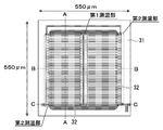
- FIG. 2 is a top view of the heat flux sensor.
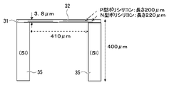
- 3 is a cross-sectional view of the heat flux sensor taken along line BB in FIG. 4 is a cross-sectional view of the heat flux sensor taken along line AA in FIG.
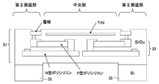
- FIG. 5 is a schematic cross-sectional view of the main part along the line CC in FIG. 2 of the heat flux sensor.
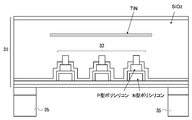
- 6 is a schematic cross-sectional view of the heat flux sensor taken along line AA in FIG.
- FIG. 7 is an explanatory diagram of the principle of measuring the internal temperature by the internal temperature sensor.
- FIG. 8 is a flowchart of the internal temperature calculation process.
- FIG. 8 is a flowchart of the internal temperature calculation process.
- FIG. 9 is an explanatory diagram of values used to calculate the values of the coefficients k and a during the internal temperature calculation process.
- FIG. 10 is a schematic configuration diagram of an internal temperature sensor according to the second embodiment of the present invention.
- FIG. 11 is a schematic configuration diagram of an internal temperature sensor according to the third embodiment of the present invention.
- FIG. 12 is a top view of the heat flux sensor provided in the internal temperature sensor according to the third embodiment.
- FIG. 13A is an explanatory diagram of a main board that can be employed in the internal temperature sensor according to each embodiment.
- FIG. 13B is an explanatory diagram of a main board that can be employed in the internal temperature sensor according to each embodiment.
- FIG. 13A is an explanatory diagram of a main board that can be employed in the internal temperature sensor according to each embodiment.
- FIG. 13B is an explanatory diagram of a main board that can be employed in the internal temperature sensor according to each embodiment.
- FIG. 14 is an explanatory diagram of a configuration of a heat flux sensor that can be employed in the internal temperature sensor according to each embodiment.
- FIG. 15 is an explanatory diagram of members that can be used as a top plate or the like.
- FIG. 16 is an explanatory diagram of the principle of measuring the deep body temperature using an existing non-heating type deep body thermometer.
- FIG. 1 shows a schematic configuration of an internal temperature sensor 20 according to the first embodiment of the present invention.
- the internal temperature sensor 20 includes a main board 21, a sensor board 22 disposed on the main board 21, an arithmetic circuit 23, and a terminal 24. Further, the internal temperature sensor 20 includes a heat flux sensor 30 and an ASIC (Application Specific Integrated Circuit) 40 disposed on the sensor substrate 22, and a housing 50 that covers the heat flux sensor 30 and the ASIC 40.
- ASIC Application Specific Integrated Circuit
- the internal temperature sensor 20 is a sensor that can measure the internal temperature of the measurement object by bringing the lower surface of the main substrate 21 into contact with the surface of the measurement object (human body or device).
- the lower surface and the upper surface of a certain member are the lower surface and the upper surface in FIG.
- the main board 21 is a board on which wiring between the ASIC 40, the arithmetic circuit 23, and the terminal 24 is formed.
- the main substrate 21 is preferably one having good thermal conductivity (one having a low thermal resistance). Even if the thermal conductivity is good, if the thickness of the main substrate 21 is large, it takes time to measure the internal temperature. Therefore, it is desirable that the thickness of the main substrate 21 be as thin as possible.
- the terminal 24 on the main board 21 is a terminal to which a power line and a signal line from the measuring device for the internal temperature sensor 20 are connected.
- the measuring device for the internal temperature sensor 20 acquires the measurement result of the internal temperature from the internal temperature sensor 20 by communicating with the internal temperature sensor 20 via a signal line, and displays the acquired measurement result. It is a device having a function of recording and a function of supplying power to the internal temperature sensor 20 through a power line.
- the heat flux sensor 30 is a small temperature difference sensor manufactured by a so-called MEMS (Micro Electro Mechanical Systems) process (a semiconductor process including a high aspect ratio etching process). Although shown in a simplified form in FIG. 1, the heat flux sensor 30 has a configuration as shown in FIGS. Of these figures, FIG. 2 is a top view of an example of the heat flux sensor 30, and FIGS. 3 and 4 respectively show the BB line in FIG. 2 of the heat flux sensor 30 shown in FIG. 2. FIG. 3 is a cross-sectional view taken along line AA.
- MEMS Micro Electro Mechanical Systems
- the heat flux sensor 30 includes, for example, a thin film portion 31 (see FIG. 2) of 550 ⁇ m square and silicon extending downward from the peripheral portion of the lower surface of the thin film portion 31 and is approximately 400 ⁇ m long (396.2 ⁇ m long)
- the support part 35 (refer FIG.3, 4) is provided.
- a thermopile 32 in which a plurality of thermocouples composed of P-type polysilicon and N-type polysilicon are connected in series is formed in the thin film portion 31 provided in the heat flux sensor 30.
- the thermopile 32 in the thin film portion 31 is formed on the first temperature measuring portion that is the central portion of the thin film portion 31 in the horizontal direction in FIG. 2 and on the support portion 35 of the thin film portion 31.
- a square-shaped support portion 35 made of silicon having a high thermal conductivity exists below the peripheral portion of the thin film portion 31. Therefore, the two second temperature measuring parts shown in FIG. 2 can be handled as parts having the same temperature.
- the thin film portion 31 of the heat flux sensor 30 is formed by using a material having a relatively low thermal conductivity in a portion other than the thermopile 32 (P-type polysilicon, N-type polysilicon, wiring connecting each portion, etc.). . That is, the thin film portion 31 is formed so that the overall thermal conductivity is relatively small.
- the heat flux sensor 30 is manufactured to have a structure as shown in FIGS. 5 and 6, for example.
- 5 is a schematic cross-sectional view of the main part of the heat flux sensor 30 taken along line CC in FIG. 2
- FIG. 6 is a schematic cross-sectional view of the heat flux sensor 30 taken along line AA in FIG. is there.
- the thin film portion 31 of the heat flux sensor 30 is formed using SiO 2 having poor thermal conductivity in portions other than the thermopile 32.
- the TiN layer shown on the thermopile 32 is a lower portion of the central portion of the thin film portion 31 (a portion other than the second temperature measuring portion, a portion having a space below). It is provided as an infrared absorption / radiation layer for encouraging heat to be released upward from various places.
- This infrared absorption / radiation layer is not an essential component of the heat flux sensor 30.
- the temperature difference ⁇ T detected by the heat flux sensor 30 is usually small. As a result, the measurement accuracy of the internal temperature is slightly lowered (details will be described later). Therefore, it is preferable to provide an infrared absorption / radiation layer in the thin film portion 31 of the heat flux sensor 30.
- the ASIC 40 is an integrated circuit in which the temperature sensor 41 is built.
- the ASIC 40 has a function of amplifying the output of the heat flux sensor 30 and the output of the temperature sensor 41, and a function of converting each amplified output into digital data.
- the ASIC 40 of the heat flux sensor 30 is a circuit including a PTAT (Proportional To Absolute Absolute) voltage source (that is, a voltage source that functions as a thermometer) that outputs a voltage proportional to the absolute temperature. That is, the ASIC 40 is a circuit in which the components of the PTAT voltage source function as the temperature sensor 41.
- the ASIC 40 is also a circuit that amplifies the output of each sensor by a chopper amplifier.
- the sensor substrate 22 on which the heat flux sensor 30 and the ASIC 40 are disposed is a highly thermally conductive member provided so that the temperature sensor 41 can measure the temperature of the lower surface of the support portion 35 of the heat flux sensor 30. It is.
- the sensor substrate 22 is a member provided to match the temperature of the portion where the support portion 35 of the heat flux sensor 30 is fixed with the temperature of the portion where the temperature is measured by the temperature sensor 41. It has become. Therefore, when a member having sufficiently large thermal conductivity is used as the main substrate 21, the heat flux sensor 30 and the ASIC 40 can be directly mounted on the main substrate 21 without providing the sensor substrate 22.
- the arithmetic circuit 23 is a circuit that calculates and outputs the internal temperature of the measurement object based on the output of the heat flux sensor and the output of the temperature sensor converted into digital data by the ASIC 40. As will be described in detail later, as the arithmetic circuit 23, a circuit that outputs (sends) the calculated internal temperature from the terminal 24 or a circuit that outputs (stores) the calculated internal temperature to an internal memory is usually used.
- the housing 50 mainly stabilizes the output of both sensors by fixing the air around the heat flux sensor 30 and the temperature sensor 41 (ASIC 40), and allows infrared rays to enter the heat flux sensor 30 from above. This is a case of the heat flux sensor 30 and the temperature sensor 41 provided for the purpose of preventing.
- the housing 50 includes a cylindrical side wall 51 that surrounds the heat flux sensor 30 and the temperature sensor 41 (ASIC 40), and a heat insulating material 52 at the opening of the side wall 51. And the infrared ray absorber 54 disposed so as to cover the inner surface of the side wall 51.
- the side wall 51 a member having a diameter of about 1 cm or less is usually used.
- the side wall 51 of the housing 50 is preferably fixed to the sensor substrate 22 by using a heat conductive adhesive (for example, silver paste) or the like.
- the constituent material of the side wall 51 and the top plate 53 of the housing 50 may be any material that can prevent the air from entering and leaving the inside and outside of the housing 50 and the inflow of infrared rays into the housing 50.
- the outputs of the heat flux sensor 30 and the temperature sensor 41 can be changed by electromagnetic waves. Therefore, it is preferable that the constituent material of the side wall 51 and the top plate 53 is a material that can prevent inflow of electromagnetic waves from the outside, that is, a metal or a nonmetal having conductivity.
- the upper surface of the top plate 53 has a higher infrared reflectance, so that the temperature in the housing 50 is stabilized.
- the top plate 53 of the housing 50 a member made of a material with high infrared reflectance (for example, aluminum) or a member made of a material with relatively low infrared reflectance (for example, SUS or non-metal) is used. It is preferable to use a member in which a thin plate made of a material having high infrared reflectance is attached to the upper surface. Moreover, it is preferable that the lower surface exposed to the inside of the top plate 53 is an infrared absorber.
- the heat insulating material 52 of the housing 50 may be a member having a heat insulating property. Therefore, as the heat insulating material 52, a material (such as urethane foam) generally used as a heat insulating material can be used.
- the infrared absorber 54 of the housing 50 may be a member that easily absorbs infrared rays. As the infrared absorber 54, for example, a black resin can be used.
- the thermal resistance values of the substrates 21 and 22 can be regarded as “0” (which is sufficiently smaller than the thermal resistance value of the non-heating portion of the measurement object).
- a heat circuit in which heat (solid line / dashed arrow) moves between the respective parts in the form schematically shown in FIG. Will be formed.
- This thermal circuit can be represented as the electric circuit shown in FIG. 7B, but the value of Ih ′ in the electric circuit is R4 >> R2 (the value of R4 is larger than the value of R2). The value of Ih is almost the same.
- R4 >> R2 is materialized about the internal temperature sensor 20 (heat flux sensor 30).
- the internal temperature sensor 20 brought into contact with the measurement object when the internal temperature sensor 20 brought into contact with the measurement object is in a thermal equilibrium state, it flows in the thin film portion 31 of the heat flux sensor 30 from the second temperature measuring portion side to the first temperature measuring portion side within a unit time.
- the amount of heat Q1 and the amount of heat Q2 flowing into the support portion 35 of the heat flux sensor 30 from the non-heating element (measurement object) side within a unit time substantially coincide with each other.
- Q1 and Q2 can be calculated by the following equations (3) and (4), respectively.
- Q1 (Th ⁇ Tl) / R2 (3)
- Q2 (Tb ⁇ Tr) / Rx (4)
- Th and Tl are the temperature of the second temperature measuring unit and the temperature of the first temperature measuring unit, respectively.
- Tr is the temperature of the lower end of the support unit 35 measured by the temperature sensor 41 (surface of the non-heating element) Temperature).
- the “Rx / R2” value in the equation (6) is a value that uniquely determines an appropriate value depending on the structure of the internal temperature sensor 20 (size of each part, constituent material of each part, etc.) and the measurement object. . Therefore, the internal temperature Tb can be calculated by the above equation (6) from the temperature difference ⁇ T and the temperature Tr measured by the heat flux sensor 30 and the temperature sensor 41, respectively.
- Rx in the equation (6) is expressed as “Rx + thermal resistance value of the substrates 21 and 22” (hereinafter, Rx ′).
- the “Rx ′ / R2” value in the equation (7) is also a value for which an appropriate value is uniquely determined by the structure of the internal temperature sensor 20 and the measurement object. Therefore, even when the thermal resistance values of the substrates 21 and 22 cannot be regarded as “0”, the internal temperature Tb can be calculated from the temperature difference ⁇ T and the temperature Tr.
- Such a k value is obtained, for example, by measuring ⁇ T and Tr several times using the internal temperature sensor 20 for the measurement object (or the object imitating the measurement object) whose internal temperature is changed, and the result Can be obtained by the least squares method or the like. Therefore, the internal temperature sensor 20 can determine the calculation formula (equation (8)) for the internal temperature Tb without considering whether or not the thermal resistance values of the substrates 21 and 22 can be regarded as “0”. It will be a thing.
- TiN TiN
- FIGS. 5 and 6 a supplementary explanation will be given for the TiN layer ("TiN" in FIGS. 5 and 6) formed in the thin film portion 31.
- the internal temperature sensor 20 has improved sensitivity when the ⁇ T value measured by the thermal flow rate sensor 30 is increased. is there.
- the ⁇ T value increases and the upward from the first temperature measuring unit increases as the amount of heat released upward from the first temperature measuring unit increases.
- the TiN layer is provided in the first temperature measuring part of the thin film part 31 and the vicinity thereof.
- prompting the amount of heat radiation upward from the first temperature measuring unit can also be realized by forming minute irregularities on the upper surface of the first temperature measuring unit. Therefore, instead of providing an infrared absorption / radiation layer, even if minute irregularities are formed on the upper surface of the first temperature measurement unit, an infrared absorption / radiation layer is provided in the first temperature measurement unit and the first temperature measurement Fine irregularities may be formed on the upper surface of the portion.
- the arithmetic circuit 23 used (mounted) for the internal temperature sensor 20 may be any circuit that can calculate the internal temperature Tb from the temperature difference ⁇ T and the temperature Tr.
- a circuit for calculating the internal temperature Tb from the temperature difference ⁇ T and the temperature Tr using the preset k value by the equation (8) can be used. Further, as the arithmetic circuit 23, a circuit in which such a circuit is provided with a function of accepting a change of the k value (when a command instructing the change of the k value is input via the terminal 24, the k value is changed according to the command. Circuit) can also be used.
- a circuit that starts the internal temperature measurement process of the procedure shown in FIG. 8 when a predetermined condition is satisfied can be used as the arithmetic circuit 23.
- a predetermined condition a condition such as “a predetermined command is input to the terminal 24” or “a temperature Tr (temperature measured by the temperature sensor 41) starts to rise” (that is, the lower surface of the substrate 21). For example, a contact with the object to be measured).
- the arithmetic circuit 23 that has started this internal temperature measurement process first performs a process (step S101) of continuously (periodically) measuring the Tr value and the ⁇ T value.
- a process that ends before the internal temperature sensor 20 reaches thermal equilibrium for example, a process that ends when the rate of change of the ⁇ T value becomes a predetermined value or less
- the processing actually performed in step S101 includes data representing the Tr value (temperature measurement result by the temperature sensor 41) and ⁇ T value (by the thermal flow rate sensor 30). This is a process of continuously collecting data representing the temperature difference measurement result) from the ASIC 40.
- the arithmetic circuit 23 that has finished the process of step S101, based on the measurement result of Tr value and ⁇ T value (data group collected from the ASIC 40), shows the following “calculation formula of the internal temperature Tb that holds even before reaching thermal equilibrium”.
- the process of calculating the values of the coefficients k and a is performed (step S102).
- Tb Tr + k ⁇ T + a (dTr / dt) (9)
- step S102 the arithmetic circuit 23 performs the following processing.
- the arithmetic circuit 23 selects three measurement results (a pair of Tr value and ⁇ T value) measured at different times t1, t2, and t3 (t1 ⁇ t2 ⁇ t3) from the measurement results collected during the process of step S101. ) Is selected.
- the arithmetic circuit 23 calculates the dTr / dt value at time t1 (hereinafter referred to as dTr 1 / dt), the dTr / dt value at time t2 (hereinafter referred to as dTr 2 / dt), and dTr / at time t3.
- a dt value (hereinafter referred to as dTr 3 / dt) is calculated.
- the method for selecting Tr 1 to Tr 3 and ⁇ T 1 to ⁇ T 3 is not particularly limited. However, as illustrated in FIG. 9, it is preferable to select Tr 1 to Tr 3 and ⁇ T 1 to ⁇ T 3 so that there are no 2Tr values or 2 ⁇ T values that are close to each other. This is because if the Tr 1 to Tr 3 and ⁇ T 1 to ⁇ T 3 are selected in this way, the k value and the a value can be calculated with high accuracy.
- the arithmetic circuit 23 calculates the k value and the a value by solving the following simultaneous equations. Process.
- Tb Tr 1 + k ⁇ T 1 + a (dTr 1 / dt)
- Tb Tr 2 + k ⁇ T 2 + a (dTr 2 / dt)
- Tb Tr 3 + k ⁇ T 3 + a (dTr 3 / dt)
- the arithmetic circuit 23 adds Tr 1 to Tr 3 , ⁇ T 1 to ⁇ T 3, and dTr 1 / dt to the a value calculation formula and the k value calculation formula obtained from the above three formulas, respectively.
- Tr 1 to Tr 3 ⁇ T 1 to ⁇ T 3
- dTr 1 / dt a process of calculating the k value and the a value is performed.
- the arithmetic circuit 23 that has calculated the k value and the a value by the above procedure ends the process of step S102. Then, the arithmetic circuit 23 measures the Tr value and ⁇ T value (Step S103), and the Tr value measured in the calculation formula (Equation (9)) of the internal temperature Tb in which the calculated values are set as the k value and the a value. And the process of calculating and outputting the internal temperature Tb by substituting the ⁇ T value (step S104).
- step S104 is a process of outputting (transmitting) the calculated internal temperature Tb from the terminal 24, the calculated internal temperature Tb is connected to the internal temperature sensor 20 via the measuring device (terminal 24).
- the processing may be a process of outputting (storing) to a memory in the arithmetic circuit 23 accessible by the device.
- the internal temperature calculation processing of the procedure shown in FIG. 7 is performed using the internal temperature Tb calculation formula (formula (9)) that is established even before reaching the thermal equilibrium.
- Tb the internal temperature
- the values of the coefficients a and k of the calculation formula are automatically calculated. Therefore, if the arithmetic circuit 23 capable of executing the internal temperature calculation process is used, the internal temperature sensor 20 capable of measuring the accurate internal temperature Tb before reaching the thermal equilibrium state can be realized regardless of the measurement object. Become.
- the heat flux sensor 30 included in the internal temperature sensor 20 according to the present embodiment is small in size, and thus has a small heat capacity (that is, a temperature at which each part is stabilized in a short time). ing. Moreover, since the heat flux sensor 30 measures the temperature difference by the thermopile 32, the measurement accuracy of the temperature difference is high.
- thermopile 32 Although it is difficult to manufacture a vertical thermopile, a horizontal thermopile such as the thermopile 32 can be easily manufactured. And even if it uses (DELTA) T measured by the heat flux sensor 30 provided with the horizontal type thermopile 32, as above-mentioned, the internal temperature Tb of a measuring object can be measured (calculated).
- DELTA DELTA
- the internal temperature sensor 20 according to this embodiment is used, the internal temperature of the measurement object can be accurately measured with good responsiveness. It should be noted that the internal temperature sensor 20 equipped with the heat flux sensor 30 of the size shown in FIGS. 2 to 4 has been confirmed from various experimental results that the measurement result is stable after waiting at least 3 minutes.
- FIG. 10 shows a schematic configuration of an internal temperature sensor 20b according to the second embodiment of the present invention.
- the internal temperature sensor 20b has many parts in common with the internal temperature sensor 20 according to the first embodiment. Therefore, hereinafter, the configuration and function of the internal temperature sensor 20b will be described with a focus on the differences from the internal temperature sensor 20.
- the internal temperature sensor 20 b is disposed on the main substrate 21, the sensor substrate 22 disposed on the main substrate 21, the arithmetic circuit 23 and the terminal 24, and the sensor substrate 22.
- the heat flux sensor 30 and the ASIC 40 are provided. These members / circuits are the same as the members / circuits having the same name / symbol provided in the internal temperature sensor 20.
- the internal temperature sensor 20b also includes a housing 50b for covering the heat flux sensor 30 and the ASIC 40.
- the housing 50b of the internal temperature sensor 20b is obtained by replacing the top plate 53 of the housing 50 (see FIG. 1) with a heat sink 55 as shown.
- a second temperature measuring unit heat retaining structure 36 is disposed on the heat flux sensor 30 of the internal temperature sensor 20b.
- the second temperature measuring portion heat retaining structure 36 is a member having a shape in which a portion facing the first temperature measuring portion and a portion other than the peripheral portion are recessed. ing.
- the second temperature measuring section heat retaining structure 36 of the internal temperature sensor 20b and the heat sink 55 are connected by a high thermal conductive member 37 made of a material having good thermal conductivity (for example, aluminum).
- the internal temperature sensor 20b is configured so that the temperature of the first temperature measuring unit matches the outside air temperature and the second temperature measuring unit is kept warm (second temperature measuring unit).
- the internal temperature sensor 20 is modified / improved so that the amount of heat released upward from the air does not become excessively large.
- the internal temperature of the measurement object can be measured with higher accuracy than when the internal temperature sensor 20 is used.
- a heat flux sensor 30c and an ASIC 40c are disposed on the sensor substrate 22 of the internal temperature sensor 20c according to the present embodiment.
- the ASIC 40c is an integrated circuit corresponding to the ASIC 40 obtained by removing the temperature sensor 41 (a diode and a resistor functioning as the temperature sensor 41).
- the heat flux sensor 30c is a sensor having a thin film portion 31c in which a temperature sensor 41 (a diode or the like removed from the ASIC 40) is formed, as schematically shown in FIG.
- the heat flux sensor 30c is an improvement of the heat flux sensor 30 so that the temperature of the second temperature measuring unit can be directly measured.
- the internal temperature Tb can be calculated by the above-described equation (8) or (9). I can do it.
- the internal temperature sensor 20c includes an arithmetic circuit that calculates the internal temperature Tb from the temperature difference ⁇ T and the temperature Tr using the preset k value using the equation (8). 23.
- An arithmetic circuit 23 or the like that can execute the internal temperature measurement process (FIG. 8) can be mounted.
- the housing 50c included in the internal temperature sensor 20c is obtained by replacing the heat sink 55 of the housing 50b with a heat sink 56 having a relatively large area. Yes. Further, the internal temperature sensor 20c includes a first temperature measuring portion of the thin film portion 31 of the heat flux sensor 30c by using a highly heat conductive soft material 58 (for example, heat conductive silicone rubber or silicone grease). (See FIG. 2).
- a highly heat conductive soft material 58 for example, heat conductive silicone rubber or silicone grease.
- the heat flux sensor 30c included in the internal temperature sensor 20c according to the present embodiment also has a small heat capacity, so that the temperature of each part is stabilized in a short time, and the temperature difference is controlled by the thermopile 32. Because of the measurement, the measurement accuracy of the temperature difference is high.
- the internal temperature of the measurement object can be accurately measured with good responsiveness.
- the internal temperature sensor (20, 20b, 20c) according to each of the above embodiments can be variously modified.
- the internal temperature sensor 20 c (FIG. 11) can be transformed into a sensor provided with a heat sink 55 instead of the heat radiating plate 56.
- the internal temperature sensors 20 and 20b can be modified to a sensor including the heat flux sensor 30c and the ASIC 40c instead of the heat flux sensor 30 and the ASIC 40.
- a thin main board 21 on which the heat flux sensor 30 and the ASIC 40 are mounted can be adopted. Further, in order to lower the average thermal resistance of the main board 21, as shown schematically in FIG. 13B, a plurality of through holes are formed in the main board 21, and a metal 29 is filled in each formed through hole. You can also keep it.
- an infrared reflecting layer such as an Al layer can be formed in the thin film portion, on the first and second temperature measuring portions with the reflecting surface facing upward.
- the infrared reflective layer is preferably formed of a material having a low thermal conductivity. Further, when the infrared reflective layer is formed of a material having a relatively high thermal conductivity, as schematically shown in FIG.
- the second temperature measuring unit side and the central part (first temperature measuring unit) side It is desirable to form the infrared reflecting layer in the form divided into Further, if the infrared reflecting film of the second temperature measuring unit is also provided with a reflecting surface on the lower side, high accuracy can be expected due to the heat retaining effect.
- the infrared rays irradiated from the outside toward the upper surface of the thin film portion 31 can be reflected to prevent the thin film portion 31 from being heated by the infrared rays. Therefore, it can be said that this structure is a particularly effective structure when the internal temperature sensor 20 is realized as a sensor that does not include the housing 50.
- the internal temperature sensor according to each embodiment is transformed into a sensor that does not include the arithmetic circuit 23 (a sensor that outputs the output of the ASICs 40 and 40c as it is), or a sensor that outputs the output of the heat flux sensors 30 and 30c and the temperature sensor 41 as they are. You can also However, if the outputs of the heat flux sensors 30, 30c and the temperature sensor 41 are output as they are, they are easily affected by noise. For this reason, the internal temperature sensor is preferably equipped with an amplifier that amplifies the output of each sensor.
- the arithmetic circuit 23 can also be transformed into a circuit that calculates the internal temperature of the measurement object by solving the heat conduction equation based on the time-series temperature difference and temperature measurement results by each sensor.
- each part of the internal temperature sensor 20 can be changed as appropriate.
- the heat insulating material 52 and the top plate 53 are relatively thin.
- the thickness of the heat insulating material 52 and the top plate 53 is not particularly limited, for example, as shown in FIG. 15, thick foamed urethane is used as the heat insulating material 52, and the infrared reflecting plate is formed on the thick conductive foam as the top plate 53. It is also possible to use an aluminum foil attached.
Landscapes
- Physics & Mathematics (AREA)
- General Physics & Mathematics (AREA)
- Engineering & Computer Science (AREA)
- Chemical & Material Sciences (AREA)
- Combustion & Propulsion (AREA)
- Computer Hardware Design (AREA)
- Microelectronics & Electronic Packaging (AREA)
- Radiation Pyrometers (AREA)
- Micromachines (AREA)
- Measuring Volume Flow (AREA)
Abstract
測定対象物の内部温度を、精度及び応答性が良い形で測定できる内部温度センサ。内部温度センサ20は、測定対象物の内部温度の測定時に、その一方の面を測定対象物の被測定面に接触させる基材21及び22と、基材の他方の面上に設けられた、MEMSプロセスにより製造された、第1測温部及び第2測温部を有し、第1測温部と第2測温部との間の温度差を検出するサーモパイル32が形成されている薄膜部を含み、薄膜部が、基材を介して流入する測定対象物からの熱を第2測温部に伝導する熱伝導性部材により第1測温部と基材との間に空間が存在し、且つ、薄膜部が基材に対して平行となるように支持された熱流束センサ30と、基材の熱伝導性部材と接触している部分の温度を測定するための温度センサ41とを備える。
Description
本発明は、測定対象物の内部温度を測定するための内部温度センサに関する。
深部体温を測定する装置として、非加熱型の簡易型深部体温計等と称されている装置(以下、非加熱型深部体温計と表記する;特許文献1~3参照)が存在している。
以下、図16を用いて、非加熱型深部体温計による深部体温の基本的な測定(算出)原理を説明する。
非加熱型深部体温計による深部体温の測定時には、図16(a)に示してあるように、比較的に面積の広い断熱材の上下面にそれぞれ温度センサを取り付けた熱流束センサが、体表面に密着される。
ここで、深部体温をTb、外気に接触している側の断熱材表面の温度をTa、体表面に接触している断熱材表面の温度をTt、非発熱体である皮下組織の熱抵抗値をR1、断熱材の熱抵抗値をR2と表記すると、図16(a)に示してある熱回路は、図16(b)に電気回路として表せることになる。
また、体表面に密着させた熱流束センサの各部の温度が安定すると、非発熱体を単位時間に通過する熱量と断熱材を単位時間に通過する熱量とが等しくなるため、以下の(1)式が成立する。
(Tb-Tt)/R1=(Tt-Ta)/R2 …(1)
(Tb-Tt)/R1=(Tt-Ta)/R2 …(1)
従って、以下の(2)式により、深部体温Tbを算出できることになる。
Tb=Tt+(Tt-Ta)・R1/R2 …(2)
Tb=Tt+(Tt-Ta)・R1/R2 …(2)
非加熱型深部体温計は、上記原理で深部体温Tbを算出するものとなっている。
非加熱型深部体温計は、熱流補償法を応用した深部体温測定装置よりも小型、低価格、低消費電流なものとなる。ただし、既存の非加熱型深部体温計は、温度差を断熱材をはさんだ2つの温度センサを用いて測定するものとなっており、温度センサの精度から、断熱材の断熱性がある程度大きく無ければ、2温度センサにより或る程度の精度で測定できるレベルの温度差を作りだすことが出来ない。そのため、非加熱型深部体温計には、熱容量が大きな断熱材が使用されており、その結果として、非加熱型深部体温計により深部体温の安定した測定結果を得るためには、短くても5分程度の時間を要している。また、断熱性の大きな断熱材が熱流を乱すため、非加熱型深部体温計は、測定精度がさほど高くないものとなっている。
本発明は、上記現状に鑑みてなされたものであり、測定対象物の内部温度を、精度及び応答性がより良い形で測定できる内部温度センサを提供することを課題とする。
上記課題を解決するために、本発明の内部温度センサは、
測定対象物の内部温度の測定時に、その一方の面を測定対象物の表面に接触させる基材と、
基材の他方の面上に設けられた、MEMS(Micro Electro Mechanical Systems)プロセスにより製造された熱流束センサであって、第1測温部及び第2測温部を有し、第1測温部と第2測温部との間の温度差を検出するサーモパイルが形成されている薄膜部を含み、基材を介して流入する測定対象物からの熱を第2測温部に伝導する熱伝導性部材により、第1測温部と基材との間に、熱伝導性部材より熱伝導性が悪い空間が存在し、且つ、基材に対して平行となるように、薄膜部が支持された熱流束センサと、
基材の熱伝導性部材と接触している部分の温度又は薄膜部の第2測温部の温度を測定するための温度センサと、
を備える。
測定対象物の内部温度の測定時に、その一方の面を測定対象物の表面に接触させる基材と、
基材の他方の面上に設けられた、MEMS(Micro Electro Mechanical Systems)プロセスにより製造された熱流束センサであって、第1測温部及び第2測温部を有し、第1測温部と第2測温部との間の温度差を検出するサーモパイルが形成されている薄膜部を含み、基材を介して流入する測定対象物からの熱を第2測温部に伝導する熱伝導性部材により、第1測温部と基材との間に、熱伝導性部材より熱伝導性が悪い空間が存在し、且つ、基材に対して平行となるように、薄膜部が支持された熱流束センサと、
基材の熱伝導性部材と接触している部分の温度又は薄膜部の第2測温部の温度を測定するための温度センサと、
を備える。
すなわち、本発明の内部温度センサは、MEMSプロセスにより製造された熱流束センサ(つまり、小型であるが故に熱容量が小さい熱流束センサ)を備える。また、本発明の内部温度センサが備える熱流束センサは、サーモパイルにより温度差を測定するものであるが故に、温度差の測定精度が高いものとなっている。従って、本発明の内部温度センサによれば、測定対象物の深部温度を、従来のセンサを用いた場合よりも、精度及び応答性が良い形で測定できることになる。
尚、本発明に係る熱流束センサの第1測温部と基材との間の “熱伝導性部材より熱伝導性が悪い空間”は、空気等の気体がその内部に存在する空間であっても、その内部が真空の空間であっても、その内部に、熱伝導性が悪い非気体の樹脂などが充填される空間であっても良い。
本発明の内部温度センサを実現するに際しては、熱流束センサの薄膜部として、第1測温部からの放熱を促すための放熱促進構造を含むものを採用しておくことが好ましい。何故ならば、放熱促進構造を含む薄膜部を採用しておけば、より高精度に測定対象物の深部温度を測定できることになるからである。尚、第1測温部からの放熱を促すための放熱促進構造を含む薄膜部には、例えば、第1測温部の上面(基材と対向しない側の面)側に、基板側の部分から放射される赤外線を吸収して上方(基材と反対側の方向)に放出する赤外線吸収・放射層が形成されている薄膜部がある。また、第1測温部の上面が平面(鏡面)だと、下方からの赤外線が第1測温部の上面で反射されてしまうので、第1測温部の上面に凹凸が形成されている薄膜部も、第1測温部からの放熱を促すための放熱促進構造を含む薄膜部として機能することになる。
また、熱流束センサ及び温度センサの周囲の空気を固定しておいた方が、深部温度の測定結果を安定させることが出来る。従って、本発明の内部温度センサを実現する際には、熱流束センサと温度センサとを覆うハウジングを付加しておくことが好ましい。
また、熱流束センサの薄膜部に、薄膜部の基材と対向しない側の面に向けて照射された赤外線を反射して当該赤外線による前記薄膜部の加熱を防止する赤外線反射構造を含めておけば、ハウジングを設けなくても、深部温度の測定結果を安定させることが出来る。
さらに、ハウジングの内面に赤外線吸収体を配置しておけば、ハウジング内の温度をより安定化することが出来る。また、ハウジングとして、赤外線及び電磁波を反射する外面を有するものを採用しておけば、ハウジング内の温度をさらに安定化することが出来ると共に、電磁波が内部温度の測定結果に悪影響を与えないようにすることが出来ることになる。
内部温度センサのハウジングとしては、熱流束センサ及び温度センサを囲む側壁部と、側壁部の開口部側の端面に設けられた断熱材と、断熱材を介して側壁部に対して取り付けられた、側壁部の開口部を覆う天板とを含むものを採用しておくことが出来る。また、当該ハウジングの天板を、表面積を大きくして放熱性を向上させたヒートシンク又は放熱板としておくことが出来る。また、内部温度センサに、薄膜部の第1測温部からの熱を天板に伝達するための部材を付加しておくことも出来る。
本発明の内部温度センサは、熱流束センサの出力と温度センサの出力とをそのまま出力するセンサとして実現することも出来るものである。ただし、各センサが出力する信号は低レベルの信号なので、各センサの出力をそのまま出力すると、ノイズの影響で正確な内部温度を算出できない恐れがある。そのため、内部温度センサには、各センサの出力を増幅する増幅器を搭載しておくことが好ましい。さらに、そのような増幅器と共に、当該増幅器により増幅された熱流束センサの出力と温度センサの出力とに基づき、測定対象物の内部温度を算出する演算部を付加しておけば、外部装置で測定対象物の内部温度を算出しなくても良い内部温度センサを実現できることになる。
本発明に係る内部温度センサによれば、測定対象物の内部温度を、従来のセンサを用いた場合よりも精度及び応答性が良い形で測定することが出来る。
《第1実施形態》
図1に、本発明の第1実施形態に係る内部温度センサ20の概略構成を示す。
図1に、本発明の第1実施形態に係る内部温度センサ20の概略構成を示す。
図示してあるように、本実施形態に係る内部温度センサ20は、主基板21と、主基板21上に配設されたセンサ基板22、演算回路23及びターミナル24とを、備える。また、内部温度センサ20は、センサ基板22上に配設された熱流束センサ30及びASIC(Application Specific Integrated Circuit)40と、熱流束センサ30及びASIC40を覆うハウジング50とを、備える。
この内部温度センサ20は、主基板21の下面を測定対象物(人体や装置)の表面に接触させることにより、当該測定対象物の内部温度を測定することが出来るセンサである。尚、上記説明及び以下の説明において、或る部材の下面、上面とは、それぞれ、当該部材の図1における下側、上側の面のことである。
主基板21は、ASIC40、演算回路23、ターミナル24間の配線が形成されている基板である。この主基板21は、熱伝導性が良いもの(熱抵抗が小さなもの)であることが好ましい。また、熱伝導性が良いものであっても、主基板21の厚さが厚いと、内部温度の測定に時間がかかるようになる。従って、主基板21の厚さは、極力薄いことが望まれる。
主基板21上のターミナル24は、内部温度センサ20用の計測装置からの電源線及び信号線が接続されるターミナルである。ここで、内部温度センサ20用の計測装置とは、信号線を介して内部温度センサ20と通信を行うことにより内部温度センサ20から内部温度の測定結果を取得し、取得した測定結果の表示や記録を行う機能や、電源線を介して内部温度センサ20に電力を供給する機能を有する装置のことである。
熱流束センサ30は、いわゆるMEMS(Micro Electro Mechanical Systems)プロセス(高アスペクト比エッチングプロセスを含む半導体プロセス)により製造された小型の温度差センサである。図1には、簡略化した形で示してあるが、この熱流束センサ30は、図2~図4に示したような構成を有している。尚、これらの図のうち、図2は、熱流束センサ30の一例の上面図であり、図3、図4は、それぞれ、図2に示した熱流束センサ30の図2におけるB-B線、A-A線に沿った断面図である。
すなわち、熱流束センサ30は、例えば、550μm角の薄膜部31(図2参照)と、薄膜部31の下面の周部から下方に延びた、シリコンからなる,およそ400μm長(396.2μm長)の支持部35(図3,4参照)とを備える。熱流束センサ30が備える薄膜部31の内部には、P型ポリシリコンとN型ポリシリコンとで構成された複数の熱電対を直列に接続したサーモパイル32が形成されている。図2及び図3から明らかなように、薄膜部31内のサーモパイル32は、薄膜部31の図2における左右方向の中心部分である第1測温部と、薄膜部31の支持部35上の部分である第2測温部との間の温度差を測定できるように形成されている。尚、薄膜部31の周部の下方には、熱伝導率が大きいシリコンからなる,ロの字状の支持部35が存在している。従って、図2に示してある2つの第2測温部を、温度が等しい部分として取り扱うことが出来る。
熱流束センサ30の薄膜部31は、サーモパイル32(P型ポリシリコン、N型ポリシリコン、各部を接続する配線等)以外の部分に熱伝導率が比較的に悪い材料を用いることにより形成される。すなわち、薄膜部31は、全体的な熱伝導率が比較的に小さくなるように形成される。
具体的には、熱流束センサ30は、例えば、図5及び図6に示したような構造を有するように製造される。図5は、熱流束センサ30の図2におけるC-C線に沿った要部概略断面図であり、図6は、熱流束センサ30の図2におけるA-A線に沿った概略断面図である。
これらの図から明らかなように、熱流束センサ30の薄膜部31は、サーモパイル32以外の部分に熱伝導率が悪いSiO2を用いて形成されるものとなっている。
尚、図5及び図6において、サーモパイル32上に示されているTiN層は、薄膜部31の中央部(第2測温部以外の部分、下方が空間となっている部分)の下方部分の各所から上方向に熱が放出されることを促すための赤外線吸収・放射層として設けられているものである。この赤外線吸収・放射層は、熱流束センサ30の必須構成要素ではない。ただし、赤外線吸収・放射層を設けない場合、熱流束センサ30によって検出される温度差ΔTが通常小さくなる。そして、その結果として、内部温度の測定精度が若干低下する(詳細は後述)ので、熱流束センサ30の薄膜部31には、赤外線吸収・放射層を設けておくことが好ましい。
図1に戻って、熱流束センサ30の説明を続ける。
ASIC40は、温度センサ41を内蔵した集積回路である。ASIC40は、熱流束センサ30の出力及び温度センサ41の出力を増幅する機能と、増幅後の各出力をデジタルデータ化する機能とを有している。尚、本実施形態に係る熱流束センサ30のASIC40は、絶対温度に比例した電圧を出力する PTAT(Proportional To Absolute Temperature) 電圧源(つまり、温度計として機能する電圧源)を含む回路である。すなわち、ASIC40は、PTAT電圧源の構成要素が温度センサ41として機能する回路となっている。また、ASIC40は、各センサの出力をチョッパアンプにより増幅する回路ともなっている。
熱流束センサ30及びASIC40が配設されるセンサ基板22は、熱流束センサ30の支持部35の下面の温度を、温度センサ41で測定できるようにするために設けられている高熱伝導性の部材である。換言すれば、センサ基板22は、熱流束センサ30の支持部35が固定される部分の温度と、温度センサ41により温度が測定される部分の温度とを一致させるために設けられている部材となっている。従って、主基板21として、熱伝導度が十分に大きな部材を用いる場合には、センサ基板22を設けることなく、熱流束センサ30及びASIC40を主基板21に直接搭載することが出来る。
演算回路23は、ASIC40によりデジタルデータ化された熱流束センサの出力及び温度センサの出力に基づき、測定対象物の内部温度を算出して出力する回路である。詳細については後述するが、この演算回路23としては、通常、算出した内部温度をターミナル24から出力(送信)する回路か、算出した内部温度を内部のメモリに出力(記憶)する回路が使用される。
ハウジング50は、主として、熱流束センサ30及び温度センサ41(ASIC40)の周囲の空気を固定することにより両センサの出力を安定させることと、熱流束センサ30に上方から赤外線が入射されることを防止することとを目的として設けられている、熱流束センサ30及び温度センサ41のケースである。
図1に示してあるように、本実施形態に係るハウジング50は、熱流束センサ30及び温度センサ41(ASIC40)を囲む筒状の側壁部51と、当該側壁部51の開口部に断熱材52を介して取り付けられた天板53と、側壁部51の内面を覆うように配置された赤外線吸収体54とにより構成されている。尚、側壁部51としては、通常、直径が1cm程度かそれ以下の部材が使用される。
詳細(理由/原因)は不明であるが、各種実験から、ハウジング50の側壁部51とセンサ基板23との間の熱伝導性を良くすると、ハウジング50内の温度の安定性が向上することが分かっている。そのため、ハウジング50の側壁部51は、熱伝導性接着剤(例えば、銀ペースト)等を用いることによって、センサ基板22に対して固定しておくことが好ましい。
ハウジング50の側壁部51及び天板53の構成材料は、ハウジング50内外の空気の出入、ハウジング50内への赤外線の流入を防止できるものであれば良い。ただし、電磁波によっても熱流束センサ30及び温度センサ41の出力は変動し得る。そのため、側壁部51及び天板53の構成材料は、外部からの電磁波の流入も防止できる材料、つまり、金属や導電性を有する非金属であることが好ましい。また、天板53上面は赤外線反射率が高い方が、ハウジング50内の温度が安定する。従って、ハウジング50の天板53としては、赤外線の反射率が高い材料(例えば、アルミニウム)製の部材や、赤外線の反射率が比較的に低い材料(例えば、SUSや非金属)製の部材の上面に赤外線の反射率が高い材料からなる薄板を貼り付けた部材を用いておくことが好ましい。また、天板53は内部に露出する下面が赤外線吸収体となっていることが好ましい。
ハウジング50の断熱材52は、断熱性を有する部材であれば良い。従って、断熱材52としては、一般に断熱材として使用されている材料(発泡ウレタン等)を使用することが出来る。ハウジング50の赤外線吸収体54は、赤外線を吸収しやすい部材であれば良い。赤外線吸収体54としては、例えば、黒色の樹脂を使用することが出来る。
次に、内部温度センサ20による内部温度の測定原理を説明する。
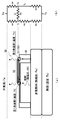
まず、基板21及び22の熱抵抗値が、“0”と見なせる(測定対象物の非発熱部の熱抵抗値よりも十分に小さい)場合を考える。この場合、内部温度センサ20による測定対象物の内部温度の測定時には、図7の(a)に模式的に示してあるような形で各部間を熱(実線/波線矢印)が移動する熱回路が形成されることになる。この熱回路は、図7の(b)に示した電気回路として表せるものであるが、当該電気回路におけるIh’の値は、R4>>R2である(R4の値が、R2の値に比べて非常に大きい)場合、Ihの値とほぼ一致する。そして、熱流束センサ30の薄膜部31の第2測温部は空気と接しているため、内部温度センサ20(熱流束センサ30)については、R4>>R2が成立する。
従って、測定対象物に接触させた内部温度センサ20が熱平衡状態になると、熱流束センサ30の薄膜部31内を第2測温部側から第1測温部側に向かって単位時間内に流れる熱量Q1と、熱流束センサ30の支持部35に非発熱体(測定対象物)側から単位時間内に流入する熱量Q2とがほぼ一致することになる。
さらに、内部温度センサ20が熱平衡状態になっている場合、Q1、Q2は、それぞれ、以下の(3)、(4)式により算出できる。
Q1=(Th-Tl)/R2 …(3)
Q2=(Tb-Tr)/Rx …(4)
尚、Th、Tlは、それぞれ、第2測温部の温度、第1測温部の温度であり、Trは、温度センサ41により測定される、支持部35の下端の温度(非発熱体表面の温度)である。
Q1=(Th-Tl)/R2 …(3)
Q2=(Tb-Tr)/Rx …(4)
尚、Th、Tlは、それぞれ、第2測温部の温度、第1測温部の温度であり、Trは、温度センサ41により測定される、支持部35の下端の温度(非発熱体表面の温度)である。
そして、Q1≒Q2であり、Th-Tl=ΔTなのであるから、内部温度センサ20が熱平衡状態となっている場合、以下の(5)式がほぼ成立することになる。
ΔT/R2 =(Tb-Tr)/Rx …(5)
ΔT/R2 =(Tb-Tr)/Rx …(5)
この(5)式は、以下の(6)式と同値である。
Tb = Tr+(Rx/R2)ΔT …(6)
Tb = Tr+(Rx/R2)ΔT …(6)
そして、(6)式中の“Rx/R2”値は、内部温度センサ20の構造(各部のサイズ、各部の構成材料等)と測定対象物とにより、適切な値が一意に定まる値である。従って、熱流束センサ30及び温度センサ41によってそれぞれ測定された温度差ΔT及び温度Trとから、上記(6)式により内部温度Tbを算出できることになる。
また、基板21及び22の熱抵抗値が“0”と見なせない場合には、(6)式中のRxを、“Rx+基板21及び22の熱抵抗値”(以下、Rx′と表記する)に置き換えた以下の(7)式でTbを算出できることになる。
Tb = Tr+(Rx′/R2)ΔT …(7)
Tb = Tr+(Rx′/R2)ΔT …(7)
この(7)式中の“Rx′/R2”値も、内部温度センサ20の構造と測定対象物とにより、適切な値が一意に定まる値である。従って、基板21及び22の熱抵抗値が“0”と見なせない場合にも、温度差ΔT及び温度Trから内部温度Tbを算出することが出来る。
尚、“Rx′/R2”値や“Rx/R2”値として使用すべき値は、いずれも、以下の(8)式の誤差が最小となるk値である。
Tb = Tr+kΔT …(8)
Tb = Tr+kΔT …(8)
そして、そのようなk値は、例えば、内部温度を変えた測定対象物(又は測定対象物を模した物体)のΔT、Trの測定を内部温度センサ20を用いて何回か行い、その結果に基づき、最小二乗法等によって求めることが出来る。従って、本内部温度センサ20は、基板21及び22の熱抵抗値が“0”と見なせるか否かを考慮することなく、内部温度Tbの算出式((8)式)を決定することが出来るものとなっていることになる。
ここで、薄膜部31内に形成されているTiN層(図5及び図6における“TiN”)について補足説明を行っておくことにする。
上記した(8)式から明らかなように、本実施形態に係る内部温度センサ20は、熱流速センサ30により測定されるΔT値が大きくなるようにしておいた方が、感度が向上するものである。そして、図7から明らかなように、第1測温部からの上方への放熱量がより大きくなるようにしておいた方が、ΔT値が大きくなるし、第1測温部からの上方への放熱量をより大きくするためには、熱放出を促すための赤外線吸収・放射層を設けておくことが有効である。そのため、薄膜部31の第1測温部及びその近傍の部分に、TiN層を設けているのである。
尚、第1測温部からの上方への放熱量を促すことは、第1測温部の上面に微小な凹凸を形成することによっても実現できる。従って、赤外線吸収・放射層を設ける代わりに、第1測温部の上面に微小な凹凸を形成しておいても、第1測温部に赤外線吸収・放射層を設けると共に、第1測温部の上面に微小な凹凸を形成しておいても良い。
以下、演算回路23(図1)について説明する。
内部温度センサ20に使用(搭載)する演算回路23は、温度差ΔTと温度Trとから内部温度Tbを算出できる回路であれば良い。
従って、演算回路23として、『温度差ΔTと温度Trとから、予め設定されているk値を用いて(8)式により内部温度Tbを算出する回路』を使用することが出来る。また、演算回路23として、そのような回路にk値の変更を受け付ける機能を付加した回路(ターミナル24を介してk値の変更を指示するコマンドが入力されると当該コマンドに従ってk値を変更する回路)を使用することも出来る。
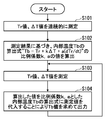
さらに、演算回路23として、所定の条件が満たされたときに、図8に示した手順の内部温度測定処理を開始する回路を使用することも出来る。尚、所定の条件としては、『ターミナル24に所定のコマンドが入力された』といった条件や、『温度Tr(温度センサ41により測定された温度)が上昇し始めた』(つまり、基板21の下面が測定対象物に接触した)といった条件を採用することが出来る。
図8に示してあるように、この内部温度測定処理を開始した演算回路23は、まず、Tr値及びΔT値を、連続的に(周期的に)、測定する処理(ステップS101)を行う。この処理としては、通常、内部温度センサ20が熱平衡に達する前に終了する処理(例えば、ΔT値の変化率が既定値以下となったときに終了する処理)が行われる。尚、既に説明した構成から明らかなように、ステップS101にて実際に行われる処理は、Tr値(温度センサ41による温度の測定結果)を表しているデータと、ΔT値(熱流速センサ30による温度差の測定結果)を表しているデータとを、連続的にASIC40から収集する処理である。
ステップS101の処理を終えた演算回路23は、Tr値及びΔT値の測定結果(ASIC40から収集したデータ群)に基づき、以下に示す『熱平衡に達する前にも成立する内部温度Tbの算出式』の係数k,aの値を算出する処理(ステップS102)を行う。
Tb = Tr+kΔT+a(dTr/dt) …(9)
Tb = Tr+kΔT+a(dTr/dt) …(9)
具体的には、このステップS102にて、演算回路23は、以下の処理を行う。
演算回路23は、まず、ステップS101の処理時に収集した測定結果の中から、異なる時刻t1,t2,t3(t1<t2<t3)に測定された3つの測定結果(Tr値とΔT値のペア)を選択する。以下、時刻tm(m=1~3)に測定されたTr値、ΔT値のことを、それぞれ、Trm、ΔTmと表記する。
次いで、演算回路23は、時刻t1におけるdTr/dt値(以下、dTr1/dtと表記する)、時刻t2におけるdTr/dt値(以下、dTr2/dtと表記する)及び時刻t3におけるdTr/dt値(以下、dTr3/dtと表記する)を算出する。
尚、上記したTr1~Tr3、ΔT1~ΔT3の選択方法は、特に限定されない。ただし、図9に例示してあるように、値が近い2Tr値や2ΔT値が存在しないように、Tr1~Tr3、ΔT1~ΔT3を選択しておくことが好ましい。何故ならば、そのようにTr1~Tr3、ΔT1~ΔT3を選択しておけば、k値及びa値を精度良く算出できるからである。
Tr1~Tr3、ΔT1~ΔT3の選択及びdTr1/dt~dTr3/dtの算出を終えた演算回路23は、以下の連立方程式を解くことにより、k値及びa値を算出する処理を行う。
Tb = Tr1+kΔT1+a(dTr1/dt)
Tb = Tr2+kΔT2+a(dTr2/dt)
Tb = Tr3+kΔT3+a(dTr3/dt)
Tb = Tr1+kΔT1+a(dTr1/dt)
Tb = Tr2+kΔT2+a(dTr2/dt)
Tb = Tr3+kΔT3+a(dTr3/dt)
より具体的には、演算回路23は、上記3式から求められたa値の算出式及びk値の算出式のそれぞれに、Tr1~Tr3、ΔT1~ΔT3及びdTr1/dt~dTr3/dtを代入することによって、k値及びa値を算出する処理を行う。
上記のような手順でk値及びa値を算出した演算回路23は、ステップS102の処理を終了する。そして、演算回路23は、Tr値及びΔT値を測定する処理(ステップS103)と、k値及びa値として算出値を設定した内部温度Tbの算出式((9)式)に測定したTr値及びΔT値を代入することにより内部温度Tbを算出して出力する処理(ステップS104)とを繰り返す状態となる。
尚、ステップS104の処理は、算出した内部温度Tbをターミナル24から出力(送信)する処理であっても、算出した内部温度Tbを、計測装置(ターミナル24を介して内部温度センサ20と接続される装置)がアクセス可能な演算回路23内のメモリに出力(記憶)する処理であっても良い。
以上、説明した処理手順から明らかなように、図7に示した手順の内部温度算出処理は、熱平衡に達する前にも成立する内部温度Tbの算出式((9)式)を用いて内部温度Tbを算出するものであると共に、当該算出式の係数a、kの値を自動的に算出するものとなっている。従って、この内部温度算出処理を実行できる演算回路23を用いておけば、測定対象物が何であっても、熱平衡状態に達する前に正確な内部温度Tbを測定できる内部温度センサ20を実現できることになる。
以上、説明したように、本実施形態に係る内部温度センサ20が備える熱流束センサ30は、小型であるが故に、熱容量が小さいもの(つまり、各部の温度が短時間で安定するもの)となっている。また、熱流束センサ30は、サーモパイル32により温度差を測定するものであるが故に、温度差の測定精度が高いものともなっている。
さらに、縦型のサーモパイルを製造するのは困難であるが、サーモパイル32のような横型のサーモパイルは容易に製造することが出来る。そして、横型のサーモパイル32を備えた熱流束センサ30によって測定されるΔTを用いても、上記したように、測定対象物の内部温度Tbを測定(算出)することが出来る。
従って、本実施形態に係る内部温度センサ20を用いておけば、測定対象物の内部温度を、応答性良く、正確に測定できることになる。尚、図2~4に示したサイズの熱流束センサ30を搭載した内部温度センサ20については、各種実験結果から、長くても3分待てば測定結果が安定することが確認できている。
《第2実施形態》
図10に、本発明の第2実施形態に係る内部温度センサ20bの概略構成を示す。
この内部温度センサ20bは、上記した第1実施形態に係る内部温度センサ20と共通する部分が多いものである。そのため、以下では、内部温度センサ20と異なる部分を中心に、内部温度センサ20bの構成及び機能を説明することにする。
図10に、本発明の第2実施形態に係る内部温度センサ20bの概略構成を示す。
この内部温度センサ20bは、上記した第1実施形態に係る内部温度センサ20と共通する部分が多いものである。そのため、以下では、内部温度センサ20と異なる部分を中心に、内部温度センサ20bの構成及び機能を説明することにする。
図10に示してあるように、内部温度センサ20bは、主基板21と、主基板21上に配設されたセンサ基板22、演算回路23及びターミナル24と、センサ基板22上に配設された熱流束センサ30及びASIC40とを、備える。これらの部材/回路は、いずれも、内部温度センサ20が備える同一名称/符号の部材/回路と同じものである。
また、内部温度センサ20bも、熱流束センサ30及びASIC40を覆うためのハウジング50bを備えている。ただし、内部温度センサ20bのハウジング50bは、図示してあるように、ハウジング50(図1参照)の天板53をヒートシンク55に変えたものとなっている。
さらに、内部温度センサ20bの熱流束センサ30上には、第2測温部保温構造36が配設されている。図8には、簡略化した形で示してあるが、この第2測温部保温構造36は、第1測温部に対向する部分と周部以外の部分が凹んだ形状を有する部材となっている。
そして、内部温度センサ20bの第2測温部保温構造36とヒートシンク55とは、熱伝導性の良い材料(例えば、アルミニウム)製の高熱伝導性部材37によって接続される。
要するに、この第2実施形態に係る内部温度センサ20bは、第1測温部の温度が外気温と一致するように、且つ、第2測温部が保温されるように(第2測温部からの上方への放熱量が過度に大きくならないように)、内部温度センサ20を変形/改良したものとなっている。
従って、内部温度センサ20bを用いておけば、内部温度センサ20を用いた場合よりも、測定対象物の内部温度を高精度に測定できることになる。
《第3実施形態》
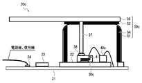
以下、図11を用いて、本発明の第3実施形態に係る内部温度センサ20cの構成を、上記した内部温度センサ20、20bと異なる部分を中心に説明する。
以下、図11を用いて、本発明の第3実施形態に係る内部温度センサ20cの構成を、上記した内部温度センサ20、20bと異なる部分を中心に説明する。
図11に示してあるように、本実施形態に係る内部温度センサ20cのセンサ基板22上には、熱流束センサ30cと、ASIC40cとが配設されている。
ASIC40cは、上記したASIC40から温度センサ41(温度センサ41として機能するダイオード及び抵抗)を取り除いたものに相当する集積回路である。熱流束センサ30cは、図12に模式的に示してあるように、温度センサ41(ASIC40から取り除いたダイオード等)が形成された薄膜部31cを有するセンサである。要するに、熱流束センサ30cは、第2測温部の温度を直接測定できるように、熱流束センサ30を改良したものとなっている。尚、詳細説明は省略するが、温度センサ41により測定される温度が第2測温部の温度であっても、上記した(8)式又は(9)式により内部温度Tbを算出することが出来る。従って、この内部温度センサ20cには、内部温度センサ20と同様に、温度差ΔTと温度Trとから、予め設定されているk値を用いて(8)式により内部温度Tbを算出する演算回路23、内部温度測定処理(図8)を実行できる演算回路23等を搭載しておくことが出来る。
また、図11と図10とを比較すれば明らかなように、内部温度センサ20cが備えるハウジング50cは、ハウジング50bのヒートシンク55を、比較的に大面積の放熱板56に変えたものとなっている。さらに、内部温度センサ20cは、高熱伝導性部材37を、熱伝導性の良い軟質素材58(例えば、伝熱性シリコーンゴムやシリコーングリース)によって、熱流束センサ30cの薄膜部31の第1測温部(図2参照)に接続した構成を有している。
以上、説明したように、本実施形態に係る内部温度センサ20cが備える熱流束センサ30cも、熱容量が小さいが故に、各部の温度が短時間で安定するものであると共に、サーモパイル32により温度差を測定するものであるが故に、温度差の測定精度が高いものとなっている。
従って、本実施形態に係る内部温度センサ20cを用いておいても、測定対象物の内部温度を、応答性良く、正確に測定できることになる。
《変形形態》
上記した各実施形態に係る内部温度センサ(20、20b、20c)は、各種の変形を行うことが出来るものである。例えば、内部温度センサ20c(図11)を、放熱板56の代わりにヒートシンク55を備えたセンサに変形することが出来る。また、内部温度センサ20、20bを、熱流束センサ30及びASIC40ではなく、熱流束センサ30c及びASIC40cを備えたセンサに変形することが出来る。
上記した各実施形態に係る内部温度センサ(20、20b、20c)は、各種の変形を行うことが出来るものである。例えば、内部温度センサ20c(図11)を、放熱板56の代わりにヒートシンク55を備えたセンサに変形することが出来る。また、内部温度センサ20、20bを、熱流束センサ30及びASIC40ではなく、熱流束センサ30c及びASIC40cを備えたセンサに変形することが出来る。
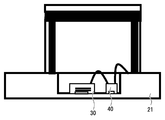
また、図13Aに模式的に示してあるように、主基板21として、熱流束センサ30及びASIC40を搭載する部分を薄くしたものを採用することも出来る。さらに、主基板21の平均的な熱抵抗を下げるために、図13Bに模式的に示したように、主基板21に複数のスルーホールを形成し、形成した各スルーホール内に金属29を充填しておくことも出来る。
また、Al層等の赤外線反射層を反射面を上側にして薄膜部内、第1、第2測温部上に形成しておくことも出来る。ただし、赤外線反射層により熱が伝導し、薄膜部31の第1測温部と第2測温部の温度差が少なくなってしまったのでは、センサとしての性能が悪くなってしまう。そのため、赤外線反射層は、熱電導率が低い材料により形成しておくことが好ましい。また、比較的に熱電導率が高い材料で赤外線反射層を形成する場合には、図14に模式的に示したように、第2測温部側と中央部(第1測温部)側とに分けた形で赤外線反射層を形成しておくことが望ましい。また、第2測温部の赤外線反射膜は下側にも反射面を設けると保温効果により、高精度化が期待できる。尚、図14に示したような構造を採用しておけば、薄膜部31の上面に向けて外部から照射された赤外線を反射して当該赤外線による薄膜部31の加熱を防止することが出来る。従って、当該構造は、内部温度センサ20を、ハウジング50を備えないセンサとして実現する場合に、特に有効な構造であるということが出来る。
各実施形態に係る内部温度センサを、演算回路23を備えていないセンサ(ASIC40、40cの出力をそのまま出力するセンサ)や、熱流束センサ30、30c、温度センサ41の出力そのまま出力するセンサに変形することも出来る。ただし、熱流束センサ30、30c、温度センサ41の出力そのまま出力すると、ノイズの影響を受けやすくなる。そのため、内部温度センサには、各センサの出力を増幅する増幅器を搭載しておくことが好ましい。
演算回路23を、各センサによる時系列的な温度差、温度の測定結果に基づき、熱伝導方程式を解くことにより、測定対象物の内部温度を算出する回路に変形することも出来る。
また、内部温度センサ20の各部のサイズは、適宜変更することが出来る。例えば、図1に示した内部温度センサ20は、断熱材52、天板53が比較的に薄いものとなっている。ただし、断熱材52や天板53の厚さは特に限定されないので、例えば、図15に示したように、断熱材52として厚い発泡ウレタンを用い、天板53として厚い導電フォーム上に赤外線反射板としてのアルミ箔を貼り付けたものを用いることも出来る。
熱流束センサ30の薄膜部31下に、熱伝導性の悪い物質を挿入(充填)しておくことも出来る。さらに、ハウジング50内に空気以外の気体を封入しておくことも、ハウジング50内を真空にしておくことも出来る。
20,20b,20c 内部温度センサ
21 主基板
22 センサ基板
23 演算回路
24 ターミナル
29 金属
30,30c 熱流束センサ
31,31c 薄膜部
32 サーモパイル
35 支持部
36 第2測温部保温構造
37 高熱伝導性部材
40,40c ASIC
41 温度センサ
50,50b,50c ハウジング
51 側壁部
52 断熱材
53 天板
54 赤外線吸収体
55 ヒートシンク
56 放熱板
58 軟質素材
21 主基板
22 センサ基板
23 演算回路
24 ターミナル
29 金属
30,30c 熱流束センサ
31,31c 薄膜部
32 サーモパイル
35 支持部
36 第2測温部保温構造
37 高熱伝導性部材
40,40c ASIC
41 温度センサ
50,50b,50c ハウジング
51 側壁部
52 断熱材
53 天板
54 赤外線吸収体
55 ヒートシンク
56 放熱板
58 軟質素材
Claims (11)
- 測定対象物の内部温度の測定時に、その一方の面を前記測定対象物の表面に接触させる基材と、
前記基材の他方の面上に設けられた、MEMS(Micro Electro Mechanical Systems)プロセスにより製造された熱流束センサであって、第1測温部及び第2測温部を有し、前記第1測温部と前記第2測温部との間の温度差を検出するサーモパイルが形成されている薄膜部を含み、前記基材を介して流入する前記測定対象物からの熱を前記第2測温部に伝導する熱伝導性部材により、前記第1測温部と前記基材との間に空間が存在し、且つ、前記基材に対して平行となるように、前記薄膜部が支持された熱流束センサと、
前記基材の前記熱伝導性部材と接触している部分の温度又は前記薄膜部の前記第2測温部の温度を測定するための温度センサと、
を備えることを特徴とする内部温度センサ。 - 前記熱流束センサの薄膜部は、前記第1測温部からの放熱を促すための放熱促進構造を含む
ことを特徴とする請求項1に記載の内部温度センサ。 - 前記熱流束センサの薄膜部は、前記薄膜部の前記基材と対向しない側の面に向けて照射された赤外線を反射して当該赤外線による前記薄膜部の加熱を防止する赤外線反射構造を含む
ことを特徴とする請求項1に記載の内部温度センサ。 - 前記熱流束センサと前記温度センサとを覆うハウジングを、さらに備える
ことを特徴とする請求項1から3のいずれか一項に記載の内部温度センサ。 - 前記ハウジングの内面に赤外線吸収体が配置されている
ことを特徴とする請求項4に記載の内部温度センサ。 - 前記ハウジングの外面は赤外線及び電磁波を反射する
ことを特徴とする請求項4又は5に記載の内部温度センサ。 - 前記ハウジングは、前記熱流束センサ及び前記温度センサを囲む側壁部と、前記側壁部の開口部側の端面に設けられた断熱材と、前記断熱材を介して前記側壁部に対して取り付けられた、前記側壁部の開口部を覆う天板とを含む
ことを特徴とする請求項4から6のいずれか一項に記載の内部温度センサ。 - 前記天板が、ヒートシンク又は放熱板であることを特徴とする請求項7に記載の内部温度センサ。
- 前記薄膜部の前記第1測温部からの熱を前記天板に伝達するための部材をさらに備える
ことを特徴とする請求項7又は8に記載の内部温度センサ。 - 前記熱流束センサの出力と前記温度センサの出力とを増幅する増幅器をさらに備える
ことを特徴とする請求項1から9のいずれか一項に記載の内部温度センサ。 - 前記増幅器により増幅された前記熱流束センサの出力と前記温度センサの出力とに基づき、前記測定対象物の内部温度を算出する演算部をさらに備える
ことを特徴とする請求項10に記載の内部温度センサ。
Priority Applications (3)
| Application Number | Priority Date | Filing Date | Title |
|---|---|---|---|
| US15/103,366 US10060803B2 (en) | 2013-12-13 | 2014-12-12 | MEMS internal temperature sensor having thin film thermopile |
| CN201480062132.5A CN105745518B (zh) | 2013-12-13 | 2014-12-12 | 内部温度传感器 |
| DE112014005627.8T DE112014005627B4 (de) | 2013-12-13 | 2014-12-12 | Innentemperatursensor |
Applications Claiming Priority (2)
| Application Number | Priority Date | Filing Date | Title |
|---|---|---|---|
| JP2013258686A JP6349713B2 (ja) | 2013-12-13 | 2013-12-13 | 内部温度センサ |
| JP2013-258686 | 2013-12-13 |
Publications (1)
| Publication Number | Publication Date |
|---|---|
| WO2015088024A1 true WO2015088024A1 (ja) | 2015-06-18 |
Family
ID=53371321
Family Applications (1)
| Application Number | Title | Priority Date | Filing Date |
|---|---|---|---|
| PCT/JP2014/083042 Ceased WO2015088024A1 (ja) | 2013-12-13 | 2014-12-12 | 内部温度センサ |
Country Status (5)
| Country | Link |
|---|---|
| US (1) | US10060803B2 (ja) |
| JP (1) | JP6349713B2 (ja) |
| CN (1) | CN105745518B (ja) |
| DE (1) | DE112014005627B4 (ja) |
| WO (1) | WO2015088024A1 (ja) |
Cited By (1)
| Publication number | Priority date | Publication date | Assignee | Title |
|---|---|---|---|---|
| US20240060832A1 (en) * | 2022-08-18 | 2024-02-22 | Apple Inc. | Dual heat path temperature sensor |
Families Citing this family (25)
| Publication number | Priority date | Publication date | Assignee | Title |
|---|---|---|---|---|
| JP6428397B2 (ja) * | 2015-03-12 | 2018-11-28 | オムロン株式会社 | 内部温度測定装置及び温度差測定モジュール |
| JP6428398B2 (ja) * | 2015-03-12 | 2018-11-28 | オムロン株式会社 | 内部温度測定装置及び熱抵抗測定装置 |
| JP6582769B2 (ja) * | 2015-09-08 | 2019-10-02 | 株式会社デンソーウェーブ | 電子機器 |
| US10338016B1 (en) * | 2015-09-28 | 2019-07-02 | Jeffrey Callister | Verification of material composition in precious metal object |
| JP6763142B2 (ja) * | 2015-12-28 | 2020-09-30 | セイコーエプソン株式会社 | 内部温度測定装置、リスト装着型装置及び内部温度測定方法 |
| JP2017181239A (ja) * | 2016-03-30 | 2017-10-05 | 株式会社デンソー | 温度計測装置及び温度計測方法 |
| WO2018033795A2 (en) | 2016-08-19 | 2018-02-22 | Thalman Health Ltd. | System and method for monitoring core body temperature |
| WO2018033799A1 (en) | 2016-08-19 | 2018-02-22 | Thalman Health Ltd. | Method and system for determination of core body temperature |
| CH713267A1 (de) * | 2016-12-21 | 2018-06-29 | Greenteg Ag | Sensoreinheit für ein tragbares Computersystem und Integration der Sensoreinheit in das Gehäuse des Computersystems. |
| JP2018151322A (ja) * | 2017-03-14 | 2018-09-27 | オムロン株式会社 | 内部温度測定装置 |
| WO2018180800A1 (ja) | 2017-03-31 | 2018-10-04 | 日本電気株式会社 | 温度拡散係数計測装置、それを用いた深部体温計、深部体温計測装置、および深部体温計測方法 |
| CN107560748B (zh) * | 2017-08-09 | 2020-01-24 | 深圳艺点创新科技有限公司 | 具有温度信号输出的电热陶瓷装置和温度监测方法 |
| JP7065308B2 (ja) * | 2018-04-10 | 2022-05-12 | パナソニックIpマネジメント株式会社 | 発熱量測定方法および発熱量測定装置 |
| DE102018122940B4 (de) * | 2018-09-19 | 2026-04-09 | HELLA GmbH & Co. KGaA | Sensoranordnung zur Messung der Temperatur einer Scheibe |
| KR102603059B1 (ko) * | 2018-09-21 | 2023-11-16 | 현대자동차주식회사 | 차량의 실내온도 측정장치 및 측정방법 |
| EP3994435A4 (en) | 2019-07-01 | 2022-08-24 | Thermasense Corp. | DEVICE, SYSTEMS AND METHODS FOR NON-INVASIVE THERMAL INQUIRY |
| US11174153B2 (en) | 2019-08-21 | 2021-11-16 | Invensense, Inc. | Package level thermal gradient sensing |
| US11186479B2 (en) | 2019-08-21 | 2021-11-30 | Invensense, Inc. | Systems and methods for operating a MEMS device based on sensed temperature gradients |
| US11073531B2 (en) | 2019-08-21 | 2021-07-27 | Invensense, Inc. | Vertical thermal gradient compensation in a z-axis MEMS accelerometer |
| WO2021199378A1 (ja) * | 2020-04-01 | 2021-10-07 | 日本電信電話株式会社 | 測定装置 |
| WO2022004098A1 (ja) * | 2020-06-30 | 2022-01-06 | アルプスアルパイン株式会社 | センサーユニットおよびその取り付け構造 |
| CN112067651B (zh) * | 2020-08-10 | 2021-11-05 | 中国科学院空间应用工程与技术中心 | 一种驻留式外星体内部热流测量热探针以及测量方法 |
| GB2643369A (en) * | 2021-06-14 | 2026-02-11 | Analog Devices International Unlimited Co | Sensing assembly |
| US12474223B2 (en) * | 2021-09-24 | 2025-11-18 | Apple Inc. | Temperature sensing systems and methods including multiple temperature sensors |
| WO2026058906A1 (ja) * | 2024-09-11 | 2026-03-19 | TopoLogic株式会社 | 熱流束測定システム、及び熱流束測定方法 |
Citations (4)
| Publication number | Priority date | Publication date | Assignee | Title |
|---|---|---|---|---|
| JPS6010138A (ja) * | 1983-06-30 | 1985-01-19 | Toshiba Corp | 熱流束測定装置 |
| JPS61239127A (ja) * | 1985-04-15 | 1986-10-24 | Natl Space Dev Agency Japan<Nasda> | 熱流束センサ |
| JP2002372464A (ja) * | 2001-04-11 | 2002-12-26 | Omron Corp | 電子体温計 |
| JP2013210327A (ja) * | 2012-03-30 | 2013-10-10 | Citizen Holdings Co Ltd | 接触式内部温度計 |
Family Cites Families (16)
| Publication number | Priority date | Publication date | Assignee | Title |
|---|---|---|---|---|
| JPS6140634U (ja) * | 1984-08-18 | 1986-03-14 | オムロン株式会社 | 電子温度計 |
| DE19800753A1 (de) | 1998-01-12 | 1999-07-22 | Siemens Ag | Sensor für und Verfahren betreffend nicht-invasive Temperaturmessung, insbesondere für den Einsatz in der Prozeßtechnik |
| EP1249691A1 (en) * | 2001-04-11 | 2002-10-16 | Omron Corporation | Electronic clinical thermometer |
| US10227063B2 (en) * | 2004-02-26 | 2019-03-12 | Geelux Holdings, Ltd. | Method and apparatus for biological evaluation |
| JP2007212407A (ja) | 2006-02-13 | 2007-08-23 | Kanazawa Univ | 非加熱型深部体温計およびそれを用いた深部体温測定装置 |
| DE102006012338B3 (de) | 2006-03-17 | 2007-07-19 | Drägerwerk AG | Anordnung zum Messen der Kerntemperatur eines Körpers |
| JP5509443B2 (ja) * | 2008-02-27 | 2014-06-04 | 日本モレックス株式会社 | 測定装置及び熱伝導率推定方法 |
| CN102458232A (zh) | 2009-04-15 | 2012-05-16 | 亚利桑特保健公司 | 深部组织温度探测器结构 |
| CN102401699B (zh) * | 2010-09-17 | 2015-08-19 | 三菱综合材料株式会社 | 温度传感器 |
| JP5647022B2 (ja) | 2011-01-27 | 2014-12-24 | テルモ株式会社 | 体温計 |
| US9846085B2 (en) * | 2012-07-25 | 2017-12-19 | Nxstage Medical, Inc. | Fluid property measurement devices, methods, and systems |
| JP6225766B2 (ja) * | 2014-03-13 | 2017-11-08 | オムロン株式会社 | 内部温度測定方法及び内部温度測定装置 |
| JP6350212B2 (ja) * | 2014-10-27 | 2018-07-04 | オムロン株式会社 | 内部温度測定装置 |
| JP6398810B2 (ja) * | 2015-03-12 | 2018-10-03 | オムロン株式会社 | 内部温度測定装置及び温度差測定モジュール |
| JP6398807B2 (ja) * | 2015-03-12 | 2018-10-03 | オムロン株式会社 | 温度差測定装置 |
| JP6398808B2 (ja) * | 2015-03-12 | 2018-10-03 | オムロン株式会社 | 内部温度測定装置及びセンサパッケージ |
-
2013
- 2013-12-13 JP JP2013258686A patent/JP6349713B2/ja not_active Expired - Fee Related
-
2014
- 2014-12-12 DE DE112014005627.8T patent/DE112014005627B4/de not_active Expired - Fee Related
- 2014-12-12 WO PCT/JP2014/083042 patent/WO2015088024A1/ja not_active Ceased
- 2014-12-12 CN CN201480062132.5A patent/CN105745518B/zh not_active Expired - Fee Related
- 2014-12-12 US US15/103,366 patent/US10060803B2/en active Active
Patent Citations (4)
| Publication number | Priority date | Publication date | Assignee | Title |
|---|---|---|---|---|
| JPS6010138A (ja) * | 1983-06-30 | 1985-01-19 | Toshiba Corp | 熱流束測定装置 |
| JPS61239127A (ja) * | 1985-04-15 | 1986-10-24 | Natl Space Dev Agency Japan<Nasda> | 熱流束センサ |
| JP2002372464A (ja) * | 2001-04-11 | 2002-12-26 | Omron Corp | 電子体温計 |
| JP2013210327A (ja) * | 2012-03-30 | 2013-10-10 | Citizen Holdings Co Ltd | 接触式内部温度計 |
Cited By (1)
| Publication number | Priority date | Publication date | Assignee | Title |
|---|---|---|---|---|
| US20240060832A1 (en) * | 2022-08-18 | 2024-02-22 | Apple Inc. | Dual heat path temperature sensor |
Also Published As
| Publication number | Publication date |
|---|---|
| DE112014005627T5 (de) | 2016-10-06 |
| CN105745518B (zh) | 2017-11-24 |
| US20160313193A1 (en) | 2016-10-27 |
| CN105745518A (zh) | 2016-07-06 |
| US10060803B2 (en) | 2018-08-28 |
| JP2015114291A (ja) | 2015-06-22 |
| DE112014005627B4 (de) | 2018-09-06 |
| JP6349713B2 (ja) | 2018-07-04 |
Similar Documents
| Publication | Publication Date | Title |
|---|---|---|
| JP6349713B2 (ja) | 内部温度センサ | |
| JP6398808B2 (ja) | 内部温度測定装置及びセンサパッケージ | |
| JP6225766B2 (ja) | 内部温度測定方法及び内部温度測定装置 | |
| JP6398807B2 (ja) | 温度差測定装置 | |
| JP6275830B2 (ja) | 熱流束を測定するための方法及びシステム | |
| JP6350212B2 (ja) | 内部温度測定装置 | |
| JP6398810B2 (ja) | 内部温度測定装置及び温度差測定モジュール | |
| JP5959111B2 (ja) | 熱流センサ | |
| JP6398806B2 (ja) | センサパッケージ | |
| JP6428398B2 (ja) | 内部温度測定装置及び熱抵抗測定装置 | |
| JP2013228269A (ja) | 熱流束測定装置及び熱流束測定方法 | |
| JP6428397B2 (ja) | 内部温度測定装置及び温度差測定モジュール | |
| JP6820789B2 (ja) | 赤外線センサ装置 | |
| CN109891205B (zh) | 传感器以及操作传感器的方法 | |
| JP2015197371A (ja) | サーモパイル素子およびガス検知器 | |
| JP2007033053A (ja) | 熱型赤外線検出器を用いた放射温度計 |
Legal Events
| Date | Code | Title | Description |
|---|---|---|---|
| 121 | Ep: the epo has been informed by wipo that ep was designated in this application |
Ref document number: 14869898 Country of ref document: EP Kind code of ref document: A1 |
|
| WWE | Wipo information: entry into national phase |
Ref document number: 15103366 Country of ref document: US |
|
| WWE | Wipo information: entry into national phase |
Ref document number: 112014005627 Country of ref document: DE |
|
| 122 | Ep: pct application non-entry in european phase |
Ref document number: 14869898 Country of ref document: EP Kind code of ref document: A1 |