WO2015087897A1 - 基板処理装置および基板処理方法 - Google Patents
基板処理装置および基板処理方法 Download PDFInfo
- Publication number
- WO2015087897A1 WO2015087897A1 PCT/JP2014/082635 JP2014082635W WO2015087897A1 WO 2015087897 A1 WO2015087897 A1 WO 2015087897A1 JP 2014082635 W JP2014082635 W JP 2014082635W WO 2015087897 A1 WO2015087897 A1 WO 2015087897A1
- Authority
- WO
- WIPO (PCT)
- Prior art keywords
- substrate
- reference member
- pressing member
- pressing
- substrate processing
- Prior art date
- Legal status (The legal status is an assumption and is not a legal conclusion. Google has not performed a legal analysis and makes no representation as to the accuracy of the status listed.)
- Ceased
Links
Images







Classifications
-
- H—ELECTRICITY
- H10—SEMICONDUCTOR DEVICES; ELECTRIC SOLID-STATE DEVICES NOT OTHERWISE PROVIDED FOR
- H10P—GENERIC PROCESSES OR APPARATUS FOR THE MANUFACTURE OR TREATMENT OF DEVICES COVERED BY CLASS H10
- H10P72/00—Handling or holding of wafers, substrates or devices during manufacture or treatment thereof
- H10P72/50—Handling or holding of wafers, substrates or devices during manufacture or treatment thereof for positioning, orientation or alignment
-
- H—ELECTRICITY
- H10—SEMICONDUCTOR DEVICES; ELECTRIC SOLID-STATE DEVICES NOT OTHERWISE PROVIDED FOR
- H10P—GENERIC PROCESSES OR APPARATUS FOR THE MANUFACTURE OR TREATMENT OF DEVICES COVERED BY CLASS H10
- H10P72/00—Handling or holding of wafers, substrates or devices during manufacture or treatment thereof
- H10P72/50—Handling or holding of wafers, substrates or devices during manufacture or treatment thereof for positioning, orientation or alignment
- H10P72/53—Handling or holding of wafers, substrates or devices during manufacture or treatment thereof for positioning, orientation or alignment using optical controlling means
-
- G—PHYSICS
- G02—OPTICS
- G02F—OPTICAL DEVICES OR ARRANGEMENTS FOR THE CONTROL OF LIGHT BY MODIFICATION OF THE OPTICAL PROPERTIES OF THE MEDIA OF THE ELEMENTS INVOLVED THEREIN; NON-LINEAR OPTICS; FREQUENCY-CHANGING OF LIGHT; OPTICAL LOGIC ELEMENTS; OPTICAL ANALOGUE/DIGITAL CONVERTERS
- G02F1/00—Devices or arrangements for the control of the intensity, colour, phase, polarisation or direction of light arriving from an independent light source, e.g. switching, gating or modulating; Non-linear optics
- G02F1/01—Devices or arrangements for the control of the intensity, colour, phase, polarisation or direction of light arriving from an independent light source, e.g. switching, gating or modulating; Non-linear optics for the control of the intensity, phase, polarisation or colour
- G02F1/13—Devices or arrangements for the control of the intensity, colour, phase, polarisation or direction of light arriving from an independent light source, e.g. switching, gating or modulating; Non-linear optics for the control of the intensity, phase, polarisation or colour based on liquid crystals, e.g. single liquid crystal display cells
- G02F1/1303—Apparatus specially adapted to the manufacture of LCDs
Definitions
- the present invention relates to a substrate processing apparatus and a substrate processing method, and more particularly, to a substrate processing apparatus and a substrate processing method capable of positioning the substrate on a substrate and a mounting surface to be mounted.
- a substrate processing apparatus for processing or inspecting a substrate such as a flat panel display (FPD) such as a liquid crystal display or an electroluminescence (EL) display is known.
- a substrate which is a processing target material, is mounted on a mounting surface of a holding table, and a predetermined process is performed after positioning (alignment) of the substrate (for example, Japanese Patent Application Laid-Open No. 2003-2003). No. 29017 and JP-A-2013-125795).
- the holding table on which the substrate is fixed based on the positional information of the alignment mark formed on the substrate surface A method of moving itself using a moving member such as an XY ⁇ stage is used.
- the present invention has been made to solve the above-described problems, and an object of the present invention is to provide a substrate processing apparatus and a substrate processing method that can obtain high positioning accuracy and are low in cost.
- a substrate processing apparatus includes a holding table having a mounting surface on which a substrate is mounted, a first pressing member, a second pressing member, a first reference member, a second reference member, a pressing member moving unit, and a first reference.
- a member moving part is provided.
- the first pressing member and the first reference member are disposed so as to sandwich the substrate mounted on the holding base from the first direction along the mounting surface.
- the second pressing member and the second reference member are disposed so as to sandwich the substrate mounted on the holding base from the second direction along the mounting surface while intersecting the first direction.
- the pressing member moving unit moves the first pressing member and the second pressing member to the first reference member side and the second reference member side, respectively.
- the first reference member moving unit moves the first reference member.
- the substrate processing method includes a step of preparing a substrate, a step of mounting the substrate on the mounting surface of the holding table, and a step of positioning the substrate.
- the substrate mounted on the mounting surface is sandwiched between the first pressing member and the first reference member from the first direction along the mounting surface, and intersects with the first direction and mounted.
- the substrate is positioned by being sandwiched between the second pressing member and the second reference member from the second direction along the surface.
- the step of positioning the substrate includes a step of moving the first pressing member and the second pressing member to the first reference member side and the second reference member side, and a step of moving the first reference member, respectively.
- a substrate processing apparatus and a substrate processing method having high positioning accuracy can be realized at low cost.
- the substrate processing apparatus includes a chuck stage 4 as a holding table for mounting a substrate 1 as a processing target material on a mounting surface (upper surface), and an upper portion of the chuck stage 4.
- Reference members 5a to 5c for positioning the substrate 1 and a pressing member for pressing the end of the substrate 1 and pressing the substrate 1 against the reference members 5a to 5c. 6a and 6b, CCD cameras 10a and 10b for detecting alignment marks 3a and 3b formed on the surface of the substrate 1, these CCD cameras 10a and 10b, reference members 5a to 5c, and pressing members 6a and 6b.
- a control unit 20 for controlling the position of the main unit.
- the substrate processing apparatus is also provided with a processing unit (not shown) for inspecting and processing the substrate 1.
- the planar shape of the chuck stage 4 is rectangular.
- Electric cylinders 7a to 7c for moving a plurality of reference members 5a to 5c are installed on two adjacent sides among the four sides constituting the outer periphery of the chuck stage 4. Specifically, electric cylinders 7a and 7b for moving two reference members 5a and 5b are installed on the long side of the front side of the chuck stage 4 shown in FIG. An electric cylinder 7c for moving the reference member 5c is installed on one short side adjacent to the long side.
- the reference members 5a to 5c are connected to the tip portions of the drive shafts of the electric cylinders 7a to 7c, respectively. Further, the reference members 5 a to 5 c are arranged at positions overlapping the upper surface of the chuck stage 4.
- An air cylinder 8b for moving the pressing member 6b is connected to the other long side facing the reference members 5a and 5b.
- An air cylinder 8a for moving the pressing member 6a is connected to the other short side facing the reference member 5c.
- the pressing members 6a and 6b are connected to the tip ends of the drive shafts of the air cylinders 8a and 8b, respectively. Further, the pressing members 6 a and 6 b are arranged at positions overlapping the upper surface of the chuck stage 4. It is preferable that the speed at which the air cylinders 8a and 8b move the pressing members 6a and 6b and the pressure to press the end of the substrate 1 are adjusted in advance so that the substrate 1 is not damaged or deformed.
- the reference members 5a to 5c and the pressing members 6a and 6b may be made of any material, but for example, metal or resin can be used.
- the reference members 5a to 5c and the electric cylinders 7a to 7c preferably have sufficient rigidity or holding force so as not to be displaced or deformed when the substrate 1 is pressed.
- the reference members 5 a to 5 c and the pressing members 6 a and 6 b are cylindrical as shown in FIG. 1 and are arranged so that the cylindrical side walls are in contact with the end surface of the substrate 1.
- the shapes of the reference members 5a to 5c and the pressing members 6a and 6b other arbitrary shapes (for example, a polyhedral shape such as a rectangular parallelepiped, a spherical shape, etc.) may be adopted.
- Two CCD cameras 10a and 10b are arranged at positions facing the upper surface of the chuck stage 4.
- the CCD cameras 10a and 10b are arranged to detect alignment marks 3a and 3b formed on the surface of the substrate 1 that is a processing target material.
- Lenses 9a and 9b are attached to the CCD cameras 10a and 10b, respectively.
- the electric cylinders 7a to 7c, the air cylinders 8a and 8b, and the CCD cameras 10a and 10b are connected to the control unit 20, respectively.
- the substrate 1 as the processing target material is positioned by pressing the end portions of the chuck stage 4 on the upper surface of the chuck stage 4 by the reference members 5a to 5c and the pressing members 6a and 6b.
- a predetermined process is performed on the positioned substrate 1 by a processing unit (not shown).
- a substrate 1 that is a material to be processed is prepared.
- a pattern 2 and alignment marks 3 a and 3 b are formed on the surface of the substrate 1.
- a lattice pattern is formed.
- the substrate 1 is placed on the upper surface of the chuck stage 4 with the reference members 5a to 5c and the pressing members 6a and 6b sufficiently retracted from the center of the upper surface of the substrate 1. (Step (S10)).
- Step (S10) it is preferable that a space is formed between the end portion (end surface) of the substrate 1 and the reference members 5a to 5c and the pressing members 6a and 6b.
- step (S20) by operating the air cylinders 8a and 8b, the pressing members 6a and 6b are pressed against the end face of the substrate 1 (step (S20)). Then, by pressing and moving the substrate 1 by the pressing members 6a and 6b, the end portions of the substrate 1 facing the reference members 5a to 5c and the reference members 5a to 5c are brought into contact with each other. At this time, the positions of the reference members 5a to 5c are adjusted in advance so that the substrate 1 comes to a predetermined position when the end of the substrate 1 contacts the reference members 5a to 5c as shown in FIG. Is preferred.
- substrate 1 may not be damaged can be performed, for example, by adjusting the air supply pressure to the air cylinders 8a and 8b.
- the alignment marks 3a and 3b formed on the surface of the substrate 1 are detected by the CCD cameras 10a and 10b (see FIG. 1) (step (S30)).
- the alignment marks 3a and 3b have predetermined relative positions with respect to the pattern formed on the surface of the substrate 1. Therefore, the position of the pattern 2 formed on the surface of the substrate 1 can be specified based on the positions of the alignment marks 3a and 3b.
- the measurement position data of the alignment marks 3a and 3b is output from the CCD cameras 10a and 10b to the control unit 20.
- the position specified by the measurement position data of the alignment marks 3a and 3b is a preset position (that is, the position where the pattern 2 formed on the surface of the substrate 1 is to be disposed when undergoing processing).
- the control unit 20 determines whether or not the alignment marks 3a and 3b are at the reference positions (steps (S40)). Specifically, the control unit compares the measurement position data with the reference position data of the alignment marks 3a and 3b determined in advance.
- the reference member 5a is driven by driving the electric cylinders 7a to 7c so that the deviation is eliminated.
- the positions of .about.5c are changed (step (S50)).
- the pressing members 6a and 6b maintain a state in which a predetermined force is pressed against the end of the substrate 1 by the air cylinders 8a and 8b.
- the position of the substrate 1 is changed in accordance with the movement of the reference members 5a to 5c by the pressing force of the pressing members 6a and 6b.
- the substrate 1 is moved so that the positions of the alignment marks 3a and 3b overlap with a predetermined reference position.
- step (S30) and step (S40) are performed again. That is, the positions of the alignment marks 3 a and 3 b are measured by the CCD cameras 10 a and 10 b, and the obtained measurement position data is output to the control unit 20.
- the control unit 20 determines whether or not the position specified by the measurement position data of the alignment marks 3a and 3b is a preset reference position. In this step (S40), when it is determined that the positions of the alignment marks 3a and 3b are the reference positions, the substrate 1 is fixed to the surface of the chuck stage 4 (step (S60)).
- any method can be used as the method for fixing the substrate 1 in the above step (S60), and for example, a vacuum adsorption method or an electrostatic adsorption method can be used.
- a vacuum adsorption method or an electrostatic adsorption method can be used.
- the fixing of the substrate 1 to the chuck stage 4 is released and again.
- the above-described step (S50) is performed. Such a process is repeated until it is determined in the step (S40) that the positions of the alignment marks 3a and 3b are the reference positions, and the step (S60) is performed.
- the structure of the substrate processing apparatus can be simplified and the cost of the substrate processing apparatus can be reduced as compared with the case where a later-described process of moving the chuck stage 4 itself using an XY ⁇ stage or the like is used.
- a substrate positioning method in the substrate processing apparatus including the above-described XY ⁇ stage will be specifically described.
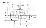
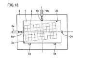
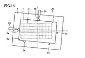
- FIGS. 10 to 14 are schematic diagrams for explaining a substrate positioning method in a substrate processing apparatus as a comparative example.
- the substrate processing apparatus shown in FIGS. 10 to 14 basically has the same structure as the substrate processing apparatus shown in FIG. 1, but the reference members 5a to 5c are located at predetermined positions on the upper surface of the chuck stage 4. It is in a fixed state. Further, the chuck stage 4 can be moved by an XY ⁇ stage (not shown).
- the substrate 1 is mounted on the upper surface of the chuck stage 4 so as not to contact the reference members 5a to 5c and the pressing members 6a and 6b.
- the pressing members 6 a and 6 b are pressed against the end of the substrate 1 by driving the air cylinders 8 a and 8 b.
- the substrate 1 is moved, and the end portions of the substrate 1 facing the reference members 5a to 5c are in contact with the reference members 5a to 5c.
- the substrate 1 is positioned at a predetermined position on the upper surface of the chuck stage 4 defined by the reference members 5a to 5c.
- the positions of the reference members 5a to 5c are set appropriately, thereby 2 and the alignment marks 3a and 3b should be in a state where they are arranged at the correct positions to be arranged at the time of processing (see FIG. 11).
- the pattern 2 is formed at a position shifted from a predetermined position on the surface of the substrate 1 (see, for example, the pattern 2 of the substrate 1 shown in FIG. 12). A substrate positioning method in such a case will be described.
- the substrate 1 is placed on the upper surface of the chuck stage 4 in the same manner as the process shown in FIG. Thereafter, the same process as that shown in FIG. 11 is performed to place the substrate 1 at a predetermined position on the upper surface of the chuck stage 4 as shown in FIG.
- the pattern 2 is formed on the surface of the substrate 1 so as to deviate from a predetermined position, the position of the pattern 2 shown in FIG. 13 is different from the region shown in FIG. It is in a state.
- the alignment marks 3a and 3b are Detect position. If it is detected that the positions of the alignment marks 3a and 3b are deviated from a predetermined reference position (the positions of the alignment marks 3a and 3b shown in FIG. 11), the positions of the alignment marks 3a and 3b are detected.
- the chuck stage 4 on which the substrate 1 is mounted is moved in the horizontal plane (in the XY plane) using the XY ⁇ stage so that the deviation is eliminated.
- the position of the pattern 2 can be corrected to the correct position at the time of processing.
- an XY ⁇ stage for moving the chuck stage 4 itself is required to position the pattern 2 at an accurate position.
- the reference members 5a to 5c are configured to be movable without using the XY ⁇ stage as described in the comparative example.
- the pattern 2 of the substrate 1 can be positioned at an accurate position.
- the surface of the chuck stage 4 in the substrate processing apparatus has air or an inert gas (for example, nitrogen gas or the like) in order to move the substrate 1 more smoothly.
- a plurality of ejection ports 21 through which gas such as argon gas is ejected are formed.
- a pipe (not shown) is connected to the jet port 21, and the gas supply device is connected to the pipe via an on-off valve. From this jet port, the substrate 1 can be floated from the surface of the chuck stage 4 by jetting, for example, compressed air in the step (S50). As a result, the substrate 1 can be moved smoothly in the step (S50).
- an elastic member 23 may be disposed between the pressing member 6a and the drive shaft 22 of the air cylinder 8a. In this way, even when the substrate 1 is pressed by the pressing member 6 a at the stroke end of the air cylinder 8 a, when the pressing member 6 a is brought into contact with the end of the substrate 1, An excessive force applied can be absorbed by the deformation of the elastic member 23. For this reason, possibility that the board
- the elastic member 23 may be disposed between the pressing member 6b and the drive shaft of the air cylinder 8b. As the elastic member 23, for example, rubber or a spring can be used.
- the reference members 5a to 5c may be movable.
- only a part of the plurality of reference members 5a to 5c in the example shown in FIGS. 7 to 9, as shown in FIGS. Only the reference member 5a
- the reference members 5b and 5c are fixed on the upper surface of the chuck stage 4, while only the reference member 5a is movable by the electric cylinder 7a.
- the substrate 1 (more specifically, the pattern 2) formed on the surface of the substrate 1 can be positioned as follows. This will be described below.
- the substrate 1 is disposed at a position where it does not come into contact with the reference members 5a to 5c and the pressing members 6a and 6b.
- This step is basically the same as the step (S10) shown in FIG.
- step (S30) to step (S50) are performed. That is, the positions of the alignment marks 3a and 3b on the surface of the substrate 1 are detected using the CCD cameras 10a and 10b (see FIG. 1).
- the substrate 1 is moved so as to eliminate the deviation.
- the position of the reference member 5a is changed by driving the electric cylinder 7a.
- the substrate 1 rotates on the upper surface of the chuck stage 4 in a plane along the upper surface. In this way, the pattern 2 of the substrate 1 is positioned at a predetermined position during processing as shown in FIG. Even in this case, the pattern 2 of the substrate 1 can be positioned.
- the three reference members 5a to 5c are arranged. If the number of the reference members is two (for example, two reference members 5a and 5c), It can be any number. Further, all of the plurality of reference members may be movable, but only a part may be connected to an electric cylinder or the like to be movable, while the other part may be fixed to the chuck stage.
- the electric cylinders 7a to 7c are used to move the reference members 5a to 5c.
- other moving members for example, an air cylinder, a hydraulic cylinder, etc.
- the air cylinders 8a and 8b are used to move the pressing members 6a and 6b
- other moving members for example, linear motion units of an arbitrary system such as an electric cylinder or a hydraulic cylinder
- a substrate processing apparatus includes a holding table (chuck stage 4) having a mounting surface (upper surface) on which a substrate 1 is mounted, a first pressing member (pressing member 6b), and a second pressing member ( A pressing member 6a), a first reference member (reference member 5a), a second reference member (reference member 5c), a pressing member moving unit (air cylinders 8a and 8b), and a first reference member moving unit (electric cylinder 7a).
- the first pressing member (6b) and the first reference member (5a) sandwich the substrate 1 mounted on the holding base (chuck stage 4) from a first direction (vertical direction in FIG. 2) along the mounting surface.
- the second pressing member (6a) and the second reference member (5c) are arranged so that the substrate 1 mounted on the holding table (chuck stage 4) intersects the first direction and extends in the second direction along the mounting surface ( They are arranged so as to be sandwiched from the left and right direction in FIG.
- the pressing member moving portions air cylinders 8a and 8b) move the first pressing member (6b) and the second pressing member (6a) to the first reference member (5a) side and the second reference member (5c) side, respectively.
- the first reference member moving unit (electric cylinder 7a) moves the first reference member (5a).
- the substrate 1 can be moved to the first pressing member (6b), the first reference member (5a), and the like without using an XY ⁇ stage.
- the position of the substrate 1 when positioned by being sandwiched between the second pressing member (6a) and the second reference member (5c) can be set with high accuracy and a large degree of freedom. That is, a substrate processing apparatus having high positioning accuracy can be realized at low cost without using an XY ⁇ stage or the like.
- the substrate processing apparatus may further include a second reference member moving unit (electric cylinder 7c) for moving the second reference member (5c).
- a second reference member moving unit electric cylinder 7c for moving the second reference member (5c).
- the substrate processing apparatus may further include a third reference member (reference member 5b) facing the first pressing member (6b).
- a third reference member reference member 5b facing the first pressing member (6b).
- the substrate processing apparatus may further include a third reference member moving part (electric cylinder 7b) for moving the third reference member (5b) as shown in FIG.
- a third reference member moving part electric cylinder 7b for moving the third reference member (5b) as shown in FIG.
- the degree of freedom in selecting the position after positioning the substrate 1 can be further increased.
- the position of the third reference member (5b) may be fixed with respect to the holding table (chuck stage 4). In this case, the positioning accuracy of the substrate 1 can be increased without excessively complicating the configuration of the substrate processing apparatus.
- the substrate processing apparatus may further include a detection unit (CCD cameras 10a and 10b) and a control unit 20.
- the detection units (CCD cameras 10a and 10b) detect the positions of the alignment marks 3a and 3b formed on the surface of the substrate 1.
- the control unit 20 Based on the measurement position data of the alignment marks 3a and 3b output from the detection units (10a and 10b) and the reference position data of the alignment marks 3a and 3b determined in advance, the control unit 20 generates a first reference member ( The moving amount of 5a) is determined. In this case, the substrate 1 can be positioned more accurately based on the measurement position data of the alignment marks 3a and 3b.
- the pressing member moving unit air cylinders 8a and 8b
- the pressing member moving unit can adjust the moving speed and pressing force of the first pressing member (6b) and the second pressing member (6a). Also good.
- the first pressing member (6b) and the second pressing member (6a) are prevented from being damaged due to the first pressing member (6b) and the second pressing member (6a) being in contact with the end portion of the substrate 1.
- the moving speed of the two pressing members (6a) and the pressing force against the substrate 1 can be adjusted.
- the substrate processing apparatus includes at least one of the first pressing member (6b) and the second pressing member (6a) and the pressing member moving portion (air cylinders 8b, 8a). You may further provide the elastic member 23 arrange
- the elastic member 23 can absorb an impact or the like when the two pressing member (6a) contacts the substrate 1.
- the substrate processing apparatus includes an auxiliary member (upper part of the chuck stage 4) for holding the substrate 1 in a state where the substrate 1 is levitated from the mounting surface of the holding table (chuck stage 4). And the like, a jet port 21 formed on the surface, a pipe connected to the jet port 21, a gas supply device, and the like. In this case, when the substrate 1 is moved on the mounting surface, it is possible to prevent the surface of the substrate 1 from being damaged due to contact between the surface of the substrate 1 and the mounting surface.
- the substrate processing method (positioning method of the substrate 1) includes a step of preparing the substrate 1 and a step of mounting the substrate 1 on the mounting surface of the holding table (chuck stage 4) (S10). And a step of positioning the substrate 1 (step (S20) to step (S60)).
- the substrate 1 mounted on the mounting surface is moved from the first direction along the mounting surface by the first pressing member (pressing member 6b) and the first reference member (reference member 5a).
- the substrate 1 is positioned by being sandwiched by the second pressing member (pressing member 6a) and the second reference member (reference member 5c) from the second direction along the mounting surface while intersecting with the first direction. .
- the step of positioning the substrate is a step of moving the first pressing member (6b) and the second pressing member (6a) toward the first reference member (5a) and the second reference member (5c), respectively (S20). And a step (S50) of moving the first reference member (5a).
- the substrate 1 can be moved to the first pressing member (6b), the first reference member (5a), and the like without using an XY ⁇ stage.
- the position of the substrate 1 when positioned by being sandwiched between the second pressing member (6a) and the second reference member (5c) can be set with high accuracy and a large degree of freedom.
- the step of positioning the substrate 1 may include a step of moving the second reference member (5c).
- the degree of freedom in determining the position after positioning of the substrate 1 can be further increased.
- the third reference member (reference member 5b) facing the first pressing member (6b) is You may contact the board
- the positioning accuracy of the substrate 1 can be further improved. it can.
- the third reference member (5b) and the substrate 1 are moved as shown in FIGS. It is possible to easily perform an operation such as rotating the substrate 1 with the contact portion as a fulcrum. That is, a substrate processing method capable of realizing low cost and high positioning accuracy can be realized without using an XY ⁇ stage or the like.
- the present invention is particularly advantageously applied to a substrate processing apparatus and a substrate processing method capable of positioning a substrate.
Landscapes
- Container, Conveyance, Adherence, Positioning, Of Wafer (AREA)
- Liquid Crystal (AREA)
- Electroluminescent Light Sources (AREA)
Abstract
高い位置決め精度を得られるとともに低コストな基板処理装置および基板処理方法を提供する。基板処理装置では、基板(1)を搭載する搭載面を有する保持台(4)と、第1押圧部材(6b)、第2押圧部材(6a)、第1基準部材(5a)、第2基準部材(5c)、押圧部材移動部(8a、8b)、第1基準部材移動部(7a)を備える。第1押圧部材(6b)および第1基準部材(5a)は、保持台(4)に搭載された基板(1)を、搭載面に沿った第1の方向から挟むように配置される。第2押圧部材(6a)および第2基準部材(5c)は、保持台(4)に搭載された上記基板(1)を、第1の方向と交差するとともに搭載面に沿う第2の方向から挟むように配置される。押圧部材移動部(8a、8b)は、第1押圧部材(6b)および第2押圧部材(6a)をそれぞれ第1基準部材(5a)側および第2基準部材(5c)側へ移動させる。第1基準部材移動部(7a)は、第1基準部材(5a)を移動させる。
Description
この発明は、基板処理装置および基板処理方法に関し、より特定的には、基板と搭載する搭載面において当該基板の位置決めを行なうことが可能な基板処理装置および基板処理方法に関する。
従来、液晶ディスプレイやエレクトロルミネッセンス(EL)ディスプレイなどのフラットパネルディスプレイ(FPD)などの基板を加工もしくは検査する基板処理装置が知られている。このような基板処理装置では、処理対象材である基板を保持台の搭載面上に搭載し、当該基板の位置決め(アライメント)を行なった上で所定の処理を実施する(たとえば、特開2003-29017号公報および特開2013-125795号公報参照)。
上述のような基板処理装置では、搭載面上に真空吸着などによって固定された基板を正確に位置決めするため、基板表面に形成されたアライメントマークの位置情報に基づき、基板が固定されている保持台自体をXYθステージなどの移動部材を用いて移動させるという手法を用いている。
一方、FPDなどの基板は大型化してきており、そのような大型の基板を保持するための保持台も大型化している。そして、上述のように保持台自体を移動させる場合には、XYθステージも大型化し、当該XYθステージに用いられるモータも大型化、高トルク化する必要がある。このようなモータからは発熱量も多くなることから、当該発熱によるXYθステージや保持台の熱膨張が位置決め精度を低下させる要因となり得る。さらに、XYθステージが大型化することで、位置決め精度自体が悪化する場合もある。また、XYθステージが占有するスペースも大きくなるため、基板処理装置が大型化するとともに、製造コストも増大する。
この発明は、上記のような課題を解決するためになされたものであり、この発明の目的は、高い位置決め精度を得られるとともに低コストな基板処理装置および基板処理方法を提供することである。
この発明に従った基板処理装置は、基板を搭載する搭載面を有する保持台と、第1押圧部材、第2押圧部材、第1基準部材、第2基準部材、押圧部材移動部、第1基準部材移動部を備える。第1押圧部材および第1基準部材は、保持台に搭載された基板を、搭載面に沿った第1の方向から挟むように配置される。第2押圧部材および第2基準部材は、保持台に搭載された上記基板を、第1の方向と交差するとともに搭載面に沿う第2の方向から挟むように配置される。押圧部材移動部は、第1押圧部材および前記第2押圧部材をそれぞれ第1基準部材側および第2基準部材側へ移動させる。第1基準部材移動部は、第1基準部材を移動させる。
この発明に従った基板処理方法は、基板を準備する工程と、当該基板を保持台の搭載面上に搭載する工程と、基板の位置決めを行なう工程とを備える。基板の位置決めを行なう工程では、搭載面上に搭載された基板を、搭載面に沿った第1の方向から第1押圧部材および第1基準部材により挟むとともに、第1の方向と交差するとともに搭載面に沿う第2の方向から第2押圧部材および第2基準部材により挟むことにより上記基板の位置決めを行なう。また、基板の位置決めを行なう工程は、第1押圧部材および第2押圧部材をそれぞれ第1基準部材側および第2基準部材側へ移動させる工程と、第1基準部材を移動させる工程とを含む。
本発明によれば、高い位置決め精度を有する基板処理装置および基板処理方法を低コストで実現できる。
以下、図面に基づいて本発明の実施形態を説明する。なお、以下の図面において同一または相当する部分には同一の参照番号を付し、その説明は繰返さない。
図1を参照して、本実施形態に従った基板処理装置は、処理対象材である基板1を搭載面(上部表面)上に搭載する保持台としてのチャックステージ4と、チャックステージ4の上部表面に対向する位置に配置され、基板1の位置決めを行なうための基準部材5a~5cと、基板1の端部を押圧して当該基板1を基準部材5a~5cへと押付けるための押圧部材6a、6bと、基板1の表面に形成されたアライメントマーク3a、3bを検出するためのCCDカメラ10a、10bと、これらのCCDカメラ10a、10bおよび基準部材5a~5cと押圧部材6a、6bとの位置を制御するための制御部20とを主に備えている。なお、基板処理装置においては、図示していないが基板1に対する検査や加工などを行なうための処理部も備えられている。
チャックステージ4の平面形状は矩形状である。チャックステージ4の外周を構成する4つの辺のうちの隣り合う2辺には複数の基準部材5a~5cを移動させるための電動シリンダ7a~7cが設置されている。具体的には、図1に示すチャックステージ4の手前側の長辺には2つの基準部材5a、5bをそれぞれ移動させるための電動シリンダ7a、7bが設置されている。また、当該長辺に隣接する一方の短辺には、基準部材5cを移動させるための電動シリンダ7cが設置されている。基準部材5a~5cは、電動シリンダ7a~7cの駆動軸の先端部にそれぞれ接続されている。また、基準部材5a~5cは、チャックステージ4の上部表面上に重なる位置に配置されている。
基準部材5a、5bと対向するもう一方の長辺には、押圧部材6bを移動させるためのエアシリンダ8bが接続されている。また、基準部材5cと対向する他方の短辺には押圧部材6aを移動させるためのエアシリンダ8aが接続されている。押圧部材6a、6bはそれぞれエアシリンダ8a、8bの駆動軸の先端部に接続されている。また、押圧部材6a、6bは、チャックステージ4の上部表面上に重なる位置に配置されている。エアシリンダ8a、8bが押圧部材6a、6bを移動させる速度や基板1の端部を押圧する圧力は、基板1を破損させたり変形させたりしないように、事前に調整しておくことが好ましい。
基準部材5a~5cおよび押圧部材6a、6bは、任意の材料により構成されていてもよいが、たとえば金属や樹脂などを用いることができる。基準部材5a~5cおよび電動シリンダ7a~7cは、基板1が押し付けられたときに変位あるいは変形しないような、十分な剛性もしくは保持力を有することが好ましい。基準部材5a~5cおよび押圧部材6a、6bの形状は、図1に示すように筒状であり、当該筒状の側壁が基板1の端面に接触するように配置されている。ここで、基準部材5a~5cおよび押圧部材6a、6bの形状は、他の任意の形状(たとえば直方体などの多面体状、球体状など)を採用してもよい。
チャックステージ4の上部表面と対向する位置には、2つのCCDカメラ10a、10bが配置されている。このCCDカメラ10a、10bは、処理対象材である基板1の表面に形成されたアライメントマーク3a、3bを検出するために配置されている。CCDカメラ10a、10bにはそれぞれレンズ9a、9bが取り付けられている。これらの電動シリンダ7a~7c、エアシリンダ8a、8b、CCDカメラ10a、10bはそれぞれ制御部20と接続されている。そして、チャックステージ4の上部表面上において基準部材5a~5cと押圧部材6a、6bとにより端部を押圧されることによって、処理対象材である基板1が位置決めされている。そして、位置決めされた基板1に対して、処理部(図示せず)により所定の処理(検査、あるいは加工処理など)が実施される。
次に、図2~図4を参照して、図1に示した基板処理装置における基板処理方法である基板1の位置決め方法(アライメント方法)を説明する。
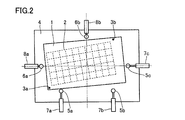
まず、処理対象材である基板1を準備する。基板1の表面には、パターン2およびアライメントマーク3a、3bが形成されている。パターン2は一例として格子状のパターンが形成されている。そして、図2に示すように、基準部材5a~5cおよび押圧部材6a、6bを、基板1の上部表面の中心部から十分後退させた状態で、チャックステージ4の上部表面上に基板1を配置する(工程(S10))。このとき、基板1の端部(端面)と基準部材5a~5cおよび押圧部材6a、6bとの間には間隔が形成された状態とすることが好ましい。
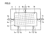
次に、図3に示すように、エアシリンダ8a、8bを動作させることにより、押圧部材6a、6bを基板1の端面に押付ける(工程(S20))。そして、この押圧部材6a、6bにより基板1を押して移動させることにより、基板1の基準部材5a~5cと対向する端部と当該基準部材5a~5cとを接触させる。なお、このとき基準部材5a~5cの位置は、図3のように基板1の端部が基準部材5a~5cと接触したときに基板1が所定の位置にくるように予め調整されていることが好ましい。また、エアシリンダ8a、8bが押圧部材6a、6bを介して基板1を押圧する圧力や速度は、基板1を破損しないように事前に調整しておくことが好ましい。当該調整は、たとえばエアシリンダ8a、8bへのエアの供給圧力を調整することにより実施できる。
次に、CCDカメラ10a、10b(図1参照)により、基板1の表面に形成されているアライメントマーク3a、3bを検出する(工程(S30))。このアライメントマーク3a、3bは、基板1の表面に形成されているパターンとの相対的な位置が予め決められている。そのため、このアライメントマーク3a、3bの位置に基づいて、基板1の表面に形成されているパターン2の位置を特定することができる。このアライメントマーク3a、3bの測定位置データは、CCDカメラ10a、10bから制御部20へ出力される。
そして、このアライメントマーク3a、3bの測定位置データにより特定される位置が、予め設定されている位置(すなわち基板1の表面に形成されたパターン2が、処理を受けるときに配置されるべき位置にある場合にアライメントマーク3a、3bが配置されるべき基準位置)になっているかどうかを制御部20において判別する(工程(S40))。具体的には、制御部において上記測定位置データと、予め決定されているアライメントマーク3a、3bの基準位置データとを対比する。
そして、この判別の結果アライメントマーク3a、3bの位置が予め決定されている基準位置からずれている場合には、そのずれが解消されるように電動シリンダ7a~7cを駆動することによって基準部材5a~5cの位置を変更する(工程(S50))。このとき、押圧部材6a、6bはエアシリンダ8a、8bにより基板1の端部に所定の力が押圧された状態を維持する。このように、基準部材5a~5cが移動することにより、基板1の位置は押圧部材6a、6bの押圧力によって基準部材5a~5cの動きに合わせて変化する。この結果、図4に示すように、アライメントマーク3a、3bの位置が予め定められた基準位置と重なるように、基板1は移動させられる。
そして、このように基板1が移動されることによってアライメントマーク3a、3bの位置が修正された後、再度上述した工程(S30)および工程(S40)を実施する。すなわち、CCDカメラ10a、10bによって当該アライメントマーク3a、3bの位置を測定し、得られた測定位置データを制御部20へ出力する。制御部20では、このアライメントマーク3a、3bの測定位置データにより特定される位置が、予め設定されている基準位置になっているかどうかを判別する。この工程(S40)において、アライメントマーク3a、3bの位置が基準位置になっていると判断された場合、基板1はチャックステージ4の表面に固定される(工程(S60))。
上記工程(S60)における基板1の固定方法としては任意の方法を用いることができるが、たとえば真空吸着法、あるいは静電吸着法などを用いることができる。一方、上述のようにCCDカメラ10a、10bにより検出されたアライメントマーク3a、3bの位置が予め定められた位置とずれている場合には、基板1のチャックステージ4への固定が解除されて再び上述した工程(S50)が実施される。このようなプロセスが、上記工程(S40)においてアライメントマーク3a、3bの位置が基準位置になっていると判断され、上記工程(S60)が実施されるまで繰返される。
このようにすれば、チャックステージ4自体をXYθステージなどを用いて移動させるといった後述するプロセスを用いる場合よりも、基板処理装置の構造を簡略化できるとともに当該基板処理装置のコストを低減できる。以下、上述したXYθステージを備える基板処理装置における基板の位置決め方法について、具体的に説明する。
図10~図14は、比較例としての基板処理装置における基板の位置決め方法を説明するための模式図である。図10~図14に示した基板処理装置は、基本的には図1に示した基板処理装置と同様の構造を備えるが、基準部材5a~5cがチャックステージ4の上部表面の所定の位置に固定された状態になっている。さらに、チャックステージ4は図示しないXYθステージにより移動可能となっている。
まず、図10に示すように、基準部材5a~5cおよび押圧部材6a、6bと接触しないように、基板1をチャックステージ4の上部表面上に搭載する。
次に、図11に示すように、エアシリンダ8a、8bを駆動させることにより、押圧部材6a、6bを基板1の端部に押付ける。この結果、基板1が移動され、基板1において基準部材5a~5cと対向する端部が当該基準部材5a~5cと接触した状態となる。このとき、基板1は、基準部材5a~5cにより規定されたチャックステージ4の上部表面上における所定の位置に位置決めされることになる。なお、基板1の表面に形成されたパターン2が、基板1の外周に対して予め設計された正しい位置に形成されていれば、基準部材5a~5cの位置を適切に設定することにより、パターン2およびアライメントマーク3a、3bが処理時に配置されるべき正しい位置へと配置された状態とできる筈である(図11参照)。
しかし、パターン2が基板1の表面において所定の位置からずれた位置へと形成されている場合(たとえば図12に示す基板1のパターン2参照)があり得る。このような場合における基板の位置決め方法を説明する。
まず、図12に示すように、図10に示したプロセスと同様に基板1をチャックステージ4の上部表面上に配置する。その後、図11に示した工程と同様の工程を実施することにより、図13に示すようにチャックステージ4の上部表面上の所定の位置に基板1を配置する。しかし、基板1の表面においてパターン2が所定の位置からずれて形成されているため、図13に示すパターン2の位置は、図11に示した場合と異なり、処理時に位置すべき領域からずれた状態になっている。
このため、この比較例としての基板処理装置においては、図13に示した状態でチャックステージ4に基板1を真空吸着などの任意の方法で吸着固定した後、CCDカメラによりアライメントマーク3a、3bの位置を検出する。そして、当該アライメントマーク3a、3bの位置が予め定められた基準位置(図11に示すアライメントマーク3a、3bの位置)からずれていることが検出されれば、当該アライメントマーク3a、3bの位置のずれが解消するように、基板1が搭載されたチャックステージ4自体をXYθステージを用いて水平面内(XY面内)において移動させる。この結果、図14に示すように、パターン2の位置を処理時の正しい位置へと修正できる。
このような比較例としての基板処理装置においては、パターン2の位置を正確な位置に位置決めするため、チャックステージ4自体を移動するためのXYθステージが必要となる。しかし、本発明による基板処理装置においては、図2~図4を用いて説明したように、基準部材5a~5cを可動な構成とすることにより比較例において説明したようなXYθステージを用いることなく基板1のパターン2を正確な位置へと位置決めすることができる。
なお、上述した本実施形態に従った基板処理装置におけるチャックステージ4の表面には、図5に示すように、基板1の移動をよりスムーズに行なうため、空気や不活性ガス(たとえば窒素ガスやアルゴンガスなど)といった気体を噴出する噴出口21が複数個形成されている。当該噴出口21には、図示しない配管が接続され、当該配管には上記気体の供給装置が、開閉弁を介して接続されている。この噴出口からは、上記工程(S50)においてたとえば圧縮空気を噴出することで、基板1をチャックステージ4の表面から浮かせることができる。この結果、工程(S50)において基板1をスムーズに移動させることができる。
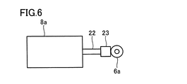
また、図6に示すように、押圧部材6aとエアシリンダ8aの駆動軸22との間に、弾性部材23を配置してもよい。このようにすれば、エアシリンダ8aのストローク端で当該押圧部材6aにより基板1を押圧する場合であっても、押圧部材6aを基板1の端部に接触させるときに、基板1の端部に加えられる過大な力を弾性部材23の変形により吸収することができる。このため、当該過大な力によって基板1が破損する可能性を低減できる。当該弾性部材23は、押圧部材6bとエアシリンダ8bの駆動軸との間に配置されていてもよい。弾性部材23としては、たとえばゴムやばねなどを用いることができる。
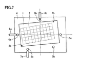
また、基板処理装置の構成によっては、基準部材5a~5cの一部のみを移動可能とすればよい場合も考えられる。たとえば、基板1を回転移動させることのみが必要である場合、図7~図9に示すように、複数の基準部材5a~5cのうちの一部のみ(図7~図9に示した例では基準部材5aのみ)を電動シリンダにより可動としてもよい。具体的には、図7~図9に示した基板処理装置では、基準部材5b、5cはチャックステージ4の上部表面上に固定される一方で、基準部材5aのみを電動シリンダ7aによって移動可能としている。この場合、以下のようにして基板1の表面に形成された基板1(より具体的にはパターン2)の位置決めを行なうことができる。以下、説明する。
まず、図7に示すように、基準部材5a~5cおよび押圧部材6a、6bと接触しない位置に基板1を配置する。この工程は基本的に図2に示した工程(S10)と同様である。
その後、エアシリンダ8a、8bを駆動させることにより、押圧部材6a、6bを基板1の端部に接触させる。この結果、押圧部材6a、6bによって基板1を移動させ、図8に示すように基準部材5a~5cに基板1の端部を接触させる。この工程は基本的に図3に示した工程(S20)と同様である。
この後、上述した工程(S30)~工程(S50)と同様の工程を実施する。すなわち、CCDカメラ10a、10b(図1参照)を用いて基板1の表面のアライメントマーク3a、3bの位置を検出する。そして、当該アライメントマーク3a、3bの位置が予め定められた基準位置とずれている場合には当該ずれを解消するように基板1を移動させる。この時、電動シリンダ7aを駆動させることにより基準部材5aの位置を変更する。この結果、基板1がチャックステージ4の上部表面上において当該上部表面に沿った面内で回転する。このようにして、図9に示すように基板1のパターン2が処理時の所定の位置へと位置決めされる。このようにしても、基板1のパターン2の位置決めを行なうことができる。
上述した基板処理装置では、基準部材5a~5cという3つの基準部材を配置しているが、当該基準部材の数は2つ(たとえば基準部材5aおよび基準部材5cという2つ)以上であれば、任意の数とすることができる。また、複数の基準部材について、すべてを可動としてもよいが、一部のみを電動シリンダ等に接続して可動とする一方、他の一部についてはチャックステージに固定してもよい。
また、上述した基板処理措置では、基準部材5a~5cを移動させるために電動シリンダ7a~7cを用いているが、他の移動部材(たとえばエアシリンダや油圧シリンダなど、任意の方式の直動ユニット)を用いることができる。さらに、押圧部材6a、6bを移動させるためにエアシリンダ8a、8bを用いているが、他の移動部材(たとえば電動シリンダや油圧シリンダなど、任意の方式の直動ユニット)を用いることができる。
ここで、上述した実施の形態と一部重複する部分もあるが、本発明の特徴的な構成を列挙する。
(1) この発明に従った基板処理装置は、基板1を搭載する搭載面(上部表面)を有する保持台(チャックステージ4)と、第1押圧部材(押圧部材6b)、第2押圧部材(押圧部材6a)、第1基準部材(基準部材5a)、第2基準部材(基準部材5c)、押圧部材移動部(エアシリンダ8a、8b)、第1基準部材移動部(電動シリンダ7a)を備える。第1押圧部材(6b)および第1基準部材(5a)は、保持台(チャックステージ4)に搭載された基板1を、搭載面に沿った第1の方向(図2の上下方向)から挟むように配置される。第2押圧部材(6a)および第2基準部材(5c)は、保持台(チャックステージ4)に搭載された上記基板1を、第1の方向と交差するとともに搭載面に沿う第2の方向(図2の左右方向)から挟むように配置される。押圧部材移動部(エアシリンダ8a、8b)は、第1押圧部材(6b)および前記第2押圧部材(6a)をそれぞれ第1基準部材(5a)側および第2基準部材(5c)側へ移動させる。第1基準部材移動部(電動シリンダ7a)は、第1基準部材(5a)を移動させる。
このようにすれば、第1基準部材(5a)を移動させることができるので、XYθステージなどを用いることなく、当該基板1が第1押圧部材(6b)と第1基準部材(5a)、および第2押圧部材(6a)と第2基準部材(5c)とによって挟まれることで位置決めされたときの当該基板1の位置を、高精度かつ大きな自由度で設定することができる。すなわち、高い位置決め精度を有する基板処理装置を、XYθステージなどを用いることなく低コストで実現できる。
ここで、図10~図14に示すように、基準部材5a~5cがチャックステージ4の搭載面(上部表面)において固定されている場合には、当該基準部材5a~5cの位置によって搭載面上での基板1の最終的な位置は決まる。一方、上述のように第1基準部材(5a)をチャックステージ4に対して可動とすることで、基板1において第1基準部材(5a)が接触する外周辺と搭載面の外周辺との為す角度を変更する(図4や図9に示すように基板1を搭載面に沿った方向に回転させる)といった操作が可能になる。
(2) 上記基板処理装置は、第2基準部材(5c)を移動させるための第2基準部材移動部(電動シリンダ7c)をさらに備えていてもよい。この場合、第2基準部材(5c)も保持台(チャックステージ4)に対して可動となるため、基板1の位置決め後の位置を決定する際の自由度をより大きくすることができる。
(3) 上記基板処理装置は、第1押圧部材(6b)と対向する第3基準部材(基準部材5b)をさらに備えていてもよい。この場合、第1基準部材(5a)とともに第3基準部材(5b)とも基板1の端部が接触した状態で基板1の位置決めを行なうことができるので、基板1の位置決め精度をより高めることができる。また、第1押圧部材(6b)を基板1に押しつけながら第1基準部材(5a)を移動させることで、第3基準部材(5b)と基板1との接触部を支点として基板1を回転させる、といった操作を容易に行なうことができる。
(4) 上記基板処理装置は、図1に示すように第3基準部材(5b)を移動させるための第3基準部材移動部(電動シリンダ7b)をさらに備えていてもよい。この場合、基板1の位置決め後の位置の選択の自由度をより大きくすることができる。
(5) 上記基板処理装置において、図7~図9に示すように、第3基準部材(5b)の位置は、保持台(チャックステージ4)に対して固定されていてもよい。この場合、基板処理装置の構成を過度に複雑化することなく、基板1の位置決め精度を高めることができる。
(6) 上記基板処理装置は、検出部(CCDカメラ10a、10b)と制御部20とをさらに備えていてもよい。検出部(CCDカメラ10a、10b)は、基板1の表面に形成されたアライメントマーク3a、3bの位置を検出する。制御部20は、検出部(10a、10b)から出力されたアライメントマーク3a、3bの測定位置データと、予め決定されているアライメントマーク3a、3bの基準位置データとに基づき、第1基準部材(5a)の移動量を決定する。この場合、アライメントマーク3a、3bの測定位置データに基づき、基板1の位置決めをより正確に行なうことができる。
(7) 上記基板処理装置において、押圧部材移動部(エアシリンダ8a、8b)は、第1押圧部材(6b)および第2押圧部材(6a)の移動速度および押圧力を調整可能になっていてもよい。この場合、第1押圧部材(6b)および第2押圧部材(6a)が基板1の端部と接触したことに起因して基板1が破損しないように、当該第1押圧部材(6b)および第2押圧部材(6a)の移動速度や基板1に対する押圧力を調整することができる。
(8) 上記基板処理装置は、図6に示すように、第1押圧部材(6b)および第2押圧部材(6a)の少なくともいずれか一方と押圧部材移動部(エアシリンダ8b、8a)との間に配置された弾性部材23をさらに備えていてもよい。この場合、第1押圧部材(6b)および第2押圧部材(6a)が基板1の端部と接触したことに起因して基板1が破損しないように、当該第1押圧部材(6b)および第2押圧部材(6a)が基板1に接触するときの衝撃などを弾性部材23により吸収することができる。
(9) 上記基板処理装置は、図5に示すように、保持台(チャックステージ4)の搭載面から基板1を浮上させた状態で基板1を保持するための補助部材(チャックステージ4の上部表面に形成された噴出口21および当該噴出口21に接続された配管と気体の供給装置など)をさらに備えていてもよい。この場合、搭載面上で基板1を移動させるときに、基板1表面と搭載面とが接触することで当該基板1表面に傷が発生することを防止できる。
(10) この発明に従った基板処理方法(基板1の位置決め方法)は、基板1を準備する工程と、当該基板1を保持台(チャックステージ4)の搭載面上に搭載する工程(S10)と、基板1の位置決めを行なう工程(工程(S20)~工程(S60))とを備える。基板1の位置決めを行なう工程では、搭載面上に搭載された基板1を、搭載面に沿った第1の方向から第1押圧部材(押圧部材6b)および第1基準部材(基準部材5a)により挟むとともに、第1の方向と交差するとともに搭載面に沿う第2の方向から第2押圧部材(押圧部材6a)および第2基準部材(基準部材5c)により挟むことにより上記基板1の位置決めを行なう。また、基板の位置決めを行なう工程は、第1押圧部材(6b)および第2押圧部材(6a)をそれぞれ第1基準部材(5a)側および第2基準部材(5c)側へ移動させる工程(S20)と、第1基準部材(5a)を移動させる工程(S50)とを含む。
このようにすれば、第1基準部材(5a)を移動させることができるので、XYθステージなどを用いることなく、当該基板1が第1押圧部材(6b)と第1基準部材(5a)、および第2押圧部材(6a)と第2基準部材(5c)によって挟まれることで位置決めされたときの当該基板1の位置を、高精度かつ大きな自由度で設定することができる。
(11) 上記基板処理方法において、基板1の位置決めを行なう工程(工程(S20)~工程(S60))は、第2基準部材(5c)を移動させる工程を含んでいてもよい。この場合、基板1の位置決め後の位置を決定する際の自由度をより大きくすることができる。
(12) 上記基板処理方法において、基板の位置決めを行なう工程(工程(S20)~工程(S60))では、第1押圧部材(6b)と対向する第3基準部材(基準部材5b)が、第1基準部材(5a)と同じ方向から基板1に接触してもよい。この場合、第1基準部材(5a)とともに第3基準部材(5b)とも基板1の端部が接触した状態で基板1の位置決めを行なうことができるので、基板1の位置決め精度をより高めることができる。また、第1押圧部材(6b)を基板1に押しつけながら第1基準部材(5a)を移動させることで、図4や図9などに示すように、第3基準部材(5b)と基板1との接触部を支点として基板1を回転させる、といった操作を容易に行なうことができる。すなわち、XYθステージなどを用いることなく、低コストかつ高い位置決め精度を実現できる基板処理方法を実現できる。
今回開示された実施の形態はすべての点で例示であって制限的なものではないと考えられるべきである。本発明の範囲は上記した説明ではなくて請求の範囲によって示され、請求の範囲と均等の意味および範囲内でのすべての変更が含まれることが意図される。
この発明は、基板の位置決めを行なうことが可能な基板処理装置および基板処理方法に特に有利に適用される。
1 基板、2 パターン、3a,3b アライメントマーク、4 チャックステージ、5a~5c 基準部材、6a,6b 押圧部材、7a~7c 電動シリンダ、8a,8b エアシリンダ、9a,9b レンズ、10a,10b CCDカメラ、20 制御部、21 噴出口、22 駆動軸、23 弾性部材。
Claims (6)
- 基板を搭載する搭載面を有する保持台と、
前記保持台に搭載された前記基板を、前記搭載面に沿った第1の方向から挟むように配置された第1押圧部材および第1基準部材と、
前記保持台に搭載された前記基板を、前記第1の方向と交差するとともに前記搭載面に沿う第2の方向から挟むように配置された第2押圧部材および第2基準部材と、
前記第1押圧部材および前記第2押圧部材をそれぞれ前記第1基準部材側および前記第2基準部材側へ移動させるための押圧部材移動部と、
前記第1基準部材を移動させるための第1基準部材移動部とを備える、基板処理装置。 - 前記基板の表面に形成されたアライメントマークの位置を検出する検出部と、
前記検出部から出力された前記アライメントマークの測定位置データと、予め決定されている前記アライメントマークの基準位置データとに基づき、前記第1基準部材の移動量を決定する制御部とを備える、請求項1に記載の基板処理装置。 - 前記保持台の前記搭載面から前記基板を浮上させた状態で前記基板を保持するための補助部材をさらに備える、請求項1または請求項2に記載の基板処理装置。
- 基板を準備する工程と、
前記基板を保持台の搭載面上に搭載する工程と、
前記搭載面上に搭載された前記基板を、前記搭載面に沿った第1の方向から第1押圧部材および第1基準部材により挟むとともに、前記第1の方向と交差するとともに前記搭載面に沿う第2の方向から第2押圧部材および第2基準部材により挟むことにより前記基板の位置決めを行なう工程とを備え、
前記基板の位置決めを行なう工程は、
前記第1押圧部材および前記第2押圧部材をそれぞれ前記第1基準部材側および前記第2基準部材側へ移動させる工程と、
前記第1基準部材を移動させる工程とを含む、基板処理方法。 - 前記基板の位置決めを行なう工程は、前記第2基準部材を移動させる工程を含む、請求項4に記載の基板処理方法。
- 前記基板の位置決めを行なう工程では、前記第1押圧部材と対向する第3基準部材が、前記第1基準部材と同じ方向から前記基板に接触する、請求項4または請求項5に記載の基板処理方法。
Applications Claiming Priority (2)
| Application Number | Priority Date | Filing Date | Title |
|---|---|---|---|
| JP2013-258185 | 2013-12-13 | ||
| JP2013258185A JP2015115528A (ja) | 2013-12-13 | 2013-12-13 | 基板処理装置および基板処理方法 |
Publications (1)
| Publication Number | Publication Date |
|---|---|
| WO2015087897A1 true WO2015087897A1 (ja) | 2015-06-18 |
Family
ID=53371199
Family Applications (1)
| Application Number | Title | Priority Date | Filing Date |
|---|---|---|---|
| PCT/JP2014/082635 Ceased WO2015087897A1 (ja) | 2013-12-13 | 2014-12-10 | 基板処理装置および基板処理方法 |
Country Status (2)
| Country | Link |
|---|---|
| JP (1) | JP2015115528A (ja) |
| WO (1) | WO2015087897A1 (ja) |
Cited By (1)
| Publication number | Priority date | Publication date | Assignee | Title |
|---|---|---|---|---|
| CN110696408B (zh) * | 2019-08-29 | 2021-07-13 | 晟光科技股份有限公司 | 一种工控lcd显示面板的压合装置 |
Families Citing this family (4)
| Publication number | Priority date | Publication date | Assignee | Title |
|---|---|---|---|---|
| JP7157587B2 (ja) * | 2018-08-08 | 2022-10-20 | キヤノン株式会社 | 保持装置、リソグラフィ装置及び物品の製造方法 |
| JP7259476B2 (ja) * | 2019-03-27 | 2023-04-18 | 東京エレクトロン株式会社 | アライメント装置、基板処理装置、アライメント方法及び基板処理方法 |
| KR102822419B1 (ko) * | 2020-12-08 | 2025-06-18 | 에스케이하이닉스 주식회사 | 반도체 제조 장치, 이를 이용하는 캐리어 위치 판독 방법 및 반도체 다이의 부착 방법 |
| JP7854356B2 (ja) * | 2022-07-13 | 2026-05-01 | キヤノン株式会社 | 位置決め装置、リソグラフィ装置、および物品製造方法 |
Citations (6)
| Publication number | Priority date | Publication date | Assignee | Title |
|---|---|---|---|---|
| JP2004241465A (ja) * | 2003-02-04 | 2004-08-26 | Ckd Corp | ワークの位置修正装置及びカセットの搬送装置 |
| JP2004286484A (ja) * | 2003-03-19 | 2004-10-14 | Olympus Corp | 基板位置決め装置 |
| JP2005085881A (ja) * | 2003-09-05 | 2005-03-31 | Dainippon Screen Mfg Co Ltd | 基板処理装置および基板処理方法 |
| JP2005116878A (ja) * | 2003-10-09 | 2005-04-28 | Toshiba Corp | 基板支持方法および基板支持装置 |
| JP2005353811A (ja) * | 2004-06-10 | 2005-12-22 | Dainippon Printing Co Ltd | 載置装置、載置台 |
| JP2011035021A (ja) * | 2009-07-30 | 2011-02-17 | Tokyo Electron Ltd | 基板位置合わせ機構、それを用いた真空予備室および基板処理システム |
-
2013
- 2013-12-13 JP JP2013258185A patent/JP2015115528A/ja active Pending
-
2014
- 2014-12-10 WO PCT/JP2014/082635 patent/WO2015087897A1/ja not_active Ceased
Patent Citations (6)
| Publication number | Priority date | Publication date | Assignee | Title |
|---|---|---|---|---|
| JP2004241465A (ja) * | 2003-02-04 | 2004-08-26 | Ckd Corp | ワークの位置修正装置及びカセットの搬送装置 |
| JP2004286484A (ja) * | 2003-03-19 | 2004-10-14 | Olympus Corp | 基板位置決め装置 |
| JP2005085881A (ja) * | 2003-09-05 | 2005-03-31 | Dainippon Screen Mfg Co Ltd | 基板処理装置および基板処理方法 |
| JP2005116878A (ja) * | 2003-10-09 | 2005-04-28 | Toshiba Corp | 基板支持方法および基板支持装置 |
| JP2005353811A (ja) * | 2004-06-10 | 2005-12-22 | Dainippon Printing Co Ltd | 載置装置、載置台 |
| JP2011035021A (ja) * | 2009-07-30 | 2011-02-17 | Tokyo Electron Ltd | 基板位置合わせ機構、それを用いた真空予備室および基板処理システム |
Cited By (1)
| Publication number | Priority date | Publication date | Assignee | Title |
|---|---|---|---|---|
| CN110696408B (zh) * | 2019-08-29 | 2021-07-13 | 晟光科技股份有限公司 | 一种工控lcd显示面板的压合装置 |
Also Published As
| Publication number | Publication date |
|---|---|
| JP2015115528A (ja) | 2015-06-22 |
Similar Documents
| Publication | Publication Date | Title |
|---|---|---|
| CN104028944B (zh) | 整形装置及其定位机构 | |
| JP6078298B2 (ja) | 位置補正機能を有する作業装置および作業方法 | |
| WO2015087897A1 (ja) | 基板処理装置および基板処理方法 | |
| TWI472493B (zh) | The breaking device of the brittle material substrate | |
| JP5551482B2 (ja) | 基板貼り合わせ装置及び貼り合わせ基板の製造方法 | |
| US20090029627A1 (en) | Polishing apparatus and polishing method | |
| WO2010137320A1 (ja) | アライメントステージ | |
| KR20190029697A (ko) | 본딩 정렬을 위한 디바이스 및 방법 | |
| KR101394312B1 (ko) | 웨이퍼 정렬장치 | |
| CN101859036B (zh) | 基板贴合装置和基板贴合方法 | |
| WO2008069203A1 (ja) | 基板処理装置および基板処理方法 | |
| CN121374137B (zh) | 一种硅基面板邦定方法 | |
| KR100509281B1 (ko) | 평판디스플레이의 이방전도성필름 및 구동칩 본딩장치 | |
| KR102665610B1 (ko) | 얼라인먼트 장치, 성막 장치, 얼라인먼트 방법, 성막 방법, 및 전자 디바이스의 제조 방법 | |
| JP2013205764A (ja) | 露光装置 | |
| KR20190121556A (ko) | 디스플레이 패널 상에 필름을 부착하기 위한 장치 | |
| JP5171230B2 (ja) | アライメントマークの検出装置及び方法 | |
| JP2008171873A (ja) | 位置決め装置、位置決め方法、加工装置及び加工方法 | |
| JP2013229447A (ja) | 転写装置および物品製造方法 | |
| KR20110027573A (ko) | 도포 장치와 그 도포 위치 보정 방법 | |
| JP5047772B2 (ja) | 実装基板製造方法 | |
| JP4654829B2 (ja) | 部品実装状態検査装置及び方法 | |
| JP5878821B2 (ja) | パターン形成装置 | |
| TW201401395A (zh) | 電子零件之安裝裝置及安裝方法 | |
| KR101367852B1 (ko) | 기판에 식각 영역을 만들기 위한 장치 및 방법 |
Legal Events
| Date | Code | Title | Description |
|---|---|---|---|
| 121 | Ep: the epo has been informed by wipo that ep was designated in this application |
Ref document number: 14869399 Country of ref document: EP Kind code of ref document: A1 |
|
| NENP | Non-entry into the national phase |
Ref country code: DE |
|
| 122 | Ep: pct application non-entry in european phase |
Ref document number: 14869399 Country of ref document: EP Kind code of ref document: A1 |