WO2015087785A1 - 眼科装置 - Google Patents
眼科装置 Download PDFInfo
- Publication number
- WO2015087785A1 WO2015087785A1 PCT/JP2014/082161 JP2014082161W WO2015087785A1 WO 2015087785 A1 WO2015087785 A1 WO 2015087785A1 JP 2014082161 W JP2014082161 W JP 2014082161W WO 2015087785 A1 WO2015087785 A1 WO 2015087785A1
- Authority
- WO
- WIPO (PCT)
- Prior art keywords
- eye
- spot image
- bright spot
- optical system
- image
- Prior art date
- Legal status (The legal status is an assumption and is not a legal conclusion. Google has not performed a legal analysis and makes no representation as to the accuracy of the status listed.)
- Ceased
Links
Images





Classifications
-
- A—HUMAN NECESSITIES
- A61—MEDICAL OR VETERINARY SCIENCE; HYGIENE
- A61B—DIAGNOSIS; SURGERY; IDENTIFICATION
- A61B3/00—Apparatus for testing the eyes; Instruments for examining the eyes
- A61B3/10—Objective types, i.e. instruments for examining the eyes independent of the patients' perceptions or reactions
- A61B3/13—Ophthalmic microscopes
-
- A—HUMAN NECESSITIES
- A61—MEDICAL OR VETERINARY SCIENCE; HYGIENE
- A61B—DIAGNOSIS; SURGERY; IDENTIFICATION
- A61B3/00—Apparatus for testing the eyes; Instruments for examining the eyes
- A61B3/10—Objective types, i.e. instruments for examining the eyes independent of the patients' perceptions or reactions
- A61B3/103—Objective types, i.e. instruments for examining the eyes independent of the patients' perceptions or reactions for determining refraction, e.g. refractometers, skiascopes
-
- A—HUMAN NECESSITIES
- A61—MEDICAL OR VETERINARY SCIENCE; HYGIENE
- A61B—DIAGNOSIS; SURGERY; IDENTIFICATION
- A61B3/00—Apparatus for testing the eyes; Instruments for examining the eyes
- A61B3/10—Objective types, i.e. instruments for examining the eyes independent of the patients' perceptions or reactions
- A61B3/107—Objective types, i.e. instruments for examining the eyes independent of the patients' perceptions or reactions for determining the shape or measuring the curvature of the cornea
-
- A—HUMAN NECESSITIES
- A61—MEDICAL OR VETERINARY SCIENCE; HYGIENE
- A61B—DIAGNOSIS; SURGERY; IDENTIFICATION
- A61B3/00—Apparatus for testing the eyes; Instruments for examining the eyes
- A61B3/10—Objective types, i.e. instruments for examining the eyes independent of the patients' perceptions or reactions
- A61B3/14—Arrangements specially adapted for eye photography
- A61B3/15—Arrangements specially adapted for eye photography with means for aligning, spacing or blocking spurious reflection ; with means for relaxing
- A61B3/152—Arrangements specially adapted for eye photography with means for aligning, spacing or blocking spurious reflection ; with means for relaxing for aligning
-
- A—HUMAN NECESSITIES
- A61—MEDICAL OR VETERINARY SCIENCE; HYGIENE
- A61B—DIAGNOSIS; SURGERY; IDENTIFICATION
- A61B3/00—Apparatus for testing the eyes; Instruments for examining the eyes
- A61B3/10—Objective types, i.e. instruments for examining the eyes independent of the patients' perceptions or reactions
- A61B3/16—Objective types, i.e. instruments for examining the eyes independent of the patients' perceptions or reactions for measuring intraocular pressure, e.g. tonometers
- A61B3/165—Non-contacting tonometers
Definitions
- the present invention relates to an ophthalmologic apparatus that performs alignment in a direction orthogonal to the optical axis by projecting alignment index light onto an eye to be examined to form a bright spot image.
- an ophthalmic apparatus that automatically aligns an eye to be examined has been proposed (see, for example, Patent Document 1) before performing measurement with a mounted measurement unit.
- the eye is irradiated with alignment index light to form a bright spot image by reflection from the cornea, and an image of the test eye on which the bright spot image is formed is acquired to obtain a bright spot in the test eye.
- alignment can be easily performed with high accuracy regardless of a difference in skill of the examiner.
- the present invention has been made in view of the above circumstances, and an object thereof is to provide an ophthalmologic apparatus capable of appropriately performing alignment on an eye to be examined in which an intraocular lens is inserted.
- the ophthalmologic apparatus is an ophthalmologic apparatus including an eye characteristic measuring unit that measures an eye characteristic of the eye to be examined, and the eye characteristic measuring unit for the eye to be examined.
- a driving unit for moving the eye, and a control unit for controlling the eye characteristic measuring unit and the driving unit, wherein the eye characteristic measuring unit irradiates the eye to be examined with alignment index light to thereby cornea the eye to be examined.
- a corneal reflection luminescent spot image by reflection from the eye, and having a luminescent spot image acquisition optical system for acquiring an image of the eye to be examined on which the corneal reflection luminescent spot image is formed, and the control unit includes the bright spot A front side bright spot image formed on the front side of the cornea reflection bright spot image or a rear side bright spot formed on the rear side of the cornea reflection bright spot image by irradiating the alignment index light to the image acquisition optical system.
- Luminance value in the image of the eye to be examined as a point image An intraocular lens that moves the eye characteristic measurement unit with the position of the corneal reflection luminescent spot image in the image of the subject eye acquired by the luminescent spot image acquisition optical system as a target while performing luminescent spot image dimming control to be reduced It has an alignment mode.
- the ophthalmologic apparatus of the present invention it is possible to appropriately align the eye to be examined into which the intraocular lens is inserted.
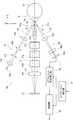
- FIG. 3 is an explanatory diagram for explaining an optical configuration of an intraocular pressure measurement unit 20 of the ophthalmologic apparatus 10.
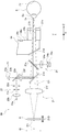
- FIG. 3 is an explanatory diagram viewed from a direction different from FIG. 2 for describing an optical configuration of an intraocular pressure measurement unit 20 of the ophthalmologic apparatus 10.
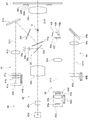
- 4 is an explanatory diagram for explaining an optical configuration of an eye characteristic measurement unit 40 of the ophthalmologic apparatus 10.
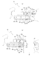
- FIG. It is explanatory drawing for demonstrating a mode that the apparatus main body part 13 is moved and a measurement mode is switched.
- FIG. It is explanatory drawing for demonstrating the predetermined height position HL and the predetermined front position FL using the positional relationship of the apparatus main-body part 13 and the forehead holding
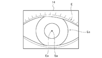
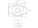
- FIG. It is explanatory drawing which shows a mode that the corneal reflection bright spot image Sa is formed when XY alignment index light Ra irradiates the eye E to be examined. It is explanatory drawing which shows the image of the anterior eye part image of the to-be-tested eye E in which the corneal reflection bright spot image Sa was formed.
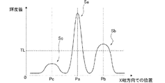
- FIG. 13 is a graph showing a state in which the light amount of the light source for XY alignment 22a is lowered with respect to the eye Ei having the light amount distribution shown in FIG. 12, where the vertical axis indicates the luminance value and the horizontal axis indicates the position in the X-axis direction. Is shown.
- FIG. 13 is a graph showing a state in which the in-focus position is shifted to the rear bright spot image Sc side with respect to the eye Ei having the light amount distribution shown in FIG. 12, the vertical axis indicating the luminance value, and the horizontal axis indicating the X axis. The position in the direction is shown. It is a flowchart which shows the alignment mode switching process (alignment mode switching method) performed in the control part 33.
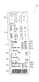
- FIG. It is explanatory drawing which shows the output result 52 printed out.
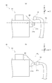
- FIGS. 5A shows a state in which the intraocular pressure measurement mode is set
- FIG. 5B shows a state in which the eye characteristic measurement mode is set.
- FIG. 6 (a) shows a predetermined height position HL
- the ophthalmologic apparatus 10 includes an intraocular pressure measurement unit 20 that measures the intraocular pressure of an eye E (see FIG. 2 and the like) as an example of an eye characteristic measurement unit, and other optical characteristics of the eye E. It is a composite type ophthalmologic apparatus provided with the eye characteristic measurement part 40 which measures (eye characteristic).
- FIGS. 2 and 3 show a fundus (retina) Ef, a cornea (anterior eye portion) Ec, and a corneal apex Ea.
- the ophthalmologic apparatus 10 is configured by providing a base 11 with an apparatus main body 13 via a drive unit 12.
- the apparatus main body 13 is provided with an intraocular pressure measurement unit 20 and an eye characteristic measurement unit 40 on the inner side, and with a display unit 14, a chin rest 15 and a forehead support unit 16 on the outer side.
- the display unit 14 is formed of a liquid crystal display, and displays an image such as an anterior segment image of the eye E, a test result, and the like under the control of a control unit 33 (see FIG. 2) described later.
- the display unit 14 has a touch panel function, and moves the apparatus main body 13 by an operation for performing measurement using the intraocular pressure measurement unit 20 or the eye characteristic measurement unit 40 or manually. It is possible to perform an operation for this.
- the display unit 14 displays a switching icon in each measurement mode to be described later using the function of the touch panel, and enables the switching operation of each measurement mode by touching the switching icon.
- the operation for performing the measurement may be performed by providing a measurement switch and operating the measurement switch.
- an operation for moving the apparatus main body 13 may be performed by providing a control lever or a movement operation switch and operating the control lever or the movement operation switch.
- the chin rest 15 and the forehead support 16 fix the face of the subject (patient), that is, the position of the eye E to be measured with respect to the apparatus main body 13, and are fixed to the base 11. ing.
- the chin receiving portion 15 is a place where the subject places his chin
- the forehead holding portion 16 is a place where the subject places the forehead.
- the display unit 14, the chin rest 15 and the forehead support 16 are provided on both sides of the apparatus main body 13, and the display unit 14 is inspected during normal use.
- the chin rest 15 and the forehead support 16 are on the subject side.
- the display unit 14 is rotatably supported by the apparatus main body unit 13 to change the orientation of the display surface, for example, to direct the display surface toward the subject, or to display the display surface sideways (X-axis). Direction).
- the apparatus main body 13 moves with respect to the base 11 by the drive unit 12, that is, moves with respect to the eye E (face of the subject) fixed by the jaw holder 15 and the forehead support 16. It is possible to do.
- the drive unit 12 is perpendicular to the vertical direction (Y-axis direction) and the front-rear direction (Z-axis direction (left-right direction when FIG. 1 is viewed from the front)) of the apparatus main body 13 with respect to the base 11.
- the upper side in the vertical direction is the positive side in the Y-axis direction
- the subject side in the front-rear direction 1 is the positive side in the Z-axis direction
- the front side in FIG. 1 is the front side in the X-axis direction (see the arrow in FIG. 1).
- the drive part 12 has the Y-axis drive part 12a, the Z-axis drive part 12b, and the X-axis drive part 12c.
- the Y-axis drive portion 12a is provided on the base 11, and moves the apparatus main body 13 in the Y-axis direction (vertical direction) with respect to the base 11 via the Z-axis drive portion 12b and the X-axis drive portion 12c. (Displace).
- the Y-axis drive portion 12a is a location for moving the apparatus main body 13 in the Y-axis direction (vertical direction) in the drive unit 12.
- the Y-axis drive portion 12a has a support column 12d and a Y-axis moving frame 12e.
- the support column 12d is fixed to the base 11 and extends from the base 11 in the Y-axis direction.
- the Y-axis moving frame 12e has a frame shape that can surround the support column 12d, and can be moved relative to the Y-axis direction via a Y-axis guide member (not shown). Is attached.
- the Y-axis moving frame 12e has a range that can move in the Y-axis direction with respect to the support column 12d (base 11) so that the intraocular pressure measurement unit 20 is the most in an intraocular pressure measurement mode (see FIG. 5A) described later. It is possible to position the eye characteristic measurement unit 40 in the lower side (negative side) and to position the eye characteristic measurement unit 40 in the uppermost side (positive side) in an eye characteristic measurement mode (see FIG. 5B) described later. Is set to
- an elastic member is provided between the Y-axis moving frame 12e and the support column 12d, and a pressing force is applied upward from the elastic member.
- the elastic member is formed of a spiral wire, and uses a tension spring that contracts most in an unloaded state and exhibits an elastic force that resists the operation of separating one end and the other end. . That is, the Y-axis moving frame 12e is configured to be suspended from the support column 12d by an elastic member.
- the Y-axis moving frame 12e is supported on the support column 12d (base 11) via an elastic member in a state where the relative movement direction with respect to the support column 12d (base 11) is defined by the Y-axis guide member in the Y-axis direction. Has been. If the elastic member supports the Y-axis moving frame 12e by applying a pressing force to the support column 12d (base 11) in the Y-axis direction to the Y-axis moving frame 12e, a compression spring is used. It may be used or may have other configurations, and is not limited to this embodiment.
- the compression spring is constituted by a spiral wire, and exhibits the elastic force that opposes the operation of bringing the one end and the other end close to each other by extending most in an unloaded state.
- the support column 12d or the base 11 may be configured to support the Y-axis moving frame 12e from below via the compression spring.
- the Y-axis driving portion 12a is provided with a driving force transmission mechanism that applies a moving force that moves the Y-axis moving frame 12e in the Y-axis direction with respect to the support column 12d.
- a driving force transmission mechanism that applies a moving force that moves the Y-axis moving frame 12e in the Y-axis direction with respect to the support column 12d.
- an upward movement force is applied from the drive force transmission mechanism to the Y-axis movement frame 12e, thereby moving the Y-axis movement frame 12e from the position where the elastic member is balanced to the Y axis direction positive side.
- the Y-axis moving frame 12e is moved from the position where the elastic members are balanced to the Y-axis direction negative side.
- the Z-axis drive portion 12b is provided on the Y-axis moving frame 12e (Y-axis drive portion 12a). Move (displace) in the Z-axis direction (front-rear direction).
- the Z-axis drive portion 12 b is a location for moving the apparatus main body 13 in the Z-axis direction (front-rear direction) in the drive unit 12.
- the Z-axis drive portion 12b has a Z-axis support base 12f and a Z-axis movement base 12g.
- the Z-axis support 12f is fixed to the Y-axis moving frame 12e and is moved in the Y-axis direction together with the Y-axis moving frame 12e.
- the Z-axis support base 12f supports the Z-axis movement base 12g through a Z-axis guide member (not shown) so as to be capable of relative movement in the Z-axis direction.
- the Z-axis drive portion 12b is provided with a drive force transmission mechanism that applies a moving force that moves the Z-axis moving base 12g in the Z-axis direction with respect to the Z-axis support base 12f.
- the Z-axis moving table 12g is appropriately moved in the Z-axis direction by applying a moving force in the Z-axis direction to the Z-axis moving table 12g from the driving force transmission mechanism.
- the X-axis drive portion 12c is provided on the Z-axis moving base 12g (Z-axis drive portion 12b), and the apparatus body 13 is moved in the X-axis direction (left-right direction) with respect to the Z-axis drive portion 12b, that is, the base 11. Move (displace).
- the X-axis drive portion 12 c is configured to move the apparatus main body 13 in the X-axis direction (left-right direction) in the drive unit 12.
- the X-axis drive portion 12c has an X-axis support base 12h and an X-axis movement base 12i.
- the X-axis support base 12h is fixed to the Z-axis movement base 12g and is moved in the Z-axis direction together with the Z-axis movement base 12g.
- the X-axis support base 12h supports the X-axis movement base 12i through an X-axis guide member (not shown) so that relative movement in the X-axis direction is possible.
- the X-axis drive portion 12c is provided with a drive force transmission mechanism that applies a moving force that moves the X-axis moving base 12i in the X-axis direction with respect to the X-axis support base 12h.
- the X-axis moving table 12i is appropriately moved in the X-axis direction by applying a moving force in the X-axis direction to the X-axis moving table 12i from the driving force transmission mechanism.
- the X-axis moving base 12i is provided with an apparatus main body 13 through an attachment board (not shown) to which an intraocular pressure measurement unit 20 and an eye characteristic measurement unit 40 provided on the inside of the apparatus main body 13 are attached. Is fixed.
- the drive unit 12 appropriately drives the Y-axis drive part 12a, the Z-axis drive part 12b, and the X-axis drive part 12c, thereby moving the apparatus main body part 13 in the vertical direction (Y-axis direction) relative to the base 11. , And can be appropriately moved in the front-rear direction (Z-axis direction) and the left-right direction (X-axis direction).
- the Y-axis drive part 12a, the Z-axis drive part 12b, and the X-axis drive part 12c are connected to the control unit 33 (see FIG. 2), respectively. Are driven under the control of the control unit 33.
- the control unit 33 constitutes an electric control system in the ophthalmologic apparatus 10 and comprehensively controls each unit of the ophthalmologic apparatus 10 by a program stored in a built-in storage unit.
- the ophthalmic apparatus 10 is provided with a cover member that forms the overall outer shape, from the base 11 to the apparatus main body 13 through the drive unit 12. Is covered by the cover member.
- the Y-axis drive portion 12a, the Z-axis drive portion 12b, and the X-axis drive portion 12c are shown stacked in the Y-axis direction, but are completely divided in the Y-axis direction.
- the components are configured to overlap each other when viewed in a direction orthogonal to the Y-axis direction.
- the drive unit 12 that is, the ophthalmologic apparatus 10 it is possible to appropriately move the apparatus main body 13 with respect to the base 11 while preventing an increase in the height dimension (size as viewed in the Y-axis direction). Has been.
- the device main body 13 is provided with an intraocular pressure measurement unit 20 and an eye characteristic measurement unit 40 inward.
- the intraocular pressure measurement unit 20 is used when measuring the intraocular pressure of the eye E.
- the eye characteristic measuring unit 40 measures the optical characteristic (eye characteristic) of the eye E, and in this embodiment, the shape of the cornea Ec of the eye E and the eye refractive power (spherical power, astigmatism) of the eye E. Frequency, astigmatic axis angle, etc.).
- an optical axis O ⁇ b> 1 as an example of a main optical axis of an intraocular pressure measurement unit, which will be described later, which is the main optical axis in the intraocular pressure measurement unit 20, is used in FIG. 5 (see FIG. 5).
- the intraocular pressure measurement unit 20 is basically provided above the eye characteristic measurement unit 40 in the apparatus main body unit 13.
- the intraocular pressure measurement unit 20 and the ocular characteristic measurement unit 40 are separately configured.
- the intraocular pressure measurement unit 20 and the ocular characteristic measurement unit 40 include a part of the intraocular pressure measurement unit 20 and the ocular characteristic measurement unit 40 by crossing a part of one optical system with the other optical system. This is because they are assembled into an integrated structure.
- the intraocular pressure measuring unit 20 is a non-contact type tonometer. As shown in FIGS. 2 and 3, the intraocular pressure measurement unit 20 includes an anterior ocular segment observation optical system 21 that constitutes a part of an exemplary bright spot image acquisition optical system and an exemplary bright spot image acquisition optical system. An XY alignment index projection optical system 22, a fixation target projection optical system 23, an applanation detection optical system 24, a Z alignment index projection optical system 25, and a Z alignment detection optical system 26 are included.
- the anterior segment observation optical system 21 is provided for observing the anterior segment of the eye E and XY alignment (alignment in the direction along the XY plane).
- the anterior ocular segment observation optical system 21 is provided with an anterior ocular segment illumination light source 21a (see FIG. 2), an airflow spray nozzle 21b, an anterior ocular window glass 21c (see FIG. 3), and a chamber on the optical axis O1.
- a window glass 21d, a half mirror 21e, a half mirror 21g, an objective lens 21f, and a CCD camera 21i as an example of an imaging device are provided.
- the anterior segment illumination light source 21a is positioned around the anterior segment window glass 21c (see FIG. 2), and a plurality (only two are shown in FIG.
- the airflow spray nozzle 21b is a nozzle for spraying an airflow onto the eye E (anterior eye portion), and is provided in an air compression chamber 34a (see FIG. 3) of the airflow spray mechanism 34 described later.
- the CCD camera 21i generates an image signal based on an image (anterior eye image or the like) formed on the light receiving surface, and outputs the generated image signal to the control unit 33 (see FIG. 2).
- the image acquired by the CCD camera 21i is appropriately displayed on the display unit 14 (see FIG. 1) under the control of the control unit 33, and is appropriately output to an external device (not shown).
- the CCD camera 21i is movable along the optical axis O1 by a focusing drive mechanism 21D.
- the focusing drive mechanism 21D appropriately moves the CCD camera 21i to focus on the anterior eye part (cornea Ec) of the eye E under the control of the control unit 33 (see FIG. 2).
- the drive source is shared with a fixation target moving mechanism 41D (see FIG. 4) of the fixation target projection optical system 41 described later. That is, the drive source drives the focusing drive mechanism 21D in an intraocular pressure measurement mode (see FIG. 5A) described later, and is fixed in an eye characteristic measurement mode (see FIG. 5B) described later.
- the target moving mechanism 41D is driven.
- the control unit 33 changes the position of the CCD camera 21i on the optical axis O1 in accordance with the position of the intraocular pressure measurement unit 20, that is, the apparatus main body unit 13, via the focusing drive mechanism 21D, thereby changing the eye E to be examined. Focus on the anterior segment of the eye (cornea Ec).
- the control unit 33 displaces the CCD camera 21i via the focusing drive mechanism 21D at least at two positions of the first focal position f1 and the second focal position f2 on the optical axis O1.
- the first focal position f1 is the anterior segment of the eye E when the intraocular pressure measurement unit 20 (device main body unit 13) is set to a position that enables measurement of the intraocular pressure of the eye E.
- the position is in focus near (cornea Ec).
- the position where the measurement of the intraocular pressure of the eye E can be performed is set to a position where the distance (distance d1) from the tip of the airflow spray nozzle 21b to the eye E is 11 mm. (See FIG. 5A).
- the second focal position f2 corresponds to the anterior eye portion (cornea Ec) of the eye E when the intraocular pressure measurement unit 20 (apparatus body 13) is positioned sufficiently away from the eye E (subject). It is the position where the focus is in the vicinity.
- the intraocular pressure measurement unit 20 when switching from the eye characteristic measurement mode (measurement mode by the eye characteristic measurement unit 40) to the intraocular pressure measurement mode (measurement mode by the intraocular pressure measurement unit 20), the intraocular pressure measurement unit 20 (device)
- the main body 13) is first moved in the Y-axis direction to a height position corresponding to the eye E, and then moved in the Z-axis direction to approach the eye E.
- the intraocular pressure measurement unit 20 (device main body unit 13) is first retracted from the position where one of the intraocular pressures is measured. (Z-axis direction negative side), moving in the left-right direction (X-axis direction), and performing the alignment while moving in the direction approaching the other eye E to be examined. Such an operation is performed to prevent the tip of the airflow spray nozzle 21b of the tonometry part 20 from accidentally contacting the subject (its nose, etc.).
- the control unit 33 is positioned in the Z-axis direction (front-rear direction) of the apparatus main body 13 (intraocular pressure measurement unit 20) with respect to the base 11, that is, the drive unit 12 (its Z-axis drive portion 12b).
- the position of the CCD camera 21i is switched between the first focal position f1 and the second focal position f2 according to the control position. This is because the interval between the intraocular pressure measurement unit 20 and the eye E to be examined is roughly determined by the position of the apparatus main body 13 (intraocular pressure measurement unit 20) with respect to the base 11.
- the drive source is shared with the fixation target moving mechanism 41D (see FIG. 4) of the fixation target projection optical system 41 described later.
- the index moving mechanism 43D (see FIG. 4) of the index projection optical system 43 (light receiving optical system 44) may be shared with the drive source, and is not limited to the present embodiment.
- an anterior ocular segment image of the subject eye E is illuminated by a CCD camera 21i while illuminating the subject eye E (the anterior segment) with an anterior segment illumination light source 21a (see FIG. 2). get.
- the anterior eye part image (the light beam) passes through the airflow blowing nozzle 21b and passes through the anterior eye part window glass 21c (including a glass plate 34b described later), the chamber window glass 21d, the half mirror 21g, and the half mirror 21e. Then, it is focused by the objective lens 21f and formed on the CCD camera 21i (its light receiving surface).
- the CCD camera 21i (anterior ocular segment observation optical system 21) outputs a signal based on reception of the formed anterior ocular segment image to the control unit 33 (see FIG. 2).
- the control unit 33 causes the display unit 14 (see FIG. 1) to appropriately display the anterior segment image acquired by the CCD camera 21i (anterior segment observation optical system 21).
- the CCD camera 21 i functions as an image pickup device that acquires an anterior segment image of the eye E in the anterior segment observation optical system 21.
- the imaging element may be a CMOS as long as it acquires an anterior segment image of the eye E and outputs the signal to the control unit 33, and is limited to the present embodiment. It is not something.
- the reflected light from the cornea Ec of the XY alignment index light projected onto the eye E by the XY alignment index projection optical system 22 is converted into a CCD camera 21i (its light receiving surface).
- the reflected light flux passes through the inside of the airflow blowing nozzle 21b, passes through the chamber window glass 21d, the half mirror 21g, and the half mirror 21e, and reaches the objective lens 21f.
- the reflected light beam is converged by the objective lens 21f and advanced to the CCD camera 21i.
- a bright spot image is formed at a position corresponding to the positional relationship in the XY direction between the apparatus main body 13 (intraocular pressure measurement unit 20) and the cornea Ec.
- the CCD camera 21i anterior ocular segment observation optical system 21
- the bright spot image of the XY alignment index light is formed on the cornea Ec of the eye E to be examined.
- control part 33 can acquire the image (the data) of the anterior eye part (cornea Ec) in which the bright spot image was formed, and the anterior eye part (in which the bright spot image was formed on the display part 14)
- An image of the cornea Ec can be displayed as appropriate.
- the display unit 14 also displays an alignment auxiliary mark generated by image generation means (not shown) in an overlapping manner.
- the XY alignment index projection optical system 22 projects the index light onto the cornea Ec of the eye E from the front.
- the index light is used to adjust the position of the eye E to be examined (its anterior eye portion (cornea Ec)) with respect to the intraocular pressure measuring unit 20 viewed in a direction along the XY plane (hereinafter also referred to as XY direction), so-called XY. It has a function that enables alignment in the direction.
- the index light also has a function of enabling detection of the deformation amount (degree of deformation (applanation)) of the cornea Ec of the eye E.
- the XY alignment index projection optical system 22 includes an XY alignment light source 22a, a condenser lens 22b, an aperture stop 22c, a pinhole plate 22d, a dichroic mirror 22e, and a projection lens 22f as an example of an alignment light source.
- the eye observation optical system 21 and the half mirror 21e are shared.
- the XY alignment light source 22a is a light source that emits infrared light.
- the projection lens 22f is disposed on the optical path of the XY alignment index projection optical system 22 so that the focal point coincides with the pinhole plate 22d.
- infrared light emitted from the XY alignment light source 22a passes through the aperture stop 22c while being focused by the condenser lens 22b, and reaches the pinhole plate 22d (its hole). And proceed.
- the light beam that has passed through the pinhole plate 22d (its hole) is reflected by the dichroic mirror 22e and travels to the projection lens 22f, and the progressed infrared light is projected by the projection lens 22f. It advances to the half mirror 21e as a parallel light beam.
- the parallel light beam is advanced on the optical axis O ⁇ b> 1 of the anterior ocular segment observation optical system 21 by being reflected by the half mirror 21 e.
- the parallel luminous flux passes through the half mirror 21g and the chamber window glass 21d, proceeds to the inside of the airflow spray nozzle 21b, and passes through the airflow spray nozzle 21b to the eye E as XY alignment index light. It reaches.
- the XY alignment index light is reflected on the surface of the cornea Ec so as to form a bright spot image (see reference symbol Sa in FIG. 7) at an intermediate position between the cornea vertex Ea of the cornea Ec and the center of curvature of the cornea Ec. .
- the aperture stop 22c is provided at a position conjugate with the corneal vertex Ea of the cornea Ec with respect to the projection lens 22f.
- the fixation target projection optical system 23 projects (presents) the fixation target onto the eye E to be examined.
- the fixation target projection optical system 23 includes a fixation target light source 23a and a pinhole plate 23b.
- the fixation target projection optical system 23 shares the XY alignment index projection optical system 22, the dichroic mirror 22e, and the projection lens 22f, and anterior ocular segment observation optics.
- the system 21 and the half mirror 21e are shared.
- the fixation target light source 23a is a light source that emits visible light. In the fixation target projection optical system 23, the fixation target light emitted from the fixation target light source 23a is advanced to the pinhole plate 23b (the hole) and passes through the pinhole plate 23b (the hole).
- the fixation target light (the light beam) is made substantially parallel light by the projection lens 22f, travels to the half mirror 21e, and is reflected by the half mirror 21e, whereby the optical axis O1 of the anterior ocular segment observation optical system 21 is obtained. Go on top.
- the luminous flux passes through the half mirror 21g and the chamber window glass 21d, travels into the airflow spray nozzle 21b, passes through the airflow spray nozzle 21b, and reaches the eye E to be examined.
- the fixation target projection optical system 23 fixes the line of sight of the subject by causing the subject to gaze at the fixation target projected onto the eye E as a fixation target.
- the applanation detection optical system 24 receives light reflected by the cornea Ec of the XY alignment index light projected onto the eye E by the XY alignment index projection optical system 22, and the surface of the cornea Ec. The amount of deformation (applanation) is detected.
- the applanation detection optical system 24 includes a lens 24a, a pinhole plate 24b, a sensor 24c, and a half mirror 21g provided on the optical path of the anterior ocular segment observation optical system 21.
- the lens 24a collects the light reflected by the cornea Ec of the XY alignment index light in the central hole of the pinhole plate 24b.
- the pinhole plate 24b is provided with the central hole positioned at the above-described condensing position by the lens 24a.
- the sensor 24c is a light receiving sensor capable of detecting the amount of light, and outputs a signal corresponding to the amount of received light. In the present embodiment, a photodiode is used.
- the sensor 24c (applanation detection optical system 24) outputs a signal corresponding to the received light amount to the control unit 33.
- the reflected light beam of the XY alignment index light reflected by the surface (corneal surface) of the cornea Ec of the eye E passes through the air blowing nozzle 21b, passes through the chamber window glass 21d, and passes through the half mirror 21g.
- a part thereof is reflected by the half mirror 21g, travels to the lens 24a, converges by the lens 24a, and travels to the pinhole plate 24b.
- the surface of the cornea Ec is deformed and gradually flattened by the airflow spraying mechanism 34 (see FIG. 1 and the like), which will be described later, blowing airflow from the airflow spraying nozzle 21b toward the cornea Ec. It will be in a state.
- the applanation detection optical system 24 when the surface of the cornea Ec is flattened according to the setting described above, the entire reflected light beam that has traveled reaches the sensor 24c through the hole of the pinhole plate 24b, and other states Then, the sensor reaches the sensor 24c while being partially blocked by the pinhole plate 24b. For this reason, the applanation detection optical system 24 can detect that the surface of the cornea Ec has been flattened (applanation) by detecting the time when the amount of light received by the sensor 24c becomes maximum.
- the applanation detection optical system 24 can detect the shape (applanation) of the surface of the cornea Ec that has been deformed by spraying fluid, and the sensor 24c can detect the reflected light (reflected light) from the cornea Ec for the detection. It functions as a light receiving portion that receives a light beam.
- the Z alignment index projection optical system 25 projects the alignment index light (alignment index parallel light beam) in the Z-axis direction obliquely onto the cornea Ec of the eye E to be examined.
- the Z alignment index projection optical system 25 includes a Z alignment light source 25a, a condenser lens 25b, an aperture stop 25c, a pinhole plate 25d, and a projection lens 25e on the optical axis O2.
- the light source 25a for Z alignment is a light source that emits infrared light (for example, wavelength 860 nm).
- the aperture stop 25c is provided at a position conjugate with the corneal vertex Ea of the cornea Ec with respect to the projection lens 25e.
- the projection lens 25e is disposed with its focal point coincident with the pinhole plate 25d (the hole).
- infrared light (its light beam) emitted from the Z alignment light source 25a is condensed by the condenser lens 25b, passes through the aperture stop 25c, and proceeds to the pinhole plate 25d.
- the light beam that has passed through the pinhole plate 25d (the hole) is advanced to the projection lens 25e, and is advanced to the cornea Ec as parallel light by the projection lens 25e.
- the infrared light (the light beam (Z alignment index light)) is reflected on the surface of the cornea Ec so as to form a bright spot image located inside the eye E.
- the Z alignment detection optical system 26 receives the reflected light from the cornea Ec of the Z alignment index light from a direction symmetric with respect to the optical axis O1 of the anterior ocular segment observation optical system 21, and the apparatus main body 13 (intraocular pressure measurement). Part 20) and the cornea Ec in the Z-axis direction are detected.
- the Z alignment detection optical system 26 includes an imaging lens 26a, a cylindrical lens 26b, and a sensor 26c on the optical axis O3.
- the cylindrical lens 26b has power in the Y-axis direction.
- the sensor 26c is a light receiving sensor that can detect a light receiving position on the light receiving surface, and can be configured using a line sensor or PSD (Position Sensitive Detector). In this embodiment, a line sensor is used.
- the sensor 26 c is connected to the Z alignment detection correction unit 32.
- the reflected light beam projected from the alignment index light by the Z alignment index projection optical system 25 and reflected from the surface of the cornea Ec proceeds to the imaging lens 26a.
- the reflected light beam is converged by the imaging lens 26a, travels to the cylindrical lens 26b, and is condensed in the Y-axis direction by the cylindrical lens 26b to form a bright spot image on the sensor 26c.
- This sensor 26c has a conjugate positional relationship with respect to the above-described bright spot image formed on the inside of the eye E by the Z alignment index projection optical system 25 and the imaging lens 26a in the XZ plane, and is Y ⁇ .
- the corneal apex Ea is in a conjugate positional relationship with the imaging lens 26a and the cylindrical lens 26b. That is, the sensor 26c has a conjugate relationship with the aperture stop 25c (the magnification at this time is set so that the image of the aperture stop 25c is smaller than the size of the sensor 26c), and the cornea Ec has shifted in the Y-axis direction. However, the reflected light beam on the surface of the cornea Ec efficiently enters the sensor 26c.
- the sensor 26 c (Z alignment detection optical system 26) outputs a signal based on reception of the formed bright spot image to the Z alignment detection correction unit 32.
- the airflow spray mechanism 34 has an air compression chamber 34a, and is provided with an air compression drive unit 34d (see FIG. 1).
- the air compression drive unit 34d has a piston that can move inward of the air compression chamber 34a and a drive unit that moves the piston.
- the device main body unit 13 includes an intraocular pressure measurement unit. 20 (its optical system) is provided above.
- the air compression drive unit 34d is driven under the control of the control unit 33 (see FIG. 2) to compress the air in the air compression chamber 34a.
- An air blowing nozzle 21b is attached to the air compression chamber 34a via a transparent glass plate 34b, and a chamber window glass 21d is provided to face the nozzle.
- the air compression chamber 34a is prevented from interfering with the above-described function in the anterior ocular segment observation optical system 21.
- the air compression chamber 34a is provided with a pressure sensor 34c that detects the pressure of the air compression chamber 34a.
- the pressure sensor 34c is connected to the control unit 33 (see FIG. 2), and outputs a signal corresponding to the detected pressure to the control unit 33.
- the air compression driving unit 34 d compresses the air in the air compression chamber 34 a under the control of the control unit 33, so that the airflow is directed from the airflow blowing nozzle 21 b toward the cornea Ec of the eye E to be examined. Can be sprayed.
- the pressure when the airflow is blown from the airflow blowing nozzle 21b can be acquired by detecting the pressure in the air compression chamber 34a with the pressure sensor 34c.
- a change in pressure with respect to time may be set as a predetermined characteristic in the airflow to be blown.
- the intraocular pressure measurement unit 20 includes a driver (drive mechanism) for performing lighting control of the anterior segment illumination light source 21a, the XY alignment light source 22a, the fixation target light source 23a, and the Z alignment light source 25a.
- a controller 33 (see FIG. 2) is connected to the driver. Therefore, the intraocular pressure measurement unit 20 appropriately turns on the anterior segment illumination light source 21a, the XY alignment light source 22a, the fixation target light source 23a, and the Z alignment light source 25a under the control of the control unit 33.
- the CCD camera 21i is appropriately moved on the optical axis O1 via the focusing drive mechanism 21D under the control of the control unit 33, and output from the CCD camera 21i. An image generation process based on the image signal is performed, and the generated image is appropriately displayed on the display unit 14.
- the power switch of the ophthalmic apparatus 10 is turned on, and an operation for performing measurement using the intraocular pressure measurement unit 20 is performed on the display unit 14.
- the intraocular pressure measurement unit 20 enters the intraocular pressure measurement mode (see FIG. 5A) as described later, and then the anterior ocular segment illumination light source 21a, the XY alignment light source 22a, and the fixation target light source 23a.
- the Z alignment light source 25a is appropriately turned on.
- the intraocular pressure measurement unit 20 may repeatedly blink each of the light sources 21a, 23a, and 25a at different periods, and may identify which light source is the light.
- the intraocular pressure measurement unit 20 lights the fixation target light source 23 a of the fixation target projection optical system 23, thereby projecting the fixation target onto the eye E to be examined.
- the subject's line of sight is fixed.
- the intraocular pressure measurement unit 20 lights the XY alignment light source 22a of the XY alignment index projection optical system 22 to project a parallel light beam onto the cornea Ec.
- the reflected light beam reflected by the cornea Ec is received by the CCD camera 21 i of the anterior ocular segment observation optical system 21 and the sensor 24 c of the applanation detection optical system 24. Further, as shown in FIG.
- the intraocular pressure measurement unit 20 lights the Z alignment light source 25 a of the Z alignment index projection optical system 25 to project a parallel light beam for alignment in the Z-axis direction onto the cornea Ec. .
- the reflected light beam reflected by the cornea Ec is received by the sensor 26 c of the Z alignment detection optical system 26.
- the anterior segment illumination light source 21a of the anterior segment observation optical system 21 is turned on to illuminate the anterior segment of the subject eye E, and the anterior segment image of the subject eye E is displayed as a CCD camera. An image is formed on 21i.
- the intraocular pressure measurement unit 20 displays the anterior eye image of the eye E on which the luminescent spot image of the XY alignment index light is formed and the alignment auxiliary mark on the display unit 14 although they are not clearly shown. Let The examiner operates the operation unit displayed on the display unit 14 while looking at the display unit 14, thereby moving the apparatus main body unit 13 up and down and left and right so that the bright spot image appears in the screen of the display unit 14. Align so that.
- the Z alignment detection / correction unit 32 is based on the light reception signal of the sensor 26 c of the Z alignment detection optical system 26 and the calculation result of the XY alignment detection unit 31, and the apparatus main body unit 13 and the cornea Ec. Is calculated in the Z-axis direction.
- the drive unit 12 is controlled based on the position in the XY direction obtained from the anterior segment observation optical system 21 and the calculation result output from the Z alignment detection correction unit 32 under the control of the control unit 33.
- the apparatus body 13 is moved in the vertical direction (Y-axis direction) and the front-rear direction (Z-axis direction) with respect to the base 11. ) And the right and left direction (X-axis direction) as appropriate, and auto alignment (automatic alignment adjustment) is performed.
- the control unit 33 operates the airflow spray mechanism 34 to spray an airflow from the airflow spray nozzle 21b toward the cornea Ec of the eye E to be examined. Then, in the eye E, the surface of the cornea Ec is deformed and gradually becomes flat (applanation). In the process in which the cornea Ec is gradually flattened (applanation), the amount of light received by the sensor 24c of the applanation detection optical system 24 becomes maximum when the surface of the cornea Ec is flattened (applanation). . Therefore, in the intraocular pressure measurement unit 20, the control unit 33 determines that the surface of the cornea Ec is flat (applanation) based on the change in the amount of light received by the sensor 24c.
- the applanation detection optical system 24 (sensor 24c) can detect the applanation of the cornea Ec.
- the control unit 33 obtains the intraocular pressure of the eye E (calculates the intraocular pressure value) based on the output from the pressure sensor 34c (the pressure of the blown airflow) and calculates the intraocular pressure. The result is displayed on the display unit 14.
- control part 33 based on the time from the time of detecting that the surface of the cornea Ec was made flat (applanation) from the time of starting the blowing of the airflow by the airflow blowing nozzle 21b (airflow blowing mechanism 34), What calculates
- the eye characteristic measurement unit 40 measures the shape of the cornea Ec of the eye E and the eye refractive power (spherical power, astigmatism power, astigmatic axis angle, etc.) of the eye E.
- the eye characteristic measuring unit 40 includes a fixation target projection optical system 41, an observation optical system 42, an eye refractive power measurement ring-shaped index projection optical system 43, a light receiving optical system 44, and an alignment light projection system 45.
- the fixation target projection optical system 41 projects the target on the fundus oculi Ef (see FIGS. 2 and 3) of the eye E to fixate and cloud the eye E to be examined.
- the observation optical system 42 observes the anterior eye part (cornea Ec) of the eye E to be examined.
- the ring-shaped index projection optical system 43 for measuring eye refractive power projects a pattern light beam as a ring-shaped index for measuring eye refractive power onto the fundus oculi Ef of the eye E to measure the eye refractive power of the eye E.
- the light receiving optical system 44 causes the imaging element 44d described later to receive the eye refractive power measurement ring-shaped index image reflected from the fundus oculi Ef of the eye E.
- the alignment light projection system 45 projects the index light toward the eye E in order to detect the alignment state in the XY direction.
- the optical system of the eye characteristic measuring unit 40 is provided with a working distance detection optical system for detecting a working distance between the eye E to be examined and the apparatus main body 13 although not shown.
- the fixation target projection optical system 41 includes a fixation target light source 41a, a collimator lens 41b, an index plate 41c, a relay lens 41d, a mirror 41e, a dichroic mirror 41f, a dichroic mirror 41g, and an objective lens 41h on the optical axis O11. .
- the index plate 41c is provided with a target for fixing the eye E to be inspected and fogged.
- the fixation target light source 41a, the collimator lens 41b, and the index plate 41c constitute a fixation target unit 41U, and the fixation target projection optical system 41 is fixed by the fixation target moving mechanism 41D so as to fixate and cloud the eye E to be examined. It is possible to move integrally along the optical axis O11. Note that the positions where the dichroic mirror 41g and the objective lens 41h are provided are on the main optical axis O10 in the eye characteristic measurement unit 40 described later.
- this fixation target projection optical system 41 visible light is emitted from a fixation target light source 41a, and the visible light is converted into a parallel light beam by a collimator lens 41b, and then transmitted through an index plate 41c to be a target light beam.
- the target light beam is reflected by the mirror 41e after passing through the relay lens 41d, passes through the dichroic mirror 41f, and advances to the dichroic mirror 41g.
- the target light flux is reflected by the dichroic mirror 41g onto the main optical axis O10 in the eye characteristic measuring unit 40, and is advanced to the eye E through the objective lens 41h.
- the fixation target projection optical system 41 fixes the line of sight of the subject by causing the subject to focus on the target luminous flux (fixation target) projected onto the eye E as a fixation target. Further, the fixation target projection optical system 41 moves the fixation target unit 41U from a state in which the subject gazes as a fixation target to a position where the focus is not achieved, so that the eye E is in a cloudy state. .
- the observation optical system 42 includes an illumination light source (not shown), and includes a half mirror 42a, a relay lens 42b, an imaging lens 42c, and an image sensor 42d on the main optical axis O10.
- the objective lens 41h and the dichroic mirror 41g are shared.
- the image sensor 42d is a two-dimensional solid-state image sensor, and a CMOS image sensor is used in this embodiment.
- the anterior eye part (cornea Ec) of the eye E is illuminated with the illumination light beam emitted from the illumination light source, and the illumination light beam reflected by the anterior eye part is acquired by the objective lens 41h.
- the reflected illumination light beam is imaged on the imaging element 42d (its light receiving surface) by the imaging lens 42c through the objective lens 41h, through the dichroic mirror 41g and the half mirror 42a, through the relay lens 42b.
- the imaging element 42d outputs an image signal based on the acquired image to the control unit 33 (see FIG. 2).
- the control unit 33 causes the display unit 14 to display an image of the anterior segment (cornea Ec) based on the input image signal.
- an image of the anterior segment (cornea Ec) can be formed on the image sensor 42d (its light receiving surface), and the image of the anterior segment can be displayed on the display unit 14. it can.
- the illumination light source of the observation optical system 42 is turned off when the refractive power is measured after the alignment is completed.
- the eye refractive power measurement ring index projection optical system 43 includes an eye refractive power measurement light source 43a, a lens 43b, a conical prism 43c, a ring index plate 43d, a lens 43e, a bandpass filter 43f, a pupil ring 43g, and a perforated prism 43h. And the fixed prism projection optical system 41, the dichroic mirror 41f, the dichroic mirror 41g, and the objective lens 41h.
- the eye refractive power measurement light source 43a and the pupil ring 43g are arranged at an optically conjugate position, and the ring index plate 43d and the fundus oculi Ef of the eye E are arranged at an optically conjugate position.
- the eye refractive power measurement light source 43a, the lens 43b, the conical prism 43c, and the ring index plate 43d constitute an index unit 43U.
- the index unit 43U projects an eye refractive power measurement ring index by the index moving mechanism 43D.
- the optical system 43 can be moved integrally along the optical axis O13.
- the light beam emitted from the light source 43a for measuring eye refractive power is converted into a parallel light beam by the lens 43b and travels to the ring index plate 43d through the conical prism 43c.
- the luminous flux passes through the ring-shaped pattern portion formed on the ring index plate 43d and becomes a pattern luminous flux as a ring-shaped index for eye refractive power measurement.
- the pattern light flux is advanced to the perforated prism 43h through the lens 43e, the band pass filter 43f and the pupil ring 43g, and is reflected by the reflecting surface of the perforated prism 43h.
- the pattern light beam is reflected by the dichroic mirror 41g after being reflected by the dichroic mirror 41f, so as to travel on the main optical axis O10 in the eye characteristic measuring unit 40.
- the pattern light beam is imaged on the fundus oculi Ef (see FIGS. 2 and 3) of the eye E by the objective lens 41h.
- the ring-shaped index projection optical system 43 for measuring eye refractive power is provided with ring-shaped index projection light sources 46A, 46B, 46C for measuring the corneal shape on the front side of the objective lens 41h.
- the corneal shape measurement ring-shaped index projection light sources 46A, 46B, and 46C are concentrically provided with respect to the main optical axis O10 at a predetermined distance from the eye E (cornea Ec) on the ring pattern 47.
- a ring-shaped index light for corneal shape measurement is projected onto the optometry E (cornea Ec).
- the corneal shape measurement ring-shaped index light is projected onto the cornea Ec of the eye E, thereby forming a corneal shape measurement ring-shaped index light on the cornea Ec.
- the ring-shaped index for measuring the corneal shape (the light beam) is reflected on the cornea Ec of the eye E to be imaged on the image sensor 42d by the observation optical system 42 described above. Therefore, in the observation optical system 42, the display unit 14 can display an image (image) of a ring-shaped index for corneal shape measurement so as to overlap the image of the anterior segment (cornea Ec).
- the light receiving optical system 44 includes a hole 44a of the perforated prism 43h, a mirror 44b, a lens 44c, and an imaging device 44d, and shares the fixation target projection optical system 41, the objective lens 41h, the dichroic mirror 41g, and the dichroic mirror 41f.
- the ring-shaped index projection optical system 43 for measuring eye refractive power and the rotary prism 43i are shared.
- the image pickup device 44d is a two-dimensional solid-state image pickup device, and a CCD (charge coupled device) image sensor is used in this embodiment.
- This image sensor 44d is linked to the index unit 43U of the eye refractive power measurement ring-shaped index projection optical system 43 by the index moving mechanism 43D of the eye refractive power measurement ring-shaped index projection optical system 43, and receives the light receiving optical system. It is possible to move along 44 optical axes O14.
- a pattern reflected light beam guided to the fundus oculi Ef (see FIGS. 2 and 3) by the eye refractive power measurement ring-shaped index projection optical system 43 and reflected by the fundus oculi Ef is reflected by the objective lens 41h.
- the light is condensed, reflected by the dichroic mirror 41g, then reflected by the dichroic mirror 41f, and advanced to the rotary prism 43i.
- the reflected pattern reflected light beam travels through the rotary prism 43i to the hole 44a of the holed prism 43h and passes through the hole 44a.
- the pattern reflected light beam that has passed through the hole 44a is reflected by the mirror 44b, and a pattern reflected light beam, that is, a ring-shaped index for eye refractive power measurement is formed on the image pickup device 44d (its light receiving surface) by the lens 44c.
- the imaging element 44d outputs an image signal based on the acquired image to the control unit 33 (see FIG. 2).
- the control unit 33 causes the display unit 14 (see FIG. 1) to display an image of an eye refractive power measurement ring index based on the input image signal.
- an image of a ring-shaped index for measuring eye refractive power can be formed on the image sensor 44d (its light-receiving surface), and the ring-shaped index for measuring eye refractive power is displayed on the display unit 14. An image can be displayed.
- the alignment light projection system 45 includes an LED 45a, a pinhole 45b, and a lens 45c, shares the observation optical system 42 and the half mirror 42a, and shares the fixation target projection optical system 41, the dichroic mirror 41g, and the objective lens 41h. .
- the light beam from the LED 45a is converted into an alignment index light beam through the pinhole 45b (the hole) and reflected by the half mirror 42a through the lens 45c, so that the main optical axis in the eye characteristic measurement unit 40 is obtained.
- Advance over O10 In the alignment light projection system 45, the alignment index light beam is advanced to the objective lens 41h through the dichroic mirror 41g, and is projected as an alignment index light beam toward the cornea Ec of the eye E through the objective lens 41h.
- the alignment light projection system 45 has a function of automatically aligning the apparatus main body 13 with respect to the eye E by projecting an alignment index light beam toward the cornea Ec of the eye E.
- the alignment index light beam projected as parallel light toward the eye E is reflected by the cornea Ec of the eye E, and a bright spot image as an alignment index image is projected on the image sensor 42d by the observation optical system 42.
- This bright spot image is positioned within an alignment mark formed by an optical system (not shown), the alignment is completed.
- the eye characteristic measurement unit 40 controls lighting of the fixation target light source 41a, the illumination light source of the observation optical system 42, the eye refractive power measurement light source 43a, the LED 45a, and the corneal shape measurement ring-shaped index projection light sources 46A, 46B, and 46C.
- a control unit 33 (see FIG. 2) is connected to the driver. Therefore, the eye characteristic measurement unit 40, under the control of the control unit 33, projects the fixation target light source 41a, the illumination light source of the observation optical system 42, the eye refractive power measurement light source 43a, the LED 45a, and the corneal shape measurement ring-shaped index projection.
- the light sources 46A, 46B, and 46C are appropriately turned on.
- the eye characteristic measurement unit 40 moves the fixation target unit 41U integrally along the optical axis O11 via the fixation target moving mechanism 41D under the control of the control unit 33, and moves the index.
- the index unit 43U is moved integrally along the optical axis O13 via the mechanism 43D, and the imaging element 44d is moved along the optical axis O14.
- the eye characteristic measurement unit 40 performs an image generation process based on the image signals output from the image sensor 42d and the image sensor 44d under the control of the control unit 33, and the generated image is displayed. Displayed appropriately on the display unit 14.
- the illumination light source is turned on in the observation optical system 42, and the anterior eye part is displayed on the display unit 14.
- An image of (cornea Ec) is displayed.
- the examiner operates the operation unit displayed on the display unit 14 so that the pupil of the eye E is positioned within the screen of the display unit 14, thereby moving the apparatus main body unit 13 up, down, left, and right. Schematic alignment of the apparatus main body 13 with respect to the eye E is performed.
- the eye characteristic measurement unit 40 (control unit 33) can detect the pupil from the image of the anterior segment based on the image signal output from the image sensor 42d.
- the detection of the pupil can be performed, for example, by storing in advance the shape to be recognized as the pupil in the anterior eye image and detecting the shape to be recognized based on the contrast in the image. Therefore, in the eye characteristic measurement unit 40, for example, when the subject eye E to be measured is switched between left and right, the pupil is formed based on the image while moving the apparatus main body 13 in the left-right direction according to the switching. By detecting, the above-described general alignment can be automatically performed.
- the observation optical system 42 causes the display unit 14 to display a bright spot image as an alignment index image.
- the eye characteristic measurement unit 40 starts alignment detection based on the alignment light projection system 45 and the working distance detection optical system (not shown). That is, in the eye characteristic measuring unit 40, the apparatus main body 13 is moved in the vertical direction (Y-axis direction) and the front-rear direction (Z-axis) with respect to the base 11 so that the bright spot image as the alignment index image is positioned in the alignment mark. Direction) and left and right direction (X-axis direction) as appropriate, and auto alignment (automatic alignment adjustment) is performed. Thereby, in the eye characteristic measurement part 40, the automatic alignment with respect to the vertex of the cornea Ec of the eye E of the apparatus main body part 13 is completed.
- the eye characteristic measuring unit 40 turns on the corneal shape measurement ring-shaped index projection light sources 46A, 46B, and 46C of the eye-refractive-index ring-shaped index projection optical system 43, and uses the corneal shape measurement ring-shaped index as the cornea. Project to Ec.
- the control unit 33 measures the shape of the cornea Ec from the image of the corneal shape measurement ring-shaped index projected onto the cornea Ec based on the image displayed on the display unit 14 (image signal from the imaging element 42d). To do. Since the details of the measurement of the shape of the cornea Ec are known, the description thereof is omitted.
- the control unit 33 can measure the spherical power, the cylindrical power, and the shaft angle as the eye refractive power by a known method.
- the configuration of the eye refractive power measurement unit is the same as that disclosed in Japanese Patent Application Laid-Open No. 2002-253506, but is not limited to this configuration.
- the control unit 33 performs measurement of the corneal shape and measurement of eye refractive power (optical characteristics).
- the control part 33 stores a calculation result etc. in a memory
- storage part (illustration omitted) suitably.
- the tonometry part 20 is basically provided above the eye characteristic measurement part 40, and the tonometry part 20 and the eye characteristic measurement part 40 are provided. It is attached to the mounting base and fixed to each other.
- the intraocular pressure measurement unit 20 and the eye characteristic measurement unit 40 are integrated to eliminate the need to change the positional relationship.
- the mounting base that is, the intraocular pressure measurement unit 20 and the eye characteristic measurement unit 40 (device main body unit 13) attached thereto, are connected to the drive unit 12, that is, the Y-axis drive part 12a, the Z-axis drive part 12b, and the X-axis drive part 12c. Accordingly, the base 11 is appropriately moved in the vertical direction (Y-axis direction), the front-rear direction (Z-axis direction), and the left-right direction (X-axis direction).
- the apparatus main body 13 is moved with respect to the base 11 by the drive unit 12 (Y-axis drive part 12 a, Z-axis drive part 12 b and X-axis drive part 12 c).
- Each of the intraocular pressure measurement unit 20 and the eye characteristic measurement unit 40 can be moved to a position corresponding to the eye E (face of the subject) fixed by the chin rest 15 and the forehead support 16. (See FIG. 5).
- the intraocular pressure measurement is performed by moving the apparatus main body 13 (mounting base) in the vertical direction (Y-axis direction) with respect to the base 11 by the Y-axis drive portion 12a of the drive unit 12.
- the eye E can be positioned on the extension of the optical axis O1 of the anterior ocular segment observation optical system 21 of the unit 20 so that the tonometry part 20 can correspond to the height position of the eye E (FIG. 5 ( a)).
- the anterior eye of the intraocular pressure measuring unit 20 is moved in the front-rear direction (Z-axis direction) by the Z-axis drive portion 12 b of the drive unit 12.
- the tip of the airflow spray nozzle 21b of the partial observation optical system 21 is located at a predetermined distance (interval d1) from the eye E (the corneal vertex Ea).
- the distance d1 is 11 mm in this embodiment.
- This state is a measurement mode by the intraocular pressure measurement unit 20, that is, an intraocular pressure measurement mode.
- the apparatus main body part 13 (mounting base) is moved in the vertical direction (Y-axis direction) by the Y-axis drive part 12 a of the drive part 12 with respect to the base 11, so The eye E can be positioned on the extended line of the main optical axis O10 of 40, and the eye characteristic measuring unit 40 can correspond to the height position of the eye E (see FIG. 5B).
- the ophthalmologic apparatus 10 as shown in FIG.5 (b), it is moved to the front-back direction (Z-axis direction) by the Z-axis drive part 12b of the drive part 12, and the front end ( In this embodiment, the ring pattern 47) is located at a predetermined distance (interval d2) from the eye E.
- the front end of the eye characteristic measuring unit 40 refers to a structure that is closest to the subject in the eye characteristic measuring unit 40, and is a ring pattern 47 in this embodiment.
- the distance d2 is about 80 mm in this embodiment.
- This state is a measurement mode by the eye characteristic measurement unit 40, that is, an eye characteristic measurement mode.
- the apparatus main body 13 is provided with a height position detection unit 48 that detects that a predetermined height position HL has been reached.
- the height position HL is set from the viewpoint of preventing the airflow blowing nozzle 21b of the intraocular pressure measurement unit 20 from interfering with the forehead portion 16.
- the height position HL is set to have a sufficiently large distance between the airflow spray nozzle 21b and the forehead portion 16, but the distance may be set as appropriate.
- the present invention is not limited to this embodiment.
- the height position detector 48 outputs a signal indicating that to the controller 33 (see FIG. 2).
- the control unit 33 acquires the signal from the height position detection unit 48, the control unit 33 is in the intraocular pressure measurement mode, or when the intraocular pressure measurement unit 20 is on the positive side in the Z-axis direction (the subject) If it exists on the side), the movement of the apparatus main body 13 upward is stopped.
- the predetermined front and rear positions are set from the viewpoint of preventing the airflow blowing nozzle 21b from interfering with the forehead portion 16 when viewed in the Z-axis direction.
- the apparatus main body 13 is provided with a front position detection unit 49 that detects that a predetermined front position FL has been reached.
- the front position FL is set from the viewpoint of preventing the airflow spray nozzle 21b of the intraocular pressure measurement unit 20 from interfering with the forehead portion 16 in the eye characteristic measurement mode.
- the front position FL is a position where the distance between the tip of the airflow spray nozzle 21b and the forehead portion 16 is 1 mm.
- the forward position FL may be set as appropriate by setting the distance between the airflow spray nozzle 21b and the forehead portion 16 and is not limited to this embodiment.
- the front position detection unit 49 When the apparatus main body 13 reaches the front position FL, the front position detection unit 49 outputs a signal indicating that to the control unit 33 (see FIG. 2).
- the control unit 33 acquires the signal from the front position detection unit 49 in the eye characteristic measurement mode, the control unit 33 moves the apparatus main body unit 13 forward (Z-axis direction positive side (subject side)). Stop that.
- this ophthalmologic apparatus 10 In this ophthalmologic apparatus 10, generally, after measuring the shape of the cornea Ec of the eye E and the eye refractive power (spherical power, astigmatism power, astigmatic axis angle, etc.) of the eye E by the eye characteristic measuring unit 40, The intraocular pressure of the eye E is measured by the intraocular pressure measurement unit 20.
- the control unit 33 controls the operation of each unit based on the operation performed on the display unit 14.
- the ophthalmologic apparatus 10 displays an intraocular pressure switching icon for the intraocular pressure measurement mode and an ocular characteristic switching icon for the eye characteristic measurement mode on the display unit 14.
- the display unit 14 if it is possible to select and switch between the intraocular pressure measurement mode and the ocular characteristic measurement mode, instead of displaying the intraocular pressure switching icon and the ocular characteristic measurement mode, the display unit 14
- the switch icon may be displayed, or an icon in another format may be displayed, and is not limited to the configuration of the present embodiment.
- the eye characteristic measuring unit 40 in order to measure the shape of the cornea Ec of the eye E and the eye refractive power (spherical power, astigmatism power, astigmatic axis angle, etc.) of the eye E first by the eye characteristic measuring unit 40, the eye characteristics of the display unit 14 are measured. It is assumed that the switching icon is touched (selected).
- the Y-axis drive portion 12a, the Z-axis drive portion 12b, and the X-axis drive portion 12c of the drive unit 12 are appropriately driven to enter an eye characteristic measurement mode (see FIG. 5B). . That is, in the ophthalmologic apparatus 10, as shown in FIG. 5B, the eye E is positioned on the extension line of the main optical axis O10 of the eye characteristic measurement unit 40, and the fixation target projection of the eye characteristic measurement unit 40 is displayed. Assuming that the objective lens 41h of the optical system 41 is located at a predetermined distance (interval d2) from the eye E, the eye characteristic measuring unit 40 is made to correspond to the eye E.
- the shape of the cornea Ec of the eye E and the eye refractive power (spherical power, astigmatism power, astigmatic axis angle, etc.) of the eye E are measured by the above-described operation of the eye characteristic measurement unit 40. . Thereafter, in order to measure the intraocular pressure of the eye E, it is assumed that the intraocular pressure switching icon on the display unit 14 is touched (selected).
- the Y-axis drive part 12a, the Z-axis drive part 12b, and the X-axis drive part 12c of the drive unit 12 are appropriately driven to enter the intraocular pressure measurement mode (see FIG. 5A).
- the apparatus main body 13 is moved to the Y axis direction negative side, and the intraocular pressure measurement unit 20 is set to a height position corresponding to the eye E to be examined.
- the position of the CCD camera 21i on the optical axis O1 is set as the second focal position f2 (see FIG. 3) via the focusing drive mechanism 21D.
- the image of the eye E (the anterior eye portion (cornea Ec)) can be appropriately displayed on the display unit 14.
- the apparatus main body 13 is moved to the positive side in the Z-axis direction to bring the intraocular pressure measurement unit 20 closer to the eye E to be examined, and as shown in FIG.
- the tip of the spray nozzle 21b is located at a predetermined distance (interval d1) from the eye E
- the intraocular pressure measurement unit 20 is made to correspond to the eye E.
- the position of the CCD camera 21i on the optical axis O1 is moved to the first focal position f1 (see FIG.
- the image of the eye E (the anterior eye portion (cornea Ec)) can be appropriately displayed on the display unit 14.
- the intraocular pressure of the eye E is measured by the above-described operation of the intraocular pressure measurement unit 20.
- the eye characteristic measurement unit 40 measures the shape of the cornea Ec of the eye E and the eye refractive power (spherical power, astigmatism power, astigmatic axis angle, etc.) of the eye E, and measures the intraocular pressure.
- the intraocular pressure of the eye E can be measured by the unit 20.
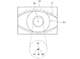
- FIGS. 7 and 10 show how the XY alignment index light Ra from the XY alignment index projection optical system 22 reaches the eye E and the eye Ei in an easy-to-understand manner. It does not agree with the state.
- FIGS. 11 and 13 it is assumed that the bright spots formed in the anterior segment image of the eye E are formed on the same X axis including the corneal apex Ea in order to simplify the description. However, it does not necessarily match the aspect actually formed in the anterior segment image of the eye E.
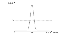
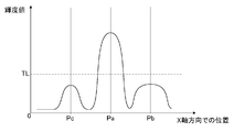
- FIGS. 9, 12 and 14 show the luminance distribution corresponding to FIGS.
- FIG. 9, FIG. 12, FIG. 14, FIG. 15 and FIG. 16 in order to facilitate understanding, as with the corneal reflection luminescent spot image position Pa with respect to the corneal reflection luminescent spot image Sa, the front bright spot image is displayed.
- the front bright spot image position Pb is shown with respect to Sb
- the rear bright spot image position Pc is shown with respect to the rear bright spot image Sc.
- the alignment index light is irradiated to the eye E.
- XY alignment index light as an example of the alignment index light is indicated with a symbol Ra, and is also referred to as XY alignment index light Ra below.
- a bright spot image (Sa) as a virtual image is formed by the XY alignment index light Ra through the cornea Ec.
- the bright spot image (Sa) is formed by reflection from the cornea Ec, and is formed at an intermediate position between the cornea vertex Ea of the cornea Ec and the center of curvature of the cornea Ec. Therefore, the bright spot image (Sa) has a position r / 2 from the corneal apex Ea (curvature radius r) on the axis passing through the corneal apex Ea and the center of curvature of the cornea Ec, where r is the radius of curvature of the cornea Ec. Is 8 mm, it is formed at a position 4 mm from the corneal apex Ea).
- the bright spot image is hereinafter referred to as a corneal reflection bright spot image Sa.
- the anterior eye portion observation optical system 21 forms an anterior eye portion image of the eye E on the CCD camera 21i, and the anterior eye on which the CCD camera 21i is formed.
- a signal based on the reception of the partial image is output to the control unit 33 (see FIG. 2).
- the intraocular pressure measurement unit 20 can acquire an image (its data) of the anterior ocular segment image on which the corneal reflection bright spot image Sa is formed.
- the control part 33 can display the image (the data) acquired with CCD camera 21i (anterior eye part observation optical system 21) on the display part 14 (refer FIG. 1), as shown in FIG.
- the anterior segment image on which the corneal reflection luminescent spot image Sa is formed can be displayed on the display unit 14.
- the XY alignment index projection optical system 22 and the anterior ocular segment observation optical system 21 generate a corneal reflection bright spot image Sa on an axis passing through the corneal vertex Ea and the center of curvature of the cornea Ec. Then, an image (the data) of the anterior segment image on which the corneal reflection bright spot image Sa is formed is acquired.
- the XY alignment index projection optical system 22 that irradiates the eye Ei with the light (infrared light) emitted from the XY alignment light source 22a as the XY alignment index light Ra, and the XY alignment index light Ra.
- the anterior ocular segment observation optical system 21 that acquires the image (the data) of the anterior ocular segment image on which the corneal reflection bright spot image Sa is formed functions as a bright spot image acquiring optical system.
- the control unit 33 detects the position of the corneal reflection bright spot image Sa in the anterior segment image based on the anterior segment image (data).
- the position of the corneal reflection luminescent spot image Sa is detected by obtaining the position of the center of gravity of the location recognized as the corneal reflection luminescent spot image Sa.
- the periphery of the corneal reflection bright spot image Sa has a luminance distribution as shown in FIG.
- a detection threshold TL for detecting the corneal reflection luminescent spot image Sa is set, and a luminance distribution exceeding the detection threshold TL is detected as the corneal reflection luminescent spot image Sa.
- the detection threshold value TL prevents a detection omission of the corneal reflection luminescent spot image Sa due to individual differences and the like, and prevents a luminescent spot other than the corneal reflection luminescent spot image Sa from being erroneously detected. Is set to Then, by detecting the barycentric position from the luminance distribution as the corneal reflection luminescent spot image Sa, the corneal reflection luminescent spot image position Pa indicating the position of the corneal reflection luminescent spot image Sa can be obtained. Note that the center of gravity detection is actually performed on the XY plane.
- the corneal reflection luminescent spot image Sa is formed on the axis passing through the corneal apex Ea and the center of curvature of the cornea Ec as described above, the corneal reflection luminescent spot image Sa on the XY plane.
- the apparatus main body unit 13 intraocular pressure measurement unit 20
- the apparatus main body unit 13 is appropriately moved in the XY directions so that the optical axis O1 of the intraocular pressure measurement unit 20 coincides with the corneal apex Ea (corneal reflection bright spot image position Pa). By doing so, alignment in the XY directions is automatically performed.
- This is aimed at the position of the corneal reflection luminescent spot image Sa (corneal reflection luminescent spot image position Pa) in the image of the eye E acquired by the luminescent spot image acquisition optical system without performing the luminescent spot image dimming control described later.
- the normal alignment mode in which the intraocular pressure measurement unit 20 (device main body unit 13) as an example of the eye characteristic measurement unit is moved is set.
- an eye to be examined (hereinafter also referred to as an eye to be examined Ei (refer to FIG. 10)) to which an intraocular lens (IOL (Intraocular lens)) 51 is attached is measured.
- the intraocular lens 51 is a lens that is transplanted in place of the lens extracted in an operation for an eye disease such as a cataract.
- a front bright spot image Sb and a rear bright spot image Sc are formed separately from the corneal reflection bright spot image Sa.
- the corneal vertex Ea (corneal reflection bright spot image position Pa) may not be detected properly.
- the refractive index of the intraocular lens 51 is different depending on the manufacturer and the type, and it is likely to occur when the difference in refractive index from the crystalline lens is large. Hereinafter, this will be described with reference to FIGS.
- a corneal reflection bright spot image Sa is formed. Since the corneal reflection bright spot image Sa is formed by reflection from the cornea Ec as described above, it is the same as the eye E to which the intraocular lens 51 is not attached, and the corneal vertex Ea of the cornea Ec It is formed at an intermediate position (a position r / 2 from the corneal apex Ea) with the center of curvature of the cornea Ec.
- the front side bright spot image Sb is formed (formed) on the front side (the intraocular pressure measuring unit 20 (ophthalmic apparatus 10) side) of the corneal reflection bright spot image Sa.
- the irradiated XY alignment index light Ra is the back surface 51a of the intraocular lens 51 (the surface opposite to the intraocular pressure measurement unit 20 (ophthalmologic apparatus 10) (the surface of the fundus Ef)). It is formed by the reflected light reflected.
- the position where the front side bright spot image Sb is formed varies depending on individual differences, that is, the subject's eye Ei (its intraocular lens 51), but in many cases, the front side of the cornea Ec (the intraocular pressure measuring unit 20 (ophthalmology)).
- This front side luminescent spot image Sb is formed in the apparatus 10) and has a relatively small imaging magnification and is condensed as a small spot, so that it may have a relatively high luminance.
- a rear bright spot image Sc is formed (imaged) on the rear side of the cornea reflection bright spot image Sa (on the side opposite to the intraocular pressure measurement unit 20 (ophthalmologic apparatus 10) (fundus Ef side)).
- the subsequent bright spot image Sc is formed by the reflected light of the irradiated XY alignment index light Ra reflected by the front surface 51b of the intraocular lens 51 (on the intraocular pressure measurement unit 20 (ophthalmologic apparatus 10) side).
- the position where the rear side bright spot image Sc is formed also varies depending on individual differences, that is, the eye Ei (the intraocular lens 51).
- the rear side bright spot image Sc has a relatively large imaging magnification and is focused on a large spot, and therefore has a lower brightness than the front side bright spot image Sb.
- the anterior ocular segment observation optical system 21 (the CCD camera 21i) is used.
- the corneal reflection bright spot image position Pa is obtained by detecting the barycentric position of the corneal reflection bright spot image Sa including the front bright spot image Sb and the rear bright spot image Sc superimposed as described above.
- the corneal vertex Ea can be detected.
- the front luminescent spot image Sb and the rear luminescent spot image Sc are not necessarily formed on the axis passing through the corneal apex Ea and the center of curvature of the cornea Ec, and are shifted in the X-axis direction or the Y-axis direction. May be formed. An example of this is shown in FIG. In the example shown in FIG. 11, the front bright spot image Sb and the rear bright spot image Sc are formed on the same X axis including the corneal reflection bright spot image Sa (corneal apex Ea) in order to simplify the description. It is assumed that In the anterior segment image (its data), the periphery of the corneal reflection luminescent spot image Sa, the front luminescent spot image Sb, and the rear luminescent spot image Sc has a luminance distribution as shown in FIG. And
- the corneal reflection luminescent spot image Sa exceeds the detection threshold TL, but the front luminescent spot image Sb is smaller than the corneal reflection luminescent spot image Sa, but exceeds the detection threshold TL.
- the rear bright spot image Sc is smaller than the front bright spot image Sb and does not exceed the detection threshold TL. This is due to the following.
- the cornea reflection bright spot image Sa Since the corneal reflection bright spot image Sa is formed as described above, the cornea reflection bright spot image Sa has a larger value than the front bright spot image Sb and the rear bright spot image Sc and the focus of the anterior ocular segment observation optical system 21. Therefore, the image (its data) also has a larger value than the front side bright spot image Sb and the rear side bright spot image Sc, resulting in a small spot (see FIG. 11).
- the front-side bright spot image Sb is a spot that is larger than the corneal reflection bright spot image Sa because the anterior eye portion observation optical system 21 is out of focus. Small brightness value.
- the detection threshold value TL is exceeded.
- whether or not the front side bright spot image Sb exceeds the detection threshold value TL varies depending on individual differences, but particularly in the case of the intraocular lens 51 having a large refractive index difference from the crystalline lens. The possibility of exceeding TL increases. This is because the front side bright spot image Sb is formed by the reflected light reflected by the back surface 51a of the intraocular lens 51. Therefore, if the refractive index difference from the crystalline lens is large, the intraocular lens 51 (back) This is because the reflectance at the surface 51a) is increased.
- the rear bright spot image Sc is largely deviated from the front bright spot image Sb due to the configuration of the anterior eye observation optical system 21 and the nature formed in the eye Ei to be examined. As a result, the spot becomes more blurred than the front side bright spot image Sb, and the brightness value is smaller than that of the front side bright spot image Sb. Since the rear bright spot image Sc has a lower luminance than the front bright spot image Sb as described above, the detection threshold value TL is not exceeded in an out-of-focus image (that data). .
- the luminance value of the rear bright spot image Sc also varies depending on individual differences. However, the luminance value of the rear bright spot image Sc is smaller than that of the front bright spot image Sb for the reasons described above. In the data), the detection threshold value TL is hardly exceeded.
- the control unit 33 includes the corneal reflection luminescent spot image Sa exceeding the detection threshold TL in the anterior eye image (the data) of the eye Ei to be examined. Both the front side bright spot image Sb are detected as bright spot images.
- a light source XY alignment light source 22a of the XY alignment index light Ra irradiated to the eye Ei to be examined. ) May be controlled to blink.
- both the corneal reflection bright spot image Sa and the front bright spot image Sb blink in synchronization with the XY alignment index light Ra. Therefore, it is impossible to prevent the front side bright spot image Sb from being erroneously detected as the bright spot image.
- the control unit 33 cannot determine which of the corneal reflection luminescent spot image Sa and the front luminescent spot image Sb is the correct luminescent spot image (corneal reflection luminescent spot image Sa). Then, since the cornea apex Ea of the cornea Ec of the anterior eye part cannot be detected properly, it becomes impossible to properly perform alignment in the XY directions.
- FIGS. 13 and 14 another example in which the front side bright spot image Sb ′ and the rear side bright spot image Sc ′ are formed at positions shifted in the X-axis direction or the Y-axis direction is shown in FIGS. 13 and 14.
- the front side bright spot image Sb ′ and the rear side bright spot image Sc ′ are formed on the same X axis including the corneal reflection bright spot image Sa ′ (corneal vertex Ea) as in FIG. But they overlap each other.
- the corneal reflection luminescent spot image Sa ′, the front luminescent spot image Sb ′, and the rear luminescent spot image Sc ′ have the same brightness value as the example shown in FIG. 12 (FIG. 11) except that their positions are different. It shall be.
- the corneal reflection luminescent spot image Sa ′ exceeds the detection threshold TL
- the front luminescent spot image Sb ′ exceeds the detection threshold TL with a value smaller than the corneal reflection luminescent spot image Sa ′.
- the point image Sc ′ is smaller than the front bright point image Sb ′ and does not exceed the detection threshold TL.
- the control unit 33 in the image (data) of the anterior segment image of the eye Ei to be examined, the corneal reflection bright spot image Sa ′ that exceeds the detection threshold TL. And the front side bright spot image Sb ′ are detected as bright spot images. That is, in the image (data) of the anterior segment image of the eye Ei to be examined, the detected bright spot image, that is, the corneal reflection bright spot image Sa ′ and the front bright spot image Sb ′ partially overlap, It is considered to be greatly different from the circular shape.
- the controller 33 obtains the correct corneal reflection luminescent spot image position Sa ′ (corneal reflection luminescent spot image position Pa ′). Also, the position displaced toward the front bright spot image Sb ′ (front bright spot image position Pb ′) is obtained as the position of the corneal reflection bright spot image Sa ′, and the correct corneal reflection bright spot image position Pa ′ can be obtained. Can not. Then, since the cornea apex Ea of the cornea Ec of the anterior eye part cannot be detected properly, it becomes impossible to properly perform alignment in the XY directions.
- the intraocular pressure measurement unit 20 (ophthalmologic apparatus 10) cannot appropriately detect the corneal vertex Ea (corneal reflection luminescent spot image position Pa) of the eye Ei to which the intraocular lens 51 is attached. In this case, automatic alignment in the XY directions cannot be properly performed.
- the front side bright spot image Sb and the rear side bright spot image Sc are also formed with a normal crystalline lens, but compared with the reflectance at the cornea Ec (corneal reflective bright spot image Sa), the normal crystalline lens. Therefore, even if the rear side bright spot image Sc is the front side bright spot image Sb, the detection threshold value TL is not exceeded. In other words, the detection threshold TL is set to a value larger than that of the front bright spot image Sb formed of a normal crystalline lens.
- the intraocular pressure measurement unit 20 enables automatic alignment with the eye Ei.
- Intraocular lens alignment mode is set.
- a corneal reflection luminescent spot image Sa is formed by reflection from the cornea Ec on an axis passing through the corneal vertex Ea and the center of curvature of the cornea Ec, and the corneal reflection luminescent spot image Sa is formed.
- the bright spot image acquisition optical system that acquires the image (the data) of the anterior segment image
- the bright spot image dimming control for reducing the luminance value of the front bright spot image Sb on the image (the data) is performed.
- the bright spot image dimming control is performed by the front bright spot image Sb on the image (data) of the anterior segment image acquired by the anterior segment observation optical system 21 (the CCD camera 21i) as the luminescent spot image acquisition optical system.
- the luminance value is reduced. There are the following two methods for reducing the luminance value of the front side bright spot image Sb.
- the first is the light amount of the XY alignment light source 22a (see FIG. 3) of the XY alignment index projection optical system 22 which is the light source of the XY alignment index light Ra irradiated to the eye Ei in the bright spot image acquisition optical system. Is to lower. This is because the front side bright spot image Sb is formed by the XY alignment index light Ra being reflected by the back surface 51a of the intraocular lens 51 (its reflected light) in the eye Ei as described above. It depends.
- the first method is performed by reducing the amount of light of the XY alignment light source 22a under the control of the control unit 33 (see FIG. 2).
- FIG. 15 shows a state in which the light amount of the light source 22a for XY alignment is lowered with respect to the eye Ei having the light amount distribution shown in FIG.
- the front side bright spot image Sb can be set to a value smaller than the detection threshold value TL.
- the luminance values of the corneal reflection luminescent spot image Sa and the rear luminescent spot image Sc are also reduced substantially uniformly. .
- the corneal reflection bright spot image Sa has a larger value than the front bright spot image Sb on the anterior segment image (its data) as described above, and therefore the light quantity of the XY alignment light source 22a is reduced.
- the amount of decrease in the amount of light may be set based on the data of the corneal reflection luminescent spot image Sa and the front luminescent spot image Sb for many eyes Ei to be examined. Note that it is conceivable to increase the detection threshold TL based on the same technical idea as the first one.
- the luminance value of the point image Sb can be relatively reduced.
- the increase amount of the detection threshold TL can be set similarly to the decrease amount of the light amount.
- the anterior eye observation optical system 21 that acquires the image (data) of the anterior segment image on which the corneal reflection bright spot image Sa is formed (focused position) (Focus position) is shifted to the rear bright spot image Sc side (fundus Ef side of the eye Ei to be examined).
- the in-focus position of the anterior ocular segment observation optical system 21 is shifted to the rear bright spot image Sc side, it is relatively compared with the normal state in which the focus position is adjusted to the corneal reflection bright spot image Sa. Since the front bright spot image Sb moves away from the in-focus position, the image of the anterior segment image (its data) is more blurred.
- the control unit 33 see FIG.
- the CCD camera 21i is moved from the first focal position f1, which is the normal measurement position, by the focusing drive mechanism 21D. It is moved along the optical axis O1 to the bifocal position f2 side (see FIG. 3). Thereby, the focusing position of the anterior ocular segment observation optical system 21 can be shifted from the position (the vicinity thereof) where the corneal reflection luminescent spot image Sa is formed to the rear luminescent spot image Sc side.
- the amount of movement of the CCD camera 21i toward the second focal position f2 may be the second focal position f2, which is before the second focal position f2 (on the first focal position f1 side).
- the moving direction of the CCD camera 21 i may be set as long as the in-focus position is shifted to the rear bright spot image Sc side, and may be set as appropriate according to the configuration of the anterior ocular segment observation optical system 21.
- the in-focus position of the anterior segment observation optical system 21 is the corneal reflection. The position is shifted from the position (the vicinity thereof) where the bright spot image Sa is formed to the rear bright spot image Sc side.
- the in-focus position of the anterior ocular segment observation optical system 21 is the position where the corneal reflection luminescent spot image Sa is formed (the vicinity thereof).
- the front bright spot image Sb side the side opposite to the fundus oculi Ef in the eye Ei to be examined.
- the front side bright spot image Sb and the rear side bright spot image Sc with respect to the action with respect to the first method. Will be replaced, not changed.
- FIG. 16 shows a state where the in-focus position is shifted to the rear bright spot image Sc side with respect to the eye Ei having the light amount distribution shown in FIG.
- the image Sb can be set to a value smaller than the detection threshold TL.
- the corneal reflection bright spot image Sa is slightly blurred on the image (the data) of the anterior segment image.
- the Rukoto since the corneal reflection luminescent spot image Sa has a larger value than the front luminescent spot image Sb on the anterior eye image (its data) as described above, the rear luminescent spot image at the in-focus position.
- the corneal reflection luminescent spot image Sa can be detected by exceeding the detection threshold TL, and the centroid position is obtained to obtain the corneal reflection luminescent spot image Sa.
- the point image position Pa can be obtained. That is, even if the corneal reflection luminescent spot image Sa is blurred, the position of the center of gravity in the luminance distribution of the corneal reflection luminescent spot image Sa does not change, so that the corneal reflection luminescent spot image position is the same as in the normal alignment mode. Pa can be obtained.
- the second method since the in-focus position is shifted toward the rear bright spot image Sc, the rear bright spot image Sc approaches the in-focus position.
- the rear side bright spot image Sc is smaller in value than the front side bright spot image Sb on the anterior segment image (its data) as described above.
- a value smaller than the detection threshold TL can be set by appropriately setting the shift amount to the Sc side.
- the shift amount toward the subsequent bright spot image Sc may be set based on the data of the corneal reflection bright spot image Sa, the front bright spot image Sb, and the rear bright spot image Sc with respect to many eyes Ei to be examined.
- the above two methods are performed together in the bright spot image dimming control. That is, in the bright spot image dimming control, the light amount of the XY alignment light source 22a is reduced and the focusing position in the anterior ocular segment observation optical system 21 is shifted to the rear bright spot image Sc side.
- FIG. 17 is a flowchart showing an alignment mode switching process (alignment mode switching method) executed by the control unit 33 in this embodiment.
- This alignment mode switching process (alignment mode switching method) is executed by the control unit 33 based on a program stored in a storage unit built in the control unit 33 or a storage unit provided outside the control unit 33.
- each step (each process) of the flowchart of FIG. 17 as an alignment mode switching process (alignment mode switching method) is demonstrated. This flowchart is started when an operation to execute measurement by the intraocular pressure measurement unit 20 is performed.
- step S1 it is determined whether or not the intraocular lens alignment mode is selected. If YES, the process proceeds to step S2, and if NO, the process proceeds to step S5.
- step S1 when the intraocular lens alignment mode is selected, since the measurement target is the eye Ei to be examined, the process proceeds to step S2 to execute the intraocular lens alignment mode, that is, the bright spot image dimming control.
- step S1 when the intraocular lens alignment mode is not selected, the measurement target is the normal eye E, and thus the process proceeds to step S5 to execute the normal automatic alignment mode.
- the intraocular lens alignment mode is selected by providing a selection operation unit for selecting either the intraocular lens alignment mode or the normal alignment mode, and the control unit 33 performs an operation performed on the selection operation unit.
- the selection operation unit can be realized, for example, by displaying an icon for selecting an intraocular lens alignment mode on the display unit 14. Note that the selection operation unit may be provided with a selection operation switch in the apparatus main body unit 13 or the like.
- step S2 following the determination that the intraocular lens alignment mode has been selected in step S1, the light reduction amount in the bright spot image dimming control is set, and the process proceeds to step S3.
- a light reduction amount in the bright spot image dimming control that is, a reduction amount of the light quantity of the XY alignment light source 22a, and a shift amount to the rear bright spot image Sc side of the in-focus position are set.
- the reduction amount and the shift amount are set in advance by setting the light reduction amount in the bright spot image dimming control according to the manufacturer and type of the intraocular lens 51. By selecting the company and type, the light reduction amount is set according to the selection.
- This selection can be performed, for example, by displaying an icon for selecting the manufacturer or type of the intraocular lens 51 on the display unit 14.
- the setting of the light reduction amount in the bright spot image dimming control may be arbitrarily set. In that case, the setting of the light reduction amount in the bright spot image dimming control may be arbitrary. This setting can be performed, for example, by displaying an icon for setting a light reduction amount on the display unit 14. Further, it may be possible to arbitrarily and arbitrarily set the amount of decrease in the amount of light of the XY alignment light source 22a and the shift amount to the rear bright spot image Sc side of the in-focus position. This setting can be performed, for example, by causing the display unit 14 to display an icon for setting a reduction amount and an icon for setting a shift amount.
- step S3 following the setting of the light reduction amount in the bright spot image dimming control in step S2, the bright spot image dimming control is executed, and the process proceeds to step S4.
- step S3 the light amount of the XY alignment light source 22a is decreased and the CCD camera 21i is moved to the second focal position f2 side so as to obtain the light reduction amount set in step S2.
- step S4 following the execution of the bright spot image dimming control in step S3, automatic alignment is performed under the setting by the bright spot image darkening control, and the process proceeds to step S6.
- automatic alignment that is, automatic alignment in the intraocular lens alignment mode is performed under the setting by the bright spot image dimming control executed in step S3.
- the eye Ei to be examined is irradiated with the XY alignment index light Ra emitted from the XY alignment light source 22a and having passed through the airflow blowing nozzle 21b with the light amount reduced in step S3.
- step S4 the anterior segment image in which the corneal reflection luminescent spot image Sa, the front luminescent spot image Sb, and the rear luminescent spot image Sc are formed by the XY alignment index light Ra is used as the second focal position f2 in step S3. Obtained by the CCD camera 21i moved to the side.
- step S4 from the image (the data) of the anterior segment image in which the corneal reflection luminescent spot image Sa, the front luminescent spot image Sb, and the rear luminescent spot image Sc thus obtained are formed, the detection threshold TL is used.
- the corneal reflection bright spot image Sa is detected, and the corneal vertex Ea in the eye Ei to be examined is detected by obtaining the corneal reflection bright spot image position Pa.
- step S4 the apparatus main body 13 (intraocular pressure measurement unit 20) is appropriately moved in the XY directions so that the optical axis O1 of the intraocular pressure measurement unit 20 coincides with the corneal apex Ea (corneal reflection bright spot image position Pa). By doing so, alignment in the XY directions is automatically performed.
- step S5 following the determination that the intraocular lens alignment mode is not selected in step S1, normal automatic alignment is performed, and the process proceeds to step S6.
- step S5 since the intraocular lens alignment mode is not selected, the normal eye E is the object to be measured, so that the normal automatic alignment, that is, the automatic alignment in the normal alignment mode is performed as described above. .
- step S6 automatic alignment is performed under the setting of bright spot image dimming control in step S4, or normal automatic alignment in step S5, and measurement is performed by the intraocular pressure measurement unit 20 to switch the alignment mode.
- the process ends.
- step S6 the intraocular pressure of the eye Ei or the eye E is measured by the intraocular pressure measurement unit 20 as described above.
- the examiner selects whether or not to set the intraocular lens alignment mode using the icon (selection operation unit) displayed on the display unit 14.
- the process proceeds from step S1 to step S2 in the flowchart of FIG. Icons for selecting the manufacturer and type are displayed.
- the examiner can set the light reduction amount in the luminescent spot image dimming control suitable for the eye Ei by selecting an icon that matches the intraocular lens 51 attached to the eye Ei.
- step S3 the process proceeds from step S3 to step S4, so that the light intensity suitable for the eye Ei is obtained by the bright spot image dimming control, and automatic alignment is performed under the setting. Thereby, even if it is eye Ei to which any intraocular lens 51 was equipped, cornea apex Ea can be detected appropriately and automatic alignment can be performed appropriately. Thereafter, in the flowchart of FIG. 17, the intraocular pressure measurement unit 20 measures the intraocular pressure of the eye Ei by proceeding to step S ⁇ b> 6.
- the process proceeds from step S1 to step S5 in the flowchart of FIG. Normal automatic alignment is performed on the eye E. Thereafter, in the flowchart of FIG. 17, the intraocular pressure measurement unit 20 measures the intraocular pressure of the eye E by proceeding to step S ⁇ b> 6.
- the ophthalmologic apparatus 10 is suitable for selecting the eye Ei to which the intraocular lens 51 is attached or the normal eye E simply by selecting whether or not the intraocular lens alignment mode is selected. Alignment can be automatically performed, and the intraocular pressure of the eye E (Ei) to be examined can be measured by the intraocular pressure measurement unit 20.
- the intraocular pressure can be measured by the intraocular pressure measuring unit 20 for the eye E (Ei) to be examined, and the shape of the cornea Ec and the eye refractive power can be measured by the ocular characteristic measuring unit 40. (Spherical power, astigmatic power, astigmatic axis angle, etc.) can be measured. And although illustration is omitted, in the ophthalmologic apparatus 10, a pachymeter for measuring the thickness of the cornea (measuring the corneal thickness) is mounted on the intraocular pressure measurement unit 20, and the thickness of the cornea of the eye E (Ei) to be examined is mounted. It is possible to measure.
- control unit 33 it is possible to store the various measurement results (its data) described above in association with the measurement conditions (the data) at the time of the measurement.
- the storage is performed by a storage unit built in the control unit 33 or a storage unit provided outside the control unit 33 under the control of the control unit 33.
- the control unit 33 can transmit the stored measurement results and the measurement conditions (the data) to an external device different from the ophthalmologic apparatus 10.
- control unit 33 can read the stored measurement conditions, and can apply the read measurement conditions to the intraocular pressure measurement unit 20 and the eye characteristic measurement unit 40.
- Application of the read measurement conditions to the intraocular pressure measurement unit 20 and the eye characteristic measurement unit 40 can be performed or not.
- the selection of the presence / absence of execution can be performed, for example, by displaying an icon for applying the measurement condition on the display unit 14.
- the control unit 33 can print out the measurement results and the measurement conditions using a printer provided in the ophthalmologic apparatus 10 or a printer as an external device. Moreover, the control part 33 can display a measurement result and its measurement conditions on the display part 14, or an external apparatus connected by wire or wirelessly.
- control part 33 can select suitably the content to describe (display). That is, the control unit 33 performs various measurement results (eye refractive power measurement value 53, corneal shape measurement value 54, intraocular pressure measurement value 55, corneal thickness measurement value 56, and the like) described below and various measurement conditions (eye characteristic measurement). Can be selected as appropriate from among the part measurement conditions 57, the intraocular pressure measurement part measurement conditions 58, etc.) and the barcode 59 (see FIG. 18).
- the control unit 33 also includes items in various measurement results to be described later and items in various measurement conditions (CAT mode 57a, fixation target brightness 57b, cloud fog condition 57c, measurement mode 57d, IOL mode 58a, and measurement range 58b. , Measurement mode 58c, etc.), it is possible to appropriately select one to be described (displayed) (see FIG. 18).
- FIG. 18 shows an output result 52 as an example in which the control unit 33 prints out the measurement result and the measurement conditions.
- an eye refractive power measurement value 53 a corneal shape measurement value 54
- an intraocular pressure measurement value 55 a corneal thickness measurement value 56
- the eye characteristic measurement unit measurement condition 57 and the intraocular pressure measurement unit measurement condition 58 are described as measurement conditions.
- a barcode 59 is described.
- the eye refractive power measurement value 53 indicates a measurement value of the eye refractive power (spherical power, astigmatism power, astigmatic axis angle, etc.) measured by the eye characteristic measuring unit 40.
- the corneal shape measurement value 54 indicates a measurement value of the shape of the cornea Ec measured by the eye characteristic measurement unit 40.
- the intraocular pressure measurement value 55 indicates the measurement value of the intraocular pressure of the eye E measured by the intraocular pressure measurement unit 20.
- the corneal thickness measurement value 56 indicates a measurement value of the thickness of the cornea Ec measured by the intraocular pressure measurement unit 20.
- the eye characteristic measurement unit measurement condition 57 is performed by the eye characteristic measurement unit 40 when the eye characteristic measurement unit 40 measures the eye refractive power (eye refractive power measurement value 53) and the shape of the cornea Ec (corneal shape measurement value 54).
- Various setting conditions are shown.
- the eye characteristic measurement unit measurement condition 57 includes, as setting conditions, a CAT mode 57a, a fixation target brightness 57b, a cloud condition 57c, and a measurement mode 57d.
- the CAT mode 57a indicates whether or not the CAT mode is set. In the example shown in FIG. 18, the CAT mode 57a indicates that the CAT mode is not set.
- the CAT mode is a measurement that is adapted to the subject eye (cataract eye) that has developed cataract.
- the ocular refractive power measurement ring-shaped index projection optical system 43 causes the ocular refractive power measurement ring-shaped index formed on the fundus oculi to be partially broken.
- the ring indicator for force measurement may not be in an appropriate state.
- the appropriate state of the ring-shaped index for measuring eye refractive power means a state where appropriate measurement can be performed.
- the control unit 33 when the ring index for measuring eye refractive power is not in an appropriate state, it is determined that appropriate measurement cannot be performed and measurement is not performed. In this CAT mode, even when the eye refractive power measurement ring index is not in an appropriate state, the measurement is performed using the eye refractive power measurement ring index.
- the fixation target brightness 57b indicates the brightness of the fixation target that the subject is gazing at as a fixation target, that is, the brightness of the target luminous flux that is advanced to the eye E (Ei) by the fixation target projection optical system 41. Is.
- the brightness of the fixation target can be switched between two levels, bright and dark, and the light amount of the fixation target light source 41a can be switched.
- This fixation target brightness 57b indicates that it is dark in the example shown in FIG.
- the fixation target unit 41U is moved in the fixation target projection optical system 41 so that the eye E is brought into a cloud state only when the measurement is started. (Performs only once for the first time) or for each of a plurality of measurements.
- This cloud fog condition 57c indicates that only the first time is set in the example shown in FIG.
- the measurement mode 57d indicates whether the measurement by the eye characteristic measurement unit 40 is performed manually or automatically. This measurement mode 57d indicates that it is automatically performed.
- the setting condition in the eye characteristic measurement unit measurement condition 57 is that the eye characteristic measurement unit 40 measures the eye refractive power (eye refractive power measurement value 53) and the shape of the cornea Ec (corneal shape measurement value 54).
- Various setting conditions in the unit 40 may be used, and are not limited to those described above.
- the number of times of measurement indicating the number of times of continuous measurement that can be set in the eye characteristic measurement unit 40 can be given.
- the number of times of measurement may be a number indicating the set number of times, that is, the number of times of continuous measurement.
- the setting condition is convenient when it can be grasped when diagnosing the eye E (Ei) to be examined using the measurement result, and is convenient when it can be grasped when measuring next, Etc. may be stored.
- the intraocular pressure measurement unit measurement condition 58 is the measurement of intraocular pressure when the intraocular pressure measurement unit 20 measures the intraocular pressure (intraocular pressure measurement value 55) and the thickness of the cornea Ec (corneal thickness measurement value 56).
- Various setting conditions in the unit 20 are shown.
- the eye characteristic measurement unit measurement condition 57 has an IOL mode 58a, a measurement range 58b, and a measurement mode 58c as setting conditions.
- the IOL mode 58a indicates whether or not the above-described intraocular lens alignment mode is set.
- the IOL mode 58a indicates that the intraocular lens alignment mode is not set in the example shown in FIG.
- the measurement range 58b indicates a range (range) of intraocular pressure of the eye E that can be measured by the intraocular pressure measurement unit 20.
- the intraocular pressure measurement unit 20 is set to two modes: a mode up to 30 (mmHg) (1 to 30 (mmHg)) and a mode up to 60 (mmHg) (1 to 60 (mmHg)). ing.
- the measurement range is switched by changing the pressure in the airflow blown from the airflow blowing mechanism 34.
- This measurement range 58b indicates that the mode up to 30 (mmHg) is set in the example shown in FIG.
- the measurement mode 58c indicates whether the measurement by the intraocular pressure measurement unit 20 is performed manually or automatically. This measurement mode 58c indicates that it has been automatically performed.
- the setting conditions in the intraocular pressure measurement unit measurement condition 58 are the conditions when the intraocular pressure measurement unit 20 measures the intraocular pressure (intraocular pressure measurement value 55) of the eye E and the thickness of the cornea Ec (corneal thickness measurement value 56).
- Various setting conditions in the intraocular pressure measurement unit 20 may be used, and the present invention is not limited to those described above.
- this setting condition for example, the number of times of measurement indicating the number of times of continuous measurement that can be set in the intraocular pressure measurement unit 20 is given.
- the number of times of measurement may be a number indicating the set number of times, that is, the number of times of continuous measurement.
- the setting condition includes, for example, patch correction that indicates whether or not the measurement of the thickness of the cornea Ec is included in the tonometry part 20.
- the setting condition is convenient when it can be grasped when diagnosing the eye E (Ei) to be examined using the measurement result, and is convenient when it can be grasped when measuring next, Etc. may be stored.
- the bar code 59 stores information on the measurement conditions described (displayed), that is, information on the eye characteristic measurement unit measurement conditions 57 and the intraocular pressure measurement unit measurement conditions 58 in the output result 52 in a readable manner. That is, by reading this bar code 59, it is possible to read the information on the measurement conditions described (displayed), that is, the information on the eye characteristic measurement unit measurement conditions 57 and the intraocular pressure measurement unit measurement conditions 58. .
- the control unit 33 can read the measurement conditions in the output result 52 from the barcode 59 by using a barcode reader mounted on the ophthalmologic apparatus 10 or a barcode reader provided as an external device. The control unit 33 can apply the read measurement conditions to the intraocular pressure measurement unit 20 and the eye characteristic measurement unit 40.
- the ophthalmologic apparatus having this function is not limited to the ophthalmologic apparatus 10 provided with the intraocular pressure measurement unit 20 and the ocular characteristic measurement unit 40 as in the present embodiment, but only the intraocular pressure measurement unit 20. May be configured only by the eye characteristic measuring unit 40, or may be configured by a measuring unit capable of measuring other eye characteristics. In addition, they may be appropriately combined and configured, and are not limited to the present embodiment.
- the luminance value of the front luminescent spot image Sb on the image (the data) of the anterior ocular segment image in the luminescent spot image acquisition optical system of the intraocular pressure measuring unit 20 It has an intraocular lens alignment mode in which alignment is performed automatically while performing bright spot image dimming control to reduce the brightness. For this reason, the ophthalmologic apparatus 10 can prevent the front side bright spot image Sb from being detected as a bright spot image even when the subject's eye Ei to which the intraocular lens 51 is attached is a measurement target. Appropriate automatic alignment can be performed.
- the ophthalmologic apparatus 10 has a normal alignment mode in which alignment is performed automatically without performing bright spot image dimming control by the bright spot image acquisition optical system.
- the normal alignment mode and the intraocular lens alignment mode are Selection is possible. For this reason, in the ophthalmologic apparatus 10, alignment can be automatically performed appropriately according to the eye to be measured.
- the ophthalmologic apparatus 10 can select the intraocular lens alignment mode, when the eye to be measured is recognized as the eye Ei to which the intraocular lens 51 is attached in advance, Since the alignment can be automatically performed in the intraocular lens alignment mode, the time required for the alignment can be reduced, and the burden on the subject can be reduced.
- the luminescent spot image in the luminescent spot image acquisition optical system is reduced by reducing the amount of light of the XY alignment light source 22a of the XY alignment index projection optical system 22 serving as the light source of the XY alignment index light Ra irradiated to the eye Ei. Perform dimming control. Therefore, in the ophthalmologic apparatus 10, the corneal reflection luminescent spot image Sa, the front luminescent spot image Sb, and the rear luminescent spot on the image (the data) of the anterior segment image according to the reduction amount of the light amount of the XY alignment light source 22a. The luminance value with the point image Sc can be reduced uniformly.
- the cornea of the corneal reflection luminescent spot image Sa is the same as in the case where the luminescent spot image dimming control is not performed.
- the reflected bright spot image position Pa can be obtained, and the corneal vertex Ea of the eye Ei to be examined can be detected.
- the luminescent spot image in the luminescent spot image acquisition optical system is reduced by reducing the amount of light of the XY alignment light source 22a of the XY alignment index projection optical system 22 serving as the light source of the XY alignment index light Ra irradiated to the eye Ei. Perform dimming control. For this reason, in the ophthalmologic apparatus 10, it is possible to execute the bright spot image dimming control in the bright spot image acquisition optical system without causing a large change in configuration.
- the in-focus position of the anterior ocular segment observation optical system 21 that acquires the image (the data) of the anterior ocular segment image on which the corneal reflection luminescent image Sa is formed is shifted to the rear luminescent image Sc.
- bright spot image dimming control is performed in the bright spot image acquisition optical system.
- the luminance value of the front side bright spot image Sb on the image (its data) is reduced by greatly blurring the front side bright spot image Sb, so that the corneal reflection bright spot image Sa and the rear bright spot point are reduced. It is possible to reduce the luminance value of the front bright spot image Sb while reducing the influence on the luminance value of the image Sc.
- the ophthalmologic apparatus 10 can prevent the corneal reflection luminescent spot image Sa from being detected from the detection threshold TL and can prevent the front luminescent spot image Sb from being detected from the detection threshold TL. . Therefore, the ophthalmologic apparatus 10 can more reliably detect the corneal reflection luminescent spot image Sa, and can more reliably determine the corneal reflection luminescent spot image position Pa of the corneal reflection luminescent spot image Sa. It is possible to detect the corneal vertex Ea.
- the in-focus position of the anterior ocular segment observation optical system 21 that acquires the image (the data) of the anterior ocular segment image on which the corneal reflection luminescent image Sa is formed is shifted to the rear luminescent image Sc.
- bright spot image dimming control is performed in the bright spot image acquisition optical system.
- the light quantity of the XY alignment light source 22 a of the XY alignment index projection optical system 22 serving as the light source of the XY alignment index light Ra irradiated to the eye Ei is reduced and before the corneal reflection bright spot image Sa is formed.
- Bright spot image dimming control in the bright spot image acquisition optical system is performed by shifting the in-focus position of the anterior segment observation optical system 21 that acquires the eye part image (data) to the rear bright spot image Sc side. Do. For this reason, in the ophthalmologic apparatus 10, it is possible to more reliably reduce the luminance value of the front luminescent spot image Sb while suppressing the reduction of the luminance value of the corneal reflection luminescent spot image Sa.
- the ophthalmologic apparatus 10 can more reliably detect the corneal reflection luminescent spot image Sa, and can more reliably determine the corneal reflection luminescent spot image position Pa of the corneal reflection luminescent spot image Sa.
- the corneal apex Ea of the optometry Ei can be detected.
- the light quantity of the XY alignment light source 22 a of the XY alignment index projection optical system 22 serving as the light source of the XY alignment index light Ra irradiated to the eye Ei is reduced and before the corneal reflection bright spot image Sa is formed.
- Bright spot image dimming control in the bright spot image acquisition optical system is performed by shifting the in-focus position of the anterior segment observation optical system 21 that acquires the eye part image (data) to the rear bright spot image Sc side. Do. For this reason, in the ophthalmologic apparatus 10, it is possible to further reduce the luminance value of the front luminescent spot image Sb while suppressing changes in the luminance distribution in the corneal reflection luminescent spot image Sa.
- the ophthalmologic apparatus 10 can detect the corneal reflection luminescent spot image Sa more reliably and more appropriately. Therefore, the corneal reflection luminescent spot image position of the corneal reflection luminescent spot image Sa can be detected more reliably and more appropriately. Pa can be obtained, and the corneal apex Ea of the eye Ei to be examined can be detected.
- the CCD camera 21i of the anterior ocular segment observation optical system 21 is moved along the optical axis O1 from the first focus position f1, which is a normal measurement position, to the second focus position f2 side.
- the focus position of the eye part observation optical system 21 is shifted to the rear bright spot image Sc side.
- the focus position of the anterior ocular segment observation optical system 21 can be easily shifted to the rear bright spot image Sc side, the bright spot image dimming in the bright spot image acquiring optical system can be easily performed. Control can be performed.
- the CCD camera 21i of the anterior ocular segment observation optical system 21 is moved along the optical axis O1 from the first focus position f1, which is a normal measurement position, to the second focus position f2 side.
- the focus position of the eye part observation optical system 21 is shifted to the rear bright spot image Sc side.
- the ophthalmic apparatus (intraocular pressure measurement unit 20) on which the focusing drive mechanism 21D that moves the CCD camera 21i along the optical axis O1 is mounted does not cause a change in configuration.
- Bright point image dimming control can be performed in the point image acquisition optical system. Even if it is not mounted, it is only necessary to mount the focusing drive mechanism 21D, so that it is possible to easily perform bright spot image dimming control in the bright spot image acquisition optical system. .
- the ophthalmologic apparatus 10 can make it possible to arbitrarily set the amount of light reduction in the bright spot image dimming control in the bright spot image acquisition optical system. For this reason, in the ophthalmologic apparatus 10, even if it is a case where it does not know the manufacturer and kind of the intraocular lens 51 which the subject wears, it can respond appropriately.
- the ophthalmologic apparatus 10 can appropriately cope with any manufacturing company or type of intraocular lens 51, and has a bright spot set in advance according to the manufacturing company or type of the intraocular lens 51. It is possible to eliminate the necessity of registering the light reduction amount in the image dimming control or reduce the registration amount.
- the ophthalmologic apparatus 10 it is possible to arbitrarily set a reduction amount of the light amount of the XY alignment light source 22 a of the XY alignment index projection optical system 22 as a light source of the XY alignment index light Ra irradiated to the eye Ei. it can. For this reason, in the ophthalmologic apparatus 10, it can respond
- the anterior ocular segment observation optical system 21 that acquires an image (data) of the anterior ocular segment image on which the corneal reflection bright spot image Sa is formed is shifted to the rear bright spot image Sc side.
- the amount can be arbitrarily settable. For this reason, in the ophthalmologic apparatus 10, it can respond
- the ophthalmologic apparatus 10 selects the manufacturer and type of the intraocular lens 51 (selects an icon that matches the intraocular lens 51 attached to the eye Ei to be examined), thereby reducing the amount of light reduction in the luminescent spot image dimming control. It can be set to be suitable for the intraocular lens 51 (the eye Ei to which the eye is attached). For this reason, in the ophthalmologic apparatus 10, the setting of the light reduction amount in the bright spot image dimming control suitable for the eye Ei to be examined can be facilitated.
- the bright spot image dimming control for reducing the brightness value of the front bright spot image Sb on the anterior segment image (its data) in the bright spot image acquisition optical system of the tonometry part 20 is performed. Can do. For this reason, the ophthalmologic apparatus 10 can prevent the front side bright spot image Sb from being detected as a bright spot image even when the subject's eye Ei to which the intraocular lens 51 is attached is a measurement target. Appropriate automatic alignment can be performed.
- the ophthalmologic apparatus 10 can store various measurement results (its data) in association with measurement conditions (its data) when the measurement is performed. For this reason, in the ophthalmologic apparatus 10, it can make it easy to measure according to the measurement conditions in the case of the last measurement. Here, since the measured values slightly change depending on the measurement conditions, it is important to perform measurement together with the measurement conditions when performing continuous follow-up observation. Moreover, although the measurement conditions can be determined by various measurements, the measurement conditions similar to the previous measurement are not necessarily derived only from the results of the measurements. From these things, various measurement results (its data) are stored in association with the measurement conditions (that data) at the time of the measurement, so that measurement can be performed according to the measurement conditions at the previous measurement. Making it easy is very effective.
- the eye refractive power measurement value 53, the corneal shape measurement value 54, the intraocular pressure measurement value 55, the corneal thickness measurement value 56 are described (displayed)
- These measurement conditions in the above-described embodiments, the eye characteristic measurement unit measurement condition 57 and the intraocular pressure measurement unit measurement condition 58) can be described (displayed) together. For this reason, in the ophthalmologic apparatus 10, it is possible to easily grasp the measurement conditions when the measurement is performed.
- a bar that stores information on the measurement conditions described in the output result 52 (in the above-described embodiment, information on the eye characteristic measurement unit measurement conditions 57 and the intraocular pressure measurement unit measurement conditions 58) in a readable manner.
- Code 59 can be described.
- the measurement condition when the measurement result described as the output result 52 is obtained can be read from the barcode 59, and the read measurement condition is used as the intraocular pressure measurement unit 20. It can be easily applied to the eye characteristic measuring unit 40. Thereby, in the ophthalmologic apparatus 10, the operation
- the eye Ei into which the intraocular lens 51 is inserted can be appropriately aligned.
- the ophthalmologic apparatus of the present invention appropriately detects the corneal apex of the eye to be inspected by forming a plurality of bright spot images when the alignment index light is irradiated to the eye to which the intraocular lens is attached. In order to solve the problem that there is room for improvement from the viewpoint of appropriately performing automatic alignment on the eye to be examined in which an intraocular lens is inserted.
- An ophthalmologic apparatus including an eye characteristic measurement unit that measures characteristics, a drive unit that moves the eye characteristic measurement unit with respect to the eye to be examined, a control unit that controls the eye characteristic measurement unit and the drive unit, The eye characteristic measurement unit irradiates the eye to be examined with alignment index light to form a corneal reflection luminescent spot image by reflection from the cornea of the subject eye, and the corneal reflection luminescent spot image is formed.
- the A bright spot image acquisition optical system for acquiring an image of the eye to be examined and the control unit is located on the front side of the corneal reflection bright spot image by irradiating the bright spot image acquisition optical system with the alignment index light While performing the bright spot image dimming control to reduce the luminance value in the image of the eye to be examined of the rear bright spot image formed on the rear side of the front bright spot image or the corneal reflection bright spot image formed on the An intraocular lens alignment mode in which the eye characteristic measurement unit is moved with the position of the corneal reflection luminescent spot image as a target in the image of the eye to be examined acquired by the luminescent spot image acquisition optical system; Thereby, it can align appropriately also to the eye to be examined in which the intraocular lens is inserted.
- control unit targets the position of the corneal reflection luminescent spot image in the eye image acquired by the luminescent spot image acquisition optical system without performing the luminescent spot image dimming control.
- a normal alignment mode for moving the eye characteristic measurement unit and the control unit allows selection between the intraocular lens alignment mode and the normal alignment mode. Accordingly, alignment can be automatically performed appropriately.
- the image processing apparatus further includes a selection operation unit for selecting either the intraocular lens alignment mode or the normal alignment mode, and the control unit performs an operation performed on the selection operation unit. Accordingly, when one of the intraocular lens alignment mode and the normal alignment mode is selected, it is recognized that the eye to be measured is an eye to be examined with an intraocular lens attached in advance. Since the alignment can be performed automatically in the intraocular lens alignment mode from the beginning, the time required for the alignment can be reduced, and the burden on the subject can be reduced.
- control unit detects a bright spot detected by exceeding a detection threshold set to detect the corneal reflection bright spot image in the image of the eye to be examined acquired by the bright spot image acquiring optical system.
- the normal alignment mode is selected when the image state is normal, and the intraocular lens alignment mode is selected when the state of the bright spot image detected by exceeding the detection threshold is not normal. Can be improved.
- the bright spot image acquisition optical system includes an alignment index projection optical system that irradiates the eye to be examined with the alignment index light, and the control unit is for alignment in the alignment index projection optical system.
- the light spot image dimming control is performed by reducing the light amount of the light source, it is possible to execute the bright spot image dimming control in the bright spot image acquiring optical system without causing a large change in the configuration. it can.
- the bright spot image acquisition optical system includes an observation optical system that acquires an image of the eye to be inspected, and the control unit determines the in-focus position in the observation optical system as the corneal reflection brightness.
- the control unit determines the in-focus position in the observation optical system as the corneal reflection brightness.
- the bright spot image acquisition optical system includes an alignment index projection optical system that irradiates the eye to be examined with the alignment index light, and an observation optical system that acquires an image of the eye to be examined.
- the control unit reduces the amount of light of the alignment light source in the alignment index projection optical system and shifts the focus position in the observation optical system from the position of the corneal reflection luminescent spot image, thereby reducing the bright spot image dimming.
- the luminance value of the front luminescent spot image or the rear luminescent spot image can be more reliably reduced while suppressing the reduction of the luminance value of the corneal reflection bright spot image. Therefore, the corneal reflection luminescent spot image can be detected more reliably, the position of the corneal reflection luminescent spot image can be obtained more reliably, and the corneal vertex of the eye to be examined can be detected.
- control unit moves the imaging element that acquires the image of the eye to be examined in the observation optical system on the optical axis of the observation optical system, thereby focusing on the observation optical system. If the position is shifted from the position of the corneal reflection bright spot image, the focus position of the observation optical system can be easily shifted, and bright spot image dimming control in the bright spot image acquisition optical system can be easily performed. it can.
- control unit can appropriately set the amount of light reduction in the bright spot image dimming control. It is possible to cope with
- control unit can more appropriately set the light amount reduction amount of the alignment light source, and more appropriately corresponds to the eye to be examined (intraocular lens attached thereto). can do.
- control unit if it enables arbitrary setting of the in-focus position in the observation optical system, it corresponds more appropriately to the eye to be examined (intraocular lens attached thereto). be able to.
- An ophthalmologic apparatus including an eye characteristic measuring unit that measures an eye characteristic of an eye to be examined, wherein the driving unit moves the eye characteristic measuring unit with respect to the eye to be examined, and controls the eye characteristic measuring unit and the driving unit.
- a control unit wherein the eye characteristic measurement unit forms an image of a corneal reflection luminescent spot by reflection from the cornea of the subject eye by irradiating the eye to be examined with alignment index light, and the corneal reflection luminescent spot
- a bright spot image acquisition optical system for acquiring an image of the eye to be examined on which an image has been formed, and the control unit emits the corneal reflection bright spot by irradiating the bright spot image acquisition optical system with the alignment index light
- An ophthalmologic apparatus comprising an observation optical unit for observing an eye to be examined, comprising: a drive unit that moves the observation optical unit relative to the eye to be examined; and a control unit that controls the observation optical unit and the drive unit
- the observation optical unit forms a corneal reflection luminescent spot image by reflection from the cornea of the subject eye by irradiating the eye to be examined with alignment index light, and the corneal reflection luminescent spot image is formed. It has a bright spot image acquisition optical system for acquiring an optometry image, and the control unit is formed in front of the corneal reflection bright spot image by irradiating the alignment index light to the bright spot image acquisition optical system.
- the bright spot image dimming control is performed to reduce the luminance value in the image of the eye to be inspected of the front bright spot image or the rear bright spot image formed behind the corneal reflection bright spot image.
- the object acquired by the point image acquisition optical system If it has an intraocular lens alignment mode in which the observation optical unit is moved with the position of the corneal reflection luminescent spot image in the eye image as a target, it is also properly aligned with the eye to be examined in which the intraocular lens is inserted. It can be performed.
- An ophthalmologic apparatus comprising an observation optical unit for observing an eye to be examined, comprising: a drive unit that moves the observation optical unit relative to the eye to be examined; and a control unit that controls the observation optical unit and the drive unit
- the observation optical unit forms a corneal reflection luminescent spot image by reflection from the cornea of the subject eye by irradiating the eye to be examined with alignment index light, and the corneal reflection luminescent spot image is formed. It has a bright spot image acquisition optical system for acquiring an optometry image, and the control unit is formed in front of the corneal reflection bright spot image by irradiating the alignment index light to the bright spot image acquisition optical system.
- the intraocular lens is inserted It is possible to enable it to perform properly aligned with respect to the eye.
- the ophthalmologic apparatus 10 as an embodiment of the ophthalmologic apparatus according to the present invention has been described.
- the ophthalmologic apparatus includes an eye characteristic measuring unit that measures the eye characteristics of the eye to be examined.
- a driving unit that moves the eye characteristic measuring unit with respect to the eye examination; and a control unit that controls the eye characteristic measuring unit and the driving unit, wherein the eye characteristic measuring unit applies alignment index light to the eye to be examined.
- a corneal reflection luminescent spot image by reflection from the subject eye by irradiating, and having a luminescent spot image acquisition optical system for acquiring an image of the subject eye on which the corneal reflection luminescent spot image is formed;
- the control unit determines a luminance value in the image of the subject eye of a front side bright spot image formed on the front side of the corneal reflection bright spot image by irradiation of the alignment index light to the bright spot image acquisition optical system.
- Bright spot image dimming control to reduce An ophthalmic apparatus having an intraocular lens alignment mode that moves the eye characteristic measuring unit while aiming at the position of the corneal reflection luminescent spot image in the image of the eye to be examined acquired by the luminescent spot image acquiring optical system.
- Bright spot image dimming control to reduce An ophthalmic apparatus having an intraocular lens alignment mode that moves the eye characteristic measuring unit while aiming at the position of the corneal reflection luminescent spot image in the image of the eye to be examined acquired by the luminescent spot image
- the intraocular lens alignment mode is set in the bright spot image acquisition optical system provided in the intraocular pressure measurement unit 20, but the eye E (Ei) is irradiated with alignment index light. If the corneal reflection luminescent spot image Sa is formed by reflection from the cornea Ec and the image (the data) of the anterior segment image on which the corneal reflection luminescent spot image Sa is formed is acquired, the eye characteristic measurement unit
- the intraocular lens alignment mode may be set to 40 (its bright spot image acquisition optical system), and is not limited to the above-described embodiment.
- the ophthalmologic apparatus 10 provided with the intraocular pressure measuring unit 20 and the eye characteristic measuring unit 40 is shown.
- the cornea Ec is irradiated by irradiating the eye E (Ei) with the alignment index light.
- a bright spot image acquisition optical system that forms a cornea reflection bright spot image Sa by reflection from the eye and acquires an image (data) of the anterior segment image on which the cornea reflection bright spot image Sa is formed,
- it may be composed only of the intraocular pressure measurement unit 20 or may be composed only of the eye characteristic measurement unit 40. It may be configured by a measuring unit capable of measuring other eye characteristics, or may be configured by appropriately combining them, and is not limited to the present embodiment. .
- the intraocular lens alignment mode when the intraocular lens alignment mode is selected, the intraocular lens alignment mode is executed, that is, automatic alignment is performed while performing bright spot image dimming control in the bright spot image acquisition optical system. It was. However, it may be automatically switched to the intraocular lens alignment mode, and is not limited to the above-described embodiment.
- This automatic switching is performed, for example, when the state of the bright spot image detected by exceeding the detection threshold TL is not normal, or when the intraocular lens 51 is mounted by reading pre-stored data regarding the subject. This is performed when it is recognized that the eye Ei has been examined.
- the case where the state is not normal includes a case where there are a plurality of detected bright spot images, and that the detected bright spot images are significantly different from a circular shape.
- a normal automatic alignment mode (normal alignment mode) is performed.
- the anterior segment image in which the corneal reflection bright spot image Sa (the front bright spot image Sb and the rear bright spot image Sc) is formed by irradiating the eye E (Ei) with the XY alignment index light Ra (Its data) is acquired, and a bright spot image is detected using the detection threshold TL.
- the intraocular lens alignment mode is set.
- the normal automatic alignment mode normal alignment mode
- the anterior eye in the bright spot image acquisition optical system is moved by moving the CCD camera 21i from the first focus position f1 which is the normal measurement position to the second focus position f2 side by the focus drive mechanism 21D.
- the in-focus position of the partial observation optical system 21 was shifted to the rear bright spot image Sc (fundus Ef) side.
- the in-focus position of the anterior ocular segment observation optical system 21 is shifted to the rear bright spot image Sc (fundus Ef) side, for example, any of the anterior ocular segment observation optical system 21 of the bright spot image acquisition optical system.
- Such an optical element may be moved on the optical axis, and is not limited to the above-described embodiment.
- the intraocular pressure measurement unit 20 is mounted as the intraocular pressure measurement unit.
- a fluid is sprayed on the cornea Ec of the subject's eye E to deform the cornea Ec so that the eye E is inspected.
- it may be an intraocular pressure measuring unit with different optical configuration, arrangement of optical members and measurement principle, and it is a pachymeter that measures the thickness of the cornea (corneal thickness measurement). It may be present and is not limited to the above-described embodiments.
- the eye characteristic measuring unit 40 is mounted as the eye characteristic measuring unit. However, if the reflected light from the eye E is received and the optical characteristics of the eye E are measured, the optical characteristic is measured.
- the configuration, the arrangement of each optical member, and the measurement principle may be different, the content (type) of measurement may be different, and the present invention is not limited to the above-described embodiments.
- the ophthalmologic apparatus 10 provided with the intraocular pressure measurement unit 20 and the eye characteristic measurement unit 40 is shown.
- a corneal reflection luminescent spot image Sa is formed by reflection, and has a luminescent spot image acquisition optical system for acquiring an image (data) of the anterior segment image on which the corneal reflection luminescent spot image Sa is formed.
- an observation optical unit (which corresponds to the intraocular pressure measurement unit 20 or the eye characteristic measurement unit 40 in the above-described embodiment) for observing the eye E (Ei) that can be aligned is provided, for example, It may be an ophthalmic apparatus as OCT (Optical Coherence Tomography), an ophthalmic apparatus as a fundus camera, or an ophthalmology as an SLO (laser scanning ophthalmoscope). May be location, may be an ophthalmologic apparatus as an ophthalmologic photographing apparatus for photographing the other retinal or the like, but is not limited to the aforementioned embodiments.
- OCT Optical Coherence Tomography
- an ophthalmic apparatus as a fundus camera
- SLO laser scanning ophthalmoscope
Landscapes
- Life Sciences & Earth Sciences (AREA)
- Health & Medical Sciences (AREA)
- Medical Informatics (AREA)
- Biophysics (AREA)
- Ophthalmology & Optometry (AREA)
- Engineering & Computer Science (AREA)
- Biomedical Technology (AREA)
- Heart & Thoracic Surgery (AREA)
- Physics & Mathematics (AREA)
- Molecular Biology (AREA)
- Surgery (AREA)
- Animal Behavior & Ethology (AREA)
- General Health & Medical Sciences (AREA)
- Public Health (AREA)
- Veterinary Medicine (AREA)
- Eye Examination Apparatus (AREA)
Abstract
眼内レンズが挿入されている被検眼に対しても適切にアライメントを行うことのできる眼科装置を提供することを目的とする。 眼特性測定部(20)を備える眼科装置(10)である。駆動部(12)と制御部(33)とを備え、眼特性測定部は、被検眼(E)にアライメント指標光(Ra)を照射することにより被検眼(E)の角膜(Ec)からの反射による角膜反射輝点像(Sa)を形成して、角膜反射輝点像(Sa)が形成された被検眼(E)の画像を取得する輝点像取得光学系(21、22)を有し、制御部(33)は、輝点像取得光学系に対してアライメント指標光の照射により形成される前側輝点像(Sb)あるいは後側輝点像(Sc)の被検眼(E)の画像における輝度値を低減させる輝点像減光制御を行いつつ、輝点像取得光学系で取得した被検眼(E)の画像における角膜反射輝点像(Sa)の位置を目標として眼特性測定部を移動させる眼内レンズアライメントモードを有する。
Description
本発明は、被検眼にアライメント指標光を投影して輝点像を形成することにより光軸に直交する方向でのアライメントを行う眼科装置に関する。
眼科装置では、搭載した測定部での測定を行う前に、被検眼に対するアライメントを自動で行う眼科装置が提案されている(例えば、特許文献1参照)。その自動でのアライメントでは、被検眼にアライメント指標光を照射して角膜からの反射による輝点像を形成するとともに、その輝点像が形成された被検眼の画像を取得し、被検眼における輝点像の位置を検出することにより被検眼の角膜頂点を検出し、その角膜頂点を光軸上に位置させるように光軸に直交する方向でのアライメントを行うものがある。このように自動でアライメントを行う機能を有する眼科装置では、検者の技量の差異に拘わらず高い精度でかつ容易にアライメントを行うことができる。
しかしながら、上記した従来の眼科装置では、眼内レンズが装着されている被検眼に対してアライメント指標光を照射すると、複数の輝点像が形成されてしまうことにより、被検眼の角膜頂点を適切に検出することが出来なくなる場合がある。このため、従来の眼科装置では、眼内レンズが挿入されている被検眼に対しても、適切に自動でアライメントを行う観点から改善の余地があった。
本発明は、上記の事情に鑑みて為されたもので、眼内レンズが挿入されている被検眼に対しても適切にアライメントを行うことのできる眼科装置を提供することを目的とする。
上記した課題を解決するために、請求項1に記載の眼科装置は、被検眼の眼特性を測定する眼特性測定部を備える眼科装置であって、前記被検眼に対して前記眼特性測定部を移動させる駆動部と、前記眼特性測定部および前記駆動部を制御する制御部と、を備え、前記眼特性測定部は、前記被検眼にアライメント指標光を照射することにより前記被検眼の角膜からの反射による角膜反射輝点像を形成して、前記角膜反射輝点像が形成された前記被検眼の画像を取得する輝点像取得光学系を有し、前記制御部は、前記輝点像取得光学系に対して前記アライメント指標光の照射により前記角膜反射輝点像よりも前方側に形成される前側輝点像あるいは前記角膜反射輝点像よりも後方側に形成される後側輝点像の前記被検眼の画像における輝度値を低減させる輝点像減光制御を行いつつ、前記輝点像取得光学系で取得した前記被検眼の画像における前記角膜反射輝点像の位置を目標として前記眼特性測定部を移動させる眼内レンズアライメントモードを有することを特徴とする。
本発明の眼科装置によれば、眼内レンズが挿入されている被検眼に対しても適切にアライメントを行うことができる。
以下に、本願発明に係る眼科装置の発明の実施の形態について図面を参照しつつ説明する。
本発明に係る眼科装置の一実施例としての眼科装置10を、図1から図18を用いて説明する。図5では、(a)に眼圧測定モードとされた状態を示し、(b)に眼特性測定モードとされた状態を示す。図6では、(a)に所定の高さ位置HLを示し、(b)に所定の前方位置FLを示す。
眼科装置10は、図1に示すように、眼特性測定部の一例としての被検眼E(図2等参照)の眼圧を測定する眼圧測定部20と、被検眼Eのその他の光学特性(眼特性)を測定する眼特性測定部40と、を備える複合型の眼科装置である。この被検眼Eについては、図2および図3では、眼底(網膜)Ef、角膜(前眼部)Ecおよび角膜頂点Eaを示している。その眼科装置10は、ベース11に駆動部12を介して装置本体部13が設けられて構成されている。その装置本体部13には、内方に眼圧測定部20および眼特性測定部40が設けられ、外方に表示部14、顎受部15および額当部16が設けられている。
その表示部14は、液晶ディスプレイで形成されており、後述する制御部33(図2参照)の制御下で、被検眼Eの前眼部像等の画像や検査結果等を表示させる。表示部14は、本実施例では、タッチパネルの機能を搭載しており、眼圧測定部20または眼特性測定部40を用いて測定を行うための操作や、手動により装置本体部13を移動するための操作を行うことが可能とされている。また、表示部14は、タッチパネルの機能を利用して、後述する各測定モードにおいて切替アイコンを表示し、当該切替アイコンに触れることによる各測定モードの切り替え操作を可能としている。なお、測定を行うための操作は、測定スイッチを設けて、当該測定スイッチの操作により行うものであってもよい。また、装置本体部13を移動するための操作は、コントロールレバーや移動操作スイッチを設けて、当該コントロールレバーや当該移動操作スイッチの操作により行うものであってもよい。
顎受部15および額当部16は、測定時に装置本体部13に対して被検者(患者)の顔、すなわち被検眼Eの位置を固定するものであり、ベース11に固定されて設けられている。その顎受部15は、被検者が顎を載せる箇所となり、額当部16は、当該被検者が額を宛がう箇所となる。この眼科装置10では、表示部14と、顎受部15および額当部16と、が、装置本体部13を挟んだ両側に設けられており、通常の使用時において、表示部14が検者の側となり、顎受部15および額当部16が被検者の側となる。その表示部14は、装置本体部13に回転自在に支持されており、表示面の向きを変更すること、例えば、表示面を被検者側に向けることや、表示面を側方(X軸方向)に向けることが可能とされている。その装置本体部13は、駆動部12により、ベース11に対して移動すること、すなわち顎受部15と額当部16とにより固定された被検眼E(被検者の顔)に対して移動することが可能とされている。
その駆動部12は、装置本体部13をベース11に対して、上下方向(Y軸方向)と、前後方向(Z軸方向(図1を正面視して左右方向))と、それらに直交する左右方向(X軸方向(図1の紙面に直交する方向)と、に移動させる。なお、この実施例では、上下方向の上側をY軸方向の正側とし、前後方向の被検者側(図1を正面視して右側)をZ軸方向の正側とし、左右方向において図1を正面視して手前側をX軸方向の正側とする(図1の矢印参照)。本実施例では、駆動部12は、Y軸駆動部分12aとZ軸駆動部分12bとX軸駆動部分12cとを有する。
Y軸駆動部分12aは、ベース11に設けられており、Z軸駆動部分12bおよびX軸駆動部分12cを介して、ベース11に対して装置本体部13をY軸方向(上下方向)へと移動(変位)させる。換言すると、Y軸駆動部分12aは、駆動部12において、装置本体部13をY軸方向(上下方向)へと移動させるための箇所となる。このY軸駆動部分12aは、支持支柱12dとY軸移動枠12eとを有する。その支持支柱12dは、ベース11に固定されて設けられており、そのベース11からY軸方向へと伸びて設けられている。Y軸移動枠12eは、その支持支柱12dを取り囲むことが可能な枠形状とされており、図示を略すY軸ガイド部材を介してY軸方向への相対的な移動が可能に当該支持支柱12dに取り付けられている。そのY軸移動枠12eは、支持支柱12d(ベース11)に対するY軸方向での移動可能な範囲が、後述する眼圧測定モード(図5の(a)参照)において眼圧測定部20を最も下方(負側)に位置させることと、後述する眼特性測定モード(図5の(b)参照)において眼特性測定部40を最も上方(正側)に位置させることと、を可能とするように設定されている。
そのY軸移動枠12eでは、図示は略すが、支持支柱12dとの間に弾性部材が設けられており、その弾性部材から上方へ向けて押す力が付与されている。その弾性部材は、本実施例では、螺旋状とされた線材により構成され、無負荷状態において最も縮み、一端と他端とを離間させる動作に抗する弾性力を発揮する引張バネを用いている。すなわち、Y軸移動枠12eは、弾性部材により支持支柱12dに対して吊り下げる構成とされている。Y軸移動枠12eは、Y軸ガイド部材により支持支柱12d(ベース11)に対する相対的な移動方向がY軸方向に規定された状態で、弾性部材を介して支持支柱12d(ベース11)に支持されている。なお、弾性部材は、支持支柱12d(ベース11)に対してY軸方向へと押す力をY軸移動枠12eに付与して当該Y軸移動枠12eを支持するものであれば、圧縮バネを用いるものであってもよく、その他の構成であってもよく、本実施例に限定されるものではない。その圧縮バネは、螺旋状とされた線材により構成され、無負荷状態において最も伸びて、一端と他端とを接近させる動作に抗する弾性力を発揮するものである。この圧縮バネを用いる場合、支持支柱12dもしくはベース11が当該圧縮バネを介してY軸移動枠12eを下から支える構成とすればよい。
Y軸駆動部分12aには、支持支柱12dに対してY軸移動枠12eをY軸方向へと移動させる移動力を付与する駆動力伝達機構が設けられている。Y軸駆動部分12aでは、上方への移動力を駆動力伝達機構からY軸移動枠12eに付与することで当該Y軸移動枠12eを弾性部材が釣り合う位置からY軸方向正側へと移動させ、下方への移動力を駆動力伝達機構からY軸移動枠12eに付与することで当該Y軸移動枠12eを弾性部材が釣り合う位置からY軸方向負側へと移動させる。
Z軸駆動部分12bは、Y軸移動枠12e(Y軸駆動部分12a)に設けられており、X軸駆動部分12cを介して、Y軸駆動部分12aすなわちベース11に対して装置本体部13をZ軸方向(前後方向)へと移動(変位)させる。換言すると、Z軸駆動部分12bは、駆動部12において、装置本体部13をZ軸方向(前後方向)へと移動させるための箇所となる。このZ軸駆動部分12bは、Z軸支持台12fとZ軸移動台12gとを有する。Z軸支持台12fは、Y軸移動枠12eに固定されて設けられており、Y軸移動枠12eと共にY軸方向へと移動される。このZ軸支持台12fは、図示を略すZ軸ガイド部材を介してZ軸方向への相対的な移動が可能にZ軸移動台12gを支持している。Z軸駆動部分12bには、Z軸支持台12fに対してZ軸移動台12gをZ軸方向へと移動させる移動力を付与する駆動力伝達機構が設けられている。Z軸駆動部分12bでは、Z軸方向への移動力を駆動力伝達機構からZ軸移動台12gに付与することで、当該Z軸移動台12gを適宜Z軸方向へと移動させる。
X軸駆動部分12cは、Z軸移動台12g(Z軸駆動部分12b)に設けられており、Z軸駆動部分12bすなわちベース11に対して装置本体部13をX軸方向(左右方向)へと移動(変位)させる。換言すると、X軸駆動部分12cは、駆動部12において、装置本体部13をX軸方向(左右方向)へと移動させるための構成となる。このX軸駆動部分12cは、X軸支持台12hとX軸移動台12iとを有する。X軸支持台12hは、Z軸移動台12gに固定されて設けられており、Z軸移動台12gと共にZ軸方向へと移動される。このX軸支持台12hは、図示を略すX軸ガイド部材を介してX軸方向への相対的な移動が可能にX軸移動台12iを支持している。X軸駆動部分12cには、X軸支持台12hに対してX軸移動台12iをX軸方向へと移動させる移動力を付与する駆動力伝達機構が設けられている。X軸駆動部分12cでは、X軸方向への移動力を駆動力伝達機構からX軸移動台12iに付与することで、当該X軸移動台12iを適宜X軸方向へと移動させる。このX軸移動台12iには、装置本体部13の内方に設けられた眼圧測定部20と眼特性測定部40とが取り付けられた取付基板(図示せず)を介して装置本体部13が固定されている。
このため、駆動部12は、Y軸駆動部分12aとZ軸駆動部分12bとX軸駆動部分12cとを適宜駆動することにより、ベース11に対して装置本体部13を上下方向(Y軸方向)、前後方向(Z軸方向)、および左右方向(X軸方向)に適宜移動させることができる。なお、駆動部12では、明確な図示は略すがY軸駆動部分12aとZ軸駆動部分12bとX軸駆動部分12cとがそれぞれ制御部33(図2参照)に接続されており、各駆動部分が制御部33の制御下で駆動される。その制御部33は、眼科装置10における電気制御系を構成するものであり、内蔵する記憶部に格納されたプログラムにより眼科装置10の各部を統括的に制御する。
なお、図1では、理解容易とするために省略しているが、眼科装置10では、全体の外形形状を形作るカバー部材が設けられており、ベース11から駆動部12を経て装置本体部13までが当該カバー部材により覆われている。また、図1では、駆動部12において、Y軸駆動部分12aとZ軸駆動部分12bとX軸駆動部分12cとをY軸方向に積層して示しているが、完全にY軸方向に分割されて構成されているものではなく、Y軸方向に直交する方向で見ると各部が互いに重なり合うように構成されている。このため、駆動部12すなわち眼科装置10では、高さ寸法(Y軸方向で見た大きさ寸法)の増大を防止しつつ、装置本体部13をベース11に対して適宜移動することが可能とされている。
その装置本体部13には、内方に眼圧測定部20と眼特性測定部40とが設けられている。眼圧測定部20は、被検眼Eの眼圧を測定する際に用いる。眼特性測定部40は、被検眼Eの光学特性(眼特性)を測定するものであり、本実施例では、被検眼Eの角膜Ecの形状と被検眼Eの眼屈折力(球面度数、乱視度数、乱視軸角度等)とを測定する際に用いる。本実施例の眼科装置10では、装置本体部13において、眼圧測定部20において主光軸となる後述する眼圧測定部の主光軸の一例としての光軸O1を、眼特性測定部40における後述する主光軸O10よりも上方(Y軸方向正側)に設けている(図5参照)。このため、この眼科装置10では、装置本体部13において、基本的に、眼特性測定部40の上方に眼圧測定部20が設けられている。ここで、眼圧測定部20と眼特性測定部40との位置関係において基本的にと言ったのは、眼圧測定部20と眼特性測定部40とを個別に分離して構成するものではなく、眼圧測定部20と眼特性測定部40とにおいて一方の光学系の一部を他方の光学系に交差させることで、眼圧測定部20と眼特性測定部40との一部を入り組ませて一体的な構成としていることによる。
次に、図2および図3を用いて、眼圧測定部20の光学的な構成を説明する。その眼圧測定部20は、非接触式の眼圧計である。眼圧測定部20は、図2および図3に示すように、一例としての輝点像取得光学系の一部を構成する前眼部観察光学系21と一例としての輝点像取得光学系の一部を構成するXYアライメント指標投影光学系22と固視標投影光学系23と圧平検出光学系24とZアライメント指標投影光学系25とZアライメント検出光学系26とを備える。
その前眼部観察光学系21は、被検眼Eの前眼部の観察およびXYアライメント(X-Y平面に沿う方向におけるアライメント)をするために設けられている。この前眼部観察光学系21は、前眼部照明光源21a(図2参照)が設けられるとともに、光軸O1上に、気流吹付ノズル21bと前眼部窓ガラス21c(図3参照)とチャンバー窓ガラス21dとハーフミラー21eとハーフミラー21gと対物レンズ21fと撮像素子の一例としてのCCDカメラ21iとが設けられて構成されている。前眼部照明光源21aは、前眼部窓ガラス21cの周囲に位置されており(図2参照)、その前眼部を直接照明すべく複数個(図2には2つのみ示す)設けられている。気流吹付ノズル21bは、被検眼E(その前眼部)に気流を吹き付けるためのノズルであり、後述する気流吹付機構34の空気圧縮室34a(図3参照)に設けられている。CCDカメラ21iは、受光面に形成された画像(前眼部像等)に基づく画像信号を生成するものであり、生成した画像信号を制御部33(図2参照)へと出力する。このCCDカメラ21iにより取得された画像は、制御部33の制御下で、表示部14(図1参照)に適宜表示されるとともに、図示を略す外部機器へと適宜出力される。
このCCDカメラ21iは、図3に示すように、合焦駆動機構21Dにより光軸O1に沿って移動可能とされている。合焦駆動機構21Dは、制御部33(図2参照)の制御下で、被検眼Eの前眼部(角膜Ec)にピントを合わせるべくCCDカメラ21iを適宜移動させる。その合焦駆動機構21Dでは、その駆動源を後述する固視標投影光学系41の固視標移動機構41D(図4参照)と共用するものとしている。すなわち、当該駆動源は、後述する眼圧測定モード(図5の(a)参照)において合焦駆動機構21Dを駆動させ、かつ後述する眼特性測定モード(図5の(b)参照)において固視標移動機構41Dを駆動させる。制御部33は、合焦駆動機構21Dを介して、眼圧測定部20すなわち装置本体部13の位置に応じて、CCDカメラ21iの光軸O1上での位置を変化させることにより、被検眼Eの前眼部(角膜Ec)にピントを合わせる。
この制御部33は、本実施例では、少なくとも光軸O1上における第1焦点位置f1と第2焦点位置f2との2つの位置で、合焦駆動機構21Dを介してCCDカメラ21iを変位させることが可能とされている。その第1焦点位置f1は、眼圧測定部20(装置本体部13)を、被検眼Eの眼圧の測定を実行することを可能とする位置とした際に、被検眼Eの前眼部(角膜Ec)近傍にピントが合う位置とされている。その被検眼Eの眼圧の測定を実行することを可能とする位置は、本実施例では、気流吹付ノズル21bの先端から被検眼Eまでの距離(間隔d1)を11mmとする位置に設定されている(図5の(a)参照)。
第2焦点位置f2は、眼圧測定部20(装置本体部13)を、被検眼E(被検者)から十分に離した位置とした際に、被検眼Eの前眼部(角膜Ec)近傍にピントが合う位置とされている。これは、後述するように、眼特性測定モード(眼特性測定部40による測定モード)から、眼圧測定モード(眼圧測定部20による測定モード)へと切り替える際、眼圧測定部20(装置本体部13)を、先ずY軸方向へと移動して被検眼Eに対応する高さ位置としてから、Z軸方向へと移動させて被検眼Eに近付けていくことによる。このような移動は、被検眼Eに極めて近付けられる気流吹付ノズル21b(その先端)が、誤って被検眼Eと接触することを防止するために行われる。または、眼圧測定モードにおいて、測定対象とする被検眼Eを被検者の左右眼で切り換える際、眼圧測定部20(装置本体部13)を、一方の眼圧を測定した位置から先ず後退(Z軸方向負側)し、左右方向(X軸方向)へと移動して、他方の被検眼Eに近付く方向へと移動させながらアライメントを行うことにもよる。このような動作は、眼圧測定部20の気流吹付ノズル21bの先端が、誤って被検者(その鼻等)に接触することを防止するために行われる。
そして、制御部33は、本実施例では、ベース11に対する装置本体部13(眼圧測定部20)の位置、すなわち駆動部12(そのZ軸駆動部分12b)によるZ軸方向(前後方向)での制御位置に応じて、CCDカメラ21iの位置を第1焦点位置f1と第2焦点位置f2とで切り替える。これは、眼圧測定部20と被検眼Eとの間隔が、ベース11に対する装置本体部13(眼圧測定部20)の位置によりおおまかに決定することによる。なお、合焦駆動機構21Dでは、駆動源を後述する固視標投影光学系41の固視標移動機構41D(図4参照)と共用するものとしていたが、後述する眼屈折力測定用リング状指標投影光学系43(受光光学系44)の指標移動機構43D(図4参照)と駆動源を共用するものとしてもよく、本実施例に限定されるものではない。
この前眼部観察光学系21では、前眼部照明光源21a(図2参照)で被検眼E(その前眼部)を照明しつつ、その被検眼Eの前眼部像をCCDカメラ21iで取得する。その前眼部像(その光束)は、気流吹付ノズル21bの外を通り、前眼部窓ガラス21c(後述するガラス板34bも含む)、チャンバー窓ガラス21d、ハーフミラー21gおよびハーフミラー21eを透過し、対物レンズ21fにより集束されて、CCDカメラ21i(その受光面)上に形成される。このCCDカメラ21i(前眼部観察光学系21)は、形成された前眼部像の受光に基づく信号を制御部33(図2参照)へと出力する。その制御部33は、CCDカメラ21i(前眼部観察光学系21)で取得した前眼部像を表示部14(図1参照)に適宜表示させる。このため、CCDカメラ21iは、前眼部観察光学系21において、被検眼Eの前眼部像を取得する撮像素子として機能する。なお、この撮像素子は、被検眼Eの前眼部像を取得して、その信号を制御部33に出力するものであれば、CMOSを用いるものであってもよく、本実施例に限定されるものではない。
また、前眼部観察光学系21では、後述するようにXYアライメント指標投影光学系22により被検眼Eに投影されたXYアライメント指標光の角膜Ecによる反射光を、CCDカメラ21i(その受光面)へと進行させる。詳細には、前眼部観察光学系21では、当該反射光束を、気流吹付ノズル21bの内部を通り、チャンバー窓ガラス21d、ハーフミラー21gおよびハーフミラー21eを透過させて対物レンズ21fへと至らせる。そして、前眼部観察光学系21では、当該反射光束を対物レンズ21fで集束して、CCDカメラ21iへと進行させる。すると、そのCCDカメラ21i(その受光面)上には、装置本体部13(眼圧測定部20)と角膜EcとのXY方向の位置関係に応じた位置に輝点像が形成される。このCCDカメラ21i(前眼部観察光学系21)は、形成された輝点像の受光に基づく信号を制御部33(図2参照)へと出力することができる。そのXYアライメント指標光の輝点像は、被検眼Eの角膜Ec上に形成されるものである。このため、制御部33は、輝点像が形成された前眼部(角膜Ec)の画像(そのデータ)を取得することができ、表示部14に輝点像が形成された前眼部(角膜Ec)の画像を適宜表示させることができる。なお、その表示部14には、図示を略す画像生成手段によって生成されたアライメント補助マークも重ねて表示される。
XYアライメント指標投影光学系22は、指標光を被検眼Eの角膜Ecに正面から投影する。その指標光は、X-Y平面に沿う方向(以下では、XY方向ともいう)で見た被検眼E(その前眼部(角膜Ec))の眼圧測定部20に対する位置の調節、いわゆるXY方向のアライメントを可能とする機能を有する。また、当該指標光は、被検眼Eの角膜Ecの変形量(変形の度合(圧平))の検出を可能とする機能も有する。このXYアライメント指標投影光学系22は、アライメント用光源の一例としてのXYアライメント用光源22aと集光レンズ22bと開口絞り22cとピンホール板22dとダイクロイックミラー22eと投影レンズ22fとを有し、前眼部観察光学系21とハーフミラー21eを共用している。XYアライメント用光源22aは、赤外光を出射する光源とされている。投影レンズ22fは、ピンホール板22dに焦点を一致させるように、XYアライメント指標投影光学系22の光路上に配置されている。このXYアライメント指標投影光学系22では、XYアライメント用光源22aから出射された赤外光が、集光レンズ22bにより集束されつつ開口絞り22cを通過して、ピンホール板22d(その穴部)へと進行する。XYアライメント指標投影光学系22では、ピンホール板22d(その穴部)を通過した光束を、ダイクロイックミラー22eで反射して投影レンズ22fへと進行させ、その進行した赤外光を投影レンズ22fで平行光束として、ハーフミラー21eへと進行させる。そして、XYアライメント指標投影光学系22では、ハーフミラー21eで反射することで平行光束を前眼部観察光学系21の光軸O1上に進行させる。その平行光束は、ハーフミラー21gおよびチャンバー窓ガラス21dを透過して、気流吹付ノズル21bの内部へと進行し、当該気流吹付ノズル21bの内部を通過することでXYアライメント指標光として被検眼Eに至る。そのXYアライメント指標光は、角膜Ecの角膜頂点Eaと当該角膜Ecの曲率中心との中間位置に輝点像(図7の符号Sa参照)を形成するようにして角膜Ecの表面で反射される。なお、開口絞り22cは、投影レンズ22fに関して角膜Ecの角膜頂点Eaと共役な位置に設けられている。
固視標投影光学系23は、被検眼Eに固視標を投影(提示)する。その固視標投影光学系23は、固視標用光源23aとピンホール板23bとを有し、XYアライメント指標投影光学系22とダイクロイックミラー22eおよび投影レンズ22fを共用するとともに前眼部観察光学系21とハーフミラー21eを共用している。その固視標用光源23aは、可視光を出射する光源とされている。この固視標投影光学系23では、固視標用光源23aから出射した固視標光をピンホール板23b(その穴部)へと進行させ、そのピンホール板23b(その穴部)を通過しダイクロイックミラー22eを透過させて、投影レンズ22fへと進行させる。その固視標光(その光束)は、投影レンズ22fにより略平行光とされてハーフミラー21eへと進行し、そのハーフミラー21eで反射されることで前眼部観察光学系21の光軸O1上を進行する。その光束は、ハーフミラー21gおよびチャンバー窓ガラス21dを透過して、気流吹付ノズル21bの内部へと進行し、当該気流吹付ノズル21bの内部を通過して被検眼Eに至る。固視標投影光学系23は、この被検眼Eに投影した固視標を、被検者に固視目標として注視させることにより、当該被検者の視線を固定する。
圧平検出光学系24は、図3に示すように、XYアライメント指標投影光学系22により被検眼Eに投影されたXYアライメント指標光の角膜Ecによる反射光を受光して、その角膜Ecの表面の変形量(圧平)を検出する。この圧平検出光学系24は、レンズ24a、ピンホール板24bおよびセンサ24cと、前眼部観察光学系21の光路上に設けられたハーフミラー21gと、を有する。レンズ24aは、角膜Ecの表面が平らとされた際に、XYアライメント指標光の角膜Ecによる反射光を、ピンホール板24bの中央の穴に集光させる。そのピンホール板24bは、レンズ24aによる上述した集光位置に、中央の穴を位置させて設けられている。センサ24cは、光量検出の可能な受光センサであって、受光した光量に応じた信号を出力するものであり、本実施例ではフォトダイオードを用いる。このセンサ24c(圧平検出光学系24)は、受光した光量に応じた信号を制御部33に出力する。
上述したように、被検眼Eの角膜Ecの表面(角膜表面)で反射されたXYアライメント指標光の反射光束は、気流吹付ノズル21bの内部を通り、チャンバー窓ガラス21dを透過してハーフミラー21gに至る。圧平検出光学系24では、その一部をハーフミラー21gで反射してレンズ24aへと進行させ、そのレンズ24aで集束して、ピンホール板24bへと進行させる。ここで、被検眼Eでは、後述する気流吹付機構34(図1等参照)により気流吹付ノズル21bから角膜Ecに向けて気流を吹き付けられることで、角膜Ecの表面が変形して徐々に平らな状態とされていく。そのとき、圧平検出光学系24では、上述した設定により、角膜Ecの表面が平らとされると進行してきた反射光束の全体がピンホール板24bの穴を通してセンサ24cに到達し、その他の状態ではピンホール板24bで部分的に遮られつつセンサ24cに到達する。このため、圧平検出光学系24では、センサ24cで受光した光量が最大となった時点を検出することにより、角膜Ecの表面が平らとされたこと(圧平)を検知することができる。これにより、圧平検出光学系24では、流体の吹き付けにより変形した角膜Ecの表面の形状(圧平)を検出することができ、センサ24cがその検出のために角膜Ecからの反射光(反射光束)を受光する受光部として機能する。
Zアライメント指標投影光学系25は、図2に示すように、被検眼Eの角膜Ecに、斜めからZ軸方向のアライメント指標光(アライメント用指標平行光束)を投影する。このZアライメント指標投影光学系25は、光軸O2上に、Zアライメント用光源25aと集光レンズ25bと開口絞り25cとピンホール板25dと投影レンズ25eとが設けられて構成されている。そのZアライメント用光源25aは、赤外光(例えば波長860nm)を出射する光源とされている。開口絞り25cは、投影レンズ25eに関して角膜Ecの角膜頂点Eaと共役な位置に設けられている。その投影レンズ25eは、ピンホール板25d(その穴部)に焦点を一致させて配置されている。Zアライメント指標投影光学系25では、Zアライメント用光源25aから出射された赤外光(その光束)が、集光レンズ25bにより集光されつつ開口絞り25cを通過してピンホール板25dへと進行する。このZアライメント指標投影光学系25では、ピンホール板25d(その穴部)を通過した光束を投影レンズ25eへと進行させ、投影レンズ25eで平行光として角膜Ecへと進行させる。その赤外光(その光束(Zアライメント指標光))は、被検眼Eの内方に位置する輝点像を形成するようにして、角膜Ecの表面で反射される。
Zアライメント検出光学系26は、Zアライメント指標光の角膜Ecによる反射光を、前眼部観察光学系21の光軸O1に対して対称な方向から受光して、装置本体部13(眼圧測定部20)と角膜EcとのZ軸方向での位置関係を検出する。そのZアライメント検出光学系26は、光軸O3上に、結像レンズ26aとシリンドリカルレンズ26bとセンサ26cとが設けられて構成されている。シリンドリカルレンズ26bは、Y軸方向にパワーを持つものとされている。センサ26cは、受光面における受光位置を検出可能な受光センサであり、ラインセンサやPSD(Position Sensitive Detector)を用いて構成することができ、本実施例ではラインセンサを用いる。このセンサ26cは、Zアライメント検出補正部32に接続されている。
このZアライメント検出光学系26では、Zアライメント指標投影光学系25によりアライメント指標光が投影されて角膜Ecの表面で反射された反射光束が、結像レンズ26aへと進行される。Zアライメント検出光学系26では、反射光束を結像レンズ26aで集束し、シリンドリカルレンズ26bへと進行させ、そのシリンドリカルレンズ26bでY軸方向に集光してセンサ26c上に輝点像を形成する。このセンサ26cは、X-Z平面内において、Zアライメント指標投影光学系25により被検眼Eの内方に形成された上述した輝点像と結像レンズ26aに関して共役な位置関係にあり、Y-Z平面内において、角膜頂点Eaと結像レンズ26aおよびシリンドリカルレンズ26bに関して共役な位置関係にある。すなわち、センサ26cは、開口絞り25cと共役関係にあり(このときの倍率は開口絞り25cの像がセンサ26cの大きさより小さくなるように設定している)、Y軸方向に角膜Ecがずれたとしても当該角膜Ecの表面における反射光束は効率良くセンサ26cに入射する。このセンサ26c(Zアライメント検出光学系26)は、形成された輝点像の受光に基づく信号を、Zアライメント検出補正部32へと出力する。
気流吹付機構34は、図3に示すように、空気圧縮室34aを有し、そこに空気圧縮駆動部34d(図1参照)が設けられて構成されている。その空気圧縮駆動部34dは、空気圧縮室34aの内方で移動可能なピストンと、そのピストンを移動させる駆動部と、を有し、本実施例では、装置本体部13において、眼圧測定部20(その光学系)の上方に設けられている。空気圧縮駆動部34dは、制御部33(図2参照)の制御下で駆動されることで、空気圧縮室34a内の空気を圧縮する。その空気圧縮室34aには、透明なガラス板34bを介して気流吹付ノズル21bが取り付けられているとともに、そこと対向してチャンバー窓ガラス21dが設けられている。このため、空気圧縮室34aは、前眼部観察光学系21における上述した機能を妨げることが防止されている。また、空気圧縮室34aには、当該空気圧縮室34aの圧力を検出する圧力センサ34cが設けられている。この圧力センサ34cは、図示は略すが制御部33(図2参照)に接続されており、検出した圧力に応じた信号を制御部33に出力する。この気流吹付機構34では、制御部33の制御下で、空気圧縮駆動部34dが空気圧縮室34a内の空気を圧縮することにより、気流吹付ノズル21bから被検眼Eの角膜Ecに向けて気流を吹き付けることができる。また、気流吹付機構34では、圧力センサ34cで空気圧縮室34a内の圧力を検出することにより、気流吹付ノズル21bから気流を吹き付けた際の圧力を取得することが可能とされている。なお、気流吹付機構34では、圧力センサ34cを設けることに替えて、吹き付ける気流において、時間に対する圧力の変化が予め定められた特性とするものとしてもよい。
この眼圧測定部20は、前眼部照明光源21aとXYアライメント用光源22aと固視標用光源23aとZアライメント用光源25aとの点灯制御を行うためのドライバ(駆動機構)を有し、当該ドライバに制御部33(図2参照)が接続されている。このため、眼圧測定部20では、制御部33の制御下で、前眼部照明光源21aとXYアライメント用光源22aと固視標用光源23aとZアライメント用光源25aとを適宜点灯させる。また、眼圧測定部20では、上述したように、制御部33の制御下で、合焦駆動機構21Dを介してCCDカメラ21iを光軸O1上で適宜移動させ、かつCCDカメラ21iから出力された画像信号に基づく画像の生成処理を行い、かつその生成した画像を表示部14に適宜表示させる。
次に、上述した眼圧測定部20を用いて被検眼Eの眼圧を測定する際の概略的な動作について説明する。なお、眼圧測定部20における下記の動作は、制御部33(図2参照)の制御下で実行される。先ず、眼科装置10の電源スイッチを投入し、表示部14に眼圧測定部20を用いて測定を行う旨の操作を行う。すると、眼圧測定部20では、後述するように眼圧測定モード(図5の(a)参照)とした後、前眼部照明光源21aとXYアライメント用光源22aと固視標用光源23aとZアライメント用光源25aとを適宜点灯させる。このとき、眼圧測定部20では、各光源21a、23a、25aをそれぞれ異なる周期で点滅を繰り返させるものとし、いずれの光源からの光であるかの識別を可能としてもよい。
眼圧測定部20では、図3に示すように、固視標投影光学系23の固視標用光源23aを点灯することで、固視標を被検眼Eに投影して、その被検眼Eを固視させるすなわち被検者の視線を固定する。また、眼圧測定部20では、XYアライメント指標投影光学系22のXYアライメント用光源22aを点灯することで、平行光束を角膜Ecに投影する。眼圧測定部20では、その角膜Ecで反射された反射光束を、前眼部観察光学系21のCCDカメラ21iと、圧平検出光学系24のセンサ24cと、により受光する。さらに、眼圧測定部20では、図2に示すように、Zアライメント指標投影光学系25のZアライメント用光源25aを点灯することで、Z軸方向のアライメント用の平行光束を角膜Ecに投影する。眼圧測定部20では、その角膜Ecで反射された反射光束を、Zアライメント検出光学系26のセンサ26cで受光する。
眼圧測定部20では、前眼部観察光学系21の前眼部照明光源21aを点灯することで、被検眼Eの前眼部を照明し、その被検眼Eの前眼部像をCCDカメラ21i上に結像させる。そして、眼圧測定部20では、明確な図示は略すが、表示部14に、XYアライメント指標光の輝点像が形成された被検眼Eの前眼部像と、アライメント補助マークと、を表示させる。検者は、この表示部14を見ながら当該表示部14に表示された操作部を操作することにより、装置本体部13を上下左右に移動させて輝点像が表示部14の画面内に映るようにアライメントを行う。また、眼圧測定部20では、Zアライメント検出補正部32が、Zアライメント検出光学系26のセンサ26cの受光信号とXYアライメント検出部31の演算結果とに基づいて、装置本体部13と角膜EcのZ軸方向の位置関係を演算する。眼圧測定部20では、制御部33の制御下で、前眼部観察光学系21から得られるXY方向での位置およびZアライメント検出補正部32から出力される演算結果に基づいて、駆動部12すなわちY軸駆動部分12aとZ軸駆動部分12bとX軸駆動部分12cとを適宜駆動することにより、ベース11に対して装置本体部13を上下方向(Y軸方向)、前後方向(Z軸方向)、および左右方向(X軸方向)に適宜移動させてオートアライメント(自動でのアライメントの調整)を行う。
眼圧測定部20では、オートアライメントが完了すると、制御部33が気流吹付機構34を作動させて、気流吹付ノズル21bから被検眼Eの角膜Ecに向けて気流を吹き付ける。すると、被検眼Eでは、角膜Ecの表面が変形して徐々に平らな状態(圧平)とされていく。角膜Ecが徐々に平らな状態(圧平)とされていく過程において、角膜Ecの表面が平らと(圧平)されると圧平検出光学系24のセンサ24cでの受光量が最大となる。このため、眼圧測定部20では、センサ24cの受光量の変化に基づいて、角膜Ecの表面が平らと(圧平)されたことを制御部33が判断する。すなわち、圧平検出光学系24(センサ24c)では、角膜Ecの圧平を検出することができる。そして、眼圧測定部20では、制御部33が、圧力センサ34cからの出力(吹き付けた気流の圧力)に基づいて、被検眼Eの眼圧を求め(眼圧値を算出し)、その算出結果を表示部14に表示させる。なお、制御部33では、気流吹付ノズル21b(気流吹付機構34)による気流の吹き付けを開始時点から角膜Ecの表面が平らと(圧平)されたことを検知した時点までの時間に基づいて、被検眼Eの眼圧を求める(眼圧値を算出する)ものであってもよい。
次に、図4を用いて、眼特性測定部40の光学的な構成を説明する。その眼特性測定部40は、被検眼Eの角膜Ecの形状と被検眼Eの眼屈折力(球面度数、乱視度数、乱視軸角度等)とを測定するものである。眼特性測定部40は、図4に示すように、固視標投影光学系41と観察光学系42と眼屈折力測定用リング状指標投影光学系43と受光光学系44とアライメント光投影系45とを備える。その固視標投影光学系41は、被検眼Eを固視・雲霧させるために、その被検眼Eの眼底Ef(図2、図3参照)に視標を投影する。観察光学系42は、被検眼Eの前眼部(角膜Ec)を観察する。眼屈折力測定用リング状指標投影光学系43は、被検眼Eの眼屈折力を測定するために、眼屈折力測定用リング状指標としてのパターン光束を、その被検眼Eの眼底Efに投影する。受光光学系44は、被検眼Eの眼底Efから反射された眼屈折力測定用リング状指標像を後述する撮像素子44dに受光させる。この眼屈折力測定用リング状指標投影光学系43および受光光学系44は、観察光学系42および後述する角膜形状測定用リング状指標投影光源46A、46B、46Cと共に、角膜形状・眼屈折力測定光学系を構成する。アライメント光投影系45は、X-Y方向でのアライメント状態を検出するために、指標光を被検眼Eに向けて投影する。また、眼特性測定部40の光学系には、図示は略すが、被検眼Eと装置本体部13との間の作動距離を検出するための作動距離検出光学系が設けられている。
固視標投影光学系41は、光軸O11上に、固視標光源41aとコリメータレンズ41bと指標板41cとリレーレンズ41dとミラー41eとダイクロイックミラー41fとダイクロイックミラー41gと対物レンズ41hとを有する。指標板41cには、被検眼Eを固視・雲霧させるためのターゲットが設けられている。その固視標光源41a、コリメータレンズ41bおよび指標板41cは、固視標ユニット41Uを構成し、被検眼Eを固視・雲霧させるべく、固視標移動機構41Dにより固視標投影光学系41の光軸O11に沿って一体に移動可能とされている。なお、ダイクロイックミラー41gと対物レンズ41hとは、それらが設けられた位置が、後述する眼特性測定部40における主光軸O10上とされている。
この固視標投影光学系41では、固視標光源41aから可視光を出射し、その可視光をコリメータレンズ41bにより平行光束とした後、指標板41cを透過させてターゲット光束とする。そして、固視標投影光学系41では、ターゲット光束を、リレーレンズ41dを通した後にミラー41eにより反射し、ダイクロイックミラー41fを通過させてダイクロイックミラー41gへと進行させる。固視標投影光学系41では、そのターゲット光束をダイクロイックミラー41gで眼特性測定部40における主光軸O10上へと反射して、対物レンズ41hを経て被検眼Eへと進行させる。固視標投影光学系41は、被検眼Eに投影したターゲット光束(固視標)を、被検者に固視目標として注視させることにより、当該被検者の視線を固定する。また、固視標投影光学系41は、被検者に固視目標として注視させた状態から、ピントが合わない位置まで固視標ユニット41Uを移動させることにより、被検眼Eを雲霧状態とする。
観察光学系42は、図示を略す照明光源を有するとともに、主光軸O10上に、ハーフミラー42aとリレーレンズ42bと結像レンズ42cと撮像素子42dとを有し、固視標投影光学系41と対物レンズ41hおよびダイクロイックミラー41gを共用する。撮像素子42dは、二次元固体撮像素子であり、本実施例ではCMOSイメージセンサを用いている。
この観察光学系42では、照明光源から出射した照明光束で被検眼Eの前眼部(角膜Ec)を照明して、その前眼部で反射された照明光束を対物レンズ41hで取得する。観察光学系42では、反射された照明光束を、対物レンズ41hを経て、ダイクロイックミラー41gおよびハーフミラー42aを通して、リレーレンズ42bを経て結像レンズ42cにより撮像素子42d(その受光面)上に結像させる。その撮像素子42dは、取得した画像に基づく画像信号を制御部33(図2参照)に出力する。その制御部33は、入力された画像信号に基づいて、前眼部(角膜Ec)の画像を表示部14に表示させる。このため、観察光学系42では、撮像素子42d(その受光面)上に前眼部(角膜Ec)の像を形成することができ、表示部14に当該前眼部の画像を表示させることができる。なお、アライメント完了後の屈折力測定時には、観察光学系42の照明光源は消灯される。
眼屈折力測定用リング状指標投影光学系43は、眼屈折力測定用光源43aとレンズ43bと円錐プリズム43cとリング指標板43dとレンズ43eとバンドパスフィルタ43fと瞳リング43gと穴空きプリズム43hとロータリープリズム43iとを有し、固視標投影光学系41とダイクロイックミラー41f、ダイクロイックミラー41gおよび対物レンズ41hを共用する。その眼屈折力測定用光源43aと瞳リング43gとは光学的に共役な位置に配置し、リング指標板43dと被検眼Eの眼底Efとは光学的に共役な位置に配置している。また、眼屈折力測定用光源43a、レンズ43b、円錐プリズム43cおよびリング指標板43dは、指標ユニット43Uを構成し、この指標ユニット43Uは、指標移動機構43Dにより眼屈折力測定用リング状指標投影光学系43の光軸O13に沿って一体に移動可能とされている。
眼屈折力測定用リング状指標投影光学系43では、眼屈折力測定用光源43aから出射した光束をレンズ43bで平行光束とし、円錐プリズム43cを経てリング指標板43dへと進行させる。その光束は、リング指標板43dに形成されたリング状のパターン部分を透過して眼屈折力測定用リング状指標としてのパターン光束とされる。この眼屈折力測定用リング状指標投影光学系43では、そのパターン光束をレンズ43e、バンドパスフィルタ43fおよび瞳リング43gを経て穴空きプリズム43hへと進行させ、その穴空きプリズム43hの反射面により反射して、ロータリープリズム43iを経てダイクロイックミラー41fへと進行させる。そして、眼屈折力測定用リング状指標投影光学系43では、パターン光束をダイクロイックミラー41fで反射した後にダイクロイックミラー41gで反射することで、眼特性測定部40における主光軸O10上に進行させる。そして、眼屈折力測定用リング状指標投影光学系43では、パターン光束を、対物レンズ41hにより被検眼Eの眼底Ef(図2、図3参照)に結像させる。
この眼屈折力測定用リング状指標投影光学系43には、対物レンズ41hの前方側に角膜形状測定用リング状指標投影光源46A、46B、46Cが設けられている。この角膜形状測定用リング状指標投影光源46A、46B、46Cは、リングパターン47上において被検眼E(角膜Ec)から所定の距離とされて主光軸O10に関して同心状に設けられており、被検眼E(角膜Ec)に角膜形状測定用リング状指標光を投影する。その角膜形状測定用リング状指標光は、被検眼Eの角膜Ecに投影されることで、その角膜Ecに角膜形状測定用リング状指標を形成する。その角膜形状測定用リング状指標(その光束)は、被検眼Eの角膜Ecで反射されることで、上記した観察光学系42により撮像素子42d上に結像される。このため、観察光学系42では、表示部14において、前眼部(角膜Ec)の画像に重ねて角膜形状測定用リング状指標の像(画像)を表示させることができる。
受光光学系44は、穴空きプリズム43hの穴部44aとミラー44bとレンズ44cと撮像素子44dとを有し、固視標投影光学系41と対物レンズ41h、ダイクロイックミラー41gおよびダイクロイックミラー41fを共用し、かつ眼屈折力測定用リング状指標投影光学系43とロータリープリズム43iを共用する。撮像素子44dは、二次元固体撮像素子であり、本実施例ではCCD(電荷結合素子)イメージセンサを用いている。この撮像素子44dは、眼屈折力測定用リング状指標投影光学系43の指標移動機構43Dにより、当該眼屈折力測定用リング状指標投影光学系43の指標ユニット43Uと連動して、受光光学系44の光軸O14に沿って移動可能とされている。
受光光学系44では、眼屈折力測定用リング状指標投影光学系43によって眼底Ef(図2、図3参照)に導かれ、かつ当該眼底Efで反射されたパターン反射光束を、対物レンズ41hにより集光し、ダイクロイックミラー41gで反射した後にダイクロイックミラー41fで反射して、ロータリープリズム43iへと進行させる。そして、受光光学系44では、反射されたパターン反射光束を、ロータリープリズム43iを経て穴空きプリズム43hの穴部44aへと進行させて、この穴部44aを通過させる。受光光学系44では、穴部44aを通過したパターン反射光束を、ミラー44bによって反射し、レンズ44cにより撮像素子44d(その受光面)上にパターン反射光束すなわち眼屈折力測定用リング状指標を結像させる。その撮像素子44dは、取得した画像に基づく画像信号を制御部33(図2参照)に出力する。その制御部33は、入力された画像信号に基づいて、眼屈折力測定用リング状指標の画像を表示部14(図1参照)に表示させる。このため、受光光学系44では、撮像素子44d(その受光面)上に眼屈折力測定用リング状指標の像を形成することができ、表示部14に当該眼屈折力測定用リング状指標の画像を表示させることができる。
アライメント光投影系45は、LED45aとピンホール45bとレンズ45cとを有し、観察光学系42とハーフミラー42aを共用し、固視標投影光学系41とダイクロイックミラー41gおよび対物レンズ41hを共用する。このアライメント光投影系45では、LED45aからの光束を、ピンホール45b(その穴部)を通してアライメント指標光束とし、レンズ45cを経てハーフミラー42aで反射することで、眼特性測定部40における主光軸O10上に進行させる。そして、アライメント光投影系45では、アライメント指標光束を、ダイクロイックミラー41gを通して対物レンズ41hへと進行させ、その対物レンズ41hを経て被検眼Eの角膜Ecに向けてアライメント指標光束として投影する。このアライメント光投影系45は、被検眼Eの角膜Ecに向けてアライメント指標光束を投影することにより、被検眼Eに対して装置本体部13を自動的にアライメントする機能を有する。その被検眼Eに向けて平行光として投影されたアライメント指標光束は、その被検眼Eの角膜Ecにおいて反射され、観察光学系42により撮像素子42d上にアライメント指標像としての輝点像が投影される。この輝点像が、図示を略す光学系により形成されたアライメントマーク内に位置すると、アライメント完了となる。
この眼特性測定部40は、固視標光源41aと観察光学系42の照明光源と眼屈折力測定用光源43aとLED45aと角膜形状測定用リング状指標投影光源46A、46B、46Cとの点灯制御を行うためのドライバ(駆動機構)を有し、当該ドライバに制御部33(図2参照)が接続されている。このため、眼特性測定部40では、制御部33の制御下で、固視標光源41aと観察光学系42の照明光源と眼屈折力測定用光源43aとLED45aと角膜形状測定用リング状指標投影光源46A、46B、46Cとが適宜点灯される。また、眼特性測定部40では、上述したように、制御部33の制御下で、固視標移動機構41Dを介して固視標ユニット41Uを光軸O11に沿って一体に移動させ、指標移動機構43Dを介して指標ユニット43Uを光軸O13に沿って一体に移動させるとともに撮像素子44dを光軸O14に沿って移動させる。さらに、眼特性測定部40では、上述したように、制御部33の制御下で、撮像素子42dおよび撮像素子44dから出力された画像信号に基づく画像の生成処理を行うとともに、その生成した画像を表示部14に適宜表示させる。
次に、上述した眼特性測定部40を用いて被検眼Eの角膜Ecの形状と被検眼Eの眼屈折力(球面度数、乱視度数、乱視軸角度等)とを測定する際の概略的な動作について説明する。なお、眼特性測定部40における下記の動作は、制御部33(図2参照)の制御下で実行される。先ず、眼科装置10の電源スイッチを投入し、表示部14に眼特性測定部40を用いて測定を行う旨の操作を行う。すると、眼特性測定部40では、後述するように眼特性測定モード(図5の(b)参照)とした後、観察光学系42において、照明光源を点灯させて、表示部14に前眼部(角膜Ec)の画像を表示させる。そして、検者は、表示部14の画面内に被検眼Eの瞳孔が位置するように、表示部14に表示された操作部を操作することにより、装置本体部13を上下左右に移動させて被検眼Eに対する装置本体部13の概略アライメントを行う。また、眼特性測定部40(制御部33)では、撮像素子42dから出力された画像信号に基づく前眼部の画像から、瞳孔を検出することが可能とされている。この瞳孔の検出は、例えば、前眼部の画像において、瞳孔として認識すべき形状を予め記憶させておき、画像におけるコントラストに基づいて当該認識すべき形状を検出することにより行うことができる。このため、眼特性測定部40では、例えば、測定の対象とする被検眼Eを左右で切り換える場合には、その切り替えに応じて左右方向へと装置本体部13を移動させつつ画像に基づき瞳孔を検出することで、上記した概略アライメントを自動で行うことができる。
すると、眼特性測定部40では、観察光学系42によりアライメント指標像としての輝点像を表示部14に表示させる。この後、眼特性測定部40では、アライメント光投影系45、作動距離検出光学系(図示を略す)に基づくアライメント検出を開始する。すなわち、眼特性測定部40では、アライメント指標像としての輝点像をアライメントマーク内に位置させるように、ベース11に対して装置本体部13を上下方向(Y軸方向)、前後方向(Z軸方向)、および左右方向(X軸方向)に適宜移動させてオートアライメント(自動でのアライメントの調整)を行う。これにより、眼特性測定部40では、装置本体部13の被検眼Eの角膜Ecの頂点に対する自動アライメントが完了する。
すると、眼特性測定部40では、眼屈折力測定用リング状指標投影光学系43の角膜形状測定用リング状指標投影光源46A、46B、46Cを点灯して、角膜形状測定用リング状指標を角膜Ecに投影する。そして、制御部33では、表示部14に表示させた画像(撮像素子42dからの画像信号)に基づいて、角膜Ecに投影された角膜形状測定用リング状指標の像から角膜Ecの形状を測定する。この角膜Ecの形状の測定の詳細については、公知であるのでその説明は省略する。制御部33は、眼屈折力としての球面度数、円柱度数、軸角度を周知の手法により測定することができる。なお、この眼屈折力測定部の構成は、特開2002-253506号公報に開示のものと同一であるが、この構成に限られるものではない。このように、制御部33は、角膜形状の測定を実行すると共に、眼屈折力(光学特性)の測定を実行する。なお、制御部33は、演算結果等を記憶部(図示を略す)に適宜格納する。
眼科装置10では、本実施例では、装置本体部13において、基本的に眼特性測定部40の上方に眼圧測定部20を設けるとともに、その眼圧測定部20と眼特性測定部40とを取付基盤に取り付けて互いに固定して設けている。すなわち、眼科装置10では、装置本体部13において、眼圧測定部20と眼特性測定部40とを一体的な構成として、位置関係を変更させる必要をなくすものとしている。このため、取付基盤すなわちそこに取り付けた眼圧測定部20および眼特性測定部40(装置本体部13)は、駆動部12すなわちY軸駆動部分12aとZ軸駆動部分12bとX軸駆動部分12cにより、ベース11に対して上下方向(Y軸方向)、前後方向(Z軸方向)、および左右方向(X軸方向)に適宜移動される。そして、眼科装置10では、駆動部12(Y軸駆動部分12a、Z軸駆動部分12bおよびX軸駆動部分12c)により、装置本体部13(取付基盤)をベース11に対して移動することで、眼圧測定部20と眼特性測定部40とのそれぞれを顎受部15と額当部16とにより固定された被検眼E(被検者の顔)に対応する位置へと移動することができる(図5参照)。
このため、眼科装置10では、装置本体部13(取付基盤)をベース11に対して、駆動部12のY軸駆動部分12aにより上下方向(Y軸方向)へと移動させることで、眼圧測定部20の前眼部観察光学系21の光軸O1の延長線上に被検眼Eを位置させて眼圧測定部20を当該被検眼Eの高さ位置に対応させることができる(図5の(a)参照)。そして、眼科装置10では、図5の(a)に示すように、駆動部12のZ軸駆動部分12bにより前後方向(Z軸方向)へと移動させることで、眼圧測定部20の前眼部観察光学系21の気流吹付ノズル21bの先端を被検眼E(その角膜頂点Ea)から所定の距離(間隔d1)に位置するものとする。その間隔d1は、本実施例では、11mmとしている。この状態が、眼圧測定部20による測定モードすなわち眼圧測定モードとなる。
また、眼科装置10では、装置本体部13(取付基盤)をベース11に対して、駆動部12のY軸駆動部分12aにより上下方向(Y軸方向)へと移動させることで、眼特性測定部40の主光軸O10の延長線上に被検眼Eを位置させて眼特性測定部40を当該被検眼Eの高さ位置に対応させることができる(図5の(b)参照)。そして、眼科装置10では、図5の(b)に示すように、駆動部12のZ軸駆動部分12bにより前後方向(Z軸方向)へと移動させることで、眼特性測定部40の前端(本実施例ではリングパターン47)を被検眼Eから所定の距離(間隔d2)に位置するものとする。なお、この眼特性測定部40の前端とは、当該眼特性測定部40において最も被検者に近付く構造物のことを言い、本実施例ではリングパターン47となる。その間隔d2は、本実施例では、約80mmとしている。この状態が、眼特性測定部40による測定モードすなわち眼特性測定モードとなる。
これに加えて、眼科装置10では、図6の(a)に示すように、所定の高さ位置HLに到達したことを検出する高さ位置検出部48を装置本体部13に設けている。その高さ位置HLは、眼圧測定部20の気流吹付ノズル21bが額当部16と干渉することを防止する観点から設定している。なお、図6の(a)に示す例では、高さ位置HLは、気流吹付ノズル21bと額当部16との間隔を十分な大きさとするものとしているが、その間隔は適宜設定すればよく、この実施例に限定されるものではない。高さ位置検出部48は、装置本体部13が高さ位置HLに到達すると、その旨を示す信号を制御部33(図2参照)へと出力する。その制御部33では、高さ位置検出部48からの当該信号を取得すると、眼圧測定モードである場合、あるいは眼圧測定部20が所定の前後位置よりもZ軸方向正側(被検者側)に存在している場合、装置本体部13を上方へと移動させることを止める。その所定の前後位置は、Z軸方向で見て、気流吹付ノズル21bが額当部16に干渉することを防止する観点から設定する。
さらに、眼科装置10では、図6の(b)に示すように、所定の前方位置FLに到達したことを検出する前方位置検出部49を装置本体部13に設けている。その前方位置FLは、眼特性測定モードである場合に、眼圧測定部20の気流吹付ノズル21bが額当部16と干渉することを防止する観点から設定している。この前方位置FLは、本実施例では、気流吹付ノズル21bの先端と額当部16との間隔を1mmとする位置とされている。なお、前方位置FLは、気流吹付ノズル21bと額当部16との間隔を適宜設定したものとすればよく、この実施例に限定されるものではない。前方位置検出部49は、装置本体部13が前方位置FLに到達すると、その旨を示す信号を制御部33(図2参照)へと出力する。その制御部33では、眼特性測定モードである場合に前方位置検出部49からの当該信号を取得すると、装置本体部13を前方(Z軸方向正側(被検者側))へと移動させることを止める。
この眼科装置10では、一般的に、眼特性測定部40により被検眼Eの角膜Ecの形状と被検眼Eの眼屈折力(球面度数、乱視度数、乱視軸角度等)とを測定した後に、眼圧測定部20により被検眼Eの眼圧を測定する。眼科装置10では、上述したように、表示部14に為された操作に基づいて、制御部33(図2参照)が各部の動作を制御する。
眼科装置10では、電源スイッチが投入されると、表示部14に、眼圧測定モードとする眼圧切替アイコンと、眼特性測定モードとする眼特性切替アイコンと、を表示する。なお、この表示部14では、眼圧測定モードと眼特性測定モードとの選択および切り替えを可能とするものであれば、眼圧切替アイコンと眼特性測定モードとを表示することに替えて単一の切替アイコンを表示させるものであってもよく、他の形式としたアイコンを表示させるものであってもよく、本実施例の構成に限定されるものではない。そして、先に眼特性測定部40により被検眼Eの角膜Ecの形状と被検眼Eの眼屈折力(球面度数、乱視度数、乱視軸角度等)とを測定すべく、表示部14の眼特性切替アイコンに触れられた(選択された)ものとする。
すると、眼科装置10では、駆動部12のY軸駆動部分12aとZ軸駆動部分12bとX軸駆動部分12cとを適宜駆動して、眼特性測定モードとする(図5の(b)参照)。すなわち、眼科装置10では、図5の(b)に示すように、眼特性測定部40の主光軸O10の延長線上に被検眼Eを位置させるとともに、眼特性測定部40の固視標投影光学系41の対物レンズ41hを被検眼Eから所定の距離(間隔d2)に位置するものとして、眼特性測定部40を被検眼Eに対応させる。そして、眼科装置10では、眼特性測定部40の上述した動作により、被検眼Eの角膜Ecの形状と被検眼Eの眼屈折力(球面度数、乱視度数、乱視軸角度等)とを測定する。その後、被検眼Eの眼圧を測定すべく、表示部14の眼圧切替アイコンに触れられた(選択された)ものとする。
すると、眼科装置10では、駆動部12のY軸駆動部分12aとZ軸駆動部分12bとX軸駆動部分12cとを適宜駆動して、眼圧測定モードとする(図5の(a)参照)。ここで、眼科装置10では、先ず装置本体部13をY軸方向負側へと移動して、眼圧測定部20を被検眼Eに対応する高さ位置とする。このとき、眼科装置10では、合焦駆動機構21Dを介して、CCDカメラ21iの光軸O1上での位置を第2焦点位置f2(図3参照)とする。これにより、眼科装置10では、被検眼E(その前眼部(角膜Ec))の画像を適切に表示部14に表示させることができる。その後、眼科装置10では、装置本体部13をZ軸方向正側へと移動して、眼圧測定部20を被検眼Eに近付けていき、図5の(a)に示すように、その気流吹付ノズル21bの先端を被検眼Eから所定の距離(間隔d1)に位置するものとして、眼圧測定部20を被検眼Eに対応させる。このとき、眼科装置10では、合焦駆動機構21Dを介して、CCDカメラ21iの光軸O1上での位置を第1焦点位置f1(図3参照)へと移動する。これにより、眼科装置10では、被検眼E(その前眼部(角膜Ec))の画像を適切に表示部14に表示させることができる。そして、眼科装置10では、眼圧測定部20の上述した動作により、被検眼Eの眼圧を測定する。
これにより、眼科装置10では、眼特性測定部40により被検眼Eの角膜Ecの形状と被検眼Eの眼屈折力(球面度数、乱視度数、乱視軸角度等)とを測定し、眼圧測定部20により被検眼Eの眼圧を測定することができる。
次に、本発明に係る本実施例の眼科装置10の特徴的な構成について、図7から図18を用いて説明する。なお、図7および図10では、XYアライメント指標投影光学系22からのXYアライメント指標光Raが被検眼Eおよび被検眼Eiに至る様子を解り易く示したものであって、必ずしも実際の装置において照射した状態と合致するものではない。また、図11および図13では、説明の内容を簡易なものすべく被検眼Eの前眼部像に形成される各輝点が角膜頂点Eaを含む同一のX軸上に形成されたものとしているが、必ずしも実際に被検眼Eの前眼部像に形成される態様と合致するものではない。さらに、図9、図12および図14では、図8、図10および図12に対応する輝度分布を解り易く示したものであって、必ずしも実際の輝度分布と合致するものではない。ついで、図9、図12、図14、図15および図16では、理解を容易なものとするために、角膜反射輝点像Saに対する角膜反射輝点像位置Paと同様に、前側輝点像Sbに対して前側輝点像位置Pbを示し、後側輝点像Scに対して後側輝点像位置Pcを示している。
この眼科装置10では、眼圧測定部20を用いて測定を行う際、上述したようにXYアライメント指標投影光学系22のXYアライメント用光源22aから出射されて気流吹付ノズル21bの内部を通過したXYアライメント指標光を、被検眼Eに照射する。図7および図10に示す例では、そのアライメント指標光の一例としてのXYアライメント指標光に符号Raを付して示しており、以下ではXYアライメント指標光Raともいう。被検眼Eでは、このようにXYアライメント指標光Raが照射されると、角膜Ecを経ることで当該XYアライメント指標光Raにより虚像としての輝点像(Sa)を形成する。その輝点像(Sa)は、角膜Ecからの反射により形成されるものであって、その角膜Ecの角膜頂点Eaと当該角膜Ecの曲率中心との中間位置に形成される。このため、輝点像(Sa)は、角膜Ecの曲率半径をrとすると、角膜頂点Eaと角膜Ecの曲率中心とを通る軸線上において、角膜頂点Eaからr/2の位置(曲率半径rが8mmとすると角膜頂点Eaから4mmの位置)に形成される。その輝点像を、以下では角膜反射輝点像Saという。
その眼圧測定部20では、上述したように、前眼部観察光学系21において、被検眼Eの前眼部像をCCDカメラ21i上に結像させ、そのCCDカメラ21iが形成された前眼部像の受光に基づく信号を制御部33(図2参照)へと出力する。このため、眼圧測定部20では、角膜反射輝点像Saが形成された前眼部像の画像(そのデータ)を取得することができる。そして、制御部33は、CCDカメラ21i(前眼部観察光学系21)で取得した画像(そのデータ)を表示部14(図1参照)に表示させることができることから、図8に示すように、角膜反射輝点像Saが形成された前眼部像を表示部14に表示させることができる。このため、眼圧測定部20では、XYアライメント指標投影光学系22と前眼部観察光学系21とにより、角膜頂点Eaと角膜Ecの曲率中心とを通る軸線上に角膜反射輝点像Saを形成し、その角膜反射輝点像Saが形成された前眼部像の画像(そのデータ)を取得する。このため、本実施例では、XYアライメント用光源22aから出射した光(赤外光)を被検眼EiにXYアライメント指標光Raとして照射するXYアライメント指標投影光学系22と、そのXYアライメント指標光Raにより角膜反射輝点像Saが形成された前眼部像の画像(そのデータ)を取得する前眼部観察光学系21と、が輝点像取得光学系として機能している。制御部33は、この前眼部像の画像(そのデータ)に基づいて、前眼部像における角膜反射輝点像Saの位置を検出する。
その検出は、本実施例では、角膜反射輝点像Saとして認識した箇所の重心位置を求めることにより、角膜反射輝点像Saの位置を検出する。その前眼部像の画像(そのデータ)では、角膜反射輝点像Saの周辺が、図9に示すような輝度分布とされていることとする。制御部33では、角膜反射輝点像Saを検出するための検出閾値TLが設定されており、その検出閾値TLを超えた輝度分布を角膜反射輝点像Saとして検出する。その検出閾値TLは、個人差等に起因して角膜反射輝点像Saの検出漏れが生じることを防止するとともに、この角膜反射輝点像Sa以外の輝点を誤って検出することのないように設定されている。そして、その角膜反射輝点像Saとしての輝度分布から重心位置を検出することで、角膜反射輝点像Saの位置を示す角膜反射輝点像位置Paを求めることができる。なお、この重心検出は、実際にはX-Y平面上で行うものである。この角膜反射輝点像Saは、上述したように角膜頂点Eaと角膜Ecの曲率中心とを通る軸線上に形成されるものであることから、当該角膜反射輝点像SaのX-Y平面上での位置となる角膜反射輝点像位置Paを求めることにより、前眼部の角膜Ecの角膜頂点Eaを検出することができる。制御部33では、その角膜頂点Ea(角膜反射輝点像位置Pa)に眼圧測定部20の光軸O1を一致させるように装置本体部13(眼圧測定部20)をXY方向に適宜移動させることにより、XY方向でのアライメントを自動で行う。これが、後述する輝点像減光制御を行うことなく、輝点像取得光学系で取得した被検眼Eの画像における角膜反射輝点像Saの位置(角膜反射輝点像位置Pa)を目標として眼特性測定部の一例としての眼圧測定部20(装置本体部13)を移動させる通常アライメントモードとなる。
ここで、眼圧測定部20(眼科装置10)では、眼内レンズ(IOL(Intraocular lens))51が装着されている被検眼(以下では被検眼Ei(図10参照)ともいう)を測定対象とする場合がある(図10参照)。その眼内レンズ51は、白内障等の眼疾患に対する手術において摘出された水晶体の代わりに移植されるレンズである。このような被検眼Eiに対して、上述したようにXYアライメント指標光Raを照射すると、角膜反射輝点像Saとは別に前側輝点像Sbと後側輝点像Scとが形成されてしまうことにより、角膜頂点Ea(角膜反射輝点像位置Pa)を適切に検出することができなくなる場合がある。このことは、眼内レンズ51では、製造会社や種類によって屈折率が異なるものとされており、水晶体との屈折率の差異が大きい場合に生じ易いものと考えられる。以下では、このことについて、図10から図15を用いて説明する。
被検眼Eiでは、図10に示すように、XYアライメント指標光Raが照射されると、角膜反射輝点像Saが形成される。この角膜反射輝点像Saは、上述したように角膜Ecからの反射により形成されるものなので、眼内レンズ51を装着していない被検眼Eと同様であって、角膜Ecの角膜頂点Eaと当該角膜Ecの曲率中心との中間位置(角膜頂点Eaからr/2の位置)に形成される。
ところが、被検眼Eiでは、角膜反射輝点像Saよりも前方側(眼圧測定部20(眼科装置10)側)に前側輝点像Sbが形成(結像)される。その前側輝点像Sbは、照射されたXYアライメント指標光Raが、眼内レンズ51の奥面51a(眼圧測定部20(眼科装置10)とは反対側(眼底Ef側)の面)で反射された反射光により形成される。この前側輝点像Sbが形成される位置には、個人差すなわち被検眼Ei(その眼内レンズ51)により差異はあるが、多くの場合、角膜Ecの手前側(眼圧測定部20(眼科装置10)に形成される。この前側輝点像Sbは、比較的結像倍率が小さく、小さなスポットとして集光することから、比較的高い輝度を有する場合がある。
また、被検眼Eiでは、角膜反射輝点像Saよりも後方側(眼圧測定部20(眼科装置10)とは反対側(眼底Ef側))に後側輝点像Scが形成(結像)される。その後側輝点像Scは、照射されたXYアライメント指標光Raが、眼内レンズ51の前面51b(眼圧測定部20(眼科装置10)側)により反射された反射光により形成される。この後側輝点像Scが形成される位置にも、個人差すなわち被検眼Ei(その眼内レンズ51)により差異がある。この後側輝点像Scは、比較的結像倍率が大きく、大きなスポットに集光することから、前側輝点像Sbよりも低い輝度となる。
この前側輝点像Sbおよび後側輝点像Scは、角膜頂点Eaと角膜Ecの曲率中心とを通る軸線上に形成されていれば、前眼部観察光学系21(そのCCDカメラ21i)で取得した前眼部像の画像(そのデータ)においては双方とも角膜反射輝点像Saと重なる。この場合には、上述したように重ねられた前側輝点像Sbおよび後側輝点像Scを含む角膜反射輝点像Saの重心位置を検出することで、角膜反射輝点像位置Paを求めることができ、角膜頂点Eaを検出することができる。
しかしながら、前側輝点像Sbおよび後側輝点像Scは、角膜頂点Eaと角膜Ecの曲率中心とを通る軸線上に形成されるとは限らず、X軸方向またはY軸方向にずれた位置に形成されることがある。この一例を図11に示す。この図11に示す例では、説明を簡易なものとすべく、前側輝点像Sbおよび後側輝点像Scが角膜反射輝点像Sa(角膜頂点Ea)を含む同一のX軸上に形成されたものとしている。そして、前眼部像の画像(そのデータ)では、角膜反射輝点像Sa、前側輝点像Sbおよび後側輝点像Scの周辺が、図12に示すような輝度分布とされていることとする。
この輝度分布では、角膜反射輝点像Saが検出閾値TLを超えているのは勿論であるが、前側輝点像Sbが角膜反射輝点像Saよりも小さい値ではあるものの検出閾値TLを超えており、後側輝点像Scは前側輝点像Sbよりも小さい値であって検出閾値TLを超えてはいない。これは、次のことによる。
角膜反射輝点像Saは、上述したように形成されるものであることから、前側輝点像Sbや後側輝点像Scよりも大きな値であり、かつ前眼部観察光学系21のピントが合わせられていることから、画像(そのデータ)においても前側輝点像Sbや後側輝点像Scよりも大きな値となり小さなスポットとなる(図11参照)。
これに対して、前側輝点像Sbは、前眼部観察光学系21のピントがずれたものであるので、角膜反射輝点像Saよりも大きなスポットとなり、その角膜反射輝点像Saよりも小さな輝度値となる。ところが、前側輝点像Sbは、上述したように比較的高い輝度を有するものであることから、ピントがずれた画像(そのデータ)においても検出閾値TLを超えてしまっている。ここで、前側輝点像Sbが検出閾値TLを超えるか否かは、個人差により変わるものであるが、特に水晶体との屈折率の差異が大きい眼内レンズ51である場合には、検出閾値TLを超える可能性が増加する。これは、前側輝点像Sbが、眼内レンズ51の奥面51aで反射された反射光により形成されるものであることから、水晶体との屈折率の差異が大きいと眼内レンズ51(奥面51a)での反射率の増大を招くことによる。
また、後側輝点像Scは、前眼部観察光学系21の構成および被検眼Ei内に形成される性質上、前眼部観察光学系21のピントが前側輝点像Sbよりも大きくずれたものとなって、前側輝点像Sbよりも大きくボケたスポットとなり、その前側輝点像Sbよりも小さな輝度値となる。そして、後側輝点像Scは、上述したように前側輝点像Sbよりも低い輝度を有するものであることから、ピントがずれた画像(そのデータ)においては検出閾値TLを超えてはいない。この後側輝点像Scの輝度値も、個人差により変わるものであるが、上述した理由により前側輝点像Sbよりも小さい値となるので、眼内レンズ51の屈折率に拘わらず画像(そのデータ)において検出閾値TLを超えることは殆どない。
このため、制御部33(図2参照)は、図12に示す例では、被検眼Eiの前眼部像の画像(そのデータ)において、検出閾値TLを超えている角膜反射輝点像Saと前側輝点像Sbとの双方を輝点像として検出してしまう。ここで、検出閾値TLを超える関係のない輝点を輝点像として誤って検出してしまうことを防止するために、被検眼Eiに照射するXYアライメント指標光Raの光源(XYアライメント用光源22a)を点滅制御させることが考えられる。ところが、前側輝点像SbもXYアライメント指標光Raにより形成されるものであることから、角膜反射輝点像Saと前側輝点像Sbとの双方がXYアライメント指標光Raに同期して点滅することとなるので、前側輝点像Sbを輝点像として誤って検出してしまうことを防止することはできない。これにより、制御部33は、角膜反射輝点像Saと前側輝点像Sbとのどちらが正しい輝点像(角膜反射輝点像Sa)であるのかを判断することができなくなってしまう。すると、前眼部の角膜Ecの角膜頂点Eaを適切には検出することができないので、XY方向でのアライメントを適切に行うことができなくなってしまう。
また、前側輝点像Sb´および後側輝点像Sc´がX軸方向またはY軸方向にずれた位置に形成される他の例を、図13および図14に示す。この他の例では、図11と同様に前側輝点像Sb´および後側輝点像Sc´が角膜反射輝点像Sa´(角膜頂点Ea)を含む同一のX軸上に形成されたものとしているが、それらが互いに部分的に重なっている。そして、角膜反射輝点像Sa´、前側輝点像Sb´および後側輝点像Sc´は、位置が異なることを除くと、図12(図11)に示す例と同様の輝度値とされているものとする。
このため、その輝度分布では、角膜反射輝点像Sa´が検出閾値TLを超え、前側輝点像Sb´が角膜反射輝点像Sa´よりも小さい値で検出閾値TLを超え、後側輝点像Sc´が前側輝点像Sb´よりも小さい値で検出閾値TLを超えてはいない。
このため、制御部33(図2参照)は、図12に示す例では、被検眼Eiの前眼部像の画像(そのデータ)において、検出閾値TLを超えている角膜反射輝点像Sa´と前側輝点像Sb´とを輝点像として検出してしまう。すなわち、被検眼Eiの前眼部像の画像(そのデータ)においては、検出した輝点像すなわち角膜反射輝点像Sa´と前側輝点像Sb´とが部分的に重なっていることにより、円形状とは大きく異なるものとされている。これにより、制御部33は、例えば、重心位置を求めることにより角膜反射輝点像位置(Pa)を求めると、正しい角膜反射輝点像Sa´の位置(角膜反射輝点像位置Pa´)よりも前側輝点像Sb´(前側輝点像位置Pb´)側に変位した位置を、角膜反射輝点像Sa´の位置として求めてしまい、正しい角膜反射輝点像位置Pa´を求めることができない。すると、前眼部の角膜Ecの角膜頂点Eaを適切には検出することができないので、XY方向でのアライメントを適切に行うことができなくなってしまう。
このように、眼圧測定部20(眼科装置10)では、眼内レンズ51が装着されている被検眼Eiの角膜頂点Ea(角膜反射輝点像位置Pa)を適切に検出することができなくなる場合があり、その場合にはXY方向での自動でのアライメントを適切に行うことができなくなってしまう。なお、この前側輝点像Sbおよび後側輝点像Scは、通常の水晶体でも形成されるものではあるが、角膜Ecでの反射率(角膜反射輝点像Sa)に比べて、通常の水晶体での反射率は小さいので、後側輝点像Scは勿論のこと前側輝点像Sbであっても検出閾値TLを超えることはない。換言すると、通常の水晶体で形成された前側輝点像Sbよりも大きな値に検出閾値TLを設定している。
本発明に係る本実施例の眼科装置10では、眼圧測定部20において、被検眼Eiに対する自動でのアライメントを可能とするために、上記した通常の自動アライメントモード(通常アライメントモード)に加えて、眼内レンズアライメントモードが設定されている。
その眼内レンズアライメントモードでは、角膜頂点Eaと角膜Ecの曲率中心とを通る軸線上に角膜Ecからの反射による角膜反射輝点像Saを形成し、その角膜反射輝点像Saが形成された前眼部像の画像(そのデータ)を取得する輝点像取得光学系において、その画像(そのデータ)上における前側輝点像Sbの輝度値を低減させる輝点像減光制御を行う。その輝点像減光制御は、輝点像取得光学系としての前眼部観察光学系21(そのCCDカメラ21i)で取得した前眼部像の画像(そのデータ)上における前側輝点像Sbの輝度値を低減させるものである。この前側輝点像Sbの輝度値を低減させる方法としては、以下の2つの方法がある。
その1つ目は、輝点像取得光学系において、被検眼Eiに照射するXYアライメント指標光Raの光源となるXYアライメント指標投影光学系22のXYアライメント用光源22a(図3参照)の光量を下げることである。これは、前側輝点像Sbは、上述したように、被検眼Eiにおいて、XYアライメント指標光Raが眼内レンズ51の奥面51aで反射されること(その反射光)により形成されるものであることによる。1つ目の方法は、本実施例では、制御部33(図2参照)の制御下でXYアライメント用光源22aの光量を下げることにより行う。このようにXYアライメント用光源22aの光量を下げた際の光量分布の一例を図15に示す。この図15は、図12に示した光量分布となる被検眼Eiに対して、XYアライメント用光源22aの光量を下げた状態を示している。このように、XYアライメント用光源22aの光量を下げることにより、前側輝点像Sbを検出閾値TLよりも小さな値とすることができる。ここで、この1つ目の方法では、XYアライメント用光源22aの光量を下げていることから、角膜反射輝点像Saおよび後側輝点像Scの輝度値も略一様に下がることとなる。ところが、角膜反射輝点像Saは、前眼部像の画像(そのデータ)上において、上述したように前側輝点像Sbよりも大きな値であることから、XYアライメント用光源22aの光量の下げ幅を適宜設定することにより、検出閾値TLよりも大きな値とすることができる。その光量の下げ幅は、多くの被検眼Eiに対する角膜反射輝点像Saと前側輝点像Sbとのデータに基づいて設定すればよい。なお、この1つ目と同様の技術思想に基づいて、検出閾値TLを高くすることも考えられる。この場合、高くした検出閾値TLに対して、輝点像取得光学系としての前眼部観察光学系21(そのCCDカメラ21i)で取得した前眼部像の画像(そのデータ)上における前側輝点像Sbの輝度値を、相対的に低減させることができる。この検出閾値TLの上げ幅は、光量の下げ幅と同様に設定することができる。
2つ目は、輝点像取得光学系において、角膜反射輝点像Saが形成された前眼部像の画像(そのデータ)を取得する前眼部観察光学系21のピントの合う位置(合焦位置)を後側輝点像Sc側(被検眼Eiにおける眼底Ef側)にずらすことである。これは、前眼部観察光学系21の合焦位置を後側輝点像Sc側にずらすと、角膜反射輝点像Saに合焦位置が合わせられた通常の状態と比較して、相対的に前側輝点像Sbが合焦位置から遠ざかることから、前眼部像の画像(そのデータ)においてより大きくボケることによる。2つ目の方法は、本実施例では、制御部33(図2参照)の制御下で、合焦駆動機構21DによりCCDカメラ21iを、通常の測定位置である第1焦点位置f1から、第2焦点位置f2側へと光軸O1に沿って移動させる(図3参照)。これにより、前眼部観察光学系21の合焦位置は、角膜反射輝点像Saが形成される位置(その近傍)から、後側輝点像Sc側にずらすことができる。なお、CCDカメラ21iの第2焦点位置f2側への移動量は、第2焦点位置f2とするものであってもよく、第2焦点位置f2より手前(第1焦点位置f1側)であっても良く、第2焦点位置f2より奥(第1焦点位置f1とは反対側)であっても良く、適宜設定すればよい。また、CCDカメラ21iの移動方向は、合焦位置を後側輝点像Sc側にずらすものであればよく、前眼部観察光学系21の構成に応じて適宜設定すればよい。なお、本実施例では、上述したように前側輝点像Sbが後側輝点像Scよりも明るくなることを前提としていることから、前眼部観察光学系21の合焦位置は、角膜反射輝点像Saが形成される位置(その近傍)から、後側輝点像Sc側にずらしている。しかしながら、後側輝点像Scがよりも前側輝点像Sbが明るくなる場合には、前眼部観察光学系21の合焦位置は、角膜反射輝点像Saが形成される位置(その近傍)から、前側輝点像Sb側(被検眼Eiにおける眼底Efとは反対側)にずらすものとすればよい。ここで、後側輝点像Scがよりも前側輝点像Sbが明るくなる場合であっても、1つ目の方法に関しては作用に対して前側輝点像Sbと後側輝点像Scとが入れ替わるのみであって、何ら変更することはない。
このように前眼部観察光学系21の合焦位置を後側輝点像Sc側にずらした際の、すなわちCCDカメラ21iを第2焦点位置f2側へと移動させた際の光量分布の一例を図16に示す。この図16は、図12に示した光量分布となる被検眼Eiに対して、合焦位置を後側輝点像Sc側にずらした状態を示している。このように、合焦位置を後側輝点像Sc側にずらすことにより、前眼部像の画像(そのデータ)上において前側輝点像Sbが大きくボケることとなるので、その前側輝点像Sbを検出閾値TLよりも小さな値とすることができる。ここで、この2つ目の方法では、合焦位置を後側輝点像Sc側にずらしていることから、前眼部像の画像(そのデータ)上において角膜反射輝点像Saも少しボケることとなる。ところが、角膜反射輝点像Saは、前眼部像の画像(そのデータ)上において、上述したように前側輝点像Sbよりも大きな値であることから、合焦位置の後側輝点像Sc側へのずらし量(デフォーカス量)を適宜設定することにより、検出閾値TLよりも大きな値とすることができる。なお、このように角膜反射輝点像Saがボケた場合であっても、検出閾値TLを超えることで角膜反射輝点像Saを検出することができ、その重心位置を求めることで角膜反射輝点像位置Paを求めることができる。すなわち、角膜反射輝点像Saがボケた場合であっても、当該角膜反射輝点像Saの輝度分布における重心位置は変化しないことから、通常アライメントモードの場合と同様に角膜反射輝点像位置Paを求めることができる。また、2つ目の方法では、合焦位置を後側輝点像Sc側にずらしていることから、後側輝点像Scが合焦位置に近付くこととなる。ところが、後側輝点像Scは、前眼部像の画像(そのデータ)上において、上述したように前側輝点像Sbよりも小さな値であることから、合焦位置の後側輝点像Sc側へのずらし量を適宜設定することにより、検出閾値TLよりも小さな値とすることができる。その後側輝点像Sc側へのずらし量は、多くの被検眼Eiに対する角膜反射輝点像Saと前側輝点像Sbと後側輝点像Scとのデータに基づいて設定すればよい。
本実施例の眼内レンズアライメントモードでは、輝点像減光制御において、上記した2つの方法を併せて行うものとしている。すなわち、輝点像減光制御では、XYアライメント用光源22aの光量を下げるとともに、前眼部観察光学系21における合焦位置を後側輝点像Sc側にずらす。
次に、制御部33において実行される、眼圧測定部20での測定の際に行う一実施例としてのアライメントモード切替方法を実行するアライメントモード切替処理について、図17を用いて説明する。その図17は、本実施例における制御部33にて実行されるアライメントモード切替処理(アライメントモード切替方法)を示すフローチャートである。このアライメントモード切替処理(アライメントモード切替方法)は、制御部33の内蔵する記憶部もしくは当該制御部33の外部に設けられた記憶部に記憶されたプログラムに基づいて、制御部33が実行する。以下では、アライメントモード切替処理(アライメントモード切替方法)としての図17のフローチャートの各ステップ(各工程)について説明する。このフローチャートは、眼圧測定部20による測定を実行する旨の操作が行われることにより開始される。
ステップS1では、眼内レンズアライメントモードが選択されたか否かを判断し、YESの場合はステップS2へ進み、NOの場合はステップS5へ進む。このステップS1では、眼内レンズアライメントモードが選択された場合、測定対象が被検眼Eiであることから、眼内レンズアライメントモードすなわち輝点像減光制御を実行すべくステップS2へ進む。また、ステップS1では、眼内レンズアライメントモードが選択されていない場合、測定対象が通常の被検眼Eであることから、通常の自動アライメントモードを実行すべくステップS5へ進む。この眼内レンズアライメントモードの選択は、眼内レンズアライメントモードと通常アライメントモードとのいずれか一方の選択のための選択操作部を設けて、制御部33がその選択操作部に為された操作を取得することにより可能とすることができる。その選択操作部は、例えば、表示部14に眼内レンズアライメントモードの選択のためのアイコンを表示させることで実現することができる。なお、選択操作部は、装置本体部13等に選択操作スイッチを設けるものであってもよい。
ステップS2では、ステップS1での眼内レンズアライメントモードが選択されたとの判断に続き、輝点像減光制御における減光量を設定して、ステップS3へ進む。このステップS2では、輝点像減光制御における減光量、すなわちXYアライメント用光源22aの光量の下げ幅と、合焦位置の後側輝点像Sc側へのずらし量と、を設定する。この下げ幅とずらし量との設定は、本実施例では、予め眼内レンズ51の製造会社や種類に応じた輝点像減光制御における減光量を設定しており、眼内レンズ51の製造会社や種類を選択することにより、その選択に応じた減光量に設定するものとされている。この選択は、例えば、表示部14に眼内レンズ51の製造会社や種類の選択のためのアイコンを表示させることにより行うことができる。なお、この輝点像減光制御における減光量の設定は、任意に設定することを可能とするものであってもよい。その場合、輝点像減光制御における減光量の設定を任意なものとしてもよい。この設定は、例えば、表示部14に、減光量の設定のためのアイコンを表示させることにより行うことができる。また、XYアライメント用光源22aの光量の下げ幅と、合焦位置の後側輝点像Sc側へのずらし量と、を個別に任意に設定することを可能とするものであってもよい。この設定は、例えば、表示部14に、下げ幅の設定のためのアイコンと、ずらし量の設定のためのアイコンと、を表示させることにより行うことができる。
ステップS3では、ステップS2での輝点像減光制御における減光量の設定に続き、輝点像減光制御を実行して、ステップS4へ進む。このステップS3では、ステップS2で設定された減光量とするように、XYアライメント用光源22aの光量を下げるとともに、CCDカメラ21iを第2焦点位置f2側へと移動させる。
ステップS4では、ステップS3での輝点像減光制御の実行に続き、輝点像減光制御による設定の下で自動アライメントを行って、ステップS6へ進む。このステップS4では、ステップS3で実行されている輝点像減光制御による設定の下で自動アライメント、すなわち眼内レンズアライメントモードでの自動アライメントを行う。このステップS4では、ステップS3で下げられた光量でXYアライメント用光源22aから出射されて気流吹付ノズル21bの内部を通過したXYアライメント指標光Raを、被検眼Eiに照射する。また、ステップS4では、そのXYアライメント指標光Raにより角膜反射輝点像Sa、前側輝点像Sbおよび後側輝点像Scが形成された前眼部像を、ステップS3で第2焦点位置f2側へと移動されたCCDカメラ21iで取得する。そして、ステップS4では、このように取得した角膜反射輝点像Sa、前側輝点像Sbおよび後側輝点像Scが形成された前眼部像の画像(そのデータ)から、検出閾値TLにより角膜反射輝点像Saを検出し、その角膜反射輝点像位置Paを求めることで被検眼Eiにおける角膜頂点Eaを検出する。その後、ステップS4では、角膜頂点Ea(角膜反射輝点像位置Pa)に眼圧測定部20の光軸O1を一致させるように装置本体部13(眼圧測定部20)をXY方向に適宜移動させることで、XY方向でのアライメントを自動で行う。
ステップS5では、ステップS1での眼内レンズアライメントモードが選択されていないとの判断に続き、通常の自動アライメントを行って、ステップS6へ進む。このステップS5では、眼内レンズアライメントモードが選択されていないことから、通常の被検眼Eを測定の対象としているので、上述したように通常の自動アライメント、すなわち通常アライメントモードでの自動アライメントを行う。
ステップS6では、ステップS4での輝点像減光制御による設定の下で自動アライメント、あるいは、ステップS5での通常の自動アライメントに続き、眼圧測定部20による測定を行って、このアライメントモード切替処理(アライメントモード切替方法)を終了する。このステップS6では、眼圧測定部20により上述したように被検眼Eiあるいは被検眼Eの眼圧を測定する。
次に、眼科装置10における、眼圧測定部20での測定の際の動作について説明する。眼圧測定部20で測定を行うべく眼圧測定モードとする際、検者は、表示部14に表示されたアイコン(選択操作部)により、眼内レンズアライメントモードとするか否かを選択する。ここで、被検眼Eiを測定対象とすべく眼内レンズアライメントモードを選択したものとすると、図17のフローチャートにおいて、ステップS1→ステップS2へと進むことにより、表示部14に眼内レンズ51の製造会社や種類の選択のためのアイコンが表示される。検者は、被検眼Eiに装着された眼内レンズ51に合致するアイコンを選択することにより、その被検眼Eiに適合する輝点像減光制御における減光量を設定することができる。そして、図17のフローチャートにおいて、ステップS3→ステップS4へと進むことにより、輝点像減光制御により被検眼Eiに適合した減光量とされ、その設定の下で自動アライメントを行う。これにより、いかなる眼内レンズ51が装着された被検眼Eiであっても、適切に角膜頂点Eaを検出することができ、適切に自動アライメントを行うことができる。その後、図17のフローチャートにおいて、ステップS6へと進むことにより、眼圧測定部20で被検眼Eiの眼圧を測定する。
また、眼圧測定モードとする際、被検眼Eを測定対象とすべく眼内レンズアライメントモードを選択しなかったものとすると、図17のフローチャートにおいて、ステップS1→ステップS5へと進むことにより、被検眼Eに対して通常の自動アライメントを行う。その後、図17のフローチャートにおいて、ステップS6へと進むことにより、眼圧測定部20で被検眼Eの眼圧を測定する。
このように、眼科装置10では、眼内レンズアライメントモードか否かを選択するだけで、眼内レンズ51が装着された被検眼Eiであっても、通常の被検眼Eであっても、適切に自動でアライメントを行うことができ、眼圧測定部20で当該被検眼E(Ei)の眼圧を測定することができる。
この眼科装置10では、上述したように被検眼E(Ei)に対して、眼圧測定部20で眼圧を測定することができるとともに、眼特性測定部40で角膜Ecの形状と眼屈折力(球面度数、乱視度数、乱視軸角度等)とを測定することができる。そして、図示は略すが、眼科装置10では、眼圧測定部20に角膜の厚さを測定(角膜厚測定)するパキメータが合わせて搭載されており、被検眼E(Ei)の角膜の厚さを測定することが可能とされている。
そして、眼科装置10(制御部33)では、上記した各種の測定結果(そのデータ)に、その測定を行った際の測定条件(そのデータ)を関連付けて記憶することが可能とされている。その記憶は、制御部33の制御下で、当該制御部33の内蔵する記憶部もしくは当該制御部33の外部に設けられた記憶部で行う。制御部33は、その記憶した測定結果およびその測定条件(そのデータ)を、眼科装置10とは別の外部機器へと送信することができる。
また、制御部33は、記憶した測定条件を読み出すことができ、読み出した測定条件を眼圧測定部20や眼特性測定部40に適用することが可能とされている。この読み出した測定条件の眼圧測定部20や眼特性測定部40への適用は、実行の有無を選択可能としている。この実行の有無の選択は、例えば、表示部14に測定条件の適用のためのアイコンを表示させることにより行うことができる。
そして、制御部33は、眼科装置10に設けられたプリンタや、あるいは外部機器としてのプリンタにより、測定結果およびその測定条件をプリントアウトすることが可能とされている。また、制御部33は、測定結果およびその測定条件を、表示部14に表示させることや、有線もしくは無線で接続された外部機器において表示させることができる。
そして、制御部33は、記載(表示)させる内容を、適宜選択させることができる。すなわち、制御部33は、後述する各種の測定結果(眼屈折力測定値53、角膜形状測定値54、眼圧測定値55、角膜厚測定値56等)と、各種の測定条件(眼特性測定部測定条件57、眼圧測定部測定条件58等)と、バーコード59と、の中から、記載(表示)させるものを適宜選択させることを可能としている(図18参照)。また、制御部33は、後述する各種の測定結果における項目や、各種の測定条件における項目(CATモード57a、固視標明るさ57b、雲霧条件57c、測定モード57d、IOLモード58a、測定レンジ58b、測定モード58c等)の中から、記載(表示)させるものを適宜選択させることを可能としている(図18参照)。
この制御部33が測定結果およびその測定条件をプリントアウトした一例としての出力結果52を図18に示す。この出力結果52では、測定結果として、眼屈折力測定値53と角膜形状測定値54と眼圧測定値55と角膜厚測定値56とが記載されている。また、出力結果52では、測定条件として、眼特性測定部測定条件57と眼圧測定部測定条件58とが記載されている。さらに、出力結果52では、バーコード59が記載されている。
眼屈折力測定値53は、眼特性測定部40により測定された眼屈折力(球面度数、乱視度数、乱視軸角度等)の測定値を示す。角膜形状測定値54は、眼特性測定部40により測定された角膜Ecの形状の測定値を示す。
眼圧測定値55は、眼圧測定部20により測定された被検眼Eの眼圧の測定値を示す。角膜厚測定値56は、眼圧測定部20により測定された角膜Ecの厚さの測定値を示す。
眼特性測定部測定条件57は、眼特性測定部40により眼屈折力(眼屈折力測定値53)や角膜Ecの形状(角膜形状測定値54)を測定した際の当該眼特性測定部40における各種の設定条件を示す。この眼特性測定部測定条件57は、図18に示す例では、設定条件として、CATモード57aと固視標明るさ57bと雲霧条件57cと測定モード57dを有する。
そのCATモード57aは、CATモードとされたか否かを示すものであり、図18に示す例ではCATモードとされていないことを示している。そのCATモードとは、白内障を発症している被検眼(白内障眼)に適応させて測定するものである。その白内障眼では、眼屈折力測定用リング状指標投影光学系43(図4参照)により眼底Efに形成された眼屈折力測定用リング状指標の一部に欠けが生じる等により、その眼屈折力測定用リング状指標が適切な状態とならない場合がある。その眼屈折力測定用リング状指標の適切な状態とは、適切な測定が行える状態であることを言う。そして、眼科装置10(制御部33)では、眼屈折力測定用リング状指標が適切な状態ではない場合、適切な測定が行えないものと判断して測定を行わない。このCATモードでは、眼屈折力測定用リング状指標が適切な状態ではない場合であっても、当該眼屈折力測定用リング状指標を用いて測定をするものである。
固視標明るさ57bは、被検者に固視目標として注視させる固視標の明るさ、すなわち固視標投影光学系41により被検眼E(Ei)に進行させるターゲット光束の明るさを示すものである。この固視標の明るさは、本実施例では、明るいものと暗いものとの2段階での切り換えが可能とされており、固視標光源41aの光量が切り換えられる。この固視標明るさ57bは、図18に示す例では暗いものとされたことを示している。
雲霧条件57cは、複数回の測定を行う際に、固視標投影光学系41において固視標ユニット41Uを移動させることにより被検眼Eを雲霧状態とすることを、測定を開始した最初だけ行う(初回の1回のみ行う)か、複数の測定毎に行うか、を示すものである。この雲霧条件57cは、図18に示す例では初回の1回のみとされたことを示している。
測定モード57dは、眼特性測定部40による測定が、手動で行われたか、自動で行われたか、を示すものである。この測定モード57dは、自動で行われたことを示している。
この眼特性測定部測定条件57における設定条件は、眼特性測定部40により眼屈折力(眼屈折力測定値53)や角膜Ecの形状(角膜形状測定値54)を測定した際の眼特性測定部40における各種の設定条件であればよく、上記したものに限定されるものではない。この設定条件としては、例えば、眼特性測定部40において設定可能とされた連続して測定を行う回数を示す測定回数があげられる。この測定回数は、設定された回数すなわち連続して測定した回数を、数字で示すこととすればよい。この他にも設定条件は、測定結果を用いて被検眼E(Ei)を診断する際に把握することができると便利なもの、次に測定する際に把握することができると便利なもの、等を記憶するものとすることができる。
眼圧測定部測定条件58は、眼圧測定部20により被検眼Eの眼圧(眼圧測定値55)や角膜Ecの厚さ(角膜厚測定値56)を測定した際の当該眼圧測定部20における各種の設定条件を示す。この眼特性測定部測定条件57は、図18に示す例では、設定条件として、IOLモード58aと測定レンジ58bと測定モード58cを有する。
IOLモード58aは、上記した眼内レンズアライメントモードとされたか否かを示すものである。このIOLモード58aは、図18に示す例では眼内レンズアライメントモードとされていないことを示している。
測定レンジ58bは、眼圧測定部20において測定することのできる被検眼Eの眼圧の範囲(レンジ)を示すものである。本実施例では、眼圧測定部20は、30(mmHg)までのモード(1~30(mmHg))と、60(mmHg)までのモード(1~60(mmHg))との2つが設定されている。この測定レンジの切り換えは、気流吹付機構34からの吹き付ける気流における圧力を変化させることにより行う。この測定レンジ58bは、図18に示す例では30(mmHg)までのモードとされていることを示している。
測定モード58cは、眼圧測定部20による測定が、手動で行われたか、自動で行われたか、を示すものである。この測定モード58cは、自動で行われたことを示している。
この眼圧測定部測定条件58における設定条件は、眼圧測定部20により被検眼Eの眼圧(眼圧測定値55)や角膜Ecの厚さ(角膜厚測定値56)を測定した際の当該眼圧測定部20における各種の設定条件であればよく、上記したものに限定されるものではない。この設定条件としては、例えば、眼圧測定部20において設定可能とされた連続して測定を行う回数を示す測定回数があげられる。この測定回数は、設定された回数すなわち連続して測定した回数を、数字で示すこととすればよい。また、設定条件としては、例えば、眼圧測定部20に角膜Ecの厚さの測定に補正が入っているか否かをしめすパキ補正があげられる。この他にも設定条件は、測定結果を用いて被検眼E(Ei)を診断する際に把握することができると便利なもの、次に測定する際に把握することができると便利なもの、等を記憶するものとすることができる。
バーコード59は、記載(表示)させた測定条件の情報、すなわち出力結果52では眼特性測定部測定条件57および眼圧測定部測定条件58の情報を、読み出し可能に記憶している。すなわち、このバーコード59は、これを読み込むことで、記載(表示)させた測定条件の情報すなわち眼特性測定部測定条件57および眼圧測定部測定条件58の情報を、読み出すことを可能としている。制御部33は、眼科装置10に搭載されたバーコードリーダーもしくは外部機器として設けられたバーコードリーダーを用いることで、バーコード59から出力結果52での測定条件を読み出すことができる。そして、制御部33は、読み出した測定条件を眼圧測定部20や眼特性測定部40に適用することができる。
なお、この測定結果に、その測定を行った際の測定条件を関連付けて記憶する機能に関しては、被検眼E(Ei)の眼特性を測定するものであれば同様の効果を得ることができるものである。このため、この機能を有する眼科装置は、本実施例のように眼圧測定部20と眼特性測定部40とが設けられた眼科装置10に限定されるものではなく、眼圧測定部20のみで構成されているものであってもよく、眼特性測定部40のみで構成されているものであってもよく、他の眼特性を測定可能な測定部で構成されているものであってもよく、それらが適宜組み合わされて構成されているものであってもよく、本実施例に限定されるものではない。
本発明に係る眼科装置の一実施例としての眼科装置10では、眼圧測定部20の輝点像取得光学系において前眼部像の画像(そのデータ)上における前側輝点像Sbの輝度値を低減させる輝点像減光制御を行いつつ自動でアライメントを行う眼内レンズアライメントモードを有する。このため、眼科装置10では、眼内レンズ51が装着された被検眼Eiを測定対象とした場合であっても、前側輝点像Sbを輝点像として検出することを防止することができ、適切に自動でアライメントを行うことができる。
また、眼科装置10では、輝点像取得光学系で輝点像減光制御を行うことなく、自動でアライメントを行う通常アライメントモードを有しており、その通常アライメントモードと眼内レンズアライメントモードとの選択が可能とされている。このため、眼科装置10では、測定対象とする被検眼に応じて適切に自動でアライメントを行うことができる。
さらに、眼科装置10では、眼内レンズアライメントモードを選択することができるため、測定対象とする被検眼が予め眼内レンズ51が装着された被検眼Eiであることを認識している場合に当初から眼内レンズアライメントモードにて自動でアライメントを行うことができるので、アライメントに要する時間の低減を図ることができ、被検者の負担を軽減することができる。
眼科装置10では、被検眼Eiに照射するXYアライメント指標光Raの光源となるXYアライメント指標投影光学系22のXYアライメント用光源22aの光量を下げることにより、輝点像取得光学系における輝点像減光制御を行う。このため、眼科装置10では、XYアライメント用光源22aの光量の下げ幅に応じて、前眼部像の画像(そのデータ)上における角膜反射輝点像Saと前側輝点像Sbと後側輝点像Scとの輝度値を一様に下げることができる。このことから、眼科装置10では、角膜反射輝点像Saにおける輝度分布の態様の変化を招くことがないので、輝点像減光制御を行わない場合と同様に角膜反射輝点像Saの角膜反射輝点像位置Paを求めることができ、被検眼Eiの角膜頂点Eaを検出することができる。
眼科装置10では、被検眼Eiに照射するXYアライメント指標光Raの光源となるXYアライメント指標投影光学系22のXYアライメント用光源22aの光量を下げることにより、輝点像取得光学系における輝点像減光制御を行う。このため、眼科装置10では、構成の大きな変更を招くことなく輝点像取得光学系における輝点像減光制御の実行を可能とすることができる。
眼科装置10では、角膜反射輝点像Saが形成された前眼部像の画像(そのデータ)を取得する前眼部観察光学系21の合焦位置を後側輝点像Sc側にずらすことにより、輝点像取得光学系における輝点像減光制御を行う。このため、眼科装置10では、前側輝点像Sbを大きくぼかすことにより画像(そのデータ)上における当該前側輝点像Sbの輝度値を低減させるので、角膜反射輝点像Saおよび後側輝点像Scの輝度値への影響を低減しつつ前側輝点像Sbの輝度値を低減させることができる。このことから、眼科装置10では、角膜反射輝点像Saが検出閾値TLより検出できなくなることを防止しつつ、前側輝点像Sbを検出閾値TLより検出してしまうことを防止することができる。よって、眼科装置10では、より確実に角膜反射輝点像Saを検出することができるので、より確実に角膜反射輝点像Saの角膜反射輝点像位置Paを求めることができ、被検眼Eiの角膜頂点Eaを検出することができる。
眼科装置10では、角膜反射輝点像Saが形成された前眼部像の画像(そのデータ)を取得する前眼部観察光学系21の合焦位置を後側輝点像Sc側にずらすことにより、輝点像取得光学系における輝点像減光制御を行う。このため、眼科装置10では、構成の大きな変更を招くことなく輝点像取得光学系における輝点像減光制御の実行を可能とすることができる。
眼科装置10では、被検眼Eiに照射するXYアライメント指標光Raの光源となるXYアライメント指標投影光学系22のXYアライメント用光源22aの光量を下げるとともに、角膜反射輝点像Saが形成された前眼部像の画像(そのデータ)を取得する前眼部観察光学系21の合焦位置を後側輝点像Sc側にずらすことにより、輝点像取得光学系における輝点像減光制御を行う。このため、眼科装置10では、角膜反射輝点像Saの輝度値の低減を抑制しつつ、前側輝点像Sbの輝度値をより確実に低減させることができる。このことから、眼科装置10では、より確実に角膜反射輝点像Saを検出することができるので、より確実に角膜反射輝点像Saの角膜反射輝点像位置Paを求めることができ、被検眼Eiの角膜頂点Eaを検出することができる。
眼科装置10では、被検眼Eiに照射するXYアライメント指標光Raの光源となるXYアライメント指標投影光学系22のXYアライメント用光源22aの光量を下げるとともに、角膜反射輝点像Saが形成された前眼部像の画像(そのデータ)を取得する前眼部観察光学系21の合焦位置を後側輝点像Sc側にずらすことにより、輝点像取得光学系における輝点像減光制御を行う。このため、眼科装置10では、角膜反射輝点像Saにおける輝度分布の変化を抑制しつつ、前側輝点像Sbの輝度値をより低減させることができる。このことから、眼科装置10では、より確実にかつより適切に角膜反射輝点像Saを検出することができるので、より確実にかつより適切に角膜反射輝点像Saの角膜反射輝点像位置Paを求めることができ、被検眼Eiの角膜頂点Eaを検出することができる。
眼科装置10では、前眼部観察光学系21のCCDカメラ21iを、通常の測定位置である第1焦点位置f1から第2焦点位置f2側へと光軸O1に沿って移動させることにより、前眼部観察光学系21の合焦位置を後側輝点像Sc側にずらしている。このため、眼科装置10では、容易に前眼部観察光学系21の合焦位置を後側輝点像Sc側にずらすことができるので、容易に輝点像取得光学系における輝点像減光制御を行うことができる。
眼科装置10では、前眼部観察光学系21のCCDカメラ21iを、通常の測定位置である第1焦点位置f1から第2焦点位置f2側へと光軸O1に沿って移動させることにより、前眼部観察光学系21の合焦位置を後側輝点像Sc側にずらしている。このため、眼科装置10では、CCDカメラ21iを光軸O1に沿って移動させる合焦駆動機構21Dが搭載されている眼科装置(眼圧測定部20)であれば構成の変更を招くことなく輝点像取得光学系における輝点像減光制御を行うことを可能とすることができる。また、搭載されていない場合であっても、合焦駆動機構21Dを搭載するだけでよいので、容易に輝点像取得光学系における輝点像減光制御を行うことを可能とすることができる。
眼科装置10では、輝点像取得光学系での輝点像減光制御における減光量の任意の設定を可能とすることができる。このため、眼科装置10では、被検者が装着している眼内レンズ51の製造会社や種類を知らない場合であっても適切に対応することができる。また、眼科装置10では、どのような製造会社や種類の眼内レンズ51に対しても適切に対応することを可能としつつ、予め眼内レンズ51の製造会社や種類に応じて設定した輝点像減光制御における減光量の登録する必要を無くす、もしくはその登録量を減らすことができる。
眼科装置10では、被検眼Eiに照射するXYアライメント指標光Raの光源となるXYアライメント指標投影光学系22のXYアライメント用光源22aの光量の下げ幅を、任意に設定可能なものとすることができる。このため、眼科装置10では、より適切に被検眼Ei(そこに装着された眼内レンズ51)に対応することができる。
眼科装置10では、角膜反射輝点像Saが形成された前眼部像の画像(そのデータ)を取得する前眼部観察光学系21の合焦位置の後側輝点像Sc側へのずらし量、任意に設定可能なものとすることができる。このため、眼科装置10では、より適切に被検眼Ei(そこに装着された眼内レンズ51)に対応することができる。
眼科装置10では、眼内レンズ51の製造会社や種類を選択(被検眼Eiに装着された眼内レンズ51に合致するアイコンを選択)することにより、輝点像減光制御における減光量を当該眼内レンズ51(それが装着された被検眼Ei)に適合するものに設定することができる。このため、眼科装置10では、被検眼Eiに適合する輝点像減光制御における減光量の設定を容易なものとすることができる。
眼科装置10では、眼圧測定部20の輝点像取得光学系において前眼部像の画像(そのデータ)上における前側輝点像Sbの輝度値を低減させる輝点像減光制御を行うことができる。このため、眼科装置10では、眼内レンズ51が装着された被検眼Eiを測定対象とした場合であっても、前側輝点像Sbを輝点像として検出することを防止することができ、適切に自動でアライメントを行うことを可能とすることができる。
眼科装置10では、各種の測定結果(そのデータ)に、その測定を行った際の測定条件(そのデータ)を関連付けて記憶することができる。このため、眼科装置10では、前回の測定の際の測定条件に合わせて測定することを容易なものとすることができる。ここで、測定条件によって測定値が多少変化することから、継時的な経過観察をする際に、測定条件を合わせて測定することが重要である。また、測定条件は、種々の測定により定めていくことができるが、その測定による結果だけでは必ずしも前回と同様の測定条件が導かれるものではない。これらのことから、各種の測定結果(そのデータ)に、その測定を行った際の測定条件(そのデータ)を関連付けて記憶することで、前回の測定の際の測定条件に合わせて測定することを容易なものとすることはとても効果的である。
眼科装置10では、各種の測定結果(上記した実施例では、眼屈折力測定値53、角膜形状測定値54、眼圧測定値55、角膜厚測定値56)を記載(表示)させる際、各種の測定条件(上記した実施例では、眼特性測定部測定条件57、眼圧測定部測定条件58)を併せて記載(表示)させることができる。このため、眼科装置10では、測定を行った際の測定条件の把握を容易なものとすることができる。
眼科装置10では、出力結果52に、記載させた測定条件の情報(上記した実施例では、眼特性測定部測定条件57および眼圧測定部測定条件58の情報)を、読み出し可能に記憶するバーコード59を記載させることができる。このため、眼科装置10では、その後の測定において、バーコード59から、出力結果52として記載された測定結果を得た際の測定条件を読み出すことができ、読み出した測定条件を眼圧測定部20や眼特性測定部40に適用することを容易なものとすることができる。これにより、眼科装置10では、測定のための作業を容易なものとすることができ、被検者や検者への負担を軽減することができる。
したがって、本発明に係る眼科装置の一実施例としての眼科装置10では、眼内レンズ51が挿入されている被検眼Eiに対しても適切にアライメントを行うことができる。
本願発明の眼科装置は、眼内レンズが装着されている被検眼に対してアライメント指標光を照射すると、複数の輝点像が形成されてしまうことにより、被検眼の角膜頂点を適切に検出することが出来なくなる場合があるため、眼内レンズが挿入されている被検眼に対しても、適切に自動でアライメントを行う観点から改善の余地があるという課題を解決するために、被検眼の眼特性を測定する眼特性測定部を備える眼科装置であって、前記被検眼に対して前記眼特性測定部を移動させる駆動部と、前記眼特性測定部および前記駆動部を制御する制御部と、を備え、前記眼特性測定部は、前記被検眼にアライメント指標光を照射することにより前記被検眼の角膜からの反射による角膜反射輝点像を形成して、前記角膜反射輝点像が形成された前記被検眼の画像を取得する輝点像取得光学系を有し、前記制御部は、前記輝点像取得光学系に対して前記アライメント指標光の照射により前記角膜反射輝点像よりも前方側に形成される前側輝点像あるいは前記角膜反射輝点像よりも後方側に形成される後側輝点像の前記被検眼の画像における輝度値を低減させる輝点像減光制御を行いつつ、前記輝点像取得光学系で取得した前記被検眼の画像における前記角膜反射輝点像の位置を目標として前記眼特性測定部を移動させる眼内レンズアライメントモードを有する。これにより、眼内レンズが挿入されている被検眼に対しても適切にアライメントを行うことができる。
上記した構成に加えて、前記制御部は、前記輝点像減光制御を行うことなく、前記輝点像取得光学系で取得した前記被検眼の画像における前記角膜反射輝点像の位置を目標として前記眼特性測定部を移動させる通常アライメントモードを有し、前記制御部では、前記眼内レンズアライメントモードと前記通常アライメントモードとの選択を可能とすることとすると、測定対象とする被検眼に応じて適切に自動でアライメントを行うことができる。
上記した構成に加えて、さらに、前記眼内レンズアライメントモードと前記通常アライメントモードとのいずれか一方の選択のための選択操作部を備え、前記制御部では、前記選択操作部に為された操作にしたがって、前記眼内レンズアライメントモードと前記通常アライメントモードとのいずれか一方を選択することとすると、測定対象とする被検眼が予め眼内レンズが装着された被検眼であることを認識している場合に当初から眼内レンズアライメントモードにて自動でアライメントを行うことができるので、アライメントに要する時間の低減を図ることができ、被検者の負担を軽減することができる。
上記した構成に加えて、前記制御部は、前記輝点像取得光学系で取得した前記被検眼の画像において前記角膜反射輝点像を検出すべく設定した検出閾値を超えることにより検出した輝点像の状態が正常であると前記通常アライメントモードを選択し、前記検出閾値を超えることにより検出した輝点像の状態が正常ではないと前記眼内レンズアライメントモードを選択することとすると、より使い勝手を向上させることができる。
上記した構成に加えて、前記輝点像取得光学系は、前記被検眼に前記アライメント指標光を照射するアライメント指標投影光学系を有し、前記制御部は、前記アライメント指標投影光学系におけるアライメント用光源の光量を下げることにより、前記輝点像減光制御を行うこととすると、構成の大きな変更を招くことなく輝点像取得光学系における輝点像減光制御の実行を可能とすることができる。
上記した構成に加えて、前記輝点像取得光学系は、前記被検眼の画像を取得する観察光学系を有し、前記制御部は、前記観察光学系における合焦位置を、前記角膜反射輝点像の位置からずらすことにより、前記輝点像減光制御を行うこととすると、構成の大きな変更を招くことなく輝点像取得光学系における輝点像減光制御の実行を可能とすることができる。
上記した構成に加えて、前記輝点像取得光学系は、前記被検眼に前記アライメント指標光を照射するアライメント指標投影光学系と、前記被検眼の画像を取得する観察光学系と、を有し、前記制御部は、前記アライメント指標投影光学系におけるアライメント用光源の光量を下げるとともに、前記観察光学系における合焦位置を前記角膜反射輝点像の位置からずらすことにより、前記輝点像減光制御を行うこととすると、角膜反射輝点像の輝度値の低減を抑制しつつ前側輝点像または後側輝点像の輝度値をより確実に低減させることができる。このため、より確実に角膜反射輝点像を検出することができ、より確実に角膜反射輝点像の位置を求めることができ、被検眼の角膜頂点を検出することができる。
上記した構成に加えて、前記制御部は、前記観察光学系において前記被検眼の像を取得する撮像素子を、前記観察光学系の光軸上で移動させることにより、前記観察光学系における合焦位置を前記角膜反射輝点像の位置からずらすこととすると、容易に観察光学系の合焦位置をずらすことができ、容易に輝点像取得光学系における輝点像減光制御を行うことができる。
上記した構成に加えて、前記制御部は、前記輝点像減光制御における減光量の任意の設定を可能とすることとすると、どのような製造会社や種類の眼内レンズに対しても適切に対応することを可能とすることができる。
上記した構成に加えて、前記制御部は、前記アライメント用光源の光量の下げ幅の任意の設定を可能とすることとすると、より適切に被検眼(そこに装着された眼内レンズ)に対応することができる。
上記した構成に加えて、前記制御部は、前記観察光学系における合焦位置の任意の設定を可能とすることとすると、より適切に被検眼(そこに装着された眼内レンズ)に対応することができる。
被検眼の眼特性を測定する眼特性測定部を備える眼科装置であって、前記被検眼に対して前記眼特性測定部を移動させる駆動部と、前記眼特性測定部および前記駆動部を制御する制御部と、を備え、前記眼特性測定部は、前記被検眼にアライメント指標光を照射することにより前記被検眼の角膜からの反射による角膜反射輝点像を形成して、前記角膜反射輝点像が形成された前記被検眼の画像を取得する輝点像取得光学系を有し、前記制御部は、前記輝点像取得光学系に対して前記アライメント指標光の照射により前記角膜反射輝点像よりも前方側に形成される前側輝点像の前記被検眼の画像における輝度値を低減させる輝点像減光制御を行うこととすると、眼内レンズが挿入されている被検眼に対しても適切にアライメントを行うことを可能とすることができる。
被検眼を観察する観察光学部を備える眼科装置であって、前記被検眼に対して前記観察光学部を移動させる駆動部と、前記観察光学部および前記駆動部を制御する制御部と、を備え、前記観察光学部は、前記被検眼にアライメント指標光を照射することにより前記被検眼の角膜からの反射による角膜反射輝点像を形成して、前記角膜反射輝点像が形成された前記被検眼の画像を取得する輝点像取得光学系を有し、前記制御部は、前記輝点像取得光学系に対して前記アライメント指標光の照射により前記角膜反射輝点像よりも前方側に形成される前側輝点像あるいは前記角膜反射輝点像よりも後方側に形成される後側輝点像の前記被検眼の画像における輝度値を低減させる輝点像減光制御を行いつつ、前記輝点像取得光学系で取得した前記被検眼の画像における前記角膜反射輝点像の位置を目標として前記観察光学部を移動させる眼内レンズアライメントモードを有することとすると、眼内レンズが挿入されている被検眼に対しても適切にアライメントを行うことができる。
被検眼を観察する観察光学部を備える眼科装置であって、前記被検眼に対して前記観察光学部を移動させる駆動部と、前記観察光学部および前記駆動部を制御する制御部と、を備え、前記観察光学部は、前記被検眼にアライメント指標光を照射することにより前記被検眼の角膜からの反射による角膜反射輝点像を形成して、前記角膜反射輝点像が形成された前記被検眼の画像を取得する輝点像取得光学系を有し、前記制御部は、前記輝点像取得光学系に対して前記アライメント指標光の照射により前記角膜反射輝点像よりも前方側に形成される前側輝点像あるいは前記角膜反射輝点像よりも後方側に形成される後側輝点像の前記被検眼の画像における輝度値を低減させる輝点像減光制御を行うこととすると、眼内レンズが挿入されている被検眼に対しても適切にアライメントを行うことを可能とすることができる。
なお、上記した実施例では、本発明に係る眼科装置の一実施例としての眼科装置10について説明したが、被検眼の眼特性を測定する眼特性測定部を備える眼科装置であって、前記被検眼に対して前記眼特性測定部を移動させる駆動部と、前記眼特性測定部および前記駆動部を制御する制御部と、を備え、前記眼特性測定部は、前記被検眼にアライメント指標光を照射することにより前記被検眼のからの反射による角膜反射輝点像を形成して、前記角膜反射輝点像が形成された前記被検眼の画像を取得する輝点像取得光学系を有し、前記制御部は、前記輝点像取得光学系に対して前記アライメント指標光の照射により前記角膜反射輝点像よりも前方側に形成される前側輝点像の前記被検眼の画像における輝度値を低減させる輝点像減光制御を行いつつ、前記輝点像取得光学系で取得した前記被検眼の画像における前記角膜反射輝点像の位置を目標として前記眼特性測定部を移動させる眼内レンズアライメントモードを有する眼科装置であればよく、上記した実施例に限定されるものではない。
また、上記した実施例では、眼圧測定部20に設けられた輝点像取得光学系において眼内レンズアライメントモードが設定されていたが、被検眼E(Ei)にアライメント指標光を照射することにより角膜Ecからの反射による角膜反射輝点像Saを形成し、その角膜反射輝点像Saが形成された前眼部像の画像(そのデータ)を取得するものであれば、眼特性測定部40(その輝点像取得光学系)に眼内レンズアライメントモードを設定するものであってもよく、上記した実施例に限定されるものではない。
さらに、上記した実施例では、眼圧測定部20と眼特性測定部40とが設けられた眼科装置10を示していたが、被検眼E(Ei)にアライメント指標光を照射することにより角膜Ecからの反射による角膜反射輝点像Saを形成し、その角膜反射輝点像Saが形成された前眼部像の画像(そのデータ)を取得する輝点像取得光学系を有し、被検眼E(Ei)の眼特性を測定するものであれば、眼圧測定部20のみで構成されているものであってもよく、眼特性測定部40のみで構成されているものであってもよく、他の眼特性を測定可能な測定部で構成されているものであってもよく、それらが適宜組み合わされて構成されているものであってもよく、本実施例に限定されるものではない。
上記した実施例では、眼内レンズアライメントモードが選択された場合に眼内レンズアライメントモードを実行するすなわち輝点像取得光学系における輝点像減光制御を行いつつ自動アライメントを行うものとされていた。しかしながら、眼内レンズアライメントモードへと自動的に切り換えるものであってもよく、上記した実施例に限定されるものではない。この自動的な切り換えは、例えば、検出閾値TLを超えることにより検出した輝点像の状態が正常ではない場合や、予め記憶された被検者に関するデータを読み込むことで眼内レンズ51が装着された被検眼Eiであることを認識した場合に行うことがあげられる。その状態が正常ではない場合としては、検出した輝点像が複数存在する場合こと、検出した輝点像が円形状とは大きく異なること、が挙げられる。この輝点像の状態が正常であるか否かを判断する場合は、先ず、眼圧測定部20による測定を実行する旨の操作が行われると、先ず通常の自動アライメントモード(通常アライメントモード)を実行すべくXYアライメント指標光Raを被検眼E(Ei)に照射して角膜反射輝点像Sa(前側輝点像Sbおよび後側輝点像Sc)が形成された前眼部像の画像(そのデータ)を取得し、検出閾値TLを用いて輝点像を検出する。そして、その検出した輝点像の状態が正常であるか否かを判断し、正常ではない場合には眼内レンズアライメントモードとし、正常である場合には通常の自動アライメントモード(通常アライメントモード)とするものとすればよい。このような構成とすると、より使い勝手を向上させることができる。
上記した実施例では、合焦駆動機構21DによりCCDカメラ21iを通常の測定位置である第1焦点位置f1から第2焦点位置f2側へと移動させることにより、輝点像取得光学系における前眼部観察光学系21の合焦位置を後側輝点像Sc(眼底Ef)側にずらしていた。しかしながら、前眼部観察光学系21の合焦位置を後側輝点像Sc(眼底Ef)側にずらすものであれば、例えば、輝点像取得光学系の前眼部観察光学系21のいずれかの光学素子をその光軸上で移動させるものであってもよく、上記した実施例に限定されるものではない。
上記した実施例では、眼圧測定部としてとして眼圧測定部20を搭載していたが、被検者の被検眼Eの角膜Ecに流体を吹き付けて当該角膜Ecを変形させて当該被検眼Eの眼圧を測定するものであれば、光学的な構成、各光学部材の配置および測定原理が異なる眼圧測定部であってもよく、角膜の厚さを測定(角膜厚測定)するパキメータであってもよく、上記した実施例に限定されるものではない。
上記した実施例では、眼特性測定部として眼特性測定部40を搭載していたが、被検眼Eからの反射光を受光して当該被検眼Eの光学特性を測定するものであれば、光学的な構成、各光学部材の配置および測定原理が異なるものであってもよく、測定の内容(種類)が異なるものであってもよく、上記した実施例に限定されるものではない。
上記した実施例では、眼圧測定部20と眼特性測定部40とが設けられた眼科装置10を示していたが、被検眼E(Ei)にアライメント指標光を照射することにより角膜Ecからの反射による角膜反射輝点像Saを形成し、その角膜反射輝点像Saが形成された前眼部像の画像(そのデータ)を取得する輝点像取得光学系を有し、角膜頂点Eaに対してアライメントを行うことのできる被検眼E(Ei)を観察する観察光学部(上記した実施例では眼圧測定部20または眼特性測定部40が相当する)を備えるものであれば、例えば、OCT(Optical Coherence Tomography)としての眼科装置であってもよく、眼底カメラとしての眼科装置であってもよく、SLO(レーザー走査型検眼鏡)としての眼科装置であってもよく、その他の網膜等を撮影する眼科撮影装置としての眼科装置であってもよく、上記した実施例に限定されるものではない。
以上、本発明の眼科装置を実施例に基づき説明してきたが、具体的な構成については実施例に限られるものではなく、本発明の要旨を逸脱しない限り、設計の変更や追加等は許容される。
[関連出願への相互参照]
本出願は、2013年12月13日に日本国特許庁に出願された特願2013-258735に基づいて優先権を主張し、その全ての開示は完全に本明細書で参照により組み込まれる。
[関連出願への相互参照]
本出願は、2013年12月13日に日本国特許庁に出願された特願2013-258735に基づいて優先権を主張し、その全ての開示は完全に本明細書で参照により組み込まれる。
Claims (14)
- 被検眼の眼特性を測定する眼特性測定部を備える眼科装置であって、
前記被検眼に対して前記眼特性測定部を移動させる駆動部と、
前記眼特性測定部および前記駆動部を制御する制御部と、を備え、
前記眼特性測定部は、前記被検眼にアライメント指標光を照射することにより前記被検眼の角膜からの反射による角膜反射輝点像を形成して、前記角膜反射輝点像が形成された前記被検眼の画像を取得する輝点像取得光学系を有し、
前記制御部は、前記輝点像取得光学系に対して前記アライメント指標光の照射により前記角膜反射輝点像よりも前方側に形成される前側輝点像あるいは前記角膜反射輝点像よりも後方側に形成される後側輝点像の前記被検眼の画像における輝度値を低減させる輝点像減光制御を行いつつ、前記輝点像取得光学系で取得した前記被検眼の画像における前記角膜反射輝点像の位置を目標として前記眼特性測定部を移動させる眼内レンズアライメントモードを有することを特徴とする眼科装置。 - 前記制御部は、前記輝点像減光制御を行うことなく、前記輝点像取得光学系で取得した前記被検眼の画像における前記角膜反射輝点像の位置を目標として前記眼特性測定部を移動させる通常アライメントモードを有し、
前記制御部では、前記眼内レンズアライメントモードと前記通常アライメントモードとの選択を可能とすることを特徴とする請求項1に記載の眼科装置。 - 請求項2に記載の眼科装置であって、
さらに、前記眼内レンズアライメントモードと前記通常アライメントモードとのいずれか一方の選択のための選択操作部を備え、
前記制御部では、前記選択操作部に為された操作にしたがって、前記眼内レンズアライメントモードと前記通常アライメントモードとのいずれか一方を選択することを特徴とする眼科装置。 - 前記制御部は、前記輝点像取得光学系で取得した前記被検眼の画像において前記角膜反射輝点像を検出すべく設定した検出閾値を超えることにより検出した輝点像の状態が正常であると前記通常アライメントモードを選択し、前記検出閾値を超えることにより検出した輝点像の状態が正常ではないと前記眼内レンズアライメントモードを選択することを特徴とする請求項2に記載の眼科装置。
- 前記輝点像取得光学系は、前記被検眼に前記アライメント指標光を照射するアライメント指標投影光学系を有し、
前記制御部は、前記アライメント指標投影光学系におけるアライメント用光源の光量を下げることにより、前記輝点像減光制御を行うことを特徴とする請求項1から請求項4のいずれか1項に記載の眼科装置。 - 前記輝点像取得光学系は、前記被検眼の画像を取得する観察光学系を有し、
前記制御部は、前記観察光学系における合焦位置を、前記角膜反射輝点像の位置からずらすことにより、前記輝点像減光制御を行うことを特徴とする請求項1から請求項4のいずれか1項に記載の眼科装置。 - 前記輝点像取得光学系は、前記被検眼に前記アライメント指標光を照射するアライメント指標投影光学系と、前記被検眼の画像を取得する観察光学系と、を有し、
前記制御部は、前記アライメント指標投影光学系におけるアライメント用光源の光量を下げるとともに、前記観察光学系における合焦位置を前記角膜反射輝点像の位置からずらすことにより、前記輝点像減光制御を行うことを特徴とする請求項1から請求項4のいずれか1項に記載の眼科装置。 - 前記制御部は、前記観察光学系において前記被検眼の像を取得する撮像素子を、前記観察光学系の光軸上で移動させることにより、前記観察光学系における合焦位置を前記角膜反射輝点像の位置からずらすことを特徴とする請求項6または請求項7に記載の眼科装置。
- 前記制御部は、前記輝点像減光制御における減光量の任意の設定を可能とすることを特徴とする請求項1から請求項8のいずれか1項に記載の眼科装置。
- 前記制御部は、前記アライメント用光源の光量の下げ幅の任意の設定を可能とすることを特徴とする請求項5または請求項7に記載の眼科装置。
- 前記制御部は、前記観察光学系における合焦位置の任意の設定を可能とすることを特徴とする請求項6から請求項8のいずれか1項に記載の眼科装置。
- 被検眼の眼特性を測定する眼特性測定部を備える眼科装置であって、
前記被検眼に対して前記眼特性測定部を移動させる駆動部と、
前記眼特性測定部および前記駆動部を制御する制御部と、を備え、
前記眼特性測定部は、前記被検眼にアライメント指標光を照射することにより前記被検眼の角膜からの反射による角膜反射輝点像を形成して、前記角膜反射輝点像が形成された前記被検眼の画像を取得する輝点像取得光学系を有し、
前記制御部は、前記輝点像取得光学系に対して前記アライメント指標光の照射により前記角膜反射輝点像よりも前方側に形成される前側輝点像あるいは前記角膜反射輝点像よりも後方側に形成される後側輝点像の前記被検眼の画像における輝度値を低減させる輝点像減光制御を行うことを特徴とする眼科装置。 - 被検眼を観察する観察光学部を備える眼科装置であって、
前記被検眼に対して前記観察光学部を移動させる駆動部と、
前記観察光学部および前記駆動部を制御する制御部と、を備え、
前記観察光学部は、前記被検眼にアライメント指標光を照射することにより前記被検眼の角膜からの反射による角膜反射輝点像を形成して、前記角膜反射輝点像が形成された前記被検眼の画像を取得する輝点像取得光学系を有し、
前記制御部は、前記輝点像取得光学系に対して前記アライメント指標光の照射により前記角膜反射輝点像よりも前方側に形成される前側輝点像あるいは前記角膜反射輝点像よりも後方側に形成される後側輝点像の前記被検眼の画像における輝度値を低減させる輝点像減光制御を行いつつ、前記輝点像取得光学系で取得した前記被検眼の画像における前記角膜反射輝点像の位置を目標として前記観察光学部を移動させる眼内レンズアライメントモードを有することを特徴とする眼科装置。 - 被検眼を観察する観察光学部を備える眼科装置であって、
前記被検眼に対して前記観察光学部を移動させる駆動部と、
前記観察光学部および前記駆動部を制御する制御部と、を備え、
前記観察光学部は、前記被検眼にアライメント指標光を照射することにより前記被検眼の角膜からの反射による角膜反射輝点像を形成して、前記角膜反射輝点像が形成された前記被検眼の画像を取得する輝点像取得光学系を有し、
前記制御部は、前記輝点像取得光学系に対して前記アライメント指標光の照射により前記角膜反射輝点像よりも前方側に形成される前側輝点像あるいは前記角膜反射輝点像よりも後方側に形成される後側輝点像の前記被検眼の画像における輝度値を低減させる輝点像減光制御を行うことを特徴とする眼科装置。
Applications Claiming Priority (2)
| Application Number | Priority Date | Filing Date | Title |
|---|---|---|---|
| JP2013-258735 | 2013-12-13 | ||
| JP2013258735A JP2015112436A (ja) | 2013-12-13 | 2013-12-13 | 眼科装置 |
Publications (1)
| Publication Number | Publication Date |
|---|---|
| WO2015087785A1 true WO2015087785A1 (ja) | 2015-06-18 |
Family
ID=53371090
Family Applications (1)
| Application Number | Title | Priority Date | Filing Date |
|---|---|---|---|
| PCT/JP2014/082161 Ceased WO2015087785A1 (ja) | 2013-12-13 | 2014-12-04 | 眼科装置 |
Country Status (2)
| Country | Link |
|---|---|
| JP (1) | JP2015112436A (ja) |
| WO (1) | WO2015087785A1 (ja) |
Cited By (1)
| Publication number | Priority date | Publication date | Assignee | Title |
|---|---|---|---|---|
| GB2525310A (en) * | 2014-03-25 | 2015-10-21 | Topcon Corp | Ophthalmologic apparatus |
Families Citing this family (2)
| Publication number | Priority date | Publication date | Assignee | Title |
|---|---|---|---|---|
| JP2017063995A (ja) * | 2015-09-29 | 2017-04-06 | 株式会社トプコン | 眼科装置 |
| WO2020203323A1 (ja) * | 2019-03-29 | 2020-10-08 | 株式会社ニデック | 検眼装置及び検眼プログラム |
Citations (3)
| Publication number | Priority date | Publication date | Assignee | Title |
|---|---|---|---|---|
| JPH1071122A (ja) * | 1996-06-28 | 1998-03-17 | Nidek Co Ltd | 眼科装置 |
| JP2000316810A (ja) * | 2000-01-01 | 2000-11-21 | Topcon Corp | 眼科器械 |
| JP2014023806A (ja) * | 2012-07-30 | 2014-02-06 | Canon Inc | 眼科装置及び眼科撮影方法 |
-
2013
- 2013-12-13 JP JP2013258735A patent/JP2015112436A/ja active Pending
-
2014
- 2014-12-04 WO PCT/JP2014/082161 patent/WO2015087785A1/ja not_active Ceased
Patent Citations (3)
| Publication number | Priority date | Publication date | Assignee | Title |
|---|---|---|---|---|
| JPH1071122A (ja) * | 1996-06-28 | 1998-03-17 | Nidek Co Ltd | 眼科装置 |
| JP2000316810A (ja) * | 2000-01-01 | 2000-11-21 | Topcon Corp | 眼科器械 |
| JP2014023806A (ja) * | 2012-07-30 | 2014-02-06 | Canon Inc | 眼科装置及び眼科撮影方法 |
Cited By (2)
| Publication number | Priority date | Publication date | Assignee | Title |
|---|---|---|---|---|
| GB2525310A (en) * | 2014-03-25 | 2015-10-21 | Topcon Corp | Ophthalmologic apparatus |
| GB2525310B (en) * | 2014-03-25 | 2017-02-01 | Kk Topcon | Ophthalmologic apparatus |
Also Published As
| Publication number | Publication date |
|---|---|
| JP2015112436A (ja) | 2015-06-22 |
Similar Documents
| Publication | Publication Date | Title |
|---|---|---|
| JP6220254B2 (ja) | 眼科装置 | |
| JP6294722B2 (ja) | 眼科装置 | |
| JP6249755B2 (ja) | 眼科装置 | |
| JP6338851B2 (ja) | 眼科装置 | |
| JP6736356B2 (ja) | 眼科装置 | |
| WO2015087785A1 (ja) | 眼科装置 | |
| JP6396125B2 (ja) | 眼科装置 | |
| JP6003234B2 (ja) | 眼底撮影装置 | |
| JP6253896B2 (ja) | 眼科装置 | |
| JP6487993B2 (ja) | 眼科装置 | |
| JP2011251061A (ja) | 眼科装置 | |
| JP7213315B2 (ja) | 眼科装置、及びその制御方法 | |
| JP6509295B2 (ja) | 眼科装置 | |
| JP6392963B2 (ja) | 眼科装置 | |
| JP6077777B2 (ja) | 眼科装置及び眼科装置のアライメント方法 | |
| JP6444659B2 (ja) | 眼科装置 | |
| JP7256038B2 (ja) | 眼科装置および撮影装置 | |
| US20250221621A1 (en) | Ophthalmic apparatus, method of controlling ophthalmic apparatus, and recording medium | |
| JP5562621B2 (ja) | 眼科装置 | |
| WO2023145638A1 (ja) | 眼科装置及び眼科プログラム | |
| JP2023050574A (ja) | 眼科測定装置 | |
| JP2016198305A (ja) | 眼科装置、眼科装置の制御方法、プログラム | |
| JP2013248009A (ja) | 眼科検査装置 |
Legal Events
| Date | Code | Title | Description |
|---|---|---|---|
| 121 | Ep: the epo has been informed by wipo that ep was designated in this application |
Ref document number: 14870516 Country of ref document: EP Kind code of ref document: A1 |
|
| NENP | Non-entry into the national phase |
Ref country code: DE |
|
| 122 | Ep: pct application non-entry in european phase |
Ref document number: 14870516 Country of ref document: EP Kind code of ref document: A1 |