WO2015087717A1 - Connecteur - Google Patents
Connecteur Download PDFInfo
- Publication number
- WO2015087717A1 WO2015087717A1 PCT/JP2014/081532 JP2014081532W WO2015087717A1 WO 2015087717 A1 WO2015087717 A1 WO 2015087717A1 JP 2014081532 W JP2014081532 W JP 2014081532W WO 2015087717 A1 WO2015087717 A1 WO 2015087717A1
- Authority
- WO
- WIPO (PCT)
- Prior art keywords
- inverter
- motor
- terminal
- support surface
- side terminal
- Prior art date
Links
Images


Classifications
-
- H—ELECTRICITY
- H01—ELECTRIC ELEMENTS
- H01R—ELECTRICALLY-CONDUCTIVE CONNECTIONS; STRUCTURAL ASSOCIATIONS OF A PLURALITY OF MUTUALLY-INSULATED ELECTRICAL CONNECTING ELEMENTS; COUPLING DEVICES; CURRENT COLLECTORS
- H01R13/00—Details of coupling devices of the kinds covered by groups H01R12/70 or H01R24/00 - H01R33/00
- H01R13/62—Means for facilitating engagement or disengagement of coupling parts or for holding them in engagement
- H01R13/629—Additional means for facilitating engagement or disengagement of coupling parts, e.g. aligning or guiding means, levers, gas pressure electrical locking indicators, manufacturing tolerances
- H01R13/631—Additional means for facilitating engagement or disengagement of coupling parts, e.g. aligning or guiding means, levers, gas pressure electrical locking indicators, manufacturing tolerances for engagement only
- H01R13/6315—Additional means for facilitating engagement or disengagement of coupling parts, e.g. aligning or guiding means, levers, gas pressure electrical locking indicators, manufacturing tolerances for engagement only allowing relative movement between coupling parts, e.g. floating connection
-
- B—PERFORMING OPERATIONS; TRANSPORTING
- B60—VEHICLES IN GENERAL
- B60L—PROPULSION OF ELECTRICALLY-PROPELLED VEHICLES; SUPPLYING ELECTRIC POWER FOR AUXILIARY EQUIPMENT OF ELECTRICALLY-PROPELLED VEHICLES; ELECTRODYNAMIC BRAKE SYSTEMS FOR VEHICLES IN GENERAL; MAGNETIC SUSPENSION OR LEVITATION FOR VEHICLES; MONITORING OPERATING VARIABLES OF ELECTRICALLY-PROPELLED VEHICLES; ELECTRIC SAFETY DEVICES FOR ELECTRICALLY-PROPELLED VEHICLES
- B60L3/00—Electric devices on electrically-propelled vehicles for safety purposes; Monitoring operating variables, e.g. speed, deceleration or energy consumption
-
- B—PERFORMING OPERATIONS; TRANSPORTING
- B60—VEHICLES IN GENERAL
- B60L—PROPULSION OF ELECTRICALLY-PROPELLED VEHICLES; SUPPLYING ELECTRIC POWER FOR AUXILIARY EQUIPMENT OF ELECTRICALLY-PROPELLED VEHICLES; ELECTRODYNAMIC BRAKE SYSTEMS FOR VEHICLES IN GENERAL; MAGNETIC SUSPENSION OR LEVITATION FOR VEHICLES; MONITORING OPERATING VARIABLES OF ELECTRICALLY-PROPELLED VEHICLES; ELECTRIC SAFETY DEVICES FOR ELECTRICALLY-PROPELLED VEHICLES
- B60L53/00—Methods of charging batteries, specially adapted for electric vehicles; Charging stations or on-board charging equipment therefor; Exchange of energy storage elements in electric vehicles
- B60L53/10—Methods of charging batteries, specially adapted for electric vehicles; Charging stations or on-board charging equipment therefor; Exchange of energy storage elements in electric vehicles characterised by the energy transfer between the charging station and the vehicle
- B60L53/14—Conductive energy transfer
- B60L53/16—Connectors, e.g. plugs or sockets, specially adapted for charging electric vehicles
-
- H—ELECTRICITY
- H02—GENERATION; CONVERSION OR DISTRIBUTION OF ELECTRIC POWER
- H02K—DYNAMO-ELECTRIC MACHINES
- H02K5/00—Casings; Enclosures; Supports
- H02K5/04—Casings or enclosures characterised by the shape, form or construction thereof
- H02K5/22—Auxiliary parts of casings not covered by groups H02K5/06-H02K5/20, e.g. shaped to form connection boxes or terminal boxes
- H02K5/225—Terminal boxes or connection arrangements
-
- H—ELECTRICITY
- H01—ELECTRIC ELEMENTS
- H01R—ELECTRICALLY-CONDUCTIVE CONNECTIONS; STRUCTURAL ASSOCIATIONS OF A PLURALITY OF MUTUALLY-INSULATED ELECTRICAL CONNECTING ELEMENTS; COUPLING DEVICES; CURRENT COLLECTORS
- H01R12/00—Structural associations of a plurality of mutually-insulated electrical connecting elements, specially adapted for printed circuits, e.g. printed circuit boards [PCB], flat or ribbon cables, or like generally planar structures, e.g. terminal strips, terminal blocks; Coupling devices specially adapted for printed circuits, flat or ribbon cables, or like generally planar structures; Terminals specially adapted for contact with, or insertion into, printed circuits, flat or ribbon cables, or like generally planar structures
- H01R12/70—Coupling devices
- H01R12/91—Coupling devices allowing relative movement between coupling parts, e.g. floating or self aligning
-
- H—ELECTRICITY
- H01—ELECTRIC ELEMENTS
- H01R—ELECTRICALLY-CONDUCTIVE CONNECTIONS; STRUCTURAL ASSOCIATIONS OF A PLURALITY OF MUTUALLY-INSULATED ELECTRICAL CONNECTING ELEMENTS; COUPLING DEVICES; CURRENT COLLECTORS
- H01R13/00—Details of coupling devices of the kinds covered by groups H01R12/70 or H01R24/00 - H01R33/00
- H01R13/02—Contact members
- H01R13/28—Contacts for sliding cooperation with identically-shaped contact, e.g. for hermaphroditic coupling devices
-
- H—ELECTRICITY
- H01—ELECTRIC ELEMENTS
- H01R—ELECTRICALLY-CONDUCTIVE CONNECTIONS; STRUCTURAL ASSOCIATIONS OF A PLURALITY OF MUTUALLY-INSULATED ELECTRICAL CONNECTING ELEMENTS; COUPLING DEVICES; CURRENT COLLECTORS
- H01R13/00—Details of coupling devices of the kinds covered by groups H01R12/70 or H01R24/00 - H01R33/00
- H01R13/46—Bases; Cases
- H01R13/52—Dustproof, splashproof, drip-proof, waterproof, or flameproof cases
- H01R13/5202—Sealing means between parts of housing or between housing part and a wall, e.g. sealing rings
-
- H—ELECTRICITY
- H01—ELECTRIC ELEMENTS
- H01R—ELECTRICALLY-CONDUCTIVE CONNECTIONS; STRUCTURAL ASSOCIATIONS OF A PLURALITY OF MUTUALLY-INSULATED ELECTRICAL CONNECTING ELEMENTS; COUPLING DEVICES; CURRENT COLLECTORS
- H01R13/00—Details of coupling devices of the kinds covered by groups H01R12/70 or H01R24/00 - H01R33/00
- H01R13/56—Means for preventing chafing or fracture of flexible leads at outlet from coupling part
- H01R13/562—Bending-relieving
-
- H—ELECTRICITY
- H01—ELECTRIC ELEMENTS
- H01R—ELECTRICALLY-CONDUCTIVE CONNECTIONS; STRUCTURAL ASSOCIATIONS OF A PLURALITY OF MUTUALLY-INSULATED ELECTRICAL CONNECTING ELEMENTS; COUPLING DEVICES; CURRENT COLLECTORS
- H01R13/00—Details of coupling devices of the kinds covered by groups H01R12/70 or H01R24/00 - H01R33/00
- H01R13/56—Means for preventing chafing or fracture of flexible leads at outlet from coupling part
- H01R13/565—Torsion-relieving
-
- H—ELECTRICITY
- H01—ELECTRIC ELEMENTS
- H01R—ELECTRICALLY-CONDUCTIVE CONNECTIONS; STRUCTURAL ASSOCIATIONS OF A PLURALITY OF MUTUALLY-INSULATED ELECTRICAL CONNECTING ELEMENTS; COUPLING DEVICES; CURRENT COLLECTORS
- H01R13/00—Details of coupling devices of the kinds covered by groups H01R12/70 or H01R24/00 - H01R33/00
- H01R13/58—Means for relieving strain on wire connection, e.g. cord grip, for avoiding loosening of connections between wires and terminals within a coupling device terminating a cable
-
- H—ELECTRICITY
- H01—ELECTRIC ELEMENTS
- H01R—ELECTRICALLY-CONDUCTIVE CONNECTIONS; STRUCTURAL ASSOCIATIONS OF A PLURALITY OF MUTUALLY-INSULATED ELECTRICAL CONNECTING ELEMENTS; COUPLING DEVICES; CURRENT COLLECTORS
- H01R2201/00—Connectors or connections adapted for particular applications
- H01R2201/26—Connectors or connections adapted for particular applications for vehicles
-
- Y—GENERAL TAGGING OF NEW TECHNOLOGICAL DEVELOPMENTS; GENERAL TAGGING OF CROSS-SECTIONAL TECHNOLOGIES SPANNING OVER SEVERAL SECTIONS OF THE IPC; TECHNICAL SUBJECTS COVERED BY FORMER USPC CROSS-REFERENCE ART COLLECTIONS [XRACs] AND DIGESTS
- Y02—TECHNOLOGIES OR APPLICATIONS FOR MITIGATION OR ADAPTATION AGAINST CLIMATE CHANGE
- Y02T—CLIMATE CHANGE MITIGATION TECHNOLOGIES RELATED TO TRANSPORTATION
- Y02T10/00—Road transport of goods or passengers
- Y02T10/60—Other road transportation technologies with climate change mitigation effect
- Y02T10/64—Electric machine technologies in electromobility
-
- Y—GENERAL TAGGING OF NEW TECHNOLOGICAL DEVELOPMENTS; GENERAL TAGGING OF CROSS-SECTIONAL TECHNOLOGIES SPANNING OVER SEVERAL SECTIONS OF THE IPC; TECHNICAL SUBJECTS COVERED BY FORMER USPC CROSS-REFERENCE ART COLLECTIONS [XRACs] AND DIGESTS
- Y02—TECHNOLOGIES OR APPLICATIONS FOR MITIGATION OR ADAPTATION AGAINST CLIMATE CHANGE
- Y02T—CLIMATE CHANGE MITIGATION TECHNOLOGIES RELATED TO TRANSPORTATION
- Y02T10/00—Road transport of goods or passengers
- Y02T10/60—Other road transportation technologies with climate change mitigation effect
- Y02T10/70—Energy storage systems for electromobility, e.g. batteries
-
- Y—GENERAL TAGGING OF NEW TECHNOLOGICAL DEVELOPMENTS; GENERAL TAGGING OF CROSS-SECTIONAL TECHNOLOGIES SPANNING OVER SEVERAL SECTIONS OF THE IPC; TECHNICAL SUBJECTS COVERED BY FORMER USPC CROSS-REFERENCE ART COLLECTIONS [XRACs] AND DIGESTS
- Y02—TECHNOLOGIES OR APPLICATIONS FOR MITIGATION OR ADAPTATION AGAINST CLIMATE CHANGE
- Y02T—CLIMATE CHANGE MITIGATION TECHNOLOGIES RELATED TO TRANSPORTATION
- Y02T10/00—Road transport of goods or passengers
- Y02T10/60—Other road transportation technologies with climate change mitigation effect
- Y02T10/7072—Electromobility specific charging systems or methods for batteries, ultracapacitors, supercapacitors or double-layer capacitors
-
- Y—GENERAL TAGGING OF NEW TECHNOLOGICAL DEVELOPMENTS; GENERAL TAGGING OF CROSS-SECTIONAL TECHNOLOGIES SPANNING OVER SEVERAL SECTIONS OF THE IPC; TECHNICAL SUBJECTS COVERED BY FORMER USPC CROSS-REFERENCE ART COLLECTIONS [XRACs] AND DIGESTS
- Y02—TECHNOLOGIES OR APPLICATIONS FOR MITIGATION OR ADAPTATION AGAINST CLIMATE CHANGE
- Y02T—CLIMATE CHANGE MITIGATION TECHNOLOGIES RELATED TO TRANSPORTATION
- Y02T90/00—Enabling technologies or technologies with a potential or indirect contribution to GHG emissions mitigation
- Y02T90/10—Technologies relating to charging of electric vehicles
- Y02T90/14—Plug-in electric vehicles
Definitions
- the present invention relates to a connector.
- the present invention was created in view of the above problems, and effectively absorbs that the relative position between both terminals is displaced in each direction when the terminals are fitted together.
- the purpose is to facilitate the connection between the motor and the motor.
- the connector of the present invention is a connector for connecting an inverter and a motor, the inverter side terminal block provided on the inverter side, the motor side terminal block provided on the motor side, and the inverter side terminal
- a first housing that is floatingly supported on a first support surface provided in the base, a second housing that is floatingly supported on a second support surface provided in the inverter-side terminal block, and in the first housing
- An inverter-side terminal that is held and supplies AC power from the inverter, a first terminal that is male-female-fitted in a direction orthogonal to the first support surface, and a motor-side terminal that is held in the second housing.
- a motor-side terminal provided on a base and a second terminal fitted male and female in a direction orthogonal to the second support surface; and having flexibility, and one end is the first end The other end is connected to the second terminal, and the conductive wire is slidably arranged in each of the direction along the first support surface and the direction along the second support surface.
- the first terminal is male-female fitted in the direction orthogonal to the first support surface with respect to the inverter side terminal, when fitting the first terminal and the inverter side terminal, When the relative position is displaced in the direction orthogonal to the first support surface, the displacement can be absorbed by changing the degree of fitting of the male and female fittings.
- the first housing is floatingly supported on the first support surface, and the conductive wire connected to the first terminal held in the first housing is slidable in the direction along the first support surface.
- the second terminal is male-female fitted in the direction orthogonal to the second support surface with respect to the motor-side terminal
- the relative position between the two terminals when the second terminal and the motor-side terminal are fitted is determined.
- the position shift can be absorbed by changing the degree of fitting of the male and female fittings.
- the second housing is floatingly supported on the second support surface, and the conductive wire connected to the second terminal held in the second housing is slidable in the direction along the second support surface.
- the second housing and the second terminal together with the conductive wires 2 It can slide in the direction along the support surface and absorb the displacement.
- the relative position between both terminals in each of the fitting between the inverter side terminal and the first terminal and the fitting between the motor side terminal and the second terminal, the relative position between both terminals when fitting between the terminals.
- the conductive wire may be arranged in the inverter terminal block, and the first support surface and the second support surface may be provided in parallel in the inverter side terminal block.
- the conductive wires can be easily arranged in the inverter terminal block.
- the connection between the inverter and the motor is facilitated by effectively absorbing that the relative position between the terminals is displaced in each direction. Can do.
- FIG. 3 Top view of the fitting part between the inverter side terminal block and the motor side terminal block as seen from above Front view of the fitting part between the inverter side terminal block and the motor side terminal block as seen from the front FIG. 3 is a sectional view taken along the line III-III in FIG. Expanded cross section of the inverter side terminal block The expanded sectional view of the inverter side terminal block in the state where the first housing and the second housing are supported Enlarged sectional view of the motor side terminal block Sectional drawing showing the state before fitting an inverter side terminal block and a motor side terminal block Sectional drawing showing the state in the middle of fitting an inverter side terminal block and a motor side terminal block
- a connector 1 that electrically connects an inverter (not shown) and a motor (not shown) in a hybrid vehicle or an electric vehicle is illustrated.
- a part of each drawing shows an X axis, a Y axis, and a Z axis that are orthogonal to each other, and each axis direction is drawn in the direction shown in each drawing.
- the Z-axis direction coincides with the vertical direction with the upper side of the paper in FIGS.
- the upper side is the inverter side
- the lower side is the motor side
- the inverter is housed in the inverter case 10
- the motor is housed in the motor case 20.
- only the lower part covering the lower side of the inverter is illustrated for the inverter case 10
- only the upper part covering the upper side of the motor is illustrated for the motor case 20.
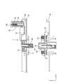
- the connector 1 of this embodiment is arranged in parallel in the Y-axis direction between the inverter side and the motor side, and connects between the two. Specifically, as shown in FIGS. 3 and 7, each connector 1 is arranged between an inverter-side terminal 82 and a motor-side terminal 92, which will be described later, and serves as a relay terminal that electrically connects the two. .
- the inverter-side terminal 82 is a male terminal that extends from the inverter side that is electrically connected to the inverter, and supplies AC power supplied from the inverter side to the motor. As shown in FIGS. 3 and 7, the inverter side terminal 82 is held in the inverter side housing 80 with the lower side as the connection side. The inverter-side housing 80 opens downward and is disposed above the lower portion of the inverter case 10.
- an inverter side rib 12 projecting downward in a rib shape and an inverter side opening surrounded by the inverter side rib 12 are formed in a part of the lower portion of the inverter case 10. 14 is provided.
- a motor-side rib 22 that protrudes upward in a rib shape and a motor-side opening 24 surrounded by the motor-side rib 22 are provided in a part of the upper portion of the motor case 20.
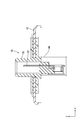
- the connector 1 includes an inverter-side terminal block 30, a motor-side terminal block 40, a first housing 50, a first terminal 52 held in the first housing 50, 2 housing 60, a second terminal 62 held in second housing 60, and a braided wire (an example of a conductive wire) 70 that connects between first terminal 52 and second terminal 62.
- the inverter side terminal block 30 is provided on the inverter side (upper side)
- the motor side terminal block 40 is provided on the motor side (lower side).
- the inverter-side terminal block 30 is a member that is smaller in size in plan view than the lower portion of the inverter case 10.
- the inverter side terminal block 30 is provided with a first attachment portion 32 and a second attachment portion 34.
- the 1st attachment part 32 has overlapped with the inverter side housing 80 in the up-down direction with the inverter side terminal block 30 as the lower side, and the second attachment part 34 will be described later with the inverter side terminal block 30 as the upper side. It overlaps with the motor-side housing 90 in the vertical direction.
- the first mounting portion 32 has a short cylindrical shape opening upward, and the surface of the lower opening edge is a first support surface 32A parallel to the XY plane.
- the second attachment portion 34 has a short cylindrical shape that opens downward, and an upper opening edge projects inward, and this projecting surface is a second support surface 34A that is parallel to the XY plane. Therefore, the first support surface 32A and the second support surface 34A are provided so as to be parallel to each other.
- the first housing 50 has a substantially cylindrical shape with the vertical direction as the cylinder axis direction. On the outer peripheral surface of the first housing 50 in the vicinity of the lower opening, there is provided a first projecting portion 51 projecting outward in parallel with the XY plane.
- a first terminal 52 On the upper opening side in the first housing 50, a first terminal 52, which is a female terminal, is held by a lance 54 that extends from the inner wall of the first housing 50 with its connection port facing upward. A part of the first terminal 52 opposite to the connection port extends to the vicinity of the lower opening along the inner wall of the first housing 50 and serves as a first connection portion 52A connected to a braided wire 70 described later. ing.
- the first housing 50 is attached to the first attachment portion 32 in such a manner that the first overhang portion 51 is addressed to the first support surface 32A of the first attachment portion 32, whereby the first support surface Floating supported with respect to 32A.
- the first housing 50 is slidably supported in the direction parallel to the first support surface 32A, that is, in the XY plane, by being floatingly supported on the first support surface 32A.
- the second housing 60 has substantially the same configuration as the first housing 50, and is attached to the second attachment portion 34 in an upside down posture with respect to the first housing 50. That is, the second housing 60 has a substantially cylindrical shape with the vertical direction as the cylinder axis direction, and a second tension projecting outward in parallel with the XY plane on the outer peripheral surface in the vicinity of the upper opening. A protruding portion 61 is provided.
- a second terminal 62 which is a female terminal, is held by a lance 64 extending from the inner wall of the second housing 60 on the lower opening side in the second housing 60 with its connection port facing downward. Yes.
- a part of the second terminal 62 opposite to the connection port extends to the vicinity of the upper opening along the inner wall of the second housing 60, and serves as a second connection portion 62A connected to a braided wire 70 described later. ing.
- the second overhanging portion 61 of the second housing 60 is addressed to the second support surface 34A of the second mounting portion 34. Further, an annular retainer member 72 is attached from the lower opening side of the second attachment portion 34 so that the second housing 60 is inserted inside the retainer member 72. Accordingly, the second housing 60 is attached to the second attachment portion 34 in such a manner that the second overhang portion 61 is sandwiched between the second support surface 34A and the retainer member 72, and the second support surface 34 Floating supported with respect to 34A.
- the second housing 60 is slidably supported in the direction parallel to the second support surface 34A, that is, in the XY plane, by being floatingly supported by the second support surface 34A.
- the braided wire 70 is a flexible conductive member and is slidable in the XY plane direction in the inverter side terminal block 30.
- the braided wire 70 is slidably arranged in the inverter-side terminal block 30 in each of the direction along the first support surface 32A and the direction along the second support surface 34A.
- the braided wire 70 is electrically connected to the first connection portion 52A of the first terminal 52 held at one end 70A in the first housing 50 and held at the other end 70B in the second housing 60.
- the second connection part 62 ⁇ / b> A of the second terminal 62 is electrically connected. Therefore, in the inverter side terminal block 30, the first terminal 52 and the second terminal 62 are electrically connected via the braided wire 70.
- the motor side terminal block 40 is arranged in a form to be placed on the upper portion of the motor case 20 as shown in FIGS. As shown in FIG. 7, the motor-side terminal block 40 is provided with a substantially plate-shaped main body portion 42 and a protruding portion 44 that protrudes vertically from a part of the main body portion 42.
- the motor-side terminal block 40 has a plate surface of the main body portion 42 placed on the motor-side rib 22 of the motor case 20 and a lower portion of the projecting portion 44 at the motor-side opening 24. In the inserted state, it is fixed to the motor case 20 by being fastened to the motor case 20 with a bolt B.
- a motor-side housing 90 that opens upward is provided on the upper portion of the protrusion 44 as shown in FIG.
- a motor side terminal 92 which is a male terminal is held with the upper side as a connection side.
- the motor side terminal 92 extends to the lower part of the motor side protruding portion 44 and is electrically connected to the motor, and supplies AC power converted by the inverter to the motor side.
- the connector 1 of the present embodiment has the above configuration, and the connection procedure will be described next.
- the main body of the motor side terminal block 40 is placed on the motor side rib 22 of the motor case 20 via the first seal member S1.
- the portion 42 is placed, and the lower side portion of the projecting portion 44 is inserted into the motor side opening 24 of the motor case 20 so that the motor side terminal block 40 is assembled to the motor case 20 and the space between the two is assembled. Fix it.
- the first seal member S ⁇ b> 1 is disposed between the main body portion 42 of the motor side terminal block 40 and the motor side rib 22. By doing so, the gap between the two is sealed. Thereby, it can prevent thru
- the first housing 50 is placed in the inverter side housing 80 from above the inverter side terminal block 30 with the first housing 50 and the second housing 60 attached in advance. Fit.
- the inverter-side terminal 82 and the first terminal 52 are male and female fitted in the vertical direction, and the two terminals are electrically connected.
- the lower surface of the inverter side terminal block 30 is directed to the lower inner wall of the inverter case 10, and the lower part of the second housing 60 is inserted into the inverter side opening 14 of the inverter case 10.
- the connector 1 is assembled
- the lower opening edge of the second mounting portion 34 coincides with the lower surface of the inverter-side terminal block 30 in the vertical direction. For this reason, when the connector 1 is assembled to the inverter case 10, the second mounting portion 34 does not interfere with the inverter case 10.
- the relative position in the XY plane direction between the inverter case 10 and the motor case 20 is determined.
- the inverter case 10 and the motor case 20 are each provided with a knock pin (not shown) and a bracket (not shown) on the other. By fitting these knock pins and brackets, the relative position in the XY plane direction between the inverter case 10 and the motor case 20 can be determined.
- the inverter side terminal block 30 assembled with the inverter case 10 is positioned between the inverter case 10 and the motor case 20, and then the motor side housing 90
- the second housing 60 is fitted into the bottom.
- the second terminal 62 and the motor side terminal 92 are male and female fitted in the vertical direction, and the two terminals are electrically connected.
- the second seal member S ⁇ b> 2 is disposed between the inverter side rib 12 and the main body 42 of the motor side terminal block 40. By doing so, seal between the two. Thereby, it is possible to prevent or suppress water or the like from entering between the inverter case 10 and the motor-side main body 42 (connection portion between the second terminal 62 and the motor-side terminal 92).
- the inverter-side terminal 82 and the motor-side terminal 92 are electrically connected via the connector 1, and AC power converted by the inverter is supplied to the motor.
- a downward force is applied to the motor side terminal block 40 due to the weight of the inverter side terminal block 30 itself. It is difficult for the motor-side terminal 92 to be disconnected in the vertical direction.
- both terminals 82 and 52 are caused due to component variations and assembly variations.
- the relative position between them may be displaced in the X-axis direction, the Y-axis direction, and the Z-axis direction.
- the inverter-side terminal 82 and the first terminal 52 are male-female fitted in a direction orthogonal to the first support surface 32A, that is, the Z-axis direction. By varying the degree, it is possible to absorb the positional deviation in the Z-axis direction.
- the first housing 50 in which the first terminal 52 is held is floatingly supported by the first support surface 32A, and the braided wire 70 connected to the first terminal 52 is the first support surface 32A. Since the first housing and the first terminal slide with the braided wire 70, the positional deviation in the X-axis direction and the Y-axis direction is possible. Can be absorbed.
- the motor side terminal 92 and the second terminal 62 are fitted, due to component variations and assembly variations, between the terminals 92 and 62. May shift in the X axis direction, the Y axis direction, and the Z axis direction.
- the motor-side terminal 92 and the second terminal 62 are male-female fitted in the direction orthogonal to the second support surface 34A, that is, the Z-axis direction. By varying the degree, it is possible to absorb the positional deviation in the Z-axis direction.
- the second housing 60 in which the second terminal 62 is held is floatingly supported by the second support surface 34A, and the braided wire 70 connected to the second terminal 62 is the second support surface 34A. Since the second housing 60 and the second terminal 62 slide together with the braided wire 70, the positions in the X-axis direction and the Y-axis direction are slidable in the direction along the X-Y plane. Misalignment can be absorbed.
- the X at the time of fitting in each of the fitting of the inverter side terminal 82 and the first terminal 52 and the fitting of the motor side terminal 92 and the second terminal 62 A positional shift in each of the axial direction, the Y-axis direction, and the Z-axis direction can be effectively absorbed.
- the relative position between the two terminals when the terminals are fitted to each other is Even if it is a position shift in each direction, between terminals can be satisfactorily fitted. As a result, the connection between the inverter and the motor can be facilitated.
- the braided wire 70 is disposed in the inverter side terminal block 30, and the first support surface 32 ⁇ / b> A and the second support surface 34 ⁇ / b> A are provided in parallel in the inverter side terminal block 30.
- the direction along the first support surface 32A and the direction along the second support surface 34A are the same direction, and therefore, in one plane direction (XY plane direction).
- the braided wire 70 may be slidably disposed only along the line, and the braided wire 70 can be easily disposed in the inverter-side terminal block 30.
- the inverter side terminal is a male terminal and the first terminal is a female terminal.
- the inverter side terminal is a female terminal, and the first terminal is a male terminal.
- mold terminal may be sufficient.
- the motor side terminal is a male terminal and the second terminal is a female terminal.
- the motor side terminal is a female terminal, and the second terminal is a male terminal.
- mold terminal may be sufficient.
- the braided wire is illustrated as an example of the conductive wire, but the configuration of the conductive wire is not limited.
Landscapes
- Engineering & Computer Science (AREA)
- Power Engineering (AREA)
- Transportation (AREA)
- Mechanical Engineering (AREA)
- Life Sciences & Earth Sciences (AREA)
- Sustainable Development (AREA)
- Sustainable Energy (AREA)
- Details Of Connecting Devices For Male And Female Coupling (AREA)
- Motor Or Generator Frames (AREA)
- Connector Housings Or Holding Contact Members (AREA)
- Inverter Devices (AREA)
Abstract
La présente invention concerne un connecteur équipé : d'un premier boîtier (50) supporté de manière flottante sur une première surface (32A) de support à l'intérieur d'une plaque (30) à bornes côté onduleur ; d'un second boîtier (60) supporté de manière flottante sur une seconde surface (34A) de support à l'intérieur de la plaque (30) à bornes côté onduleur ; d'une première borne (52) retenue à l'intérieur du premier boîtier (50), destinée à un appariement mâle-femelle avec une borne (82) côté onduleur dans une direction orthogonale à la première surface (32A) de support ; d'une seconde borne (62) retenue à l'intérieur du second boîtier (60), destinée à un appariement mâle-femelle dans une direction orthogonale à la seconde surface (34A) de support, avec une borne (92) côté moteur disposée sur une plaque (40) à bornes côté moteur ; et d'un fil tressé (70) connecté au niveau d'une extrémité à la première borne (52), connecté au niveau de l'autre extrémité à la seconde borne (62), et agencé coulissant dans une direction le long de la première surface (32A) de support et dans une direction le long de la seconde surface (34A) de support, respectivement.
Priority Applications (3)
| Application Number | Priority Date | Filing Date | Title |
|---|---|---|---|
| EP14870032.1A EP3082201B1 (fr) | 2013-12-13 | 2014-11-28 | Connecteur |
| US15/038,481 US9698528B2 (en) | 2013-12-13 | 2014-11-28 | Connector for directly connecting an inverter and a motor |
| CN201480065911.0A CN105814755B (zh) | 2013-12-13 | 2014-11-28 | 连接器 |
Applications Claiming Priority (2)
| Application Number | Priority Date | Filing Date | Title |
|---|---|---|---|
| JP2013257780A JP5967063B2 (ja) | 2013-12-13 | 2013-12-13 | コネクタ |
| JP2013-257780 | 2013-12-13 |
Publications (1)
| Publication Number | Publication Date |
|---|---|
| WO2015087717A1 true WO2015087717A1 (fr) | 2015-06-18 |
Family
ID=53371028
Family Applications (1)
| Application Number | Title | Priority Date | Filing Date |
|---|---|---|---|
| PCT/JP2014/081532 WO2015087717A1 (fr) | 2013-12-13 | 2014-11-28 | Connecteur |
Country Status (5)
| Country | Link |
|---|---|
| US (1) | US9698528B2 (fr) |
| EP (1) | EP3082201B1 (fr) |
| JP (1) | JP5967063B2 (fr) |
| CN (1) | CN105814755B (fr) |
| WO (1) | WO2015087717A1 (fr) |
Cited By (3)
| Publication number | Priority date | Publication date | Assignee | Title |
|---|---|---|---|---|
| CN107634379A (zh) * | 2016-07-19 | 2018-01-26 | 住友电装株式会社 | 连接器 |
| WO2021124491A1 (fr) * | 2019-12-18 | 2021-06-24 | トヨタ自動車株式会社 | Connecteur latéral de fil électrique |
| DE102018208334B4 (de) | 2017-06-02 | 2023-08-03 | Yazaki Corporation | Verbindungseinrichtungsmontagestruktur und anschlussstufe |
Families Citing this family (9)
| Publication number | Priority date | Publication date | Assignee | Title |
|---|---|---|---|---|
| CN106299781B (zh) * | 2016-08-10 | 2018-12-28 | 深圳市深台帏翔电子有限公司 | 连接器 |
| DE102017207215A1 (de) * | 2017-04-28 | 2018-10-31 | Zf Friedrichshafen Ag | Anschlusseinrichtung |
| JP6317844B1 (ja) * | 2017-05-30 | 2018-04-25 | イリソ電子工業株式会社 | コネクタ |
| JP6848722B2 (ja) * | 2017-06-27 | 2021-03-24 | 住友電装株式会社 | コネクタ及びコネクタの取付構造 |
| JP6822922B2 (ja) | 2017-08-14 | 2021-01-27 | トヨタ自動車株式会社 | 電子機器の車載構造 |
| BE1026231B1 (de) * | 2018-04-24 | 2019-11-25 | Phoenix Contact Gmbh & Co | Elektrischer verbinder |
| DE102020200584A1 (de) | 2020-01-20 | 2021-07-22 | Continental Teves Ag & Co. Ohg | Stecksystem zur elektrischen Verbindung von elektronischen Baugruppen und Druckbereitstellungseinrichtung mit einem Stecksystem |
| CN113745905B (zh) * | 2020-05-29 | 2024-03-29 | 庆虹电子(苏州)有限公司 | 连接器装置及连接器浮动模块 |
| JP2022150183A (ja) * | 2021-03-26 | 2022-10-07 | マツダ株式会社 | 電動車両の下部構造 |
Citations (5)
| Publication number | Priority date | Publication date | Assignee | Title |
|---|---|---|---|---|
| WO2011016272A1 (fr) * | 2009-08-03 | 2011-02-10 | 矢崎総業株式会社 | Connecteur |
| WO2011055806A1 (fr) * | 2009-11-06 | 2011-05-12 | 矢崎総業株式会社 | Bloc terminal inverseur pour carter de moteur |
| JP2011187224A (ja) | 2010-03-05 | 2011-09-22 | Yazaki Corp | モータケースに設置されたインバータ端子台 |
| WO2012056909A1 (fr) * | 2010-10-25 | 2012-05-03 | 矢崎総業株式会社 | Structure de connecteur pour connexion de dispositifs |
| WO2012137766A1 (fr) * | 2011-04-05 | 2012-10-11 | 株式会社オートネットワーク技術研究所 | Connecteur |
Family Cites Families (5)
| Publication number | Priority date | Publication date | Assignee | Title |
|---|---|---|---|---|
| JP3984579B2 (ja) * | 2003-09-16 | 2007-10-03 | 株式会社オートネットワーク技術研究所 | インバータ用コネクタ装置 |
| FR2897206B1 (fr) * | 2006-02-03 | 2008-03-21 | Mge Ups Systems Soc Par Action | Dispositif de branchement en parallele d'une pluralite d'appareils d'alimentation electrique |
| JP4665848B2 (ja) * | 2006-03-15 | 2011-04-06 | 日立電線株式会社 | コネクタ構造 |
| JP4840671B2 (ja) * | 2008-10-29 | 2011-12-21 | アイシン・エィ・ダブリュ株式会社 | 電気的接続構造 |
| DE102009029545A1 (de) * | 2009-09-17 | 2011-03-31 | Robert Bosch Gmbh | Steckverbindung |
-
2013
- 2013-12-13 JP JP2013257780A patent/JP5967063B2/ja not_active Expired - Fee Related
-
2014
- 2014-11-28 EP EP14870032.1A patent/EP3082201B1/fr not_active Not-in-force
- 2014-11-28 WO PCT/JP2014/081532 patent/WO2015087717A1/fr active Application Filing
- 2014-11-28 CN CN201480065911.0A patent/CN105814755B/zh not_active Expired - Fee Related
- 2014-11-28 US US15/038,481 patent/US9698528B2/en active Active
Patent Citations (5)
| Publication number | Priority date | Publication date | Assignee | Title |
|---|---|---|---|---|
| WO2011016272A1 (fr) * | 2009-08-03 | 2011-02-10 | 矢崎総業株式会社 | Connecteur |
| WO2011055806A1 (fr) * | 2009-11-06 | 2011-05-12 | 矢崎総業株式会社 | Bloc terminal inverseur pour carter de moteur |
| JP2011187224A (ja) | 2010-03-05 | 2011-09-22 | Yazaki Corp | モータケースに設置されたインバータ端子台 |
| WO2012056909A1 (fr) * | 2010-10-25 | 2012-05-03 | 矢崎総業株式会社 | Structure de connecteur pour connexion de dispositifs |
| WO2012137766A1 (fr) * | 2011-04-05 | 2012-10-11 | 株式会社オートネットワーク技術研究所 | Connecteur |
Cited By (5)
| Publication number | Priority date | Publication date | Assignee | Title |
|---|---|---|---|---|
| CN107634379A (zh) * | 2016-07-19 | 2018-01-26 | 住友电装株式会社 | 连接器 |
| DE102018208334B4 (de) | 2017-06-02 | 2023-08-03 | Yazaki Corporation | Verbindungseinrichtungsmontagestruktur und anschlussstufe |
| WO2021124491A1 (fr) * | 2019-12-18 | 2021-06-24 | トヨタ自動車株式会社 | Connecteur latéral de fil électrique |
| JPWO2021124491A1 (fr) * | 2019-12-18 | 2021-06-24 | ||
| JP7273189B2 (ja) | 2019-12-18 | 2023-05-12 | トヨタ自動車株式会社 | 電線側コネクタ |
Also Published As
| Publication number | Publication date |
|---|---|
| US9698528B2 (en) | 2017-07-04 |
| JP2015115251A (ja) | 2015-06-22 |
| EP3082201A4 (fr) | 2016-11-30 |
| CN105814755A (zh) | 2016-07-27 |
| US20160301160A1 (en) | 2016-10-13 |
| EP3082201A1 (fr) | 2016-10-19 |
| JP5967063B2 (ja) | 2016-08-10 |
| CN105814755B (zh) | 2018-02-13 |
| EP3082201B1 (fr) | 2019-11-27 |
Similar Documents
| Publication | Publication Date | Title |
|---|---|---|
| JP5967063B2 (ja) | コネクタ | |
| JP6247604B2 (ja) | 防水コネクタ | |
| JP5067199B2 (ja) | 車載用の電気接続箱 | |
| JP6225836B2 (ja) | コネクタ構造 | |
| JP5991260B2 (ja) | コネクタ及びワイヤハーネス | |
| JP5978106B2 (ja) | コネクタ間の接続構造 | |
| EP3089278B1 (fr) | Assemblage de connecteur flottant | |
| JP2014086349A (ja) | コネクタ | |
| CN103579870A (zh) | 连接器 | |
| CN104218336A (zh) | 端子板 | |
| CN104218338A (zh) | 端子板 | |
| US9525237B2 (en) | Connector | |
| CN104218335A (zh) | 端子板 | |
| JP6209997B2 (ja) | 車載電気機器 | |
| JP6052155B2 (ja) | コネクタ | |
| JP6520425B2 (ja) | 機器用弾性シールド部材 | |
| JP6499142B2 (ja) | 接続装置 | |
| JP2015115252A (ja) | コネクタ | |
| JP2021052512A (ja) | 電気接続箱 | |
| JP2019075904A (ja) | 電気接続箱 | |
| JP2017103155A (ja) | コネクタ | |
| JP2014235972A (ja) | 中継用コネクタユニット |
Legal Events
| Date | Code | Title | Description |
|---|---|---|---|
| 121 | Ep: the epo has been informed by wipo that ep was designated in this application |
Ref document number: 14870032 Country of ref document: EP Kind code of ref document: A1 |
|
| REEP | Request for entry into the european phase |
Ref document number: 2014870032 Country of ref document: EP |
|
| WWE | Wipo information: entry into national phase |
Ref document number: 2014870032 Country of ref document: EP |
|
| WWE | Wipo information: entry into national phase |
Ref document number: 15038481 Country of ref document: US |
|
| NENP | Non-entry into the national phase |
Ref country code: DE |