WO2015083508A1 - 石炭不活性化処理装置 - Google Patents
石炭不活性化処理装置 Download PDFInfo
- Publication number
- WO2015083508A1 WO2015083508A1 PCT/JP2014/079915 JP2014079915W WO2015083508A1 WO 2015083508 A1 WO2015083508 A1 WO 2015083508A1 JP 2014079915 W JP2014079915 W JP 2014079915W WO 2015083508 A1 WO2015083508 A1 WO 2015083508A1
- Authority
- WO
- WIPO (PCT)
- Prior art keywords
- coal
- feed pipe
- protrusion
- rotary kiln
- main body
- Prior art date
- Legal status (The legal status is an assumption and is not a legal conclusion. Google has not performed a legal analysis and makes no representation as to the accuracy of the status listed.)
- Ceased
Links
Images

Classifications
-
- C—CHEMISTRY; METALLURGY
- C10—PETROLEUM, GAS OR COKE INDUSTRIES; TECHNICAL GASES CONTAINING CARBON MONOXIDE; FUELS; LUBRICANTS; PEAT
- C10L—FUELS NOT OTHERWISE PROVIDED FOR; NATURAL GAS; SYNTHETIC NATURAL GAS OBTAINED BY PROCESSES NOT COVERED BY SUBCLASSES C10G OR C10K; LIQUIFIED PETROLEUM GAS; USE OF ADDITIVES TO FUELS OR FIRES; FIRE-LIGHTERS
- C10L5/00—Solid fuels
- C10L5/02—Solid fuels such as briquettes consisting mainly of carbonaceous materials of mineral or non-mineral origin
- C10L5/04—Raw material of mineral origin to be used; Pretreatment thereof
-
- C—CHEMISTRY; METALLURGY
- C10—PETROLEUM, GAS OR COKE INDUSTRIES; TECHNICAL GASES CONTAINING CARBON MONOXIDE; FUELS; LUBRICANTS; PEAT
- C10L—FUELS NOT OTHERWISE PROVIDED FOR; NATURAL GAS; SYNTHETIC NATURAL GAS OBTAINED BY PROCESSES NOT COVERED BY SUBCLASSES C10G OR C10K; LIQUIFIED PETROLEUM GAS; USE OF ADDITIVES TO FUELS OR FIRES; FIRE-LIGHTERS
- C10L9/00—Treating solid fuels to improve their combustion
- C10L9/02—Treating solid fuels to improve their combustion by chemical means
- C10L9/06—Treating solid fuels to improve their combustion by chemical means by oxidation
-
- C—CHEMISTRY; METALLURGY
- C10—PETROLEUM, GAS OR COKE INDUSTRIES; TECHNICAL GASES CONTAINING CARBON MONOXIDE; FUELS; LUBRICANTS; PEAT
- C10L—FUELS NOT OTHERWISE PROVIDED FOR; NATURAL GAS; SYNTHETIC NATURAL GAS OBTAINED BY PROCESSES NOT COVERED BY SUBCLASSES C10G OR C10K; LIQUIFIED PETROLEUM GAS; USE OF ADDITIVES TO FUELS OR FIRES; FIRE-LIGHTERS
- C10L9/00—Treating solid fuels to improve their combustion
- C10L9/08—Treating solid fuels to improve their combustion by heat treatments, e.g. calcining
-
- F—MECHANICAL ENGINEERING; LIGHTING; HEATING; WEAPONS; BLASTING
- F27—FURNACES; KILNS; OVENS; RETORTS
- F27B—FURNACES, KILNS, OVENS OR RETORTS IN GENERAL; OPEN SINTERING OR LIKE APPARATUS
- F27B7/00—Rotary-drum furnaces, i.e. horizontal or slightly inclined
- F27B7/06—Rotary-drum furnaces, i.e. horizontal or slightly inclined adapted for treating the charge in vacuum or special atmosphere
-
- F—MECHANICAL ENGINEERING; LIGHTING; HEATING; WEAPONS; BLASTING
- F27—FURNACES; KILNS; OVENS; RETORTS
- F27B—FURNACES, KILNS, OVENS OR RETORTS IN GENERAL; OPEN SINTERING OR LIKE APPARATUS
- F27B7/00—Rotary-drum furnaces, i.e. horizontal or slightly inclined
- F27B7/20—Details, accessories or equipment specially adapted for rotary-drum furnaces
-
- C—CHEMISTRY; METALLURGY
- C10—PETROLEUM, GAS OR COKE INDUSTRIES; TECHNICAL GASES CONTAINING CARBON MONOXIDE; FUELS; LUBRICANTS; PEAT
- C10L—FUELS NOT OTHERWISE PROVIDED FOR; NATURAL GAS; SYNTHETIC NATURAL GAS OBTAINED BY PROCESSES NOT COVERED BY SUBCLASSES C10G OR C10K; LIQUIFIED PETROLEUM GAS; USE OF ADDITIVES TO FUELS OR FIRES; FIRE-LIGHTERS
- C10L2290/00—Fuel preparation or upgrading, processes or apparatus therefore, comprising specific process steps or apparatus units
- C10L2290/06—Heat exchange, direct or indirect
-
- C—CHEMISTRY; METALLURGY
- C10—PETROLEUM, GAS OR COKE INDUSTRIES; TECHNICAL GASES CONTAINING CARBON MONOXIDE; FUELS; LUBRICANTS; PEAT
- C10L—FUELS NOT OTHERWISE PROVIDED FOR; NATURAL GAS; SYNTHETIC NATURAL GAS OBTAINED BY PROCESSES NOT COVERED BY SUBCLASSES C10G OR C10K; LIQUIFIED PETROLEUM GAS; USE OF ADDITIVES TO FUELS OR FIRES; FIRE-LIGHTERS
- C10L2290/00—Fuel preparation or upgrading, processes or apparatus therefore, comprising specific process steps or apparatus units
- C10L2290/14—Injection, e.g. in a reactor or a fuel stream during fuel production
- C10L2290/145—Injection, e.g. in a reactor or a fuel stream during fuel production of air
-
- C—CHEMISTRY; METALLURGY
- C10—PETROLEUM, GAS OR COKE INDUSTRIES; TECHNICAL GASES CONTAINING CARBON MONOXIDE; FUELS; LUBRICANTS; PEAT
- C10L—FUELS NOT OTHERWISE PROVIDED FOR; NATURAL GAS; SYNTHETIC NATURAL GAS OBTAINED BY PROCESSES NOT COVERED BY SUBCLASSES C10G OR C10K; LIQUIFIED PETROLEUM GAS; USE OF ADDITIVES TO FUELS OR FIRES; FIRE-LIGHTERS
- C10L2290/00—Fuel preparation or upgrading, processes or apparatus therefore, comprising specific process steps or apparatus units
- C10L2290/56—Specific details of the apparatus for preparation or upgrading of a fuel
Definitions
- the present invention relates to a coal deactivation treatment apparatus that performs deactivation treatment of coal with a treatment gas containing oxygen.
- Low-grade coal with high water content such as lignite and sub-bituminous coal has a low calorific value per unit weight, so it is dried and dry-distilled by heating, and in a low-oxygen atmosphere. By reforming so as to reduce the oxidation reaction activity, the reformed coal has an increased calorific value per unit weight while preventing spontaneous ignition.
- a coal inactivation treatment apparatus for inactivating dry distillation coal obtained by drying or carbonizing the above-described low-grade coal As a coal inactivation treatment apparatus for inactivating dry distillation coal obtained by drying or carbonizing the above-described low-grade coal, a rotary kiln to which dry distillation coal and process gas are supplied is provided, and the periphery thereof is provided in the rotary kiln.
- An apparatus having a plurality of feed pipes adjacent to each other in the direction through which cooling water flows is being studied.
- the above-described coal inactivation treatment apparatus rotates the rotary kiln and rotates the rotary kiln main body while cooling the dry-distilled coal with cooling water flowing through the feed pipe by rotating the rotary kiln and the plurality of feed pipes. While stirring, a plurality of feed pipes pass through a coal bed in which dry-distilled coal accumulates in a rotary kiln, lift the dry-distilled coal above the coal bed surface, and drop from above to the coal bed surface By stirring the carbonized carbon, the carbonized coal is inactivated by the processing gas. The agitation is repeated while the carbonized coal moves from the base end side to the tip end side of the rotary kiln, and the carbonized coal is gradually pulverized.
- the present invention has been made to solve the above-described problems, and can efficiently adsorb oxygen onto the surface of coal while preventing spontaneous combustion of coal. It aims at providing the coal inactivation processing apparatus which can be performed.
- the coal inactivation processing apparatus for solving the above-described problem is a coal inactivation processing apparatus that inactivates coal with a processing gas containing oxygen, in which the coal and the processing gas are contained inside.
- a kiln main body provided rotatably and provided rotatably with the kiln main body and extending in the longitudinal direction of the kiln main body, and a feed pipe through which cooling water flows.
- the coal inactivation processing apparatus according to the second invention that solves the above-described problem is the coal inactivation processing apparatus according to the first invention described above, wherein the protrusion is a radial section of the feed pipe. It is characterized in that it has a V-shape and the apex of the protrusion coincides with the locus of the central axis of the feed pipe.
- a coal inactivation processing apparatus that solves the above-described problem is the coal inactivation processing apparatus according to the first or second aspect of the invention described above, wherein the protrusion is formed of the protrusion.
- a coal inactivation processing apparatus that solves the above-described problem is the coal inactivation processing apparatus according to any one of the first to third aspects of the invention described above, and is the apex of the protrusion. And the center axis of the feed pipe is not more than twice the radius of the feed pipe.
- the outer periphery of the feed pipe is provided with a hat-shaped projection provided so as to project in the rotation direction of the feed pipe, and the feed pipe and the projection are
- the kiln body is arranged to pass through a coal layer in which the coal is deposited in the kiln body, while cooling the coal with cooling water circulating in the feed pipe, While stirring the coal by rotation, a predetermined amount of coal is lifted above the surface of the coal bed in the kiln body by the feed pipe and the protrusion, and dropped from above to stir the coal.
- the contact opportunity can be made suitable. Thereby, adsorption
- the overall length of the kiln main body can be shortened compared to the case where no protrusion is provided on the feed pipe, and the apparatus can be downsized.
- a coal deactivation treatment apparatus 100 that deactivates dry-distilled coal 1 has a hopper 101 that receives dry-distilled coal 1, and a base end side that communicates with a delivery port of the hopper 101. And a screw feeder 102 that is a rotary conveying means that rotates and conveys the coal 1 in the hopper 101 from one end side (base end side) to the other end side (tip end side).
- the distal end side of the screw feeder 102 communicates with the proximal end side of a cylindrical rotary kiln main body (kiln main body) 103.
- the base end side of the rotary kiln main body 103 is in communication with the base end side casing 111 via the sealing device 108.
- a gas receiving port 111 a for introducing the processing gas 13 is provided at the upper part of the base end side casing 111.
- the gas inlet 111a is connected to the distal end side of the processing gas supply pipe 121 that supplies the processing gas 13.
- a blower 127 and a heating device 128 are provided in the middle of the processing gas supply pipe 121.
- the distal end side of the air supply pipe 122 that supplies the air 11 and the distal end side of the nitrogen supply pipe 123 that supplies the nitrogen gas 12 are connected to the proximal end side of the processing gas supply pipe 121.
- the base end side of the air supply pipe 122 is open to the atmosphere.
- the base end side of the nitrogen supply pipe 123 is connected to a nitrogen supply source 124 such as a nitrogen gas tank.
- flow control valves 125 and 126 are provided, respectively.
- the distal end side of the rotary kiln main body 103 communicates with the distal end side casing 112 via seal devices 109a and 109b.
- a gas discharge port 112 a for discharging the used processing gas 14 is provided in the upper part of the front end side casing 112.
- the base end side of the processing gas discharge pipe 131 that discharges the used processing gas 14 is connected to the gas discharge port 112a.
- a temperature sensor 131 a is provided in the middle of the processing gas discharge pipe 131.
- a shooter 112b that drops and discharges the deactivated coal (modified coal) 3 is provided at the lower portion of the front end side casing 112.
- An annular ridge 104 is provided on the distal end side and the proximal end side of the outer peripheral portion of the rotary kiln main body 103, and the ridge 104 is supported by a roller 105.
- a gear 106 that meshes with the gear 107 a of the driving electric motor 107 is provided on the outer peripheral portion of the rotary kiln main body 103. Therefore, when the gear 107a of the driving motor 107 is rotated, the rotary kiln main body 103 is rotated.
- the coal inactivation processing apparatus 100 described above further includes a cooling device 140.
- the cooling device 140 includes a bearing 145 fixed to the side wall portion 103 a on the distal end side of the rotary kiln main body 103.
- the cooling device 140 includes a cooling water supply header 141 that is provided on the bearing 145 and to which the cooling water 21 is supplied from outside the system.
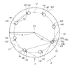
- a plurality of, for example, eight (see FIG. 2) feed pipes 142 (for example, double pipes) for feeding the coolant 21 are connected to the coolant feed header 141.
- the cooling device 140 includes a cooling water discharge header 146 that discharges the used cooling water 22 circulated through the supply pipe 142 to the outside of the system.
- the plurality of feed pipes 142 are arranged in the rotary kiln main body 103 adjacent to each other at equal intervals in the circumferential direction of the rotary kiln main body 103.
- the plurality of feed pipes 142 is a coal layer formed by depositing coal 2 even when the filling rate of coal 2 into the rotary kiln body 103 is, for example, 10% to 15% when the rotary kiln body 103 rotates. It arrange
- the plurality of feed pipes 142 extend in the rotary kiln main body 103 in parallel to the central axis C1 of the rotary kiln main body 103, and extend from the distal end side to the proximal end side of the rotary kiln main body 103. .
- the temperature is adjusted so that the coal 2 does not spontaneously ignite by the cooling water 21 flowing in the feed pipe 142. Is done.
- the plurality of feed pipes 142 are disposed so as to penetrate the side wall 103a of the rotary kiln main body 103.
- the plurality of feed pipes 142 are supported by support tools (not shown) arranged at a plurality of locations in the longitudinal direction. As a result, the plurality of feed pipes 142 rotate around the central axis C ⁇ b> 1 of the rotary kiln body 103 together with the rotary kiln body 103 as the rotary kiln body 103 rotates.
- A indicates the rotational direction of the rotary kiln body 103.
- L1 indicates a trajectory through which the central axis C2 of the plurality of supply pipes 142 passes, and L2 indicates a tangent to the trajectory L1.
- L3 indicates a bisector of a protrusion 143 to be described later.
- L4 and L5 indicate tangent lines of the feed pipe 142 passing through the apex 143c of the protrusion 143.
- L11 indicates an auxiliary line passing through the contact point P1 between the feed pipe 142 and the tangent line L5 and the contact point P2 between the feed pipe 142 and the tangent line L4.
- L12 and L13 indicate auxiliary lines passing through the central axis C2 of the feed pipe 142 and the contacts P1 and P2, respectively.
- ⁇ is an acute angle formed by the bisector L3 and the tangent line L5 (inner plane portion 143a of the hat), and indicates the angle (hat angle) of the protrusion, and ⁇ is formed by the bisector L3 and the auxiliary line L12. It shows an acute angle.
- ⁇ represents an acute angle formed by the tangent line L5 and the auxiliary line L11.
- auxiliary lines L11, L12, and L13 form an isosceles triangle having the central axis C2 as an apex, and the auxiliary line L12 and the tangent line L5 form a right angle. Therefore, the angle ⁇ is the same size as the angle ⁇ .
- the feed pipe 142 has a perfect circle in its radial cross section.
- a protrusion 143 having a hat shape is provided on the outer peripheral portion of the feed pipe 142 so as to project in the rotation direction A of the feed pipe 142. More specifically, the protrusion 143 has a V shape in the radial cross section of the feed pipe 142. Similar to the feed pipe 142, the protrusion 143 is configured so that when the rotary kiln main body 103 rotates, even if the filling rate of the coal 2 into the rotary kiln main body 103 is, for example, 10% to 15%, It is arranged at a position that passes through the coal bed that is deposited.
- the protruding portion 143 includes an inner flat surface portion 143a positioned on the central axis C1 side of the rotary kiln main body 103 and an outer flat surface portion 143b positioned on the outer peripheral surface side of the rotary kiln main body 103.
- the distal end side of the inner plane portion 143a and the outer plane portion 143b is connected.
- the apex 143c of the protrusion 143 is positioned at a position that coincides with the locus of the central axis C2 of the feed pipe 142.
- the amount of coal lifted above the coal bed surface 2a by the feed pipe 142 and the protrusion 143 can be reduced as compared with the case where there is no hat-shaped protrusion, so that a suitable state can be obtained.
- the contact opportunity between the coal 2 and the processing gas 13 by stirring is in a suitable state, and the efficiency of the inactivation processing of the coal 2 can be improved.
- the inner plane portion 143a and the outer plane portion 143b are arranged symmetrically on a plane passing through the tip portion 143c of the protrusion 143 and the central axis C2. That is, the protrusion 143 has a shape that is plane-symmetric. Further, a corner portion ⁇ formed by a straight line L11 connecting the intersections P2, P1 of the two tangents L4, L5 of the feed pipe 142 passing through the apex 143c of the projection 143 and the feed pipe 142 and one of the tangent lines L5. However, it is larger than the angle of repose.
- the distance D2 between the tip 143c of the protrusion 143 and the central axis C2 of the feed pipe 142 is preferably less than or equal to twice the radius of the feed pipe 142, and more preferably less than or equal to one. This is because when the distance D2 exceeds the upper limit value, the heat transfer area between the cooling water 21 and the coal 2 in the feed pipe 142 decreases, the heat exchange rate decreases, and the rotary kiln main body 103 This is because a large number of space portions are formed between the projection 143 and the feed pipe 142, and the amount of treated coal is reduced.
- feed pipe 142 and the protrusion 143 it is possible to use one made of a material having no reactivity with the coal 2 and having heat resistance, for example, steel.
- the radius r2 of the feed pipe 142 and the distance D1 between the central axis C1 of the rotary kiln main body 103 and the central axis C2 of the feed pipe 142 are expressed by the following relational expression (1 ) Is more preferable.
- the distance D3 between the adjacent feed pipes 142 and 142 satisfies the following expression (2).
- the nitrogen supply source 124, the base end side casing 111, the gas receiving port 111a, and the like constitute processing gas supply means.
- the cooling water feed header 141, the feed pipe 142, the projection 143, the bearing 145, the cooling water discharge header 146, and the like constitute the cooling device 140 that forms a cooling means.
- the ridge 104, the roller 105, the gear 106, the drive motor 107, the gear 107a, and the like constitute a rotating means.
- the hopper 101, the screw feeder 102, and the like constitute coal supply means.
- the shooter 112b and the like of the front end side casing 112 constitute coal discharging means.
- the front end side casing 112, the gas discharge port 112a, the processing gas discharge pipe 131, and the like constitute processing gas discharge means.
- Each means, the rotary kiln main body 103, the sealing devices 108, 109a, 109b, etc. constitute the coal inactivation processing device 100.
- the coal 1 When the coal 1 is supplied to the hopper 101, the coal 1 is conveyed into the rotary kiln main body 103 by the screw feeder 102.
- the air 11 and the nitrogen gas 12 are supplied to the processing gas supply pipe 121 via the air supply pipe 122 and the nitrogen supply pipe 123 by controlling the opening degree of the flow rate adjusting valves 125 and 126. Supplied.
- the air 11 and the nitrogen gas 12 are mixed to become the processing gas 13 (for example, the oxygen concentration is about 5 to 10%).
- the processing gas 13 is heated by the heating device 128 based on the temperature data of the used processing gas 14 obtained by the temperature sensor 131a, and adjusted to be 40 ° C. to 200 ° C. in the rotary kiln main body 103.
- a gas supply pipe 121 supplies the rotary kiln main body 103 through the gas receiving port 111a.
- the rotary kiln main body 103 rotates when the gear 107 a of the driving motor 107 rotates and is transmitted via the gear 106.
- the coal 2 conveyed into the rotary kiln main body 103 moves from the proximal end side to the distal end side of the rotary kiln main body 103 while being stirred.
- the coal 2 in the rotary kiln main body 103 adsorbs the oxygen of the processing gas 13 supplied into the rotary kiln main body 103.
- the inactivated coal (reformed coal) 3 is obtained by oxygen adsorption, and is carried out of the system via the shooter 112b.
- the coal 2 in the rotary kiln main body 103 generates heat by adsorbing oxygen in the processing gas 13, the coal 2 is adjusted to a temperature at which the coal 2 does not spontaneously ignite by the cooling water 21 flowing through the feed pipe 142.
- the used processing gas (about 50 ° C. to 70 ° C.) 14 used for the inactivation processing of the coal 2 in the rotary kiln main body 103 circulates in the same direction as the transport direction of the coal 2, and the rotary kiln main body 103
- the gas flows from the gas discharge port 112 a of the front end side casing 112 provided on the front end side to the process gas discharge pipe 131 and is discharged out of the system through the process gas discharge pipe 131.
- the rotary kiln main body 103 rotates with the rotary kiln main body 103 around the central axis C ⁇ b> 1 of the rotary kiln main body 103, and the rotary kiln main body 103 rotates.
- a plurality of feed pipes 142 are provided in the rotary kiln body 103 so as to pass through the coal bed formed by depositing the coal 2 supplied into the main body 103, and the projections 143 are provided on the feed pipes 142.
- it operates as follows.
- the outer periphery of the feed pipe 142 includes the protrusion 143 provided to project in the rotation direction A of the feed pipe 142, and the feed pipe 142 and the protrusion 143 are arranged so as to pass through a coal bed in which the coal 2 is deposited in the rotary kiln main body 103 when the rotary kiln main body 103 rotates, and thereby circulate in the feed pipe 142.
- the coal 2 While the coal 2 is being cooled by the cooling water 21 to be stirred, the coal 2 is agitated by the rotation of the rotary kiln main body 103, and a predetermined amount of the coal 2 is fed into the coal layer in the rotary kiln main body 103 by the feed pipe 142 and the protrusion 143.
- the coal 2 is stirred by being lifted upward from the surface 2a and dropped from above, and the contact opportunity between the coal 2 and the processing gas 13 can be made suitable. Thereby, adsorption
- the overall length of the rotary kiln main body 103 can be shortened compared to the case where no hat-shaped protrusion is provided on the feed pipe, and the apparatus can be downsized.
- the shape of the protrusion 143 provided in each of the plurality of supply pipes 142 is not limited to one type, and may be two or more types.
- the coal inactivation processing apparatus 100 including the eight supply pipes 142 has been described.
- the number of the supply pipes is not limited to eight, and seven or less or nine or more supply pipes are used. It is also possible to provide a coal inactivation treatment apparatus.
- 1,2,3 coal 11 air, 12 nitrogen gas, 13,14 treatment gas, 21,22 cooling water, 100 coal deactivation treatment device, 101 hopper, 102 screw feeder, 103 rotary kiln body (kiln body), 104 ridges, 105 rollers, 106 gears, 107 driving motors, 107a gears, 108 sealing devices, 109a and 109b sealing devices, 111 proximal casings, 111a gas inlets, 112 distal casings, 112a gas outlets, 112b shooter, 121 processing gas supply pipe, 122 air supply pipe, 123 nitrogen supply pipe, 124 nitrogen supply source, 125, 126 flow control valve, 127 blower, 128 heating device, 131 processing gas discharge pipe, 131a temperature sensor, 140 cooling Equipment, 141 Cooling water feed header, 142 Feed pipe, 143 Protrusion, 143a Inner plane, 143b Outer plane, 143c Apex, 145 bearing, 146 Coolant discharge header, A Rotary direction of rotary kiln
Landscapes
- Chemical & Material Sciences (AREA)
- Engineering & Computer Science (AREA)
- Organic Chemistry (AREA)
- Oil, Petroleum & Natural Gas (AREA)
- Geology (AREA)
- Geochemistry & Mineralogy (AREA)
- General Life Sciences & Earth Sciences (AREA)
- Environmental & Geological Engineering (AREA)
- Life Sciences & Earth Sciences (AREA)
- Mechanical Engineering (AREA)
- General Engineering & Computer Science (AREA)
- Combustion & Propulsion (AREA)
- Chemical Kinetics & Catalysis (AREA)
- General Chemical & Material Sciences (AREA)
- Thermal Sciences (AREA)
- Physics & Mathematics (AREA)
- Muffle Furnaces And Rotary Kilns (AREA)
- Solid Fuels And Fuel-Associated Substances (AREA)
- Incineration Of Waste (AREA)
Abstract
Description
図2において、Aはロータリキルン本体103の回転方向を示している。L1は、複数の送給管142の中心軸C2が通る軌跡を示し、L2は、前記軌跡L1の接線を示している。図2および図3において、L3は、後述する突起部143の二等分線を示している。図3において、L4,L5は、突起部143の頂点143cを通る送給管142の接線を示している。L11は、送給管142と接線L5の接点P1と、送給管142と接線L4の接点P2を通る補助線を示している。L12,L13は、送給管142の中心軸C2と接点P1,P2を通る補助線をそれぞれ示している。αは、二等分線L3と接線L5(ハットの内側平面部143a)でなす鋭角であり、突起部の角度(ハット角)を示し、βは二等分線L3と補助線L12とでなす鋭角を示している。θは接線L5と補助線L11でなす鋭角を示している。なお、補助線L11,L12,L13が中心軸C2を頂点とする二等辺三角形をなし、補助線L12と接線L5とで直角をなすことから、角βは、角θと同じ大きさとなる。
なお、複数の送給管142のそれぞれに設けられた突起部143の形状は1種類に限らず、2種類以上とすることも可能である。
Claims (4)
- 酸素を含有する処理ガスで石炭の不活性化を行う石炭不活性化処理装置において、
前記石炭および前記処理ガスが内部に供給され、回転可能に設けられたキルン本体と、
前記キルン本体と共に回転可能に設けられると共に、前記キルン本体の長手方向に延在して設けられ、内部を冷却水が流通する送給管と、
前記送給管の外周部に当該送給管の回転方向へ突出して設けられ当該送給管の径断面にてハット形をなす突起部とを備え、
前記送給管および前記突起部は、前記キルン本体が回転したときに当該キルン本体内にて前記石炭が堆積してなる石炭層を通過するように配置される
ことを特徴とする石炭不活性化処理装置。 - 請求項1に記載された石炭不活性化処理装置であって、
前記突起部は、前記送給管の径断面にてV字状をなし、
前記突起部の頂点は、前記送給管の中心軸の軌跡と一致する
ことを特徴とする石炭不活性化処理装置。 - 請求項1または請求項2に記載された石炭不活性化処理装置であって、
前記突起部は、当該突起部の頂点および前記送給管の中心軸を通る面で対称となる形状であり、
前記突起部の頂点を通る前記送給管の二つの接線の当該送給管との交点同士を結ぶ直線と、前記接線の一方とでなす角部が、安息角よりも大きい
ことを特徴とする石炭不活性化処理装置。 - 請求項1乃至請求項3の何れか一項に記載された石炭不活性化処理装置であって、
前記突起部の頂点と前記送給管の中心軸との距離は、前記送給管の半径の2倍以下である
ことを特徴とする石炭不活性化処理装置。
Priority Applications (4)
| Application Number | Priority Date | Filing Date | Title |
|---|---|---|---|
| AU2014358470A AU2014358470B2 (en) | 2013-12-06 | 2014-11-12 | Coal deactivation processing device |
| US15/037,807 US20160289582A1 (en) | 2013-12-06 | 2014-11-12 | Coal deactivation processing device |
| DE112014005551.4T DE112014005551T5 (de) | 2013-12-06 | 2014-11-12 | Vorrichtung zur Kohledeaktivierungsverarbeitung |
| CN201480064758.XA CN105793657B (zh) | 2013-12-06 | 2014-11-12 | 煤去活化处理装置 |
Applications Claiming Priority (2)
| Application Number | Priority Date | Filing Date | Title |
|---|---|---|---|
| JP2013252744A JP6226422B2 (ja) | 2013-12-06 | 2013-12-06 | 石炭不活性化処理装置 |
| JP2013-252744 | 2013-12-06 |
Publications (1)
| Publication Number | Publication Date |
|---|---|
| WO2015083508A1 true WO2015083508A1 (ja) | 2015-06-11 |
Family
ID=53273278
Family Applications (1)
| Application Number | Title | Priority Date | Filing Date |
|---|---|---|---|
| PCT/JP2014/079915 Ceased WO2015083508A1 (ja) | 2013-12-06 | 2014-11-12 | 石炭不活性化処理装置 |
Country Status (6)
| Country | Link |
|---|---|
| US (1) | US20160289582A1 (ja) |
| JP (1) | JP6226422B2 (ja) |
| CN (1) | CN105793657B (ja) |
| AU (1) | AU2014358470B2 (ja) |
| DE (1) | DE112014005551T5 (ja) |
| WO (1) | WO2015083508A1 (ja) |
Citations (4)
| Publication number | Priority date | Publication date | Assignee | Title |
|---|---|---|---|---|
| JPH11310785A (ja) * | 1998-04-30 | 1999-11-09 | Mitsubishi Heavy Ind Ltd | 石炭改質方法及びその装置 |
| JP2002130629A (ja) * | 2000-10-26 | 2002-05-09 | Chisaki:Kk | 可燃原料の横型回転加熱処理装置及び加熱処理方法 |
| JP2012026632A (ja) * | 2010-07-22 | 2012-02-09 | Tsukishima Kikai Co Ltd | 被処理物の乾燥分級方法 |
| JP2013189554A (ja) * | 2012-03-14 | 2013-09-26 | Mitsubishi Heavy Ind Ltd | 石炭乾留装置 |
Family Cites Families (9)
| Publication number | Priority date | Publication date | Assignee | Title |
|---|---|---|---|---|
| US3208512A (en) * | 1963-07-24 | 1965-09-28 | Dravo Corp | Heat exchanger for rotary kiln and the like |
| US3765102A (en) * | 1972-09-21 | 1973-10-16 | Patterson Kelley Co | Rotary apparatus for treating particulate material |
| CA1285515C (en) * | 1985-11-20 | 1991-07-02 | Gerhard J.A. Kennepohl | Method for passivating particulate coal |
| JP5084154B2 (ja) * | 2006-03-06 | 2012-11-28 | 中国電力株式会社 | 石炭ミルの火災予防方法及びその装置 |
| JP4727547B2 (ja) * | 2006-10-11 | 2011-07-20 | 三井金属アクト株式会社 | 車両用ウインドウレギュレータ装置 |
| JP4757772B2 (ja) * | 2006-10-30 | 2011-08-24 | 新日本製鐵株式会社 | 間隔保持部を備えたハット形鋼矢板およびその積み重ね方法 |
| JP2010094698A (ja) * | 2008-10-15 | 2010-04-30 | Toyota Motor Corp | 高強度部材製造方法、高強度部材製造方法に用いられる熱間プレス成形型及び高強度部品製造方法における中間成形体 |
| JP5412418B2 (ja) * | 2010-12-17 | 2014-02-12 | 三菱重工業株式会社 | 石炭不活化処理装置 |
| JP6147679B2 (ja) * | 2014-01-27 | 2017-06-14 | 三菱重工業株式会社 | 石炭乾留装置 |
-
2013
- 2013-12-06 JP JP2013252744A patent/JP6226422B2/ja not_active Expired - Fee Related
-
2014
- 2014-11-12 WO PCT/JP2014/079915 patent/WO2015083508A1/ja not_active Ceased
- 2014-11-12 AU AU2014358470A patent/AU2014358470B2/en not_active Ceased
- 2014-11-12 US US15/037,807 patent/US20160289582A1/en not_active Abandoned
- 2014-11-12 DE DE112014005551.4T patent/DE112014005551T5/de not_active Withdrawn
- 2014-11-12 CN CN201480064758.XA patent/CN105793657B/zh not_active Expired - Fee Related
Patent Citations (4)
| Publication number | Priority date | Publication date | Assignee | Title |
|---|---|---|---|---|
| JPH11310785A (ja) * | 1998-04-30 | 1999-11-09 | Mitsubishi Heavy Ind Ltd | 石炭改質方法及びその装置 |
| JP2002130629A (ja) * | 2000-10-26 | 2002-05-09 | Chisaki:Kk | 可燃原料の横型回転加熱処理装置及び加熱処理方法 |
| JP2012026632A (ja) * | 2010-07-22 | 2012-02-09 | Tsukishima Kikai Co Ltd | 被処理物の乾燥分級方法 |
| JP2013189554A (ja) * | 2012-03-14 | 2013-09-26 | Mitsubishi Heavy Ind Ltd | 石炭乾留装置 |
Also Published As
| Publication number | Publication date |
|---|---|
| US20160289582A1 (en) | 2016-10-06 |
| JP2015111015A (ja) | 2015-06-18 |
| AU2014358470B2 (en) | 2017-03-16 |
| AU2014358470A1 (en) | 2016-06-16 |
| JP6226422B2 (ja) | 2017-11-08 |
| CN105793657A (zh) | 2016-07-20 |
| CN105793657B (zh) | 2017-05-31 |
| DE112014005551T5 (de) | 2016-09-29 |
Similar Documents
| Publication | Publication Date | Title |
|---|---|---|
| TWI596311B (zh) | Indirect heated rotary dryer | |
| US8985313B2 (en) | Screw conveyor | |
| JP6245743B2 (ja) | 石炭不活性化処理装置 | |
| JP6188230B2 (ja) | 不活性化処理装置 | |
| JP5193322B2 (ja) | 間接加熱式乾燥機 | |
| CN103776244B (zh) | 滚筒烘干机 | |
| CN103438433B (zh) | 圆柱式送料系统的生物质颗粒燃烧机 | |
| JP6226422B2 (ja) | 石炭不活性化処理装置 | |
| CN105855273B (zh) | 用于保护气氛下加热处理物料的连续输送装置 | |
| KR101718502B1 (ko) | 로타리 킬른형 유동층 반응기 | |
| CN102875002A (zh) | 一种污泥干燥装置以及污泥处理系统 | |
| CN109622587A (zh) | 一种带有内管束的外热回转式有机污染土壤热脱附装置 | |
| CN118936001A (zh) | 干燥装置及干燥方法 | |
| CN205684468U (zh) | 用于保护气氛下加热处理物料的连续输送装置 | |
| CN201411369Y (zh) | 活性炭卧式转炉 | |
| CN112299415A (zh) | 一种活性炭生产装置及其炭化活化一体炉 | |
| RU2113671C1 (ru) | Печь для термической обработки углеродсодержащих материалов | |
| CN220892784U (zh) | 一种兰炭干燥装置 | |
| CN211373157U (zh) | 一种用于火电厂炉渣冷却及石膏干燥的一体化设备 | |
| CN115493391A (zh) | 一种对流螺旋式颗粒物料烘干装置 | |
| CN202481703U (zh) | 一种新型绞龙 | |
| WO2016024421A1 (ja) | 改質装置 | |
| CN106111009B (zh) | 一种有机无机肥料制粒机 | |
| CN218973216U (zh) | 一种连续还原碳化炉 | |
| CN214399065U (zh) | 消石灰及活性炭喷射装置的消石灰定量给料盘 |
Legal Events
| Date | Code | Title | Description |
|---|---|---|---|
| 121 | Ep: the epo has been informed by wipo that ep was designated in this application |
Ref document number: 14867013 Country of ref document: EP Kind code of ref document: A1 |
|
| WWE | Wipo information: entry into national phase |
Ref document number: 15037807 Country of ref document: US |
|
| WWE | Wipo information: entry into national phase |
Ref document number: IDP00201603572 Country of ref document: ID |
|
| WWE | Wipo information: entry into national phase |
Ref document number: 112014005551 Country of ref document: DE |
|
| ENP | Entry into the national phase |
Ref document number: 2014358470 Country of ref document: AU Date of ref document: 20141112 Kind code of ref document: A |
|
| 122 | Ep: pct application non-entry in european phase |
Ref document number: 14867013 Country of ref document: EP Kind code of ref document: A1 |