WO2015080187A1 - ドアチェック装置 - Google Patents
ドアチェック装置 Download PDFInfo
- Publication number
- WO2015080187A1 WO2015080187A1 PCT/JP2014/081328 JP2014081328W WO2015080187A1 WO 2015080187 A1 WO2015080187 A1 WO 2015080187A1 JP 2014081328 W JP2014081328 W JP 2014081328W WO 2015080187 A1 WO2015080187 A1 WO 2015080187A1
- Authority
- WO
- WIPO (PCT)
- Prior art keywords
- opening
- valve body
- magnetic force
- fluid
- valve
- Prior art date
- Legal status (The legal status is an assumption and is not a legal conclusion. Google has not performed a legal analysis and makes no representation as to the accuracy of the status listed.)
- Ceased
Links
Images












Classifications
-
- E—FIXED CONSTRUCTIONS
- E05—LOCKS; KEYS; WINDOW OR DOOR FITTINGS; SAFES
- E05C—BOLTS OR FASTENING DEVICES FOR WINGS, SPECIALLY FOR DOORS OR WINDOWS
- E05C17/00—Devices for holding wings open; Devices for limiting opening of wings or for holding wings open by a movable member extending between frame and wing; Braking devices, stops or buffers, combined therewith
- E05C17/02—Devices for holding wings open; Devices for limiting opening of wings or for holding wings open by a movable member extending between frame and wing; Braking devices, stops or buffers, combined therewith by mechanical means
- E05C17/04—Devices for holding wings open; Devices for limiting opening of wings or for holding wings open by a movable member extending between frame and wing; Braking devices, stops or buffers, combined therewith by mechanical means with a movable bar or equivalent member extending between frame and wing
- E05C17/12—Devices for holding wings open; Devices for limiting opening of wings or for holding wings open by a movable member extending between frame and wing; Braking devices, stops or buffers, combined therewith by mechanical means with a movable bar or equivalent member extending between frame and wing consisting of a single rod
- E05C17/20—Devices for holding wings open; Devices for limiting opening of wings or for holding wings open by a movable member extending between frame and wing; Braking devices, stops or buffers, combined therewith by mechanical means with a movable bar or equivalent member extending between frame and wing consisting of a single rod sliding through a guide
- E05C17/203—Devices for holding wings open; Devices for limiting opening of wings or for holding wings open by a movable member extending between frame and wing; Braking devices, stops or buffers, combined therewith by mechanical means with a movable bar or equivalent member extending between frame and wing consisting of a single rod sliding through a guide concealed, e.g. for vehicles
-
- E—FIXED CONSTRUCTIONS
- E05—LOCKS; KEYS; WINDOW OR DOOR FITTINGS; SAFES
- E05C—BOLTS OR FASTENING DEVICES FOR WINGS, SPECIALLY FOR DOORS OR WINDOWS
- E05C17/00—Devices for holding wings open; Devices for limiting opening of wings or for holding wings open by a movable member extending between frame and wing; Braking devices, stops or buffers, combined therewith
- E05C17/58—Devices for holding wings open; Devices for limiting opening of wings or for holding wings open by a movable member extending between frame and wing; Braking devices, stops or buffers, combined therewith operated or controlled from a distance, e.g. pneumatically
Definitions
- the present invention relates to a door check device.
- the door check device is configured to generate a resistance force to the door opening / closing operation (hereinafter, this force is referred to as a holding force).
- the door is opened and closed by inputting an operation force stronger than the holding force (hereinafter referred to as an opening / closing operation force) to the door.
- the door check device is mounted on a vehicle, for example.
- the door check device is provided between a vehicle body having an opening for passengers to get on and off and a vehicle door attached to the vehicle body so that the opening can be opened and closed.
- a general door check device is configured to generate a large holding force when the vehicle door is opened at a predetermined opening, and a holding force generated when the vehicle door is opened at any other opening is small.
- the door check device is configured so that a large holding force is generated when the opening degree of the vehicle door is 30 ° and 60 °.
- the optimum opening for generating a large holding force differs depending on the physique of the occupant and the surrounding environment of the vehicle (for example, the distance between adjacent vehicles). Therefore, there is a need for a door check device that can generate a large holding force at an arbitrary opening position where the user stops the opening and closing operation of the vehicle door.
- Patent Document 1 discloses a door check device (fixing device) capable of generating a large holding force when the opening / closing operation of a vehicle door is stopped at an arbitrary opening position.
- This door check device includes a cylinder filled with fluid, a rod inserted into the cylinder, a pair of springs interposed in the middle of the rod in the cylinder, and ends of the pair of springs, respectively.
- a valve seat provided with a pair of valve bodies provided and opposed to each other and an opening sealed by the valve body is provided.
- one of the valves By opening and closing the door with an opening / closing operation force larger than the holding force, one of the valves opens to form a fluid flow path in the cylinder.
- the vehicle door can be opened and closed relatively smoothly with a small opening / closing operation force once the valve is opened.
- the present invention has an object to provide a door check device configured to generate a large holding force at an arbitrary opening position with a simple configuration.
- the present invention is configured to be attached to a door capable of opening and closing an opening formed in a main body such as a vehicle body, in which a fluid is enclosed, and is formed into a cylindrical shape having one end face (2a) and the other end face (2b).
- a first through hole (21) on one end surface and a second through hole (22) on the other end surface are connected to a cylinder member (2), which is swingably connected to the main body at one end.
- a first rod portion (4) inserted through the first through hole into the cylinder member so as to be axially movable, and one end is a free end, and the second through hole is passed through the first through hole.
- the intermediate region and the first end region (R1) which is the region where the first rod portion is disposed in the cylinder member, are partitioned by contacting the inner wall of the cylinder member in the circumferential direction.
- a first seal member (15) that allows a fluid flow toward the first end region and blocks a fluid flow from the first end region toward the intermediate region; and the other end of the second rod portion within the cylinder member Is attached to the inner wall of the cylinder member over the circumferential direction.
- the intermediate region and the second end region (R2) which is the region where the second rod portion is disposed in the cylinder member, are partitioned, and the flow of fluid from the intermediate region toward the second end region is made.
- a second seal member (16) that allows and blocks a flow of fluid from the second end region toward the intermediate region, and communicates the intermediate region and the first end region in the first rod portion.
- a communication path (42) is formed, a first opening (41) that is an opening of the first communication path to the intermediate area is formed on the other end surface of the first rod part, and an intermediate area is formed in the second rod part.
- a second communication path (52) that communicates with the second end region is formed, and a second opening (51) that is an opening of the second communication path to the intermediate region is formed on the other end surface of the second rod portion.
- the first valve body receives the elastic force of the expansion and contraction member and receives the elastic force of the first opening.
- the second valve body is configured to be able to shut off the flow of fluid in the first communication path by engaging with the peripheral edge, and the second valve body receives the elastic force of the expansion and contraction member and engages with the peripheral edge of the second opening.
- a door check device configured to be able to block the flow of fluid in a communication path.
- the first valve body provided at one end of the expansion / contraction member receives the elastic force of the expansion / contraction member, thereby opening the first opening. Sealing is performed to block the flow of fluid in the first communication path.
- the 2nd valve body provided in the other end of the expansion-contraction member receives the elastic force of an expansion-contraction member, seals 2nd opening, and interrupt
- a door check device having a simple configuration using one telescopic member is provided by configuring the first valve body at one end of one telescopic member and the second valve body at the other end. can do. Further, the expansion / contraction member is immersed in the fluid in the cylinder member in the cylinder member, so that a special sealing structure for preventing the fluid in the cylinder member from flowing into the arrangement space of the expansion / contraction member is not required. . Therefore, it is possible to provide a door check device having a simple configuration in which a holding force is generated at an arbitrary opening position. Furthermore, according to the present invention, when the door is opened and closed, the rod member moves in the axial direction with respect to the cylinder member.
- the space in the cylinder member is divided into a first end region, an intermediate region, and a second end region by the first seal member and the second seal member, and the rod member is separated from the cylinder member.
- the fluid pressure difference between the fluid pressure in the intermediate region and the fluid pressure in the first end region, and the fluid pressure difference between the fluid pressure in the intermediate region and the fluid pressure in the second end region. Is increased. Due to this fluid differential pressure, the valve bodies (first valve body, second valve body) are separated from the openings (first opening, second opening) and the openings are opened. When the opening is opened, the fluid flows from the opening into the intermediate region in accordance with the opening and closing operation of the door, so that the door is smoothly opened and closed.
- the first wall portion (4a) having the first opening formed at the other end of the first rod portion is provided, and the second opening having the second opening formed at the other end of the second rod portion.
- a wall (5a) may be provided.
- the connection member is good to be comprised so that a 1st wall part and a 2nd wall part may be connected.
- the valve unit is disposed between the first wall portion and the second wall portion.
- first opening is closed by engaging the first valve body provided on one end side of the expansion / contraction member with the first opening of the first wall portion by the elastic force of the expansion / contraction member, and the other end of the expansion / contraction member
- the second opening is closed by engaging the second valve body provided on the side with the second opening of the second wall portion by the elastic force of the elastic member.
- the first wall portion may be formed as an integral part of the first rod portion, or may be configured separately from the first rod portion.
- the second wall portion may be formed integrally with the second rod portion, or may be configured separately from the second rod portion.
- the first valve body is configured to be able to block the flow of the fluid in the first communication path by engaging the peripheral edge of the first opening by the elastic force and magnetic force of the expansion and contraction member.
- the valve body may be configured to be able to block the flow of the fluid in the second communication path by engaging the peripheral edge of the second opening by the elastic force and magnetic force of the elastic member.
- the valve unit locks one end of the expansion / contraction member and holds the first valve body, and locks the other end of the expansion / contraction member and holds the second valve body.
- the first valve body is engaged with the periphery of the first opening by the elastic force of the expansion and contraction member and the magnetic force generated between the first magnetic force generating member and the first wall (that is, the first opening is closed).
- the second valve body is configured to be able to shut off the flow of fluid in the first communication path by the elastic force of the expansion / contraction member and the magnetic force generated between the second magnetic force generating member and the second wall portion. It is good to be comprised so that the distribution
- the valve body first valve body, second valve body
- the valve case first valve case, second valve. Case
- the magnetic force generating members (the first magnetic force generating member and the second magnetic force generating member) provided in the valve case are also close to the wall portion.
- a magnetic force is generated so that the magnetic force generating member is attracted to the wall portion. Therefore, the valve body is urged to the opening by the magnetic force generated between the magnetic force generation member and the wall portion and the elastic force of the expansion / contraction member. That is, the holding force is constituted by the magnetic force and the elastic force.
- the strength of the magnetic force is inversely proportional to the square of the distance, a large magnetic force can be applied to the valve body when the magnetic force generating member is close to the wall. Therefore, a large holding force is generated when the door opening / closing operation is stopped.
- the distance between the magnetic force generating member and the wall portion is long, so the magnetic force acting on the valve body is very weak. In this state, the generated holding force is small, and the door can be opened and closed with a weak opening / closing operation force.
- a large holding force can be generated by applying a large magnetic force to the valve body when the door opening / closing operation is stopped, while it occurs when the door is opening / closing.
- the holding force can be reduced. Therefore, when the door opening / closing operation is stopped, the door opening / closing operation is prevented by a large holding force, and once the door is opened / closed, the door can be opened / closed smoothly thereafter.
- the first magnetic force generating member and the second magnetic force generating member may include a permanent magnet or an electromagnet. Further, the first magnetic force generation member and the second magnetic force generation member may be configured to include a magnet and a magnetic material (for example, a yoke).
- a case-like member having an internal space may be formed by the first wall portion, the second wall portion, and the connection member.
- the valve unit is configured to be housed in the case-like member. According to this, a door check apparatus can be comprised compactly by accommodating a valve unit in a rod member.
- the present invention is configured to be attached to a door that can open and close an opening formed in the main body, is filled with a fluid, and is formed into a cylindrical shape having one end face (2a) and the other end face (2b).
- a first through hole (21) on one end surface and a second through hole (22) on the other end surface are connected to a cylinder member (2), which is swingably connected to the main body at one end.
- a first magnetic force generation member (11) that is provided in one valve case and generates a magnetic force so as to be attracted to the other end face of the first rod portion.
- a first seal member that divides the first end region (R1), allows fluid flow from the intermediate region to the first end region, and blocks fluid flow from the first end region to the intermediate region.
- a second end region (R2) which is a region, allows fluid flow from the intermediate region to the second end region, and blocks fluid flow from the second end region to the intermediate region.
- a first communication passage (42) that connects the intermediate region and the first end region in the first rod portion, and is formed on the other end surface of the first rod portion.
- the opening of the first communication passage to the intermediate region A first opening (41) is formed, a second communication passage (52) is formed in the second rod portion to communicate the intermediate region and the second end region, and the other end surface of the second rod portion is formed on the other end surface.
- the second opening (51), which is the opening of the second communication passage to the intermediate region, is formed, and the first valve body is caused by the magnetic force generated between the first magnetic force generating member and the other end surface of the first rod portion.
- the door check is configured to be able to shut off the flow of fluid in the second communication path by engaging the peripheral edge of the second opening by the magnetic force generated between the other end surface of the part (that is, closing the second opening).
- the first valve body held by the first valve case is provided with the first magnetic force generation member provided in the first valve case.
- the first opening is sealed by the magnetic force generated between the other end surface of the first rod portion and the flow of the fluid in the first communication path is blocked.
- the second valve body held by the second valve case seals the second opening by the magnetic force generated between the second magnetic force generating member provided in the second valve case and the other end surface of the second rod portion.
- a valve body (a 1st valve body, a 2nd valve body) is the other surface of a magnetic force generation member (a 1st magnetic force generation member, a 2nd magnetic force generation member) and a rod part (a 1st rod part, a 2nd rod part).
- a magnetic force generation member a 1st magnetic force generation member, a 2nd magnetic force generation member
- a rod part a 1st rod part, a 2nd rod part
- the magnetic force generating member when the magnetic force generating member is close to the other end surface of the rod member and the valve body closes the opening, a large magnetic force can be applied to the valve body. it can. For this reason, a large holding force is generated when the opening and closing operation of the door is stopped (when the valve element is engaged with the periphery of the opening).
- the rod member moves in the axial direction with respect to the cylinder member.
- the space in the cylinder member is divided into a first end region, an intermediate region, and a second end region by the first seal member and the second seal member, and the rod member is separated from the cylinder member.
- the fluid pressure differential pressure between the fluid pressure in the intermediate region and the fluid pressure in the first end region, and the fluid pressure in the intermediate region in the cylinder member and the fluid pressure in the second end region The fluid differential pressure is increased. Due to this fluid differential pressure, the valve bodies (first valve body, second valve body) are separated from the openings (first opening, second opening) and the openings are opened. When the opening is opened, fluid flows from the opening to the intermediate region. Further, when the opening is opened and the valve body is separated from the opening, the distance between the magnetic force generating member and the other end surface of the rod portion is increased. For this reason, the magnetic force which acts on a valve body becomes very weak.
- the generated holding force is small, and the door can be opened and closed with a weak opening / closing operation force. That is, according to the present invention, a large holding force can be generated by applying a large magnetic force to the valve body when the door opening / closing operation is stopped, and a holding force generated when the door is opening / closing. Can be reduced. Therefore, the door can be opened and closed with a large holding force when the door is stopped, and once the door is opened and closed, the door can be opened and closed smoothly thereafter.
- the door check device removes the first valve body from the first valve body so as to enter the first communication path when the first valve body is engaged with the peripheral edge of the first opening (the first opening is closed).
- the extended first projecting member (17) and the second valve body are engaged with the peripheral edge of the second opening (the second opening is closed) so as to enter the second communication path.
- a second projecting member (18) extending from the second valve body.
- the first projecting member is formed from the first columnar part (17a) extending from the first valve body and having a constant cross-sectional area perpendicular to the extending direction, and the tip of the first columnar part.
- a first tip portion (17b) configured such that a cross-sectional area perpendicular to the extending direction of the first columnar portion decreases toward the tip, and the second projecting member extends from the second valve body
- the second columnar portion (18a) having a constant cross-sectional area perpendicular to the extending direction and the tip end of the second columnar portion and the cross-sectional area perpendicular to the extending direction of the second columnar portion are formed at the front end. It is good to provide the 2nd front-end
- the valve body since the projecting members (first projecting member, second projecting member) are provided on the valve body (first valve body, second valve body), the valve body opens as the door opens and closes.
- the width of the gap through which the fluid flowing through the opening to the intermediate region passes is narrowed by the protruding member. That is, the opening is narrowed.
- the force (fluid resistance force) of the fluid flowing from the opening to the intermediate region increases.
- the valve body is quickly moved away from the opening due to the increased fluid resistance.
- the valve body is quickly moved away from the opening, thereby preventing the valve body from being close to the opening due to a magnetic force during the door opening / closing operation. Therefore, it is effectively prevented that the opening is closed and a large holding force acts on the door during the door opening / closing operation.
- the door check device of the present invention adsorbs the first valve unit when the first valve body is separated from the first opening, and the second valve unit when the second valve body is separated from the second opening. It is preferable that an adsorbing part for adsorbing is provided. According to this, when the valve body is separated from the opening in accordance with the opening / closing operation of the door, the valve unit (first valve unit, second valve unit) provided with the valve body is adsorbed by the adsorbing portion. Once the valve unit is adsorbed by the adsorbing part, the movement of the valve unit in the direction in which the valve body approaches the opening is prevented by the adsorbing force. For this reason, it is prevented that the valve body approaches the opening by magnetic force and closes the opening during the opening / closing operation of the door. Therefore, it is effectively prevented that the opening is closed and a large holding force acts on the door during the door opening / closing operation.
- the suction unit may be configured to generate an elastic force that acts in a direction that weakens the generated suction force.
- the adsorption portion is disposed between the first valve case and the second valve case, and has a first plane that sticks to the first valve case and a second plane that sticks to the second valve case
- the flat spring may be a flat plate spring that adsorbs the first valve unit by sticking the first flat surface to the first valve case and adsorbs the second valve unit by sticking the second flat surface to the second valve case. According to this, an attracting force is generated by the flat plate spring sticking to the valve case.
- This adsorption force is caused by the fluid in the cylinder member entering the gap between the first plane of the leaf spring and the first valve case and the gap between the second plane of the leaf spring and the second valve case. Is gradually weakened.
- the valve case is pushed back by the elastic force of the leaf spring when a predetermined time elapses after the leaf spring sticks to the valve case and the magnitude of the adsorption force becomes smaller than the elastic force of the leaf spring. For this reason, the valve body held by the valve case moves in a direction approaching the opening, and the opening is closed by the valve body.
- the first valve unit may include a first auxiliary magnetic member
- the second valve unit may include a second auxiliary magnetic member.
- the first auxiliary magnetic member is made of a magnetic material, and is attached to the first valve case so as to be disposed at a position separated from the first magnetic force generating member. Then, the first main magnetic path returning from the first magnetic force generating member to the first magnetic force generating member via the other end side of the first rod portion and the first magnetic force generating member to the first auxiliary magnetic member via the first auxiliary magnetic member. A first sub magnetic path returning to the magnetic force generating member is formed.
- the second auxiliary magnetic member is also made of a magnetic material and is attached to the second valve case so as to be disposed at a position separated from the second magnetic force generation member.
- the magnetic flux from the magnetic force generating member passes through the main magnetic path (first main magnetic path, second main magnetic path).
- the valve body is biased to the opening by magnetic force.
- Magnetic flux also flows through the secondary magnetic path (first secondary magnetic path, second secondary magnetic path), but when the door opening / closing operation is stopped, the magnetic force generation member (first magnetic generation member, second magnetic force). Since the generating member is close to (or in contact with) the other end of the rod portion (the first rod portion and the second rod portion), the permeance of the main magnetic path is high. Therefore, most of the magnetic flux flows through the main magnetic path, so that the opening is sealed to the valve body with a strong magnetic force.
- the generated holding force can be increased.
- the valve bodies first valve body, second valve body
- the valve bodies are separated from the openings (first opening, second opening) and the openings are opened.
- the distance between the magnetic force generation member (the first magnetic force generation member and the second magnetic force generation member) and the rod portion (the first rod portion and the second rod portion) also increases, and the permeance of the main magnetic path decreases. Therefore, the amount of magnetic flux passing through the main magnetic path is reduced by passing a large amount of magnetic flux through the sub magnetic path (first sub magnetic path, second sub magnetic path).
- FIG. 2 is a detailed view of part A in FIG. 1. It is a schematic perspective view which shows the door check apparatus which concerns on 1st Embodiment. It is an internal perspective view of the door check device concerning a 1st embodiment. It is the fragmentary sectional schematic which cut
- FIG. 1 is a schematic view of a vehicle on which a door check device according to this embodiment is mounted.
- a vehicle V shown in FIG. 1 includes a vehicle body B (main body) and a vehicle door DR.
- a boarding opening OP is formed in a side portion of the vehicle body B.
- a pair of door hinges H, H are attached to the edge (front edge) FE of the opening OP in front of the vehicle along the vertical direction.
- the vehicle door DR is connected to the vehicle body B through a pair of door hinges H and H so as to be swingable. Therefore, the vehicle door DR is attached to the vehicle body B so that the opening OP formed in the vehicle body B can be opened and closed.
- FIG. 2 is a detailed view of part A of FIG.
- the pair of door hinges H and H include coaxial hinge shafts H1 and H1, respectively.
- the bracket BR is fixed to the front edge part FE by fastening means such as a bolt.
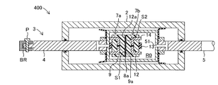
- One end of a rod member 3 that is a component of the door check device according to the present embodiment is connected to the bracket BR via a pin P.
- the rod member 3 whose one end is swingably connected to the vehicle body B is a hole formed in the front end portion DE of the vehicle door DR which is a portion facing the front edge portion FE of the vehicle body B when the vehicle door DR is fully closed. Via S, it extends into the vehicle door DR.
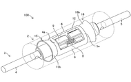
- FIG. 3 is a schematic perspective view showing the door check device 100 according to the first embodiment.
- the door check device 100 is provided between the vehicle body B and the vehicle door DR, and generates a holding force when the vehicle door DR is opened and closed.
- the door check device 100 includes a cylinder member 2 and a rod member 3.
- the cylinder member 2 is attached to the vehicle door DR.
- the cylinder member 2 is disposed in the internal space of the door panel that constitutes the vehicle door DR.
- the cylinder member 2 has a hollow cylindrical shape having one end surface 2a and the other end surface 2b, and a fluid such as oil is enclosed therein.
- a first through hole 21 is formed on one end surface 2a, and a second through hole 22 is formed on the other end surface 2b.
- the rod member 3 is swingably connected to the vehicle body B at one end thereof as described above, and penetrates the cylinder member 2 in the axial direction via the first through hole 21 and the second through hole 22. To do.
- the rod member 3 swings with respect to the vehicle body B according to the opening / closing operation of the vehicle door DR, and moves relative to the cylinder member 2 in the axial direction. Since the swing center position of the rod member 3 and the swing center position of the vehicle door DR are different, the rod member 3 moves in the axial direction while swinging with respect to the vehicle door DR when the vehicle door DR is opened and closed.
- the cylinder member 2 is preferably attached to the vehicle door DR so as to be swingable so that the cylinder member 2 can swing with the rod member 3 as the rod member 3 swings with respect to the vehicle door DR.
- FIG. 4 is an internal perspective view of the door check device 100.
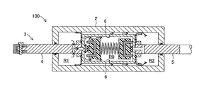
- FIG. 5 is a partial cross-sectional schematic view of the door check device 100 cut along the axial direction of the rod member 3.
- the rod member 3 includes a first rod portion 4, a second rod portion 5, and a connecting member 6, and the rod member 3 is configured by connecting them in series. Is done.
- the first rod portion 4 is connected to a bracket BR fixed to the front edge portion FE of the vehicle body B at one end of the first rod portion 4 via a pin P so as to be swingable. It is inserted into the member 2.
- One end of the second rod portion 5 is a free end. The second rod portion 5 is inserted into the cylinder member 2 via the second through hole 22.
- the first wall portion 4 a is formed at the other end of the first rod portion 4. Further, a second wall portion 5 a is formed at the other end of the second rod portion 5. And the 1st wall part 4a and the 2nd wall part 5a are connected by the connection member 6.
- 1st wall part 4a is arrange
- the second wall portion 5a is also disposed in the cylinder member 2 and has an outer surface facing the other end surface 2b side of the cylinder member 2 and an inner surface facing the one end surface 2a side.
- the first wall portion 4 a is disposed at a position near the one end surface 2 a in the cylinder member 2, and the second wall portion 5 a is disposed at a position near the other end surface 2 b in the cylinder member 2.
- Both wall portions 4a and 5a are arranged in the cylinder member 2 so that the inner surface of the first wall portion 4a faces the inner surface of the second wall portion 5a.
- the inner surface of the first wall portion 4 a forms the other end surface of the first rod portion 4
- the inner surface of the second wall portion 5 a forms the other end surface of the second rod portion 5.
- a first opening 41 is formed on the inner surface of the first wall portion 4a (the other end surface of the first rod portion 4).
- a second opening 51 is formed on the inner surface of the second wall portion 5a (the other end surface of the second rod portion 5).
- Both the 1st wall part 4a and the 2nd wall part 5a are comprised including the magnetic material.
- the first wall 4a and the second wall 5a are connected by the connecting member 6. Therefore, the 1st rod part 4, the 2nd rod part 5, and the connection member 6 operate
- the 1st wall part 4a, the 2nd wall part 5a, and the connection member 6 are shape
- these members may be configured as separate bodies.
- the 1st rod part 4 and the 1st wall part 4a may be shape
- the 2nd rod part 5 and the 2nd wall part 5a may be shape
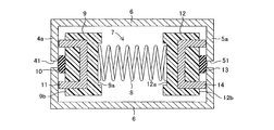
- FIG. 6 is a schematic cross-sectional view showing the first wall 4a, the second wall 5a, the connecting member 6, and the valve unit 7.
- the 1st opening 41 is formed in the center part of the 1st wall part 4a
- the 2nd opening 51 is formed in the center part of the 2nd wall part 5a.
- the connection member 6 connects the upper part and the lower part in the drawings of the first wall part 4a and the second wall part 5a.
- the first wall portion 4a, the second wall portion 5a, and the connection member 6 constitute a case-like member having an open side surface as shown in FIG. 4, and the valve unit 7 is disposed in the case-like member.
- fluid such as oil is sealed in the cylinder member 2, and the valve unit 7 is disposed in the cylinder member 2 in a state of being immersed in the fluid in the cylinder member 2.
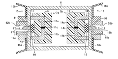
- the valve unit 7 includes a spring 8 (expandable member), a first valve case 9, a first valve body 10, a first magnetic force generating member 11, a second valve case 12, a second valve body 13, 2 magnetic force generation member 14.
- the spring 8 as an expansion / contraction member is a compression coil spring, and is disposed in the intermediate region R0 in the cylinder member 2 so as to be expandable / contractible in the axial direction of the cylinder member 2.
- the elastic force of the spring 8 used in this embodiment is very small, can be easily expanded and contracted, and the elastic force generated during expansion and contraction is very small.
- the first valve case 9 is attached to one end (left end in FIG. 6) of the spring 8 and the second valve case 12 is attached to the other end (right end in FIG. 6).
- the first valve case 9 has an inner surface 9 a that locks one end of the spring 8 and an outer surface 9 b on the opposite side.
- the outer side surface 9b faces the first wall portion 4a.
- the first valve body 10 is held on the outer side surface 9b.
- the second valve case 12 has an inner side surface 12 a that locks the other end of the spring 8 and an outer side surface 12 b on the opposite side.
- the outer side surface 12b faces the second wall portion 5a.
- the second valve body 13 is held on the outer side surface 12b.
- the first valve body 10 protrudes from the outer surface 9b of the first valve case 9, and the tip portion thereof has a conical shape and faces the first opening 41 formed in the first wall portion 4a. Accordingly, the first valve body 10 can be engaged with the periphery of the first opening 41 by receiving the elastic force of the spring 8 to seal the first opening 41.
- the 2nd valve body 13 protrudes from the outer surface 12b of the 2nd valve case 12, The front-end
- the first magnetic force generating member 11 is embedded in the first valve case 9.
- the first magnetic force generation member 11 is a U-shaped magnet having a pair of arms, and one arm is magnetized to the N pole and the other arm is magnetized to the S pole. And the front end surface of both arms protrudes from the outer side surface 9b of the 1st valve case 9, and faces the 1st wall part 4a.
- the 1st wall part 4a is comprised including the magnetic material. Therefore, a magnetic path is formed that returns from one arm of the first magnetic force generation member 11 to the other arm of the first magnetic force generation member 11 via the first wall portion 4a, and this magnetic path is used as the first magnetic force generation member.
- the first valve case 9 When the magnetic flux from 11 flows, a magnetic force is generated between the first wall portion 4 a and the first magnetic force generation member 11.
- the first valve case 9 is attracted to the first wall portion 4a by such magnetic force.
- the protruding amount of the first magnetic force generating member 11 from the outer surface 9 b of the first valve case 9 is equal to or slightly smaller than the protruding amount of the first valve body 10.
- a second magnetic force generating member 14 is embedded in the second valve case 12.
- the second magnetic force generation member 14 is also a U-shaped magnet provided with a pair of arms, one arm is magnetized to the N pole, and the other arm is magnetized to the S pole. And the front end surface of both arms protrudes from the outer surface 12b of the 2nd valve case 12, and faces the 2nd wall part 5a.
- the 2nd wall part 5a is comprised including the magnetic material. Therefore, a magnetic path is formed to return from one arm of the second magnetic force generation member 14 to the other arm of the second magnetic force generation member 14 via the second wall portion 5a, and this magnetic path is used as the second magnetic force generation member.
- the second valve case 12 When the magnetic flux from 14 flows, a magnetic force is generated between the second wall portion 5a and the second magnetic force generation member 14.
- the second valve case 12 is attracted to the second wall portion 5a by such magnetic force.
- the amount of protrusion of the second magnetic force generation member 14 from the outer surface 12 b of the second valve case 12 is equal to or slightly smaller than the amount of protrusion of the second valve body 13.
- a first cylindrical seal packing 15 made of rubber is attached to the first wall portion 4 a constituting the other end of the first rod portion 4.
- the first cylindrical seal packing 15 includes a circular first fixing portion 15a having a hole formed in the center, and a first lip portion 15b erected in an umbrella shape from the periphery of the first fixing portion 15a.
- the appearance is like a wide-mouthed cup with a diameter increasing toward the tip.
- fixed part 15a is attached to the outer surface of the 1st wall part 4a.
- the first lip portion 15b extends radially from the first fixing portion 15a so as to be inclined from the peripheral edge of the first fixing portion 15a fixed to the first wall portion 4a toward the one end face 2a side of the cylinder member 2.
- the diameter of the circle formed by the tip of the first lip portion 15b when the first cylindrical seal packing 15 is in the natural state is larger than the inner diameter of the cylinder member 2. Therefore, the space between the first wall 4a and the inner wall of the cylinder member 2 is covered by the first lip 15b, and the tip of the first lip 15b contacts the inner wall of the cylinder member 2 in the circumferential direction. The tip of the first lip portion 15b is urged against the inner wall of the cylinder member 2 with a predetermined elastic force. Therefore, the first cylindrical seal packing 15 causes the inside of the cylinder member 2 to be an intermediate region R0 that is a region between the first wall portion 4a and the second wall portion 5a (that is, a region where the valve unit 7 is disposed). In addition, the cylinder member 2 is partitioned into a first end region R1 which is a region where the first rod portion 4 is disposed.
- the fluid differential pressure ⁇ P1 acts on the first lip portion 15b so that the tip portion of the first lip portion 15b is lifted from the inner wall of the cylinder member 2. For this reason, a gap is formed between the tip of the first lip portion 15b and the inner wall of the cylinder member 2, and the fluid in the intermediate region R0 flows through the gap to the first end region R1.
- the fluid differential pressure ⁇ P1 is a positive pressure
- the fluid differential pressure ⁇ P1 acts on the first lip portion 15b so that the first lip portion 15b is pressed against the inner wall of the cylinder member 2. Therefore, the fluid in the first end region R1 is obstructed by the first lip portion 15b and does not flow into the intermediate region R0. That is, the first cylindrical seal packing 15 allows a flow of fluid from the intermediate region R0 toward the first end region R1, and is a one-way that blocks a flow of fluid from the first end region R1 to the intermediate region R0. Acts as a valve.
- a second cylindrical seal packing 16 made of rubber is attached to the second wall portion 5 a constituting the other end of the second rod portion 5.
- the second cylindrical seal packing 16 includes a circular second fixing portion 16a having a hole formed in the center, and a second lip portion 16b erected in an umbrella shape from the periphery of the second fixing portion 16a. The appearance is like a wide-mouthed cup with a diameter increasing toward the tip.
- fixed part 16a is attached to the outer surface of the 2nd wall part 5a.
- the second lip portion 16b extends radially from the second fixing portion 16a so as to be inclined from the peripheral edge of the second fixing portion 16a fixed to the second wall portion 5a toward the other end surface 2b side of the cylinder member 2.
- the diameter of the circle formed by the tip of the second lip portion 16b when the second cylindrical seal packing 16 is in a natural state is larger than the inner diameter of the cylinder member 2. Therefore, the space between the second wall portion 5a and the inner wall of the cylinder member 2 is covered by the second lip portion 16b, and the tip of the second lip portion 16b contacts the inner wall of the cylinder member 2 in the circumferential direction. Then, the tip of the second lip portion 16 b is urged against the inner wall of the cylinder member 2 with a predetermined elastic force. Therefore, the second cylindrical seal packing 16 divides the inside of the cylinder member 2 into an intermediate region R0 and a second end region R2 that is an arrangement region of the second rod portion 4 in the cylinder member 2. .
- the first cylindrical seal packing 15 and the second cylindrical seal packing 16 are opposed to each other with the first wall portion 4 a, the second wall portion 5 a, and the valve unit 7 interposed therebetween in the cylinder member 2. Is arranged. Then, the first cylindrical seal packing 15 and the second cylindrical seal packing 16 divide the inside of the cylinder member 2 into three regions: a first end region R1, an intermediate region R0, and a second end region R2. Is done.
- the fluid differential pressure ⁇ P2 acts on the second lip portion 16b so that the tip portion of the second lip portion 16b is lifted from the inner wall of the cylinder member 2. For this reason, a gap is formed between the tip of the second lip portion 16b and the inner wall of the cylinder member 2, and the fluid in the intermediate region R0 flows through the gap to the second end region R2.
- the fluid differential pressure ⁇ P2 acts on the second lip portion 16b so that the second lip portion 16b is pressed against the inner wall of the cylinder member 2. Therefore, the fluid in the second end region R2 is obstructed by the second lip portion 16b and does not flow into the intermediate region R0.
- the second cylindrical seal packing 16 allows a flow of fluid from the intermediate region R0 toward the second end region R2 and blocks a flow of fluid from the second end region R2 toward the intermediate region R0. Acts as a valve.
- a first communication path 42 is formed inside the other end side of the first rod portion 4.
- the first communication passage 42 has a radial passage 42a and an axial passage 42b, and its cross section has a T-shape.
- the radial passage 42 a is formed along the radial direction of the first rod portion 4, and both ends thereof are side circumferential surfaces of the first rod portion 4 and are located in the first end region R 1 in the cylinder member 2.
- the axial passage 42b is formed along the axial direction of the first rod portion 4, and one end thereof communicates with the radial passage 42a.
- the other end of the axial passage 42b communicates with the first opening 41 of the first wall 4a.
- the first opening 41 opens in the intermediate region R0.
- the first opening 41 is an opening of the first communication path 42 to the intermediate region R0. Accordingly, when the first opening 41 is not closed by the first valve body 10, the intermediate region R0 and the first end region R1 are communicated by the first communication passage 42. On the other hand, when the first opening 41 is closed by the first valve body 10, the flow of the fluid in the first communication passage 42 is blocked, and the intermediate region R0 and the first end portion passing through the first communication passage 42 are blocked. Communication with the region R1 is blocked.
- a second communication path 52 is formed inside the other end of the second rod portion 5.
- the second communication passage 52 has a radial passage 52a and an axial passage 52b, and its cross section has a T shape.
- the radial passage 52 a is formed along the radial direction of the second rod portion 5, and both ends thereof are side circumferential surfaces of the second rod portion 5 and are portions located in the second end region R ⁇ b> 2 in the cylinder member 2.
- the axial passage 52b is formed along the axial direction of the second rod portion 5, and one end thereof communicates with the radial passage 52a.
- the other end of the axial passage 52b communicates with the second opening 51 of the second wall portion 5a.
- the second opening 51 opens in the intermediate region R0.
- the second opening 51 is an opening of the second communication path 52 to the intermediate region R0. Accordingly, when the second opening 51 is not closed by the second valve body 13, the intermediate region R0 and the second end region R2 are communicated by the second communication passage 52. On the other hand, when the second opening 51 is closed by the second valve body 13, the flow of the fluid in the second communication passage 52 is blocked, and the intermediate region R0 and the second end portion passing through the second communication passage 52 are blocked. Communication with the region R2 is blocked.
- seal member is provided on the inner wall portion of the first through hole 21 and the inner wall portion of the second through hole 22 of the cylinder member 2. These seal members prevent the fluid in the cylinder member 2 from leaking to the outside through the first through hole 21 and the second through hole 22 when the rod member 3 moves in the axial direction with respect to the cylinder member 2. .
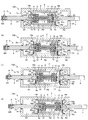
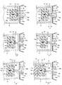
- FIG. 7 is a schematic cross-sectional view of the door check device 100 showing changes in the operation of the door check device 100 accompanying the opening operation of the vehicle door DR.
- FIG. 7A is a diagram illustrating an operating state of the door check device 100 when the vehicle door DR is fully closed
- FIG. 7B is a diagram illustrating that the vehicle door DR in the fully closed position starts an opening operation. It is a figure showing the operation state of the door check apparatus 100 immediately after
- FIG.7 (c) is a figure showing the operation state of the door check apparatus 100 when open operation is in progress
- FIG.7 (d) is an open operation. It is a figure showing the operating state of the door check apparatus 100 when it stops.
- the connecting member 6 is in the cylinder member 2. In FIG. 7, it is located on the right side (near the other end face 2b). Accordingly, the volume of the first end region R1, which is the region where the first rod portion 4 is provided on one end (left end) side of the connection member 6, is large, and is provided on the other end (right end) side of the connection member 6. The volume of the second end region R2, which is the region where the second rod portion 5 is provided, is small.
- the 1st valve body 10 is engaging with the periphery of the 1st opening 41 of the 1st wall part 4a. For this reason, the 1st opening 41 is closed by the 1st valve body 10, and the distribution
- the 2nd valve body 13 is engaging with the periphery of the 2nd opening 51 of the 2nd wall part 5a. For this reason, the 2nd opening 51 is also closed by the 2nd valve body 13, and the distribution
- the tips of both arms of the first magnetic force generating member 11 held by the first valve case 9 are closest to (or in contact with) the first wall 4a. Therefore, a strong magnetic force acts on the first valve case 9 so that the first valve case 9 is attracted to the first wall portion 4a.
- the first valve body 10 closes the first opening 41 and is biased with a strong force.
- Such a biasing force works as a holding force.
- the magnetic force acting on the first valve body 10 when the first valve body 10 closes the first opening 41 is greater than the elastic force of the spring 8 acting on the first valve body 10 at the same time. Much bigger.
- the tips of both arms of the second magnetic force generation member 14 held by the second valve case 12 are closest to (or in contact with) the second wall portion 5a. For this reason, a strong magnetic force acts on the second valve case 12 so that the second valve case 12 is attracted to the second wall portion 5a.
- the second valve body 13 closes the second opening 51 and is biased with a strong force.
- Such a biasing force works as a holding force.
- the magnetic force acting on the second valve body 13 when the second valve body 13 closes the second opening 51 is greater than the elastic force of the spring 8 acting on the second valve body 13 at the same time. Much bigger.
- FIG. 7A shows the operating state of the door check device 100 in such a case, that is, the operating state of the door check device 100 immediately after the vehicle door DR in the fully closed position starts the opening operation.
- the fluid pressure PR1 in the first end region R1 increases.
- the volume of the second end region R2 increases due to the change in the operating state of the door check device 100 from FIG. 7A to FIG. 7B, so that the fluid pressure PR2 in the second end region R2 increases. Will decline.
- the fluid pressure PR0 in the intermediate region R0 does not change. Therefore, when the operating state of the door check device 100 is the state shown in FIG. 7B, the magnitude relationship between the pressures in each region is PR1> PR0> PR2.
- the first end region R1 communicates with the first opening 41 that opens to the intermediate region R0 via the first communication path 42. Accordingly, the fluid pressure difference ⁇ P1 acts on the first valve body 10 that closes the first opening 41. At this time, the fluid differential pressure ⁇ P1 acts as a static fluid pressure in the direction in which the first valve body 10 moves away from the first opening 41 with respect to the first valve body 10. However, as described above, the first valve body 10 receives the magnetic force generated between the first magnetic force generating member 11 and the first wall portion 4a and the elastic force of the spring 8, that is, the holding force, and approaches the first opening 41. It is biased in the direction in which the first opening 41 is closed.
- the fluid differential pressure ⁇ P1 exceeds the urging force (holding force) acting on the first valve body 10, the sealing of the first opening 41 by the first valve body 10 is maintained.
- the magnitude of the fluid differential pressure ⁇ P1 changes according to the opening operation of the vehicle door DR, and represents the opening / closing operation force at the start of the opening operation.
- the fluid differential pressure ⁇ P2 acts on the second valve body 13 so as to close the second opening 51.
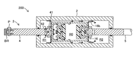
- FIG. 9 is a schematic cross-sectional view of the door check device 100 showing the flow of fluid in the cylinder member 2 when the first opening 41 is opened.
- the fluid in the first end region R1 flows into the intermediate region R0 and the fluid in the intermediate region R0 as shown by the arrow in FIG. 9 in accordance with the opening operation of the vehicle door DR. Flows to the second end region R2. As the fluid flows in this way, the pressure in each region in the cylinder member 2 is made uniform. By equalizing the pressure, the fluid differential pressure ⁇ P1 and the fluid differential pressure ⁇ P2 are reduced.
- the first valve body 10 is located between the first magnetic force generating member 11 and the first wall portion 4a. Is biased in the direction approaching the first opening 41 (to the left in FIG. 7) so as to seal the first opening 41.
- the distance between the 1st magnetic force generation member 11 and the 1st wall part 4a also becomes long.
- the magnetic force is inversely proportional to the square of the distance, when the distance between the first magnetic force generation member 11 and the first wall portion 4a is long, the first magnetic force generation member 11 and the first wall portion 4a are between. The resulting magnetic force is very small.
- the elastic coefficient of the spring 8 is very small, the elastic force generated by the spring 8 is also very small. That is, when the first valve body 10 is separated from the first opening 41 (when the first opening 41 is opened), the urging force (holding force) to the first opening 41 acting on the first valve body 10 is Very small. For this reason, even if the first valve body 10 moves toward the first opening 41 by the urging force, the fluid flowing from the first opening 41 to the intermediate region R0 with the opening operation of the vehicle door DR is the first valve body. The first valve body 10 is pushed back by a force that collides with 10 (hereinafter, this force may be referred to as a fluid resistance force). As a result, the release of the sealing of the first opening 41 by the first valve body 10 is maintained during the opening operation of the vehicle door DR.
- the fluid resistance force represents an opening / closing operation force when the vehicle door DR is being opened / closed. That is, when the operation state of the door check device 100 is the state shown in FIG. 7C, the vehicle door DR can be opened with a small opening / closing operation force. Thus, once the sealing of the first opening 41 by the first valve body 10 is released, the vehicle door DR can be opened with a small opening / closing operation force.
- the first valve body 10 approaches the first opening 41 by the magnetic force generated between the first magnetic force generation member 11 and the first wall portion 4 a and the elastic force by the spring 8.
- a guide member for guiding the movement of the first valve case 9 is preferably provided so that the first valve body 10 approaches the first opening 41 linearly.
- FIG. 7D shows the operating state of the door check device 100 in this state, that is, when the opening operation of the vehicle door DR is stopped.
- the first magnetic force generating member 11 is operated with respect to the opening operation of the vehicle door DR, as in the case shown in FIG. A large holding force is generated based on the magnetic force generated between the first wall portion 4a and the elastic force generated by the spring 8. Further, a large holding force based on the magnetic force generated between the second magnetic force generation member 14 and the second wall portion 5a and the elastic force of the spring 8 is generated with respect to the closing operation of the vehicle door DR. Therefore, when the vehicle door DR is stopped at an arbitrary opening position, the opening / closing operation of the vehicle door DR is prevented by a large holding force.
- FIG. 8 is a schematic cross-sectional view of the door check device 100 showing changes in the operation of the door check device 100 accompanying the closing operation of the vehicle door DR.
- FIG. 8A is a diagram illustrating the operating state of the door check device 100 when the vehicle door DR is fully opened
- FIG. 8B is a state immediately after the vehicle door DR in the fully open position starts the closing operation. It is a figure showing the operation state of the door check apparatus 100
- FIG.8 (c) is a figure showing the operation state of the door check apparatus 100 when it is during closing operation
- FIG.8 (d) stopped the closing operation It is a figure showing the operating state of the door check apparatus 100 at the time.
- the connecting member 6 is a view in the cylinder member 2. 8 is located on the left side (on the one end face 2a side). Therefore, the volume of the first end region R1, which is the region where the first rod portion 4 is provided on one end (left end) side of the connection member 6, is small, and is provided on the other end (right end) side of the connection member 6. The volume of the second end region R2, which is the region where the second rod portion 5 is disposed, is large.
- first opening 41 is closed by the first valve body 10
- the flow of the fluid in the first communication passage 42 is blocked
- the second opening 51 is closed by the second valve body 13
- the flow of fluid in the second communication path 52 is blocked.
- the tips of both arms of the first magnetic force generating member 11 held by the first valve case 9 are closest to (or in contact with) the first wall 4a. Therefore, a strong magnetic force acts on the first valve case 9 so that the first valve case 9 is attracted to the first wall portion 4a.
- the first valve body 10 closes the first opening 41 and is biased with a strong force.
- Such a biasing force works as a holding force.
- the tips of both arms of the second magnetic force generation member 14 held by the second valve case 12 are closest to (or in contact with) the second wall 5a.
- the volume of the second end region R2 decreases due to the change in the operating state of the door check device 100 from FIG. 8A to FIG. 8B, and the fluid pressure PR2 in the second end region R2 increases.
- the volume of the first end region R1 increases due to the change in the operating state of the door check device 100 from FIG. 8A to FIG. 8B, so that the fluid pressure PR1 in the first end region R1. Will decline.
- the volume of the intermediate region R0 does not change, the fluid pressure PR0 in the intermediate region R0 does not change. Therefore, when the operating state of the door check device 100 is the state shown in FIG. 8B, the magnitude relationship between the pressures in the respective regions is PR2> PR0> PR1.
- the second end region R2 communicates with the second opening 51 that opens to the intermediate region R0 via the second communication path 52. Accordingly, the fluid pressure difference ⁇ P2 acts on the second valve body 13 that closes the second opening 51. At this time, the fluid differential pressure ⁇ P2 acts as a static fluid pressure in a direction in which the second valve body 13 is separated from the second opening 51 with respect to the second valve body 13. However, as described above, the second valve body 13 receives the magnetic force generated between the second magnetic force generation member 14 and the second wall 5a and the elastic force of the spring 8, that is, the holding force, and approaches the second opening 51. It is biased in the direction in which the second opening 51 is closed.
- the fluid differential pressure ⁇ P2 exceeds the urging force (holding force) acting on the second valve body 13, sealing of the second opening 51 by the second valve body 13 is maintained.
- the magnitude of the fluid differential pressure ⁇ P2 changes according to the closing operation of the vehicle door DR, and represents the opening / closing operation force at the start of the closing operation.
- the fluid differential pressure ⁇ P1 acts on the first valve body 10 so as to close the first opening 41.
- FIG. 10 is a schematic cross-sectional view of the door check device 100 showing the flow of fluid in the cylinder member 2 when the second opening 51 is opened.
- the fluid in the second end region R2 flows into the intermediate region R0 and the fluid in the intermediate region R0 as shown by the arrow in FIG. 10 in accordance with the closing operation of the vehicle door DR. Flows to the first end region R1. As the fluid flows in this way, the pressure in each region in the cylinder member 2 is made uniform. By equalizing the pressure, the fluid differential pressure ⁇ P2 and the fluid differential pressure ⁇ P1 are reduced.
- the second valve body 13 is located between the second magnetic force generating member 14 and the second wall portion 5a. Is biased in the direction approaching the second opening 51 (to the right in FIG. 8) so as to seal the second opening 51.
- the distance between the 2nd magnetic force generation member 14 and the 2nd wall part 5a also becomes long.
- the magnetic force is inversely proportional to the square of the distance, when the distance between the second magnetic force generation member 14 and the second wall portion 5a is long, the second magnetic force generation member 14 and the second wall portion 5a are between. The resulting magnetic force is very small.
- the elastic coefficient of the spring 8 is very small, the elastic force generated by the spring 8 is also very small. That is, when the second valve body 13 is separated from the second opening 51 (when the second opening 51 is opened), the urging force (holding force) to the second opening 51 acting on the second valve body 13 is Very small. For this reason, even if the second valve body 13 moves toward the second opening 51 by the urging force, the fluid flowing from the second opening 51 to the intermediate region R0 with the closing operation of the vehicle door DR is the second valve body. The second valve body 13 is pushed back by the force (fluid resistance force) that collides with 13. As a result, the release of the sealing of the second opening 51 by the second valve body 13 is maintained during the closing operation of the vehicle door DR.
- the operation state of the door check device 100 is the state shown in FIG. 8C
- the urging force acting on the second valve body 13 is small as described above, and therefore, a small fluid resistance that exceeds a small urging force.
- the open state of the second opening 51 is maintained. That is, when the operation state of the door check device 100 is the state shown in FIG. 8C, the vehicle door DR can be closed with a small opening / closing operation force.
- the vehicle door DR can be closed with a small opening / closing operation force.
- the second valve body 13 approaches the second opening 51 by the magnetic force generated between the second magnetic force generation member 14 and the second wall portion 5 a and the elastic force by the spring 8.
- a guide member for guiding the movement of the second valve case 12 is preferably provided so that the second valve body 13 approaches the second opening 51 linearly.
- FIG. 8D shows the operating state of the door check device 100 in this state, that is, when the closing operation of the vehicle door DR is stopped.
- the second magnetic force generating member 14 is applied to the closing operation of the vehicle door DR, as in the case shown in FIG. And a large holding force based on the magnetic force generated between the second wall portion 5a and the elastic force of the spring 8 is generated. Further, a large holding force is generated based on the magnetic force generated between the first magnetic force generation member 11 and the first wall portion 4a and the elastic force of the spring 8 with respect to the opening operation of the vehicle door DR. Therefore, when the vehicle door DR is stopped at an arbitrary opening position, the opening / closing operation of the vehicle door DR is prevented by a large holding force.
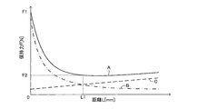
- FIG. 11 is a graph showing the relationship between the holding force F and the distance L, where the horizontal axis is the distance L and the vertical axis is the holding force F.
- the distance L is a distance between the first valve body 10 (or the second valve body 13) and the first opening 41 (or the second opening 51).
- the first valve body 10 (or the second valve body 13) engages with the peripheral edge of the first opening 41 (or the second opening 51) and the first opening 41 (or the second opening). 51) is closed.
- the distance L is greater than 0, the first valve body 10 (or the second valve body 13) is separated from the first opening 41 (or the second opening 51).
- a curve A indicated by a solid line indicates the relationship between the holding force F and the distance L.
- a curved line B shown by a one-dot chain line shows a relationship between the magnetic force Fm by the first magnetic force generating member 11 (or the second magnetic force generating member 14) and the distance L
- a curved line C shown by a broken line shows the elastic force Fe by the spring 8 and the distance.
- the relationship with L is shown.
- the holding force F is represented by the sum of the magnetic force Fm and the elastic force Fe.
- the magnetic force Fm is inversely proportional to the square of the distance
- the magnetic force Fm decreases rapidly as the distance L increases.
- the elastic force Fe is proportional to the distance, the amount of contraction of the spring 8 increases as the distance L increases, so that the elastic force Fe increases proportionally. Therefore, the magnitude relationship between the magnetic force Fm and the elastic force Fe is reversed at the boundary where the distance L is a predetermined length. Further, as can be seen from FIG. 11, when the distance L is L1, the holding force F (the sum of the magnetic force Fm and the elastic force Fe) is the smallest. The holding force F at this time is defined as the minimum holding force F2.
- the holding force F slightly increases as the distance L increases, but is almost constant. Therefore, in the door check device 100 according to the present embodiment, the holding force F generated when the distance L is small is very strong, and the holding force F rapidly decreases as the distance L increases.
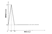
- FIG. 12 is a graph showing the relationship between the opening / closing operation force G required to open / close the vehicle door DR and the opening D of the vehicle door DR when the door check device 100 according to this embodiment is used.
- the horizontal axis represents the opening degree D
- the vertical axis represents the opening / closing operation force G.
- the opening degree D represents the magnitude of the rotation angle of the vehicle door DR from an arbitrary opening degree at which the opening / closing operation of the vehicle door DR is stopped.
- the operating state of the door check device 100 is the state shown in FIG. 7 (a) or FIG. 8 (a), or the state shown in FIG. 7 (d) or FIG. 8 (d). It is.
- the opening degree D is greater than 0 and equal to or less than D1
- the operating state of the door check device 100 is the state shown in FIG. 7B or FIG.
- the opening degree D is larger than D1
- the operating state of the door check device 100 is the state shown in FIG. 7 (c) or FIG. 8 (c).
- the opening / closing operation force G reaches the maximum holding force F1.
- the 1st valve body 10 or 2nd valve body 13
- the fluid differential pressure ⁇ P1 or ⁇ P2
- the required opening / closing operation force fluid resistance force
- the vehicle door DR is opened and closed by an opening / closing operation force slightly exceeding the minimum holding force F2. For this reason, the vehicle door DR can be opened and closed smoothly.
- the door check device 100 when the opening / closing operation of the vehicle door DR is stopped by using magnetic force as the holding force as shown in FIG.
- a small holding force can be generated. That is, it is possible to make a large difference between the opening / closing operation force when the opening / closing operation of the vehicle door DR is stopped and the opening / closing operation force during the opening / closing operation.
- the first valve body 10 and the second valve body 13 are both attached to the same spring 8, one spring is sufficient to generate an elastic force as a holding force. Therefore, a door check device having a simple configuration using one spring is provided.
- the spring 8 is immersed in the fluid in the cylinder member 2 in the cylinder member 2. For this reason, a special seal structure for preventing the fluid in the cylinder member 2 from flowing into the spring installation space is not required. Therefore, there is provided a door check device capable of generating a large holding force at an arbitrary opening position with a simple configuration without causing a complicated structure.
- magnetic force is used for the holding force.
- the first magnetic force generating member 11 (or the second magnetic force generating member 14) is closest to (or in contact with) the first wall portion 4a (or the second wall portion 5a).
- a large magnetic force can be applied to the first valve body 10 or the second valve body 13. For this reason, a large holding force can be generated.
- the first magnetic force generation member 11 (or the second magnetic force generation member 14) is generated by moving away from the first wall portion 4a (or the second wall portion 5a). Magnetic force suddenly weakens.
- the door check device 100 uses a magnetic force characteristic to generate a large holding force when the vehicle door opening / closing operation is stopped and a small holding force when the vehicle door opening / closing operation is performed. Since it is comprised so that the above-mentioned problem can also be solved.
- first cylindrical seal packing 15 and the second cylindrical seal packing 16 have both a function as a partition member that partitions the space in the cylinder member 2 and a function as a one-way valve. Therefore, compared with the case where the partition member and the one-way valve are configured separately, the door check device can be configured more simply, and the component cost can be reduced.
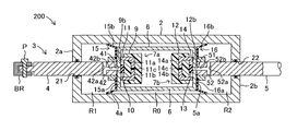
- FIG. 13 is a schematic cross-sectional view of a door check device 200 according to the second embodiment.
- FIG. 13 corresponds to FIG. 5 of the first embodiment.
- the door check device 200 according to the second embodiment is not provided with the spring 8 provided in the door check device 100 according to the first embodiment, and the first magnetic force generation member 11 and the second magnetic force generation member.
- 14 is the same as the door check device 100 according to the first embodiment except that the configuration of 14 is slightly changed. Accordingly, the same components are denoted by the same reference numerals, and detailed description thereof is omitted.
- the first magnetic force generation member 11 and the second magnetic force generation member 14 are configured by U-shaped magnets.
- the first magnetic force generation member 11 is U-shaped by a pair of arm members 11a and 11b made of a magnetic material and a chip-like permanent magnet 11c sandwiched between the pair of arm members 11a and 11b.
- the second magnetic force generating member 14 is formed in a U shape by a pair of arm members 14a and 14b made of a magnetic material and a chip-like permanent magnet 14c sandwiched between the pair of arm members 14a and 14b.
- the arm members 11a, 11b, 14a, and 14b have the same shape, and are formed in a curved bar shape like the shape of one arm of the U-shaped magnet.
- the permanent magnet 11c has an N pole surface and an S pole surface, the N pole surface is connected to one end surface of the arm member 11a, and the S pole surface is connected to one end surface of the arm member 11b.
- the shape of the first magnetic force generation member 11 is the same as the shape of the first magnetic force generation member made of the U-shaped magnet shown in the first embodiment.
- the permanent magnet 14c also has an N pole surface and an S pole surface, the N pole surface is connected to one end surface of the arm member 14a, and the S pole surface is connected to one end surface of the arm member 14b.
- the shape of the second magnetic force generation member 14 is the same shape as the shape of the second magnetic force generation member made of the U-shaped magnet shown in the first embodiment.
- the first magnetic force generation member 11 is embedded in the first valve case 9 so that the other end side (tip side) of the pair of arm members 11a and 11b is exposed from the outer surface 9b of the first valve case 9.
- the protruding amount of the pair of arm members 11a, 11b from the outer surface 9b of the first valve case 9 is equal to or slightly equal to the protruding amount of the first valve body 10 attached to the outer surface 9b of the first valve case 9. small.
- the second magnetic force generation member 14 is embedded in the second valve case 12 such that the other end side (tip side) of the pair of arm members 14 a and 14 b is exposed from the outer surface 12 b of the second valve case 12.
- the protruding amount of the pair of arm members 14a, 14b from the outer surface 12b of the second valve case 12 is equal to or slightly smaller than the protruding amount of the second valve body 13 attached to the outer surface 12b of the second valve case 12. .
- the door check device 200 does not include the spring 8 shown in the first embodiment. Therefore, the first valve case 9 and the second valve case 12 are not connected and can operate freely. That is, in the door check device 200 according to the present embodiment, the valve unit 7 described in the first embodiment is divided into a first valve unit 7a and a second valve unit 7b.
- the first valve unit 7a includes a first valve case 9, a first valve body 10, and a first magnetic force generation member 11, and the second valve unit 7b includes a second valve case 12, a second valve body 13, and a second valve body 7.
- a magnetic force generation member 14 is provided.
- the first valve body 10 when the opening / closing operation of the vehicle door DR is stopped, as shown in FIG. 13, the first valve body 10 is formed of the first opening 41 formed in the first wall portion 4a.
- the first opening 41 is closed by engaging the peripheral edge. For this reason, the flow of the fluid in the first communication passage 42 is blocked.
- the 2nd valve body 13 is closing the 2nd opening 51 by engaging with the periphery of the 2nd opening 51 formed in the 2nd wall part 5a. For this reason, the flow of fluid in the second communication passage 52 is blocked.
- the tip portions of the pair of arm members 11a and 11b of the first magnetic force generation member 11 held by the first valve case 9 are closest to (or contact) the first wall portion 4a. Therefore, a magnetic path is formed by the arm member 11a, the first wall portion 4a, and the arm member 11b.
- a strong magnetic force is generated between the first magnetic force generating member 11 and the first wall portion 4a, and the first valve unit 7a becomes the first valve unit 7a. It is drawn to 1 wall part 4a.
- this magnetic force acts on the first valve body 10 closes the first opening 41 and is biased with a strong force.
- Such an urging force acts as a holding force for the opening operation of the vehicle door DR.
- the tip portions of the pair of arm members 14a and 14b of the second magnetic force generation member 14 held by the second valve case 12 are closest to (or in contact with) the second wall portion 5a. Therefore, a magnetic path is formed by the arm member 14a, the second wall portion 5a, and the arm member 14b.
- a strong magnetic force is generated between the second magnetic force generation member 14 and the second wall portion 5a, and the second valve unit 7b is The two walls 5a are attracted.
- this magnetic force acts on the second valve body 13, the second valve body 13 closes the second opening 51 and is urged with a strong force.
- Such urging force acts as a holding force for the closing operation of the vehicle door DR.
- the rod member 3 moves in the axial direction relative to the cylinder member 2 with the opening operation of the vehicle door DR. In this case, the rod member 3 moves to the left in FIG. Then, the volume of the first end region R1 in the cylinder member 2 decreases and the fluid pressure PR1 in the first end region R1 increases. On the other hand, the volume of the second end region R2 in the cylinder member 2 increases and the fluid pressure PR2 in the second end region R2 decreases. Note that the fluid pressure PR0 in the intermediate region R0 does not change.
- the fluid differential pressure ⁇ P1 acts as a static fluid pressure in the direction in which the first valve body 10 moves away from the first opening 41 with respect to the first valve body 10.
- This fluid differential pressure ⁇ P1 represents the opening / closing operation force at the start of the opening operation of the vehicle door DR.
- the first valve body 10 receives the magnetic force (holding force) generated between the first magnetic force generation member 11 and the first wall portion 4a and approaches the first opening 41 (the first opening 41 is changed). Closed direction). Therefore, when the fluid differential pressure ⁇ P1 (open / close operation force) exceeds the urging force (holding force) acting on the first valve body 10 sealing the first opening 41, the first valve body 10 The first opening 41 opens away from the first opening 41.
- FIG. 14 is a schematic cross-sectional view of the door check device 200 showing a state in which the first opening 41 is opened.
- circulation of the fluid in the 1st communicating path 42 is cancelled
- the fluid differential pressure ⁇ P2 is a negative pressure, and when this negative pressure acts on the second lip portion 16b of the second cylindrical seal packing 16, the second lip portion 16b is lifted from the inner wall of the cylinder member 2, and A gap is formed between the two lip portions 16 b and the inner wall of the cylinder member 2. Through this gap, the fluid in the intermediate region R0 flows to the second end region R2.
- the fluid in the first end region R1 flows into the intermediate region R0 and the fluid in the intermediate region R0 as shown by the arrow in FIG. Flows to the second end region R2.
- the pressure in each region in the cylinder member 2 is made uniform.
- the fluid differential pressure ⁇ P1 and the fluid differential pressure ⁇ P2 are reduced.
- the distance between the 1st magnetic force generation member 11 and the 1st wall part 4a also gets longer. Since the magnetic force is inversely proportional to the square of the distance, when the distance between the first magnetic force generating member 11 and the first wall portion 4a is long, the magnetic force generated between the first magnetic force generating member 11 and the first wall portion 4a. Is very small.
- the urging force (magnetic force) acting on the first valve body 10 is small as described above, so that the fluid resistance is small enough to exceed the small urging force.
- the open state of the first opening 41 is maintained. That is, the vehicle door DR can be opened with a small opening / closing operation force.
- the vehicle door DR can be opened with a small opening / closing operation force.
- the opening operation of the vehicle door DR is stopped when the vehicle door DR is opened to an arbitrary opening position, the movement of the fluid in the cylinder member 2 is stopped. For this reason, the flow of fluid from the first opening 41 to the intermediate region R0 is stopped, and the fluid resistance force acting on the first valve body 10 disappears. Therefore, the first valve body 10 approaches the first opening 41 by the magnetic force generated between the first magnetic force generation member 11 and the first wall portion 4a.
- a guide member for guiding the movement of the first valve case 9 is preferably provided so that the first valve body 10 approaches the first opening 41 linearly.
- the rod member 3 moves in the axial direction relative to the cylinder member 2 in accordance with the closing operation of the vehicle door DR. In this case, the rod member 3 moves to the right of FIG. Then, the volume of the first end region R1 in the cylinder member 2 increases and the fluid pressure PR1 in the first end region R1 decreases. On the other hand, the volume of the second end region R2 in the cylinder member 2 decreases and the fluid pressure PR2 in the second end region R2 increases. Note that the fluid pressure PR0 in the intermediate region R0 does not change.
- the fluid differential pressure ⁇ P2 acts as a static fluid pressure in the direction in which the second valve body 13 moves away from the second opening 51 with respect to the second valve body 13.
- This fluid differential pressure ⁇ P2 represents the opening / closing operation force at the start of the closing operation of the vehicle door DR.
- the second valve body 13 receives a magnetic force (holding force) generated between the second magnetic force generation member 14 and the second wall portion 5a and approaches the second opening 51 (the second opening 51 is opened). Closed direction). Therefore, when the fluid differential pressure ⁇ P2 (open / close operation force) exceeds the urging force (holding force) acting on the second valve body 13 sealing the second opening 51, the second valve body 13 The second opening 51 opens away from the second opening 51.
- FIG. 15 is a schematic cross-sectional view of the door check device 200 showing a state in which the second opening 51 is opened.
- circulation of the fluid in the 2nd communicating path 52 is cancelled
- the fluid differential pressure ⁇ P1 is a negative pressure, and when the negative pressure acts on the first lip portion 15b of the first cylindrical seal packing 15, the first lip portion 15b is lifted from the inner wall of the cylinder member 2, and A gap is formed between the 1 lip portion 15 b and the inner wall of the cylinder member 2. Through this gap, the fluid in the intermediate region R0 flows to the first end region R1.
- the fluid in the second end region R2 flows into the intermediate region R0 and flows in the intermediate region R0 as shown by the arrow in FIG. 15 in accordance with the closing operation of the vehicle door DR.
- the fluid flows to the first end region R1.
- the pressure in each region in the cylinder member 2 is made uniform.
- the fluid differential pressure ⁇ P1 and the fluid differential pressure ⁇ P2 are reduced.
- the second magnetic force generating member 14 is separated from the second wall portion 5a, and the distance between the second magnetic force generating member 14 and the second wall portion 5a. Also gets longer. Since the magnetic force is inversely proportional to the square of the distance, when the distance between the second magnetic force generating member 14 and the second wall portion 5a is long, the magnetic force generated between the second magnetic force generating member 14 and the second wall portion 5a. Is very small. For this reason, even if the second valve body 13 moves toward the second opening 51 due to the urging force (magnetic force), the fluid of the fluid that flows from the second opening 51 to the intermediate region R0 with the closing operation of the vehicle door DR. The second valve body 13 is pushed back by the resistance force. As a result, the release of the sealing of the second opening 51 by the second valve body 13 is maintained during the opening operation of the vehicle door DR.
- the urging force (magnetic force) acting on the second valve body 13 is small as described above, and thus a small fluid resistance that exceeds the small urging force.
- the open state of the second opening 51 is maintained. That is, the vehicle door DR can be closed with a small opening / closing operation force.
- the sealing of the second opening 51 by the second valve body 13 is released, the vehicle door DR can be closed with a small opening / closing operation force.
- the closing operation of the vehicle door DR is stopped when the vehicle door DR is closed to an arbitrary opening position, the movement of the fluid in the cylinder member 2 is stopped. For this reason, the flow of fluid from the second opening 51 to the intermediate region R0 is stopped, and the fluid resistance force acting on the second valve body 13 disappears. Therefore, the second valve body 13 approaches the second opening 51 by the magnetic force generated between the second magnetic force generation member 14 and the second wall portion 5a.
- a guide member for guiding the movement of the second valve case 12 is preferably provided so that the second valve body 13 approaches the second opening 51 linearly. And the 2nd valve body 13 hold
- the operating state of the door check device 200 returns to the state shown in FIG.
- the second magnetic force generation member 14 is closest to (or is in contact with) the second wall portion 5a, a strong magnetic force is generated again.
- a strong biasing force acts on the second valve body 13. That is, a large holding force acts on the vehicle door DR.
- the holding force is generated only by the magnetic force.
- the valve bodies (the first valve body 10 and the second valve body 13) are separated from the openings (the first opening 41 and the second opening 51).
- the magnetic force generated between the two members is increased. Is quickly weakened. Therefore, thereafter, the vehicle door DR can be opened and closed smoothly, that is, with a small opening / closing operation force.
- the fluid resistance force acting on the valve body (10, 13) is small because the flow velocity of the fluid flowing from the opening (41, 51) into the intermediate region R0 is low.
- the magnetic force (or the magnetic force and the elastic force of the spring 8) generated between the magnetic force generating members (11, 14) and the wall portions (4a, 5a) becomes larger than the fluid resistance force, and the vehicle door DR is opened and closed.
- the openings (41, 51) may be closed by the valve bodies (10, 13).
- the door check device does not close the openings (41, 51) during the opening / closing operation of the vehicle door DR even when the vehicle door DR is opened and closed slowly. Therefore, the vehicle door DR can be opened and closed smoothly.
- FIG. 16 is a schematic cross-sectional view of a door check device 300 according to the third embodiment
- FIG. 17 is a diagram showing a configuration of the door check device 300 shown in FIG. is there.
- FIG. 16 corresponds to FIG. 5 of the first embodiment and FIG. 13 of the second embodiment.
- the door check device 300 shown in FIG. 16 has basically the same configuration as the door check device 200 according to the second embodiment, except that it includes a first protrusion member 17 and a second protrusion member 18 described later. Accordingly, the same components are denoted by the same reference numerals, and detailed descriptions thereof are omitted.
- the first valve body 10 when the opening / closing operation of the vehicle door DR is stopped, the first valve body 10 is formed on the first wall portion 4a as shown in FIGS. 16 and 17. The peripheral edge of the opening 41 is engaged. For this reason, the first valve body 10 closes the first opening 41 and blocks the fluid flow in the first communication passage 42. Moreover, the 2nd valve body 13 is engaging with the periphery of the 2nd opening 51 formed in the 2nd wall part 5a. For this reason, the second valve body 13 closes the second opening 51 and blocks the flow of fluid in the second communication passage 52.
- the tip portions of the pair of arm members 11a and 11b of the first magnetic force generation member 11 held by the first valve case 9 are closest to (or in contact with) the first wall portion 4a. Therefore, a magnetic path is formed by the arm member 11a, the first wall portion 4a, and the arm member 11b.
- a strong magnetic force is generated between the first magnetic force generating member 11 and the first wall portion 4a, and the first valve unit 7a is It is attracted to the first wall 4a.
- this magnetic force acts on the first valve body 10 closes the first opening 41 and is biased with a strong force.
- Such an urging force acts as a holding force for the opening operation of the vehicle door DR.
- the tip portions of the pair of arm members 14a and 14b of the second magnetic force generation member 14 held by the second valve case 12 are closest to (or in contact with) the second wall portion 5a. Therefore, a magnetic path is formed by the arm member 14a, the second wall portion 5a, and the arm member 14b.
- a strong magnetic force is generated between the second magnetic force generation member 14 and the second wall portion 5a, and the second valve unit 7b It is attracted to the second wall 5a.
- this magnetic force acts on the second valve body 13, the second valve body 13 is urged against the second opening 51 with a strong force.
- Such urging force acts as a holding force for the closing operation of the vehicle door DR.
- the door check device 300 includes a first projecting member 17 and a second projecting member 18.
- the first protruding member 17 is attached on the surface of the first valve body 10 that faces the first opening 41.
- the first projecting member 17 enters the axial passage 42 b of the first communication passage 42 via the first opening 41 when the first valve body 10 is engaged with the peripheral edge of the first opening 41. In this way, the first valve body 10 is extended.
- the second projecting member 18 is attached on the surface of the second valve body 13 that faces the second opening 51.
- the second projecting member 18 enters the axial passage 52 b of the second communication passage 52 via the second opening 51 when the second valve body 13 is engaged with the peripheral edge of the second opening 51. In this manner, the second valve body 13 is extended.
- the 1st projection member 17 has the 1st cylindrical part 17a and the 1st cone part 17b.
- the first cylindrical portion 17 a extends from the surface of the first valve body 10.
- the first columnar portion 17 a is disposed in the axial direction of the axial passage 42 b within the axial passage 42 b of the first communication passage 42 ( It extends along the axial direction of the first rod portion 4.
- the central axis of the first cylindrical portion 17a substantially coincides with the central axis of the axial passage 42b.
- the first cylindrical portion 17a has a constant cross-sectional shape (circular shape) along its axial direction.
- the cross-sectional area perpendicular to the axial direction of the first cylindrical portion 17a is constant along the axial direction.
- the 1st cone part 17b is formed from the front-end
- the tip surface of the first cylindrical portion 17a also serves as the bottom surface of the first conical portion 17b.
- the first conical portion 17b is configured such that the cross-sectional area perpendicular to the height direction (that is, the extending direction of the first cylindrical portion 17a) decreases from the bottom surface toward the apex, that is, toward the tip.
- the second projecting member 18 has a second cylindrical portion 18a and a second conical portion 18b.
- the second cylindrical portion 18 a extends from the surface of the second valve body 13.
- the second cylindrical portion 18 a moves in the axial direction of the axial passage 52 b in the axial passage 52 b of the second communication passage 52 ( It extends along the axial direction of the second rod portion 5.
- the central axis of the second cylindrical portion 18a substantially coincides with the central axis of the axial passage 52b.
- the second cylindrical portion 18a has a constant cross-sectional shape (circular shape) along its axial direction.
- the cross-sectional area perpendicular to the axial direction of the second cylindrical portion 18a is constant along the axial direction.
- the 2nd cone part 18b is formed from the front-end
- the tip surface of the second cylindrical portion 18a also serves as the bottom surface of the second conical portion 18b.
- the second conical portion 18b is configured such that the cross-sectional area perpendicular to the height direction (that is, the extending direction of the second cylindrical portion 18a) decreases from the bottom surface toward the apex, that is, toward the tip.
- FIG. 18 shows an operating state of the door check device 300 when the vehicle door DR is closing.
- the arrows in FIG. 18 indicate the flow of fluid in the cylinder member 2 when the vehicle door DR is closing.
- the door check device 300 when the vehicle door DR is opened, as in the case of using the door check devices 100 and 200 according to the first and second embodiments.
- the first valve body 10 is separated from the first opening 41, the first opening 41 is opened, and the fluid in the first communication passage 42 flows from the first opening 41 to the intermediate region R0.
- the second valve body 13 is separated from the second opening 51, the second opening 51 is opened, and the fluid in the second communication path 52 passes from the second opening 51 to the intermediate region R0. Flowing into.
- the fluid resistance force of the fluid flowing in the intermediate region R0 is constant.
- the fluid resistance force of the fluid flowing from the opening (41, 51) to the intermediate region R0 is It changes depending on the length of the distance L between the body (the first valve body 10 and the second valve body 13) and the opening (41, 51). Specifically, when the distance L is small, the fluid resistance is large, and when the distance L is large, the fluid resistance is small. This point will be described below by taking as an example a case where the vehicle door DR is closed using the door check device 300.
- FIG. 19 is a diagram illustrating a change in the distance L between the second valve body 13 and the second opening 51 when the vehicle door DR is closed using the door check device 300 according to the present embodiment.
- the second valve body 13 When the vehicle door DR starts the closing operation, the second valve body 13 gradually moves away in response to the fluid resistance force of the fluid flowing from the second opening 51 to the intermediate region R0. That is, the distance L increases gradually. At this time, the second valve body 13 is positioned in the order shown in FIG. 19 (a) ⁇ FIG. 19 (b) ⁇ FIG. 19 (c) ⁇ FIG. 19 (d) ⁇ FIG. 19 (e) ⁇ FIG. To change.
- the distance L between the second valve body 13 and the second opening 51 is represented as L1.
- the second cylindrical portion 18a of the second projecting member 18 is located in the second opening 51 (more precisely, the opening surface of the second opening 51 to the intermediate region R0). Accordingly, the fluid in the second communication passage 52 flows into the intermediate region R0 through the ring-shaped gap between the peripheral edge of the second opening 51 and the second cylindrical portion 18a.
- the distance L between the second valve body 13 and the second opening 51 is represented as L2.
- the boundary between the second cylindrical portion 18a and the second conical portion 18b is located in the second opening 51.
- the distance L between the second valve body 13 and the second opening 51 is represented as L3.
- the second conical portion 18b is located in the second opening 51. Accordingly, the fluid in the second communication path 52 flows to the intermediate region R0 through a ring-shaped gap between the peripheral edge of the second opening 51 and the conical surface of the second conical portion 18b.
- the distance L between the second valve body 13 and the second opening 51 is represented as L4.
- the vertex of the second conical portion 18b is located in the second opening 51.
- the distance L between the second valve body 13 and the second opening 51 is represented as L5.
- the distance L is L5
- the second projecting member 18 is completely removed from the second communication path 52. Therefore, the fluid in the second communication passage 52 flows through the circular space in the second opening 51 to the intermediate region R0. At this time, when the second valve case 12 contacts the first valve case 9, further movement of the second valve body 13 is restricted.
- each distance L1, L2, L3, L4, L5 is L1 ⁇ L2 ⁇ L3 ⁇ L4 ⁇ L5.
- the shapes of the first opening 41 and the second opening 51 are circles.
- the second cylindrical portion 18a of the second projecting member 18 is located in the second opening 51.
- the width of the ring-shaped gap that passes when the fluid in the second communication passage 52 flows to the intermediate region R0 is the narrowest.
- the cross-sectional area of the second cylindrical portion 18a is constant along the axial direction. Therefore, when the distance L is greater than 0 and less than or equal to L2, the width of the ring-shaped gap through which the fluid in the second communication path 52 passes is constant even when the distance L increases.
- the second conical portion 18b of the second projecting member 18 is located in the second opening 51. At this time, the width of the ring-shaped gap that passes when the fluid in the second communication passage 52 flows into the intermediate region R0 gradually increases as the distance L increases, and the gap when the distance L reaches L4. The width of is the maximum.
- the flow rate Q of the fluid passing through the ring-shaped gap is expressed by the following equation (1).
- ⁇ P is the pressure of the fluid flowing through the ring-shaped gap [MPa]
- d is the inner diameter [mm] of the ring-shaped gap
- D is the outer diameter of the ring-shaped gap [mm]
- ⁇ is the kinematic viscosity [mm 2 ⁇ s] of the fluid flowing through the ring-shaped gap
- l is the length of the ring-shaped gap [mm]
- ⁇ is the density [kg ⁇ m 3 ] of the fluid flowing through the ring-shaped gap.
- FIG. 20 shows the relationship among d, D, and ⁇ .
- formula (2) is obtained. From equation (2), it can be seen that when the flow rate Q is constant, the pressure of the fluid flowing through the ring-shaped gap is generally large when the gap is wide and small when the gap is narrow. Further, ⁇ P in the equation (2) is the pressure of the fluid flowing from the second opening 51 into the intermediate region R0, that is, the fluid resistance force in the present embodiment. From this, the fluid resistance is large when the flow rate Q is constant, that is, when the vehicle door DR is opened and closed at a constant speed, and is large when the width of the ring-shaped gap is narrow and small when it is wide. Recognize.
- the width of the ring-shaped gap is the narrowest. Therefore, the fluid resistance force of the fluid flowing through the second opening 51 to the intermediate region R0 is the largest. From this, when the second valve body 13 is immediately after the second opening 51 is separated and the distance L is small, the second valve body 13 exerts a strong fluid resistance force from the fluid flowing from the second opening 51 into the intermediate region R0. I understand that I will receive it. In other words, a decrease in the fluid resistance force when the distance L is small immediately after the second opening 51 is opened can be suppressed.
- the second valve body 13 when the second valve body 13 is moved away from the second opening 51 by a strong fluid resistance force, the second valve body 13 is secondly moved by the magnetic force generated between the second magnetic force generation member 14 and the second wall portion 5a.
- the approach to the opening 51 can be effectively prevented.
- the width of the ring-shaped gap gradually increases. Therefore, the fluid resistance force gradually decreases.
- the second projecting member 18 is completely removed from the second communication path 52, and the fluid pressure resistance is minimized.
- the second magnetic force generation member 14 is largely separated from the second wall portion 5a, the fluid pressure resistance is small, but the magnetic force generated between the second magnetic force generation member 14 and the second wall portion 5a is even smaller. . Accordingly, it is possible to effectively prevent the second valve body 13 from approaching the second opening 51 due to the magnetic force.
- the fluid resistance force at the initial opening and closing of the vehicle door DR is increased.
- the fluid resistance is reduced. That is, when the vehicle door DR is opened and closed at a constant low speed, the fluid resistance is large at the beginning of opening and closing, and the fluid resistance is reduced when the opening / closing operation proceeds to some extent.
- the magnetic force generated between them is relatively strong.
- the fluid resistance is smaller than the magnetic force, and the valve body (10, 13) may close the openings (41, 51).
- the fluid resistance force at the initial opening and closing is increased, so that it is away from the opening (41, 51).
- FIG. 21 shows the relationship between the distance L and the fluid resistance force Fp acting on the valve body (10, 13), and the distance L from the magnetic force generation member (11, 14) acting on the valve body (10, 13). It is a graph which shows the relationship with magnetic force Fm.
- the horizontal axis in FIG. 21 is the distance L, and the vertical axis is the force F.
- the graph A in FIG. 21 represents the relationship between the distance L and the fluid resistance force Fp
- the graph B represents the relationship between the distance L and the magnetic force Fm.
- the magnetic force Fm is inversely proportional to the distance L. Therefore, when the distance L is 0, the magnetic force Fm is the maximum magnetic force Fm0, and when the distance L increases, the magnetic force rapidly decreases.
- the distance L is 0 and the opening / closing operation force that applies a force Fp0 larger than the maximum magnetic force Fm0 to the valve body (10, 13) is applied to the vehicle door DR, the vehicle door DR starts opening / closing operation. At the same time, the valve bodies (10, 13) are separated from the openings (41, 51).
- the fluid resistance force is drastically increased by the fluid flowing from the opening (41, 51) to the intermediate region R0 by the fluid differential pressure ( ⁇ P1, ⁇ P2). descend.
- the gap through which the fluid flowing from the opening (41, 51) to the intermediate region R0 is narrowed due to the presence of the projecting members (the first projecting member 17, the second projecting member 18), the fluid resistance (fluid difference) Pressure) is suppressed, and the fluid resistance force Fp does not fall below the magnetic force Fm. And after the fluid resistance force Fp falls to Fp1, the magnitude
- the size of Fp1 is determined by the size of the gap between the opening (41, 51) and the cylindrical portion (17a, 18a) of the protruding member (17, 18).
- the fluid resistance is constant (Fp1).
- the fluid resistance force Fp decreases as the distance L increases.
- the conical portions (17b, 18b) of the projecting members (17, 18) are located in the openings (41, 51), and the gap of the fluid flowing into the intermediate region R0 gradually increases as the distance L increases.
- the fluid resistance force Fp also gradually decreases. For this reason, generation
- the fluid resistance force Fp becomes the minimum (Fp2).
- the fluid resistance force Fp is constant (Fp2) regardless of the increase in the distance L.
- the fluid resistance force Fp is always greater than the magnetic force Fm regardless of the size of the distance L. Accordingly, when the valve body (10, 13) approaches the opening (41, 51) by the magnetic force Fm during the opening / closing operation of the vehicle door DR, the opening (41, 51) is closed by the valve body (10, 13). Is prevented.
- the fluid resistance force Fp changes as shown by a broken line C in FIG. 21, and the magnetic force Fm is changed to the fluid resistance force Fp. There is a larger area.
- valve element (10, 13) closes the opening (41, 51) by the magnetic force Fm during the opening / closing operation of the vehicle door DR, and there is a risk that a large holding force acts on the vehicle door DR suddenly. is there. According to this embodiment, the occurrence of such a problem can be effectively prevented.
- the distance L2 is the length of the cylindrical portion (17a, 18a) of the protruding member (17, 18)
- the distance L4 is the total length of the protruding member (17, 18)
- the distance (L4-L2) is The height of the conical portions (17b, 18b) of the protruding members (17, 18). Therefore, when the characteristic of the fluid resistance force with respect to the distance L has a characteristic as shown in FIG. 21, in order to obtain such a characteristic, a cylindrical part having a predetermined diameter and a length L2, and a height ( A projecting member having a conical portion of L4-L2) is provided on the valve body (10, 13).
- the shape of the protruding members (17, 18) is designed so that the fluid resistance force Fp always exceeds the magnetic force Fm.
- the cylindrical portions (17a, 18a) so that the fluid resistance force Fp1 is larger than the magnetic force Fm when the cylindrical portions (17a, 18a) of the protruding members (17, 18) are positioned in the openings (41, 51).
- the length of the cylindrical portion (17a, 18a) so that the fluid resistance force Fp2 is larger than the magnetic force Fm when the projection (17, 18) is pulled out from the opening (41, 51).
- the height (length) of the conical portions (17b, 18b) are determined. As long as these requirements are satisfied, the shape of the protrusions (17, 18) can be freely selected.
- the conical portions (17b, 18b) of the projecting members (17, 18) first pass through the opening (41, 51) and communicate with each other. Enter (42, 52).
- the valve bodies (10, 13) are guided to the openings (41, 51) by the conical portions (17b, 18b) that have entered the communication passages (42, 52).
- the conical portions (17b, 18b) serve as positioning guides for the valve bodies (10, 13) with respect to the openings (41, 51)
- the openings (41, 51) can be closed by the valve bodies (10, 13), and a large holding force can be reliably applied to the vehicle door DR.
- the door check device 400 according to the present embodiment has the same configuration as that of the door check device 200 according to the second embodiment, except that a leaf spring 8a, which will be described later, is provided as an adsorption portion. Therefore, the same parts are denoted by the same reference numerals, and a specific description thereof is omitted.
- FIG. 22 is a schematic cross-sectional view of the door check device 400
- FIG. 23 is a schematic cross-sectional view showing the configuration in the cylinder member 2 in the configuration of the door check device 400 shown in FIG.
- the first magnetic force generating member 11 held by the first valve case 9 comes closest (or comes into contact) with the first wall portion 4a. Therefore, a magnetic path passing through the first wall 4a is formed. A strong magnetic force is generated between the first magnetic force generating member 11 and the first wall portion 4a by the magnetic flux from the first magnetic force generating member 11 flowing in the magnetic path formed in this way, and the first valve unit 7a. Is attracted to the first wall 4a. When this magnetic force acts on the first valve body 10, the first valve body 10 closes the first opening 41 and is biased with a strong force. Such an urging force acts as a holding force for the opening operation of the vehicle door DR.
- the second magnetic force generation member 14 held by the second valve case 12 comes closest to (or comes into contact with) the second wall portion 5a. For this reason, a magnetic path passing through the second wall portion 5a is formed. A strong magnetic force is generated between the second magnetic force generation member 14 and the second wall portion 5a by the magnetic flux from the second magnetic force generation member 14 flowing in the magnetic path formed in this way, and the second valve unit 7b. Is attracted to the second wall 5a. When this magnetic force acts on the second valve body 13, the second valve body 13 closes the second opening 51 and is urged with a strong force. Such urging force acts as a holding force for the closing operation of the vehicle door DR.
- the door check device 400 includes a leaf spring 8a.
- the leaf spring 8 a is disposed between the first valve case 9 and the second valve case 12 provided in the cylinder member 2. When the door check device 400 is in the operating state shown in FIG. 22, the leaf spring 8 a is not in contact with both the bubble cases 9 and 12.
- the leaf spring 8a is a flat plate member having a first plane S1 and a second plane S2 on the opposite side, and the center portion is bent in a natural state.
- the leaf spring 8a has a first valve case 9 such that its first plane S1 faces the inner side surface 9a of the first valve case 9, and its second plane S2 faces the inner side surface 12a of the second valve case 12. And the second valve case 12.
- the other structure is the same as the structure of the door check apparatus 100 which concerns on 2nd Embodiment, the description is abbreviate
- FIG. 24 shows a state immediately after the inner surface 12a of the second valve case 12 contacts the leaf spring 8a.
- the arrow in FIG. 24 shows the flow of the fluid in the cylinder member 2 during the closing operation of the vehicle door DR.
- the first flat surface S1 of the leaf spring 8a is stuck to the inner side surface 9a of the first valve case 9.
- the space between the inner side surface 9a and the first plane S1 of the leaf spring 8a becomes negative pressure, which resists the pulling force. Adsorption force is generated.
- the first valve unit 7a is attracted to the leaf spring 8a by this attracting force.
- the second flat surface S ⁇ b> 2 of the leaf spring 8 a is attached to the inner side surface 12 a of the second valve case 12.
- the second valve unit 7b is adsorbed to the leaf spring 8a. That is, the second valve unit 7b is connected to the first valve unit 7a via the leaf spring 8a by the attractive force of the leaf spring 8a. Further, the elastic force of the leaf spring 8a acts in a direction to separate the first valve unit 7a and the second valve unit 7b adsorbed by the leaf spring 8a. That is, the elastic force of the leaf spring 8a acts in a direction that weakens the adsorption force. Therefore, while the adsorption force by the leaf spring 8a is larger than the elastic force of the leaf spring 8a, the second valve unit 7b is in the state shown in FIG.
- the adsorption force of the leaf spring 8a is such that the clearance between the first plane S1 and the inner side surface 9a of the first valve case 9 and the second plane S2 of the leaf spring 8a and the inner side surface 12a of the second valve case 12 are as follows. As the fluid enters the gap little by little, it is weakened over time. When the suction force becomes smaller than the elastic force of the leaf spring 8a, the suction of the second valve unit 7b by the leaf spring 8a is released.
- the second valve unit 7b When the closing operation of the vehicle door DR is stopped when the adsorption of the second valve unit 7b is released, the second valve unit 7b is connected to the second magnetic force generating member 14 in addition to the elastic force from the leaf spring 8a. Due to the magnetic force generated between the second wall 5a and the second wall 5a, the second valve body 13 provided in the second valve case 12 is engaged with the peripheral edge of the second opening 51 and secondly. The opening 51 is closed. At this time, a large magnetic force acts on the second valve body 13, whereby a large holding force can be exerted on the vehicle door DR.
- the second valve case 12 is adsorbed to the first valve case 9 via the leaf spring 8a during the opening / closing operation of the vehicle door DR.
- the second valve body 13 can be prevented from moving in a direction approaching the second opening 51. Therefore, a large holding force is prevented from acting on the vehicle door DR during the opening / closing operation of the vehicle door DR, and as a result, the vehicle door DR can be opened and closed smoothly.
- valve units (7a, 7b) are arranged so that the opening / closing operation of the vehicle door DR does not stop before the suction of the valve units (first valve unit 7a, second valve unit 7b) is released. It is necessary to adjust the time for which is adsorbed. In this case, the adsorption time of the valve units (7a, 7b) can be adjusted by adjusting the elastic force of the leaf spring 8a.
- FIG. 26 is a schematic cross-sectional view of a door check device 500 according to the fifth embodiment.
- the door check device 500 according to the present embodiment includes a protruding member (17, 18) provided in the door check device 300 shown in the third embodiment and a leaf spring 8a provided in the door check device 400 shown in the fourth embodiment. Is the same as the configuration of the door check device 200 according to the second embodiment. Therefore, about the same structure as the door check apparatus which concerns on 2nd, 3rd, 4th embodiment, it shows with the same code
- the operation of the door check device 500 is the same as the operation of the door check device described in the second, third, and fourth embodiments, and the description thereof is omitted.
- the door check device 500 since the door check device 500 according to the present embodiment includes the protruding members (17, 18) similarly to the door check device 300 according to the third embodiment, the vehicle door DR is slowly opened and closed. Even in the case, the valve body (10, 13) is moved away from the opening (41, 51) at a stretch. When the valve element (10, 13) is moved away from the opening (41, 51) at a stretch, the distance between the magnetic force generating member (11, 14) and the wall (4a, 5a) becomes very large. The magnetic force acting on (10, 13) may be very weak. In such a case, the valve body (10, 13) may not move in the direction approaching the opening (41, 51) even after the opening / closing operation of the vehicle door DR is stopped.
- the second valve unit 7b when the second valve unit 7b is in the state shown in FIG. 27, an adsorption force is acting on the second valve unit 7b as described in the fourth embodiment. Therefore, the second valve unit 7b maintains the state shown in FIG. 27 until the adsorption force becomes weaker than the elastic force of the leaf spring 8a. That is, the second valve unit 7b does not move until a predetermined time. This effectively prevents the second valve unit 7b from moving in the direction approaching the second wall 5a and closing the second opening 51 during the closing operation of the vehicle door DR.
- the second valve unit 7b is connected to the first valve unit 7a via the leaf spring 8a by an adsorption force.
- the adsorption force acting on the second valve unit 7b is weakened with time.
- the second valve unit 7b is moved in a direction approaching the second wall portion 5a by the elastic force of the leaf spring 8a.
- the second valve unit 7b approaches the second wall 5a by the magnetic force generated between the second magnetic force generating member 14 and the second wall 5a.
- big holding force acts on the vehicle door DR.
- the valve bodies (10, 13) can be moved away from the openings (41, 51) at a time when the vehicle door DR is opened and closed. Further, during the opening / closing operation of the vehicle door DR, the valve unit (7a, ab) is prevented from moving for a predetermined time by the adsorption action of the leaf spring 8a, so that the valve unit moves during the opening / closing operation of the vehicle door DR.
- the opening (41, 51) is prevented from being sealed by the body (10, 13).
- valve body (10, 13) is brought close to the opening (41, 51) by the elastic force of the leaf spring 8a, thereby opening the valve body (10, 13) (41). , 51) can be sealed. For this reason, a large holding force can be generated when the opening / closing operation of the vehicle door DR is stopped.
- FIG. 28 is a schematic sectional view showing a door check device 600 according to the present embodiment.
- the first opening 41 is formed in the first wall portion 4a of the first valve body 10.
- the first opening 41 is closed because it is engaged with the peripheral edge. For this reason, the flow of the fluid in the first communication passage 42 is blocked.
- the 2nd valve body 13 is engaging with the peripheral edge of the 2nd opening 51 formed in the 2nd wall part 5a, the 2nd opening 51 is closed. For this reason, the flow of fluid in the second communication passage 52 is blocked.
- the door check device 600 includes a first auxiliary magnetic member 19a and a second auxiliary magnetic member 19b.
- the first auxiliary magnetic member 19 a is provided between the first valve body 10 and the first valve case 9, and the second auxiliary magnetic member 19 b is provided between the second valve body 13 and the second valve case 12.
- Both the first auxiliary magnetic member 19a and the second auxiliary magnetic member 19b are made of a material having high magnetic permeability (for example, iron).
- the first auxiliary magnetic member 19a is connected to the outer surface 9b of the first valve case 9 via a bonding member such as an adhesive, and further to the surface of the first auxiliary magnetic member 19a via a bonding member such as an adhesive.
- the valve body 10 is connected.
- the second auxiliary magnetic member 19b is connected to the outer surface 12b of the second valve case 12 via a bonding member such as an adhesive, and further, the surface of the second auxiliary magnetic member 19b is bonded via a bonding member such as an adhesive.
- the second valve body 13 is connected.
- the first auxiliary magnetic member 19 a is a tip portion of the arm member 11 a of the first magnetic force generation member 11 (that is, a portion of the arm member 11 a that protrudes from the outer surface 9 b of the first valve case 9).
- the distal end portion of the arm member 11b that is, the portion of the arm member 11b that protrudes from the outer surface 9b of the first valve case 9
- the respective distal end portions of the arm members 11a and 11b are separated by a predetermined distance. That is, a gap is provided between the arm members 11a and 11b and the first auxiliary magnetic member 19a.
- the second auxiliary magnetic member 19b includes a tip portion of the arm member 14a of the second magnetic force generation member 14 (that is, a portion of the arm member 14a that protrudes from the outer surface 12b of the second valve case 12) and the arm member 14b.
- the arm member 14b that is, the portion of the arm member 14b protruding from the outer surface 12b of the second valve case 12
- a predetermined distance from each of the tip portions of the arm members 14a and 14b. It is separated. That is, a gap is provided between the arm members 14a and 14b and the second auxiliary magnetic member 19b. Since other configurations are the same as the configuration of the door check device 200 shown in the second embodiment, the same portions are denoted by the same reference numerals, and detailed descriptions thereof are omitted.
- FIG. 29 is a diagram illustrating an operating state of the door check device 600 when the vehicle door DR is in the closing operation.
- the arrows in FIG. 29 represent the flow of fluid in the cylinder member 2 when the vehicle door DR is in the closing operation.
- the pair of arm members 11a and 11b of the first magnetic force generation member 11 held by the first valve case 9 is closest (or contacted) to the first wall portion 4a. To do. For this reason, a magnetic path (main magnetic path) passing through the arm member 11a, the first wall portion 4a, and the arm member 11b is formed. Further, the first auxiliary magnetic member 19 a provided between the first valve body 10 and the first valve case 9 is located between the pair of arm members 11 a and 11 b of the first magnetic force generation member 11. A magnetic path (sub magnetic path) passing through the arm member 11a, the first auxiliary magnetic member 19a, and the arm member 11b is also formed. That is, the first magnetic force generating member 11 forms a main magnetic path that passes through the first wall portion 4a and a sub magnetic path that passes through the first auxiliary magnetic member 19a.
- the pair of arm members 14a and 14b of the second magnetic force generation member 14 held by the second valve case 12 are closest to the second wall portion 5a ( (Or contact). For this reason, a magnetic path (main magnetic path) passing through the arm member 14a, the second wall portion 5a, and the arm member 14b is formed.
- the second auxiliary magnetic member 19b provided between the second valve body 13 and the second valve case 12 is located between the pair of arm members 14a, 14b of the second magnetic force generation member 14.
- a magnetic path (sub magnetic path) passing through the arm member 14a, the second auxiliary magnetic member 19b, and the arm member 14b is also formed. That is, the second magnetic force generation member 14 forms a main magnetic path that passes through the second wall portion 4a and a sub magnetic path that passes through the second auxiliary magnetic member 19b.
- FIG. 30 is a diagram illustrating a state in which the main magnetic path M1 and the sub magnetic path M2 are formed by the second magnetic force generation member 14 when the opening / closing operation of the vehicle door DR is stopped.
- the main magnetic path M1 passes through the second wall portion 5a
- the sub magnetic path M2 passes through the second auxiliary magnetic member 19b.
- the magnetic resistance of the main magnetic path M1. Is low.
- the magnetic resistance of the sub magnetic path M2 is high. That is, the permeance of the main magnetic path M1 is higher than the permeance of the sub magnetic path M2.
- FIG. 31 is a diagram showing a state in which the main magnetic path M1 and the sub magnetic path M2 are formed by the second magnetic force generation member 14 when the vehicle door DR is in the closing operation.
- the second valve body 13 is separated from the second opening 51, and the pair of arm members 14a, 14b of the second magnetic force generation member 14 is the second wall portion. Move away from 5a. That is, the arm members 14a and 14b are separated from the fifth wall portion 5a by a predetermined distance, and a relatively large gap is formed between the arm members 14a and 14b and the second wall portion 5a. Therefore, the magnetic resistance of the main magnetic path M1 is high and the permeance is low. Further, since the pair of arm members 14a, 14b of the second magnetic force generation member 14 is also separated from the second auxiliary magnetic member 19b by a predetermined distance, the magnetic resistance of the sub magnetic path M2 is high and the permeance is low.
- the secondary magnetic path M2 does not exist, the magnetic flux from the second magnetic force generation member 14 must pass through the main magnetic path M1, whereas in the present embodiment, the secondary magnetic path M2 exists.
- the magnetic flux from the second magnetic force generation member 14 passes through both the main magnetic path M1 and the sub magnetic path M2. That is, the presence of the secondary magnetic path M2 can reduce the amount of magnetic flux passing through the main magnetic path M1. By reducing the amount of magnetic flux passing through the main magnetic path M1 in this way, the second magnetic force generation member 14 is operated when the vehicle door DR is closed (when the second valve body 13 is away from the second opening 51).
- the magnetic force generated by the magnetic flux flowing through the main magnetic path M1 can be weakened.
- the first auxiliary magnetic member 19a and the second auxiliary magnetic member 19b are provided, and a magnetic flux is caused to flow also to the sub magnetic path M2 during the opening / closing operation of the vehicle door DR. , 51), the magnetic force acting in the direction toward the opening (41, 51) on the valve body (10, 13) away from the valve body (10, 13) (that is, the magnetic force generated by the magnetic flux flowing through the main magnetic path M1) is weakened. For this reason, it is prevented that the valve body (10, 13) approaches the opening (41, 51) and closes the opening (41, 51) during the opening / closing operation of the vehicle door DR. As a result, a large holding force is effectively prevented from acting on the vehicle door DR during the opening / closing operation of the vehicle door.
- the valve body (10, 13) When all the magnetic flux flows through the secondary magnetic path M2 when the valve body (10, 13) is away from the opening (41, 51), the valve body (10, 13) is closed in the direction to close the opening (41, 51). The magnetic force acting on 13) cannot be obtained. Therefore, even when the valve bodies (10, 13) are separated from the openings (41, 51), the auxiliary magnetic member (the first auxiliary magnetic member 19a, the first auxiliary magnetic member 19a) 2) It is necessary to adjust the cross-sectional area (cross-sectional area perpendicular to the magnetic path direction) of the auxiliary magnetic member 19b) or the magnetic permeability of the auxiliary magnetic members (19a, 19b).
- the present invention should not be limited to the above embodiments.
- the vehicle door check device provided between the vehicle body and the vehicle door has been described, but the present invention is not limited to the vehicle door check device. That is, the present invention is applied to any door check device provided between a main body having an opening (for example, a building such as a house or an apartment) and a door attached to the main body so that the opening of the main body can be opened and closed. Can do.
- the valve body (10, 13) showed the example which seals opening (41, 51) with magnetic force and elastic force, the elastic force of one spring was used, without using magnetic force.
- the valve body (10, 13) may be configured so as to seal the opening (41, 51) only.
- the elastic coefficient of the spring is better.
- the spring 8 is exemplified as the elastic member.
- any member that expands and contracts by elastic deformation can be applied to the present invention.
- rubber or the like can be applied to the present invention as an elastic member.
- U-shaped magnets are used as the first magnetic force generation member and the second magnetic force generation member.
- the first magnetic force generation member and the second magnetic force are formed by a magnetic member (yoke) and a permanent magnet. You may comprise a generating member.
- the magnet used in each of the above embodiments may be a permanent magnet or an electromagnet.
- the 1st valve body 10 or the 2nd valve body 13 can also be comprised as a magnetic force generation member.
- plate spring 8a was shown as an adsorption
- the respective valve cases 9, 12 can be formed without using a new additional member. You may comprise so that it may be directly adsorbed and fixed.
- the present invention can be modified without departing from the gist thereof.
Landscapes
- Engineering & Computer Science (AREA)
- Mechanical Engineering (AREA)
- Fluid-Damping Devices (AREA)
- Check Valves (AREA)
Abstract
ドアチェック装置は、第1ロッド部と第2ロッド部とこれらを接続する接続部材とを有するロッド部材と、ロッド部材が挿通されるシリンダ部材と、バルブユニットとを備える。バルブユニットは、伸縮部材と、第1弁体と、第2弁体を備える。伸縮部材の両端に第1弁体及び第2弁体が取付けられる。第1弁体は第1ロッド部の他方端面に形成された第1開口の周縁に係合し、第2弁体は第2ロッド部の他方端面に形成された第2開口の周縁に係合する。第1弁体を第1開口に付勢する伸縮部材と第2弁体を第2開口に付勢する伸縮部材が同じであるので、保持力を発生するための伸縮部材が1つで足りる。また、伸縮部材をシールする必要もないため、ドアチェック装置の構成が簡素化される。
Description
本発明は、ドアチェック装置に関する。
ドアチェック装置は、ドアの開閉動作に対する抵抗力(以下、この力を保持力と呼ぶ)を発生するように構成される。保持力よりも強い操作力(以下、この力を開閉操作力と呼ぶ)をドアに入力することによりドアが開閉する。ドアチェック装置は例えば車両に搭載される。この場合、ドアチェック装置は、乗員の乗降りのための開口を有する車体と、その開口を開閉可能なように車体に取り付けられる車両ドアとの間に設けられる。車両にドアチェック装置を搭載することによって、例えば坂道にて車両ドアを所定の開度で開放している時に車両ドアが意に反して閉じてしまったり、或いは風などに煽られて車両ドアが所望の開度からさらに大きく開いてしまう等の、車両ドアの意に反する開閉動作が防止できる。
一般的なドアチェック装置は、車両ドアが所定の開度で開いているときに大きな保持力を発生するように構成され、それ以外の開度で開いているときに発生する保持力は小さい。例えば車両ドアの開度が30°および60°であるときに大きな保持力が発生するようにドアチェック装置が構成される。しかし、乗員の体格、車両の周囲環境(例えば隣接する車両との間の距離)により、大きな保持力を発生させるべき最適な開度は異なる。そこで、ユーザが車両ドアの開閉動作を停止した任意の開度位置で大きな保持力を発生させることができるドアチェック装置が求められる。
特許文献1は、車両ドアの開閉動作が任意の開度位置で停止しているときに大きな保持力を発生させることができるドアチェック装置(固定装置)を開示する。このドアチェック装置は、内部に流体が封入されたシリンダと、シリンダ内に挿通されるロッドと、シリンダ内でロッドの途中部分に介装された一対のスプリングと、一対のスプリングの端部にそれぞれ設けられるとともに対向配置した一対の弁体と、弁体により封止される開口を有する弁座を備える。所定の開度位置でドアの開閉動作が停止しているときは、スプリングから弁体に作用する弾性力が保持力として働く。保持力よりも大きい開閉操作力でドアを開閉させることによって、どちらかのバルブが開いてシリンダ内の流体の流路が形成される。形成された流路をシリンダ内の流体が流れることにより、一旦バルブが開いた後には、小さい開閉操作力で比較的スムーズに車両ドアを開閉させることができる。
(発明が解決しようとする課題)
上記特許文献1に記載のドアチェック装置によれば、2つのスプリングを使用しているため、構造が複雑化し、また材料コストが高い。また、スプリングの収納空間にシリンダ内の流体が入り込むとバルブを開くことができないように構成されているため、スプリングの収納空間に流体が進入しないような厳密なシール構造が必要である。このため、より構造が複雑化するとともに作業工数も増大し、ひいては製造コストの高騰を招く。加えて、ドアを開く際に保持力を発生するスプリングとドアを閉じる際に保持力を発生するスプリングが異なるので、ドアの開閉操作時における操作フィーリングが悪い。
上記特許文献1に記載のドアチェック装置によれば、2つのスプリングを使用しているため、構造が複雑化し、また材料コストが高い。また、スプリングの収納空間にシリンダ内の流体が入り込むとバルブを開くことができないように構成されているため、スプリングの収納空間に流体が進入しないような厳密なシール構造が必要である。このため、より構造が複雑化するとともに作業工数も増大し、ひいては製造コストの高騰を招く。加えて、ドアを開く際に保持力を発生するスプリングとドアを閉じる際に保持力を発生するスプリングが異なるので、ドアの開閉操作時における操作フィーリングが悪い。
本発明は、簡易な構成で、任意の開度位置で大きな保持力を発生させることができるように構成されたドアチェック装置を提供することを目的とする。
(課題を解決するための手段)
本発明は、車体等の本体に形成された開口を開閉可能なドアに取付けられるよう構成され、内部に流体が封入され、一方端面(2a)及び他方端面(2b)を備えた筒形状に形成されるとともに、一方端面に第1貫通孔(21)が、他方端面に第2貫通孔(22)が、それぞれ形成されたシリンダ部材(2)と、一方端にて本体に揺動可能に連結されるよう構成され、第1貫通孔を経由して軸方向移動可能にシリンダ部材内に挿通される第1ロッド部(4)と、一方端が自由端であり、第2貫通孔を経由して軸方向移動可能にシリンダ部材内に挿通される第2ロッド部(5)と、第1ロッド部と第2ロッド部とを接続する接続部材(6)と、を有するロッド部材(3)と、シリンダ部材の軸方向に伸縮可能な伸縮部材(8)と、伸縮部材の一方端側に取付けられた第1弁体(10)と、伸縮部材の他方端側に取付けられた第2弁体(13)と、を備え、シリンダ部材内の領域であって第1ロッド部の他方端と第2ロッド部の他方端との間の領域である中間領域(R0)に配設されるバルブユニット(7)と、シリンダ部材内にて第1ロッド部の他方端側に取付けられ、シリンダ部材の内壁に周方向に亘って接触することによって、中間領域とシリンダ部材内における第1ロッド部の配設領域である第1端部領域(R1)とを区画するとともに、中間領域から第1端部領域に向かう流体の流れを許容し第1端部領域から中間領域に向かう流体の流れを遮断する第1シール部材(15)と、シリンダ部材内にて第2ロッド部の他方端側に取付けられ、シリンダ部材の内壁に周方向に亘って接触することによって、中間領域とシリンダ部材内における第2ロッド部の配設領域である第2端部領域(R2)とを区画するとともに、中間領域から第2端部領域に向かう流体の流れを許容し第2端部領域から中間領域に向かう流体の流れを遮断する第2シール部材(16)と、を備え、第1ロッド部内に、中間領域と第1端部領域とを連通する第1連通路(42)が形成されるとともに、第1ロッド部の他方端面に、中間領域への第1連通路の開口である第1開口(41)が形成され、第2ロッド部内に、中間領域と第2端部領域とを連通する第2連通路(52)が形成されるとともに、第2ロッド部の他方端面に、中間領域への第2連通路の開口である第2開口(51)が形成され、第1弁体は、伸縮部材の弾性力を受けて第1開口の周縁に係合することによって第1連通路内の流体の流通を遮断可能に構成され、第2弁体は、伸縮部材の弾性力を受けて第2開口の周縁に係合することによって第2連通路内の流体の流通を遮断可能に構成される、ドアチェック装置を提供する。
本発明は、車体等の本体に形成された開口を開閉可能なドアに取付けられるよう構成され、内部に流体が封入され、一方端面(2a)及び他方端面(2b)を備えた筒形状に形成されるとともに、一方端面に第1貫通孔(21)が、他方端面に第2貫通孔(22)が、それぞれ形成されたシリンダ部材(2)と、一方端にて本体に揺動可能に連結されるよう構成され、第1貫通孔を経由して軸方向移動可能にシリンダ部材内に挿通される第1ロッド部(4)と、一方端が自由端であり、第2貫通孔を経由して軸方向移動可能にシリンダ部材内に挿通される第2ロッド部(5)と、第1ロッド部と第2ロッド部とを接続する接続部材(6)と、を有するロッド部材(3)と、シリンダ部材の軸方向に伸縮可能な伸縮部材(8)と、伸縮部材の一方端側に取付けられた第1弁体(10)と、伸縮部材の他方端側に取付けられた第2弁体(13)と、を備え、シリンダ部材内の領域であって第1ロッド部の他方端と第2ロッド部の他方端との間の領域である中間領域(R0)に配設されるバルブユニット(7)と、シリンダ部材内にて第1ロッド部の他方端側に取付けられ、シリンダ部材の内壁に周方向に亘って接触することによって、中間領域とシリンダ部材内における第1ロッド部の配設領域である第1端部領域(R1)とを区画するとともに、中間領域から第1端部領域に向かう流体の流れを許容し第1端部領域から中間領域に向かう流体の流れを遮断する第1シール部材(15)と、シリンダ部材内にて第2ロッド部の他方端側に取付けられ、シリンダ部材の内壁に周方向に亘って接触することによって、中間領域とシリンダ部材内における第2ロッド部の配設領域である第2端部領域(R2)とを区画するとともに、中間領域から第2端部領域に向かう流体の流れを許容し第2端部領域から中間領域に向かう流体の流れを遮断する第2シール部材(16)と、を備え、第1ロッド部内に、中間領域と第1端部領域とを連通する第1連通路(42)が形成されるとともに、第1ロッド部の他方端面に、中間領域への第1連通路の開口である第1開口(41)が形成され、第2ロッド部内に、中間領域と第2端部領域とを連通する第2連通路(52)が形成されるとともに、第2ロッド部の他方端面に、中間領域への第2連通路の開口である第2開口(51)が形成され、第1弁体は、伸縮部材の弾性力を受けて第1開口の周縁に係合することによって第1連通路内の流体の流通を遮断可能に構成され、第2弁体は、伸縮部材の弾性力を受けて第2開口の周縁に係合することによって第2連通路内の流体の流通を遮断可能に構成される、ドアチェック装置を提供する。
本発明によれば、任意の開度位置でドアの開閉動作を停止させたときに、伸縮部材の一方端に設けられた第1弁体が伸縮部材の弾性力を受けることにより第1開口を封止して第1連通路内の流体の流通を遮断する。また、伸縮部材の他方端に設けられた第2弁体が伸縮部材の弾性力を受けることにより第2開口を封止して第2連通路内の流体の流通を遮断する。第1開口を封止する第1弁体が伸縮部材から受ける弾性力及び第2開口を封止する第2弁体が伸縮部材から受ける弾性力が保持力として働く。このように、一つの伸縮部材の一方端に第1弁体を、他方端に第2弁体を取付けるように構成することにより、一つの伸縮部材を用いた簡素な構成のドアチェック装置を提供することができる。また、伸縮部材はシリンダ部材内にてシリンダ部材内の流体に浸されており、シリンダ部材内の流体が伸縮部材の配設空間に流入することを防止するための特別なシール構造を必要としない。よって、任意の開度位置で保持力が発生する簡易な構成のドアチェック装置を提供することができる。さらに、本発明によれば、ドアの開閉動作が行われた場合にロッド部材がシリンダ部材に対して軸方向に移動する。ここで、シリンダ部材内の空間は、第1シール部材と第2シール部材とによって、第1端部領域、中間領域及び第2端部領域に仕切られており、シリンダ部材に対してロッド部材が軸方向移動すると、中間領域内の流体圧と第1端部領域内の流体圧との流圧差圧、及び、中間領域内の流体圧と第2端部領域内の流体圧との流体差圧が大きくされる。この流体差圧により弁体(第1弁体、第2弁体)が開口(第1開口、第2開口)から離れて開口が開放する。開口が開放した場合、ドアの開閉動作に伴って開口から中間領域内に流体が流れることにより、スムーズにドアの開閉がなされる。
また、本発明においては、第1ロッド部の他方端に第1開口が形成された第1壁部(4a)が設けられ、第2ロッド部の他方端に第2開口が形成された第2壁部(5a)が設けられているとよい。そして、接続部材は、第1壁部と第2壁部とを接続するように構成されているとよい。これによれば、第1壁部と第2壁部との間にバルブユニットが配設される。また、伸縮部材の一方端側に設けられた第1弁体が伸縮部材の弾性力により第1壁部の第1開口に係合されることにより第1開口が閉じられ、伸縮部材の他方端側に設けられた第2弁体が伸縮部材の弾性力により第2壁部の第2開口に係合されることにより第2開口が閉じられる。
第1壁部は第1ロッド部に一体物として形成されていてもよいし、第1ロッド部とは別体で構成されていてもよい。同様に、第2壁部は第2ロッド部に一体物として形成されていてもよいし、第2ロッド部とは別体で構成されていてもよい。
また、本発明においては、第1弁体は、伸縮部材の弾性力及び磁力によって第1開口の周縁に係合することによって第1連通路内の流体の流通を遮断可能に構成され、第2弁体は、伸縮部材の弾性力及び磁力によって第2開口の周縁に係合することによって第2連通路内の流体の流通を遮断可能に構成されているとよい。この場合、バルブユニットは、伸縮部材の一方端を係止するとともに第1弁体を保持する第1バルブケース(9)と、伸縮部材の他方端を係止するとともに第2弁体を保持する第2バルブケース(12)と、第1バルブケースに設けられ、第1壁部に吸引されるように磁力を発生する第1磁力発生部材(11)と、第2バルブケースに設けられ、第2壁部に吸引されるように磁力を発生する第2磁力発生部材(14)と、を備えるのがよい。そして、第1弁体は、伸縮部材の弾性力及び第1磁力発生部材と第1壁部との間に生じた磁力により第1開口の周縁に係合する(すなわち第1開口を閉じる)ことによって第1連通路内の流体の流通を遮断可能に構成され、第2弁体は、伸縮部材の弾性力及び第2磁力発生部材と第2壁部との間に生じた磁力により第2開口の周縁に係合する(すなわち第2開口を閉じる)ことによって第2連通路内の流体の流通を遮断可能に構成されるとよい。
これによれば、弁体(第1弁体、第2弁体)が開口(第1開口、第2開口)の周縁に係合しているときには、バルブケース(第1バルブケース、第2バルブケース)が壁部(第1壁部、第2壁部)に近接する。このときバルブケースに設けられた磁力発生部材(第1磁力発生部材、第2磁力発生部材)も壁部に近接する。そして、磁力発生部材が壁部に吸引されるように磁力を発生する。したがって、弁体は、磁力発生部材と壁部との間に生じた磁力及び伸縮部材の弾性力によって開口に付勢される。つまり、磁力及び弾性力により保持力が構成される。
磁力の強さは距離の二乗に反比例するため、磁力発生部材が壁部に近接している場合においては弁体に大きな磁力を作用させることができる。このため、ドアの開閉動作が停止しているときに大きな保持力が発生する。一方、ドアが開閉して弁体が開口から離れたときには磁力発生部材と壁部との距離は長いので、弁体に作用する磁力は非常に弱い。この状態においては、発生する保持力は小さく、弱い開閉操作力でドアを開閉することができる。
すなわち、本発明によれば、ドアの開閉動作が停止しているときには弁体に大きな磁力を作用させることによって大きな保持力を発生させることができ、一方、ドアが開閉動作中であるときには発生する保持力を小さくすることができる。従って、ドアの開閉動作が停止されているときには大きな保持力によってドアの開閉動作を防止し、一旦ドアが開閉した場合には、その後はスムーズにドアを開閉させることができる。
第1磁力発生部材及び第2磁力発生部材は、永久磁石を備えるものであってもよいし、電磁石を備えるものであってもよい。また、第1磁力発生部材及び第2磁力発生部材は、磁石と磁性体材料(例えばヨーク)を備えて構成されていてもよい。
また、第1壁部と、第2壁部と、接続部材とによって、内部空間を擁するケース状部材が形成されてもよい。この場合、ケース状部材内にバルブユニットが収納されるように構成される。これによれば、ロッド部材内にバルブユニットを収納することにより、ドアチェック装置をコンパクトに構成することができる。
また、本発明は、本体に形成された開口を開閉可能なドアに取付けられるよう構成され、内部に流体が封入され、一方端面(2a)及び他方端面(2b)を備えた筒状に形成されるとともに、一方端面に第1貫通孔(21)が、他方端面に第2貫通孔(22)が、それぞれ形成されたシリンダ部材(2)と、一方端にて本体に揺動可能に連結されるよう構成され、第1貫通孔を経由して軸方向移動可能にシリンダ部材内に挿通される第1ロッド部(4)と、一方端が自由端であり、第2貫通孔を経由して軸方向移動可能にシリンダ部材内に挿通される第2ロッド部(5)と、第1ロッド部と第2ロッド部とを接続する接続部材(6)と、を有するロッド部材(3)と、第1弁体(10)と、第1弁体を保持する第1バルブケース(9)と、第1バルブケースに設けられ、第1ロッド部の他方端面に吸引されるように磁力を発生する第1磁力発生部材(11)と、を備え、シリンダ部材内の領域であって第1ロッド部の他方端と第2ロッド部の他方端との間の領域である中間領域(R0)に配設される第1バルブユニット(7a)と、第2弁体(13)と、第2弁体を保持する第2バルブケース(12)と、第2バルブケースに設けられ、第2ロッド部の他方端面に吸引されるように磁力を発生する第2磁力発生部材(14)と、を備え、中間領域に配設される第2バルブユニット(7b)と、シリンダ部材内にて第1ロッド部の他方端側に取付けられ、シリンダ部材の内壁に周方向に亘って接触することによって、中間領域とシリンダ部材内における第1ロッド部の配設領域である第1端部領域(R1)とを区画するとともに、中間領域から第1端部領域に向かう流体の流れを許容し第1端部領域から中間領域に向かう流体の流れを遮断する第1シール部材(15)と、シリンダ部材内にて第2ロッドの他方端側に取付けられ、シリンダ部材の内壁に周方向に亘って接触することによって、中間領域とシリンダ部材内における第2ロッド部の配設領域である第2端部領域(R2)とを区画するとともに、中間領域から第2端部領域に向かう流体の流れを許容し第2端部領域から中間領域に向かう流体の流れを遮断する第2シール部材(16)と、を備え、第1ロッド部内に、中間領域と第1端部領域とを連通する第1連通路(42)が形成されるとともに、第1ロッド部の他方端面に、中間領域への第1連通路の開口である第1開口(41)が形成され、第2ロッド部内に、中間領域と第2端部領域とを連通する第2連通路(52)が形成されるとともに、第2ロッド部の他方端面に、中間領域への第2連通路の開口である第2開口(51)が形成され、第1弁体は、第1磁力発生部材と第1ロッド部の他方端面との間に生じた磁力により第1開口の周縁に係合する(すなわち第1開口を閉じる)ことによって第1連通路内の流体の流通を遮断可能に構成され、第2弁体は、第2磁力発生部材と第2ロッド部の他方端面との間に生じた磁力により第2開口の周縁に係合する(すなわち第2開口を閉じる)ことによって第2連通路内の流体の流通を遮断可能に構成される、ドアチェック装置を提供する。
本発明によれば、任意の開度位置でドアの開閉動作を停止させたときに、第1バルブケースに保持された第1弁体が第1バルブケースに設けられた第1磁力発生部材と第1ロッド部の他方端面との間に生じた磁力により第1開口を封止して第1連通路内の流体の流通を遮断する。また、第2バルブケースに保持された第2弁体が第2バルブケースに設けられた第2磁力発生部材と第2ロッド部の他方端面との間に生じた磁力により第2開口を封止して第2連通路内の流体の流通を遮断する。このとき第1磁力発生部材が第1ロッド部の他方端面に近接(或いは接触)し、第2磁力発生部材が第2ロッド部の他方端面に近接(或いは接触)する。そして、弁体(第1弁体、第2弁体)は、磁力発生部材(第1磁力発生部材、第2磁力発生部材)とロッド部(第1ロッド部、第2ロッド部)の他方面との間に生じた磁力によって開口(第1開口、第2開口)に付勢される。つまり、磁力により保持力が構成される。上述したように磁力の強さは距離の二乗に反比例するため、磁力発生部材がロッド部材の他方端面に近接して弁体が開口を閉じている場合に弁体に大きな磁力を作用させることができる。このため、ドアの開閉動作が停止しているとき(弁体が開口の周縁に係合しているとき)に大きな保持力が発生する。また、ドアが開閉動作すると、ロッド部材がシリンダ部材に対して軸方向に移動する。ここで、シリンダ部材内の空間は、第1シール部材と第2シール部材とによって、第1端部領域、中間領域及び第2端部領域に仕切られており、シリンダ部材に対してロッド部材が軸方向移動すると、中間領域内の流体圧と第1端部領域内の流体圧との流圧差圧、及び、シリンダ部材内の中間領域内の流体圧と第2端部領域内の流体圧との流体差圧が大きくされる。この流体差圧により弁体(第1弁体、第2弁体)が開口(第1開口、第2開口)から離れて開口が開放する。開口が開放した場合、開口から中間領域に流体が流れる。また、開口が開放されて弁体が開口から離れると、磁力発生部材とロッド部の他方端面との距離が長くされる。このため弁体に作用する磁力は非常に弱くなる。この状態においては、発生する保持力は小さく、弱い開閉操作力でドアを開閉することができる。すなわち、本発明によれば、ドアの開閉動作が停止しているときには弁体に大きな磁力を作用させることによって大きな保持力を発生させることができ、ドアが開閉動作中であるときには発生する保持力を小さくすることができる。したがって、ドアが開閉動作を停止しているときには大きな保持力によってドアの開閉動作を防止し、一旦ドアが開閉した場合には、その後はスムーズにドアを開閉させることができる。
この場合、ドアチェック装置は、第1弁体が第1開口の周縁に係合している(第1開口を閉じている)ときに第1連通路内に進入するように第1弁体から延設された第1突起部材(17)と、第2弁体が第2開口の周縁に係合している(第2開口を閉じている)ときに第2連通路内に進入するように第2弁体から延設された第2突起部材(18)と、を備えるのがよい。
さらにこの場合、第1突起部材は、第1弁体から延設されるとともに延設方向に垂直な断面積が一定の第1柱状部(17a)と、第1柱状部の先端から形成されるとともに第1柱状部の延設方向に垂直な断面積が先端に向かうにつれて減少するように構成された第1先端部(17b)とを備え、第2突起部材は、第2弁体から延設されるとともに延設方向に垂直な断面積が一定の第2柱状部(18a)と、第2柱状部の先端から形成されるとともに第2柱状部の延設方向に垂直な断面積が先端に向かうにつれて減少するように構成された第2先端部(18b)とを備えるのがよい。
これによれば、弁体(第1弁体、第2弁体)に突起部材(第1突起部材、第2突起部材)が設けられているため、ドアの開閉動作に伴って弁体が開口(第1開口、第2開口)から離れた場合、開口を通って中間領域に流れる流体が通過する隙間の幅が突起部材により狭められる。つまり、開口が絞られる。このため開口から中間領域に流れる流体の力(流体抵抗力)が増加する。増加した流体抵抗力により弁体は開口から速やかに遠ざけられる。こうして弁体が開口から速やかに遠ざけられることにより、ドアの開閉動作中に弁体が磁力によって開口に近づいて開口を閉じてしまうことが防止される。よって、ドアの開閉動作中に開口が閉じて大きな保持力がドアに作用することが効果的に防止される。
また、本発明のドアチェック装置は、第1弁体が第1開口から離れているときに第1バルブユニットを吸着し、第2弁体が第2開口から離れているときに第2バルブユニットを吸着する吸着部が設けられているとよい。これによれば、ドアの開閉動作に伴って弁体が開口から離れていときに、弁体が設けられているバルブユニット(第1バルブユニット、第2バルブユニット)が吸着部に吸着される。一旦バルブユニットが吸着部に吸着された場合、吸着力により弁体が開口に近づく方向へのバルブユニットの移動が阻止される。このため、ドアの開閉動作中に弁体が磁力によって開口に近づいて開口を閉じてしまうことが防止される。よって、ドアの開閉動作中に開口が閉じて大きな保持力がドアに作用することが効果的に防止される。
この場合、吸着部は、発生した吸着力を弱める方向に作用する弾性力を発生するように構成されるとよい。さらにこの場合、吸着部は、第1バルブケースと第2バルブケースとの間に配設され、第1バルブケースに張り付く第1平面と、第2バルブケースに張り付く第2平面とを有し、第1平面が第1バルブケースに張り付くことにより第1バルブユニットを吸着し、第2平面が第2バルブケースに張り付くことにより第2バルブユニットを吸着する平板状の板バネであるのがよい。これによれば、平板状の板バネがバルブケースに張り付くことによって吸着力が発生する。この吸着力は、板バネの第1平面と第1バルブケースとの間の隙間、及び、板バネの第2平面と第2バルブケースとの間の隙間、にシリンダ部材内の流体が入り込むことにより徐々に弱められる。そして、板バネがバルブケースに張り付いてから所定時間が経過して吸着力の大きさが板バネの弾性力よりも小さくなったときに、バルブケースが板バネの弾性力によって押し戻される。このためバルブケースに保持された弁体が開口に近づく方向に移動して、開口が弁体により閉じられる。
また、第1バルブユニットは第1補助磁性部材を備え、第2バルブユニットは第2補助磁性部材を備えるとよい。第1補助磁性部材は磁性体からなり、第1磁力発生部材から離間した位置に配設されるように第1バルブケースに取り付けられる。そして、第1磁力発生部材から第1ロッド部の他方端側を経由して第1磁力発生部材に戻る第1主磁路及び第1磁力発生部材から第1補助磁性部材を経由して第1磁力発生部材に戻る第1副磁路が形成されるように構成される。第2補助磁性部材も磁性体からなり、第2磁力発生部材から離間した位置に配設されるように第2バルブケースに取り付けられる。そして、第2磁力発生部材から第2ロッド部の他方端側を経由して第2磁力発生部材に戻る第2主磁路及び第2磁力発生部材から第2補助磁性部材を経由して第2磁力発生部材に戻る第2副磁路が形成されるように構成される。
これによれば、任意の開度位置でドアの開閉動作を停止させたときに、磁力発生部材からの磁束が主磁路(第1主磁路、第2主磁路)を通過することにより、弁体が磁力によって開口に付勢される。なお、副磁路(第1副磁路、第2副磁路)にも磁束が流れるが、ドアの開閉動作が停止しているときは、磁力発生部材(第1磁力発生部材、第2磁力発生部材)がロッド部(第1ロッド部、第2ロッド部)の他方端に近接(或いは接触)しているため、主磁路のパーミアンスが高い。よって、ほとんどの磁束が主磁路を流れることにより、強い磁力で開口が弁体に封止される。このため発生する保持力を大きくすることができる。一方、ドアが開閉動作すると、弁体(第1弁体、第2弁体)が開口(第1開口、第2開口)から離れて開口が開放する。このとき磁力発生部材(第1磁力発生部材、第2磁力発生部材)とロッド部(第1ロッド部、第2ロッド部)との間の距離も大きくなり、主磁路のパーミアンスは低下する。従って、多くの磁束が副磁路(第1副磁路、第2副磁路)を通過することにより、主磁路を通過する磁束量が低減される。つまり、ドアの開閉動作によって一旦弁体が開口から離れた場合は、副磁路に多くの磁束が流れることによって、弁体を開口に近づけるために弁体に作用する磁力を弱めることができる。このため、ドアの開閉動作中に開口から離れた弁体が磁力によって開口に近づいて開口を閉じてしまうことが防止される。よって、ドアの開閉動作中に開口が閉じて大きな保持力がドアに作用することが効果的に防止される。
以下、本発明の実施形態について図面を参照して説明する。図1は本実施形態に係るドアチェック装置が搭載される車両の概略図である。図1に示す車両Vは車体B(本体)および車両ドアDRを備える。車体Bの側方部に乗降用の開口OPが形成される。開口OPの車両前方の縁部(前縁部)FEに一対のドアヒンジH,Hが上下方向に沿って取り付けられる。一対のドアヒンジH,Hを介して車両ドアDRが車体Bに揺動可能に連結される。従って、車両ドアDRは車体Bに形成された開口OPを開閉可能に車体Bに取り付けられる。
図2は図1のA部を詳細に示す図である。図2に示すように、一対のドアヒンジH,Hはそれぞれ同軸のヒンジ軸H1、H1を備える。車両ドアDRの開閉時に車両ドアDRはヒンジ軸H1,H1を中心として車体Bに対して揺動する。また、前縁部FEにブラケットBRがボルト等の締結手段により固定される。このブラケットBRにピンPを介して、本実施形態に係るドアチェック装置の構成要素であるロッド部材3の一方端が連結される。一方端が車体Bに揺動可能に連結されたロッド部材3は、車両ドアDRの全閉時に車体Bの前縁部FEに対面する部分である車両ドアDRの前端部DEに形成された孔Sを経由して、車両ドアDR内に延出される。
(第1実施形態)
図3は、第1実施形態に係るドアチェック装置100を示す概略斜視図である。このドアチェック装置100は、車体Bと車両ドアDRとの間に設けられ、車両ドアDRを開閉する際に保持力を発生する。図3に示すように、ドアチェック装置100は、シリンダ部材2とロッド部材3とを備える。シリンダ部材2は車両ドアDRに取付けられる。具体的には、シリンダ部材2は車両ドアDRを構成するドアパネルの内部空間に配設される。このシリンダ部材2は、一方端面2a及び他方端面2bを備える中空の円筒形状を呈し、内部にオイル等の流体が封入される。また、一方端面2aに第1貫通孔21が、他方端面2bに第2貫通孔22が、それぞれ形成される。
図3は、第1実施形態に係るドアチェック装置100を示す概略斜視図である。このドアチェック装置100は、車体Bと車両ドアDRとの間に設けられ、車両ドアDRを開閉する際に保持力を発生する。図3に示すように、ドアチェック装置100は、シリンダ部材2とロッド部材3とを備える。シリンダ部材2は車両ドアDRに取付けられる。具体的には、シリンダ部材2は車両ドアDRを構成するドアパネルの内部空間に配設される。このシリンダ部材2は、一方端面2a及び他方端面2bを備える中空の円筒形状を呈し、内部にオイル等の流体が封入される。また、一方端面2aに第1貫通孔21が、他方端面2bに第2貫通孔22が、それぞれ形成される。
ロッド部材3は、上記したようにその一方端にて車体Bに揺動可能に連結されるとともに、第1貫通孔21及び第2貫通孔22を経由してシリンダ部材2をその軸方向に貫通する。このロッド部材3は、車両ドアDRの開閉動作に応じて車体Bに対して揺動するとともに、シリンダ部材2に対して軸方向に相対移動する。なお、ロッド部材3の揺動中心位置と車両ドアDRの揺動中心位置は異なるので、車両ドアDRが開閉した場合にロッド部材3が車両ドアDRに対して揺動しながら軸方向移動する。このため、ロッド部材3の車両ドアDRに対する揺動に伴ってシリンダ部材2もロッド部材3とともに揺動できるように、シリンダ部材2は車両ドアDRに揺動可能に取り付けられているとよい。
図4は、ドアチェック装置100の内部透視図である。また、図5は、ドアチェック装置100をロッド部材3の軸方向に沿って切断した部分断面概略図である。図4及び図5に示すように、ロッド部材3は、第1ロッド部4と、第2ロッド部5と、接続部材6とを備え、これらが直列に接続されることによりロッド部材3が構成される。
第1ロッド部4は、その一方端にて車体Bの前縁部FEに固定されたブラケットBRにピンPを介して揺動可能に連結されるとともに、第1貫通孔21を経由してシリンダ部材2内に挿通される。第2ロッド部5の一方端は自由端である。第2ロッド部5は第2貫通孔22を経由してシリンダ部材2内に挿通される。
図5に良く示すように、第1ロッド部4の他方端に第1壁部4aが形成される。また、第2ロッド部5の他方端に第2壁部5aが形成される。そして、第1壁部4aと第2壁部5aが接続部材6で接続される。
第1壁部4aはシリンダ部材2内に配設され、シリンダ部材2の一方端面2a側を向いた外面及び他方端面2b側を向いた内面を有する。第2壁部5aもシリンダ部材2内に配設され、シリンダ部材2の他方端面2b側を向いた外面及び一方端面2a側を向いた内面を有する。第1壁部4aはシリンダ部材2内の一方端面2a寄りの位置に配設され、第2壁部5aはシリンダ部材2内の他方端面2b寄りの位置に配設される。第1壁部4aの内面と第2壁部5aの内面が対面するように、両壁部4a,5aがシリンダ部材2内に配置する。第1壁部4aの内面が第1ロッド部4の他方端面を形成し、第2壁部5aの内面が第2ロッド部5の他方端面を形成する。第1壁部4aの内面(第1ロッド部4の他方端面)に第1開口41が形成される。第2壁部5aの内面(第2ロッド部5の他方端面)に第2開口51が形成される。第1壁部4aと第2壁部5aは、ともに磁性体材料を含んで構成されている。
第1壁部4aと第2壁部5aが接続部材6により接続される。従って、第1ロッド部4、第2ロッド部5、接続部材6は一体的に動作する。本実施形態では、第1壁部4a、第2壁部5a及び接続部材6が一体物として成形されており、これらによって、後述するバルブユニット7を収容するケース状部材を構成している。しかしながら、これらの部材はそれぞれ別体として構成されていてもよい。また、第1ロッド部4と第1壁部4aが一体物として成形され、第2ロッド部5と第2壁部5aが一体物として成形されていてもよい。
ここで、本明細書において、シリンダ部材2内の領域であって、第1ロッド部4の他方端(第1壁部4a)と第2ロッド部5の他方端(第2壁部5a)との間の領域を中間領域R0と定義する。従って、第1壁部4aに形成された第1開口41及び第2壁部5aに形成された第2開口51は、中間領域R0に開口する。この中間領域R0内にバルブユニット7が配設される。また、シリンダ部材2内の領域であって、第1ロッド部4の配設領域を第1端部領域R1と定義し、第2ロッド部5の配設領域を第2端部領域R2と定義する。
図6は、第1壁部4a、第2壁部5a、接続部材6、及びバルブユニット7を示す概略断面図である。図6に示すように、第1壁部4aの中央部分に第1開口41が形成され、第2壁部5aの中央部分に第2開口51が形成される。また、図5及び図6に示すように、接続部材6は、第1壁部4a及び第2壁部5aの図において上方部分と下方部分とを接続している。第1壁部4a、第2壁部5a及び接続部材6によって、図4に示すように側面が開放したケース状部材が構成され、このケース状部材内にバルブユニット7が配設される。上述したように、シリンダ部材2内にはオイル等の流体が封入されており、バルブユニット7はシリンダ部材2内の流体に浸された状態で、シリンダ部材2内に配設されている。
バルブユニット7は、スプリング8(伸縮部材)と、第1バルブケース9と、第1弁体10と、第1磁力発生部材11と、第2バルブケース12と、第2弁体13と、第2磁力発生部材14とを備える。
伸縮部材としてのスプリング8は圧縮コイルスプリングであり、シリンダ部材2の軸方向に伸縮可能なようにシリンダ部材2内の中間領域R0内に配設される。本実施形態に用いられるスプリング8の弾性力は非常に小さく、容易に伸縮させることができ、且つ伸縮時に発生する弾性力は非常に小さい。このようなスプリング8の一方端(図6において左端)に第1バルブケース9が取付けられ、他方端(図6において右端)に第2バルブケース12が取付けられる。第1バルブケース9は、スプリング8の一方端を係止する内側面9aと、その反対側の外側面9bを有する。外側面9bが第1壁部4aに面する。外側面9bに第1弁体10が保持される。第2バルブケース12は、スプリング8の他方端を係止する内側面12aと、その反対側の外側面12bを有する。外側面12bが第2壁部5aに面する。外側面12bに第2弁体13が保持される。
第1弁体10は第1バルブケース9の外側面9bから突出しており、その先端部分は円錐形状をなし、第1壁部4aに形成された第1開口41に面する。従って、第1弁体10は、スプリング8の弾性力を受けることにより第1開口41の周縁に係合して第1開口41を封止することができる。第2弁体13は第2バルブケース12の外側面12bから突出しており、その先端部分は円錐形状をなし、第2壁部5aに形成された第2開口51に面する。従って、第2弁体13は、スプリング8の弾性力を受けることにより第2開口51の周縁に係合して第2開口51を封止することができる。
また、第1バルブケース9に第1磁力発生部材11が埋め込まれている。本実施形態において、第1磁力発生部材11は一対のアームを備えたU字型磁石であり、一方のアームがN極に着磁され、他方のアームがS極に着磁されている。そして、両アームの先端面が第1バルブケース9の外側面9bから突出するとともに第1壁部4aに面する。ここで、第1壁部4aは磁性体材料を含んで構成されている。従って、第1磁力発生部材11の一方のアームから第1壁部4aを経由して第1磁力発生部材11の他方のアームに帰還する磁路が形成され、この磁路を第1磁力発生部材11からの磁束が流れることによって、第1壁部4aと第1磁力発生部材11との間に磁力が発生する。斯かる磁力によって、第1バルブケース9は第1壁部4aに引き寄せられる。なお、第1バルブケース9の外側面9bからの第1磁力発生部材11の突出量は、第1弁体10の突出量と等しいか、第1弁体10の突出量よりも僅かに小さい。
また、第2バルブケース12には、第2磁力発生部材14が埋め込まれている。本実施形態において、第2磁力発生部材14も一対のアームを備えたU字型磁石であり、一方のアームがN極に着磁され、他方のアームがS極に着磁されている。そして、両アームの先端面が第2バルブケース12の外側面12bから突出するとともに第2壁部5aに面する。ここで、第2壁部5aは磁性体材料を含んで構成されている。従って、第2磁力発生部材14の一方のアームから第2壁部5aを経由して第2磁力発生部材14の他方のアームに帰還する磁路が形成され、この磁路を第2磁力発生部材14からの磁束が流れることによって、第2壁部5aと第2磁力発生部材14との間に磁力が発生する。斯かる磁力によって、第2バルブケース12は第2壁部5aに引き寄せられる。なお、第2バルブケース12の外側面12bからの第2磁力発生部材14の突出量は、第2弁体13の突出量と等しいか、第2弁体13の突出量よりも僅かに小さい。
図5に示すように、第1ロッド部4の他方端を構成する第1壁部4aにゴム製の第1筒状シールパッキン15が取付けられる。第1筒状シールパッキン15は、中央に孔が形成された円形状の第1固定部15aと、第1固定部15aの周縁から傘状に立設した第1リップ部15bとを備え、その外観は先端に向かうほど径が大きくされた広口コップのような形状を呈する。第1固定部15aが第1壁部4aの外側面に取り付けられる。第1リップ部15bは、第1壁部4aに固定された第1固定部15aの周縁からシリンダ部材2の一方端面2a側に向かって傾斜するように第1固定部15aから放射状に延設される。
第1筒状シールパッキン15が自然状態であるときにおける第1リップ部15bの先端により形成される円の直径は、シリンダ部材2の内径よりも大きい。従って、第1リップ部15bによって第1壁部4aとシリンダ部材2の内壁との間の空間が覆われるとともに、第1リップ部15bの先端がシリンダ部材2の内壁に周方向に亘って接触し、所定の弾性力でもって第1リップ部15bの先端がシリンダ部材2の内壁に付勢される。よって、第1筒状シールパッキン15によって、シリンダ部材2の内部が、第1壁部4aと第2壁部5aとの間の領域(つまりバルブユニット7の配設領域)である中間領域R0と、シリンダ部材2内における第1ロッド部4の配設領域である第1端部領域R1とに区画される。
この第1筒状シールパッキン15の他の機能について説明する。中間領域R0内の流体圧PR0が第1端部領域R1内の流体圧PR1よりも高い場合、流体圧PR1と流体圧PR0との流体差圧ΔP1(=PR1-PR0)は負圧である。流体差圧ΔP1が負圧である場合、第1リップ部15bの先端部分がシリンダ部材2の内壁から浮き上がるように流体差圧ΔP1が第1リップ部15bに作用する。このため第1リップ部15bの先端とシリンダ部材2の内壁との間に隙間が生じ、この隙間を通って中間領域R0内の流体が第1端部領域R1に流れる。一方、中間領域R0内の流体圧PR0が第1端部領域R1内の流体圧PR1よりも低い場合、流体圧PR1と流体圧PR0との流体差圧ΔP1(=PR1-PR0)は正圧である。流体差圧ΔP1が正圧である場合、第1リップ部15bがシリンダ部材2の内壁に押し付けられるように流体差圧ΔP1が第1リップ部15bに作用する。よって、第1端部領域R1内の流体は第1リップ部15bに邪魔されて中間領域R0内に流れない。すなわち、第1筒状シールパッキン15は、中間領域R0から第1端部領域R1に向かう流体の流れを許容し、第1端部領域R1から中間領域R0に向かう流体の流れを遮断する一方向弁としての機能を果たす。
図5に示すように、第2ロッド部5の他方端を構成する第2壁部5aにゴム製の第2筒状シールパッキン16が取付けられる。第2筒状シールパッキン16は、中央に孔が形成された円形状の第2固定部16aと、第2固定部16aの周縁から傘状に立設した第2リップ部16bとを備え、その外観は先端に向かうほど径が大きくされた広口コップのような形状を呈する。第2固定部16aが第2壁部5aの外側面に取り付けられる。第2リップ部16bは、第2壁部5aに固定された第2固定部16aの周縁からシリンダ部材2の他方端面2b側に向かって傾斜するように第2固定部16aから放射状に延設される。
第2筒状シールパッキン16が自然状態であるときにおける第2リップ部16bの先端により形成される円の直径は、シリンダ部材2の内径よりも大きい。このため、第2リップ部16bによって第2壁部5aとシリンダ部材2の内壁との間の空間が覆われるとともに、第2リップ部16bの先端がシリンダ部材2の内壁に周方向に亘って接触し、所定の弾性力でもって第2リップ部16bの先端がシリンダ部材2の内壁に付勢される。よって、第2筒状シールパッキン16によって、シリンダ部材2の内部が、中間領域R0と、シリンダ部材2内における第2ロッド部4の配設領域である第2端部領域R2とに区画される。
図5からわかるように、第1筒状シールパッキン15と第2筒状シールパッキン16は、シリンダ部材2内にて、第1壁部4a、第2壁部5a及びバルブユニット7を挟んで対向するように配設される。そして、第1筒状シールパッキン15及び第2筒状シールパッキン16によって、シリンダ部材2の内部が、第1端部領域R1と、中間領域R0と、第2端部領域R2の3領域に区画される。
第2筒状シールパッキン16の他の機能について説明する。中間領域R0内の流体圧PR0が第2端部領域R2内の流体圧PR2よりも高い場合、流体圧PR2と流体圧PR0との流体差圧ΔP2(=PR2-PR0)は負圧である。流体差圧ΔP2が負圧である場合、第2リップ部16bの先端部分がシリンダ部材2の内壁から浮き上がるように流体差圧ΔP2が第2リップ部16bに作用する。このため第2リップ部16bの先端とシリンダ部材2の内壁との間に隙間が生じ、この隙間を通って中間領域R0内の流体が第2端部領域R2に流れる。一方、中間領域R0内の流体圧PR0が第2端部領域R2内の流体圧PR2よりも低い場合、流体圧PR2と流体圧PR0との流体差圧ΔP2(=PR2-PR0)は正圧である。流体差圧ΔP2が正圧である場合、第2リップ部16bがシリンダ部材2の内壁に押し付けられるように流体差圧ΔP2が第2リップ部16bに作用する。よって、第2端部領域R2内の流体は第2リップ部16bに邪魔されて中間領域R0内に流れない。すなわち、第2筒状シールパッキン16は、中間領域R0から第2端部領域R2に向かう流体の流れを許容し、第2端部領域R2から中間領域R0に向かう流体の流れを遮断する一方向弁としての機能を果たす。
第1ロッド部4の他方端側の内部に第1連通路42が形成される。第1連通路42は、径方向通路42aと軸方向通路42bとを有し、その断面がT字形状を呈する。径方向通路42aは第1ロッド部4の径方向に沿って形成され、その両端は第1ロッド部4の側周面であってシリンダ部材2内の第1端部領域R1に位置する部分に開口する。軸方向通路42bは第1ロッド部4の軸方向に沿って形成され、その一端が径方向通路42aに連通する。そして、軸方向通路42bの他端が第1壁部4aの第1開口41に通じる。第1開口41は中間領域R0に開口している。すなわち、第1開口41は、中間領域R0への第1連通路42の開口である。従って、第1開口41が第1弁体10によって閉じられていないときは、第1連通路42によって中間領域R0と第1端部領域R1が連通される。一方、第1開口41が第1弁体10によって閉じられているときは、第1連通路42内の流体の流通が遮断され、第1連通路42を経由する中間領域R0と第1端部領域R1との連通が遮断される。
第2ロッド部5の他方端側の内部に第2連通路52が形成される。第2連通路52は、径方向通路52aと軸方向通路52bとを有し、その断面がT字形状を呈する。径方向通路52aは第2ロッド部5の径方向に沿って形成され、その両端は第2ロッド部5の側周面であってシリンダ部材2内の第2端部領域R2に位置する部分に開口する。軸方向通路52bは第2ロッド部5の軸方向に沿って形成され、その一端が径方向通路52aに連通する。そして、軸方向通路52bの他端が第2壁部5aの第2開口51に通じる。第2開口51は中間領域R0に開口している。すなわち、第2開口51は、中間領域R0への第2連通路52の開口である。従って、第2開口51が第2弁体13によって閉じられていないときは、第2連通路52によって中間領域R0と第2端部領域R2が連通される。一方、第2開口51が第2弁体13によって閉じられているときは、第2連通路52内の流体の流通が遮断され、第2連通路52を経由する中間領域R0と第2端部領域R2との連通が遮断される。
また、シリンダ部材2の第1貫通孔21の内壁部分及び第2貫通孔22の内壁部分にシール部材が設けられている。これらのシール部材により、ロッド部材3がシリンダ部材2に対して軸方向移動した場合にシリンダ部材2内の流体が第1貫通孔21及び第2貫通孔22を経て外部に漏れることが防止される。
上記構成のドアチェック装置100において、以下に、その作動について説明する。
[開動作]
まず、車両ドアDRを開く場合におけるドアチェック装置100の作動を説明する。図7は、車両ドアDRの開動作に伴うドアチェック装置100の作動の変化を表したドアチェック装置100の概略断面図である。図7(a)は車両ドアDRが全閉しているときにおけるドアチェック装置100の作動状態を表す図であり、図7(b)は全閉位置にある車両ドアDRが開動作を開始した直後におけるドアチェック装置100の作動状態を表す図であり、図7(c)は開動作中であるときにおけるドアチェック装置100の作動状態を表す図であり、図7(d)は開動作を停止したときにおけるドアチェック装置100の作動状態を表す図である。
まず、車両ドアDRを開く場合におけるドアチェック装置100の作動を説明する。図7は、車両ドアDRの開動作に伴うドアチェック装置100の作動の変化を表したドアチェック装置100の概略断面図である。図7(a)は車両ドアDRが全閉しているときにおけるドアチェック装置100の作動状態を表す図であり、図7(b)は全閉位置にある車両ドアDRが開動作を開始した直後におけるドアチェック装置100の作動状態を表す図であり、図7(c)は開動作中であるときにおけるドアチェック装置100の作動状態を表す図であり、図7(d)は開動作を停止したときにおけるドアチェック装置100の作動状態を表す図である。
ドアチェック装置100の作動状態が図7(a)に示す状態、すなわち車両ドアDRが全閉位置にて開閉動作を停止している状態である場合には、接続部材6がシリンダ部材2内の図7において右寄り(他方端面2b寄り)に位置している。従って、接続部材6の一方端(左端)側に設けられた第1ロッド部4の配設領域である第1端部領域R1の容積が大きく、接続部材6の他方端(右端)側に設けられた第2ロッド部5の配設領域である第2端部領域R2の容積が小さい。このとき中間領域R0内の流体圧PR0、第1端部領域R1内の流体力PR1、及び第2端部領域R2内の流体圧PR2は等しい(PR1=PR0=PR2)。
また、第1弁体10が第1壁部4aの第1開口41の周縁に係合している。このため第1弁体10によって第1開口41が閉じられていて、第1連通路42内の流体の流通が遮断される。同様に、第2弁体13が第2壁部5aの第2開口51の周縁に係合している。このため第2弁体13によって第2開口51も閉じられていて、第2連通路52内の流体の流通が遮断される。
さらに、第1バルブケース9に保持された第1磁力発生部材11の両アームの先端が第1壁部4aに最も近接(或いは接触)する。このため第1バルブケース9が第1壁部4aに引き寄せられるように強い磁力が第1バルブケース9に作用する。この磁力及びスプリング8の弾性力が第1弁体10に作用することによって、第1弁体10が第1開口41を閉じるとともに強い力で付勢される。斯かる付勢力が保持力として働く。なお、本実施形態において、第1弁体10が第1開口41を閉じている場合に第1弁体10に作用する磁力は、同時に第1弁体10に作用するスプリング8の弾性力よりもはるかに大きい。
同様に、第2バルブケース12に保持された第2磁力発生部材14の両アームの先端が第2壁部5aに最も近接(或いは接触)する。このため第2バルブケース12が第2壁部5aに引き寄せられるように強い磁力が第2バルブケース12に作用する。この磁力及びスプリング8の弾性力が第2弁体13に作用することによって、第2弁体13が第2開口51を閉じるとともに強い力で付勢される。斯かる付勢力が保持力として働く。なお、本実施形態において、第2弁体13が第2開口51を閉じている場合に第2弁体13に作用する磁力は、同時に第2弁体13に作用するスプリング8の弾性力よりもはるかに大きい。
全閉位置にある車両ドアDRが開かれた場合、車両ドアDRの開動作に伴って、ロッド部材3がシリンダ部材2に対して相対的に軸方向移動する。この場合、開閉操作力によって、ロッド部材3がシリンダ部材2に対して図7(a)の左方に移動する。
図7(a)においてロッド部材3がシリンダ部材2に対して僅かに左方に軸方向移動すると、第1ロッド部4がシリンダ部材2から引き出されるとともに第1壁部4aがシリンダ部材2内で図7の左方向に相対移動するため、シリンダ部材2内の第1端部領域R1の容積が減少する。一方、第2ロッド部5がシリンダ部材2内に引き込まれるとともに第2壁部5aがシリンダ部材2内で図7の左方向に相対移動するため、シリンダ部材2内の第2端部領域R2の容積は増加する。このような場合におけるドアチェック装置100の作動状態、すなわち全閉位置にある車両ドアDRが開動作を開始した直後におけるドアチェック装置100の作動状態が図7(b)に示される。
図7(a)から図7(b)へのドアチェック装置100の作動状態の変化によって第1端部領域R1の容積が減少することにより、第1端部領域R1内の流体圧PR1が上昇する。また、図7(a)から図7(b)へのドアチェック装置100の作動状態の変化によって第2端部領域R2の容積が増加することにより、第2端部領域R2内の流体圧PR2は低下する。また、中間領域R0の容積は変化しないため、中間領域R0内の流体圧PR0は変化しない。従って、ドアチェック装置100の作動状態が図7(b)に示す状態である場合、各領域の圧力の大小関係は、PR1>PR0>PR2である。
ドアチェック装置100の作動状態が図7(b)に示す状態である場合、第1端部領域R1内の流体圧PR1が中間領域R0内の流体圧PR0よりも大きいため、流体差圧ΔP1(=PR1-PR0)は正圧である。よって、第1筒状シールパッキン15の第1リップ部15bがシリンダ部材2の内壁面に強く押し付けられる。これにより第1リップ部15bを経由する第1端部領域R1から中間領域R0への流体の流れが遮断される。
また、第1端部領域R1は、第1連通路42を介して中間領域R0に開口する第1開口41に連絡している。従って、第1開口41を閉じている第1弁体10に流体差圧ΔP1が作用する。このとき流体差圧ΔP1は、静止流体圧力として、第1弁体10に対して第1弁体10が第1開口41から離れる方向に作用する。しかしながら、上述したように第1弁体10は第1磁力発生部材11と第1壁部4aとの間に生じる磁力及びスプリング8の弾性力、すなわち保持力を受けて第1開口41に近づく方向(第1開口41を閉じる方向)に付勢されている。従って、流体差圧ΔP1が、第1弁体10に作用している付勢力(保持力)を上回らない限り、第1弁体10による第1開口41の封止が維持される。なお、流体差圧ΔP1の大きさは車両ドアDRの開操作に応じて変化し、開動作の開始時における開閉操作力の大きさを表す。また、流体差圧ΔP2(=PR2-PR0)は、第2開口51を閉じるように第2弁体13に作用する。
車両ドアDRの開動作に伴って、ロッド部材3が図7(b)に示す位置からさらに左方移動すると、第1端部領域R1の容積がさらに減少して第1端部領域R1内の流体圧PR1がさらに上昇する。また、第2端部領域R2の容積がさらに増加して第2端部領域R2内の流体圧PR2がさらに低下する。このため流体差圧ΔP1(=PR1-PR0)がさらに増加する。そして、流体差圧ΔP1(開閉操作力)が、第1弁体10に作用している付勢力(保持力)を上回ったときに、第1弁体10が第1開口41から離れて第1開口41が開く。第1開口41が開いたときにおけるドアチェック装置100の作動状態が図7(c)に示される。
第1弁体10が第1開口41から離れて第1開口41が開放された場合、第1連通路42内の流体の流通の遮断が解除される。このため第1端部領域R1内の流体が第1連通路42を通り、第1開口41を経由して中間領域R0に流れる。また、第2端部領域R2内の流体圧PR2と中間領域R0内の流体圧PR0との流体差圧ΔP2は負圧であり、この負圧が第2筒状シールパッキン16の第2リップ部16bに作用する。このため第2リップ部16bがシリンダ部材2の内壁から浮き上がり、第2リップ部16bとシリンダ部材2の内壁との間に隙間が形成される。この隙間を通って中間領域R0内の流体が第2端部領域R2に流れる。図9は、第1開口41が開放されている場合における、シリンダ部材2内の流体の流れを示すドアチェック装置100の概略断面図である。
第1開口41が開いた後は、車両ドアDRの開動作に伴って、図9に矢印で示すように第1端部領域R1内の流体が中間領域R0に流れるとともに中間領域R0内の流体が第2端部領域R2に流れる。このように流体が流れることによって、シリンダ部材2内の各領域の圧力が均一化される。圧力の均一化によって、流体差圧ΔP1及び流体差圧ΔP2が小さくされる。
図7(c)に示すように第1弁体10が第1開口41から離れた場合であっても、第1弁体10は、第1磁力発生部材11と第1壁部4aとの間に生じる磁力及びスプリング8の弾性力により第1開口41を封止するべく第1開口41に近づく方向(図7の左方)に付勢される。ここで、第1弁体10が第1開口41から離れた場合、第1磁力発生部材11と第1壁部4aとの間の距離も長くなる。また、磁力は距離の2乗に反比例するため、第1磁力発生部材11と第1壁部4aとの間の距離が長い場合、第1磁力発生部材11と第1壁部4aとの間に生じる磁力は非常に小さい。また、上述したように、スプリング8の弾性係数は非常に小さくされているため、スプリング8により生じる弾性力も非常に小さい。つまり、第1弁体10が第1開口41から離れた場合(第1開口41が開いた場合)には、第1弁体10に作用する第1開口41への付勢力(保持力)は非常に小さい。このため、第1弁体10が付勢力により第1開口41に近づく方向に移動しようとしても、車両ドアDRの開動作に伴って第1開口41から中間領域R0に流れる流体が第1弁体10に衝突する力(以下、この力を流体抵抗力と呼ぶ場合もある)によって、第1弁体10が押し返される。その結果、車両ドアDRの開動作中に、第1弁体10による第1開口41の封止の解除が維持される。
また、ドアチェック装置100の作動状態が図7(c)に示す状態である場合、上述したように第1弁体10に作用する付勢力は小さいため、小さな付勢力を上回る程度の小さな流体抵抗力を発生させ続けることにより、第1開口41の開状態が維持される。ここで、流体抵抗力は、車両ドアDRが開閉動作中であるときにおける開閉操作力を表す。つまり、ドアチェック装置100の作動状態が図7(c)に示す状態である場合、小さな開閉操作力によって車両ドアDRを開くことができる。このように、一旦第1弁体10による第1開口41の封止が解除された後は、小さい開閉操作力で車両ドアDRを開動作させることができる。
車両ドアDRが任意の開度位置まで開いたときに車両ドアDRの開動作を停止させた場合、シリンダ部材2内の流体の移動が停止する。このため、第1開口41から中間領域R0への流体の流れも停止し、流体抵抗力も消失する。よって、第1磁力発生部材11と第1壁部4aとの間に生じる磁力及びスプリング8による弾性力によって第1弁体10が第1開口41に近づく。なお、この場合において、第1弁体10が第1開口41に直線的に近づくように、第1バルブケース9の移動をガイドするガイド部材が設けられていると良い。そして、第1バルブケース9に保持された第1弁体10が第1開口41の周縁に係合して第1開口41を再び封止する。このとき第1磁力発生部材11の両アームの先端が第1壁部4aに最も近接する(或いは接触する)ため、再び強い磁力が発生する。このため強い付勢力が第1弁体10に作用する。この状態、すなわち車両ドアDRの開動作が停止した場合におけるドアチェック装置100の作動状態が図7(d)に示される。
ドアチェック装置100の作動状態が図7(d)に示す状態である場合、図7(a)に示す状態である場合と同様に、車両ドアDRの開動作に対して第1磁力発生部材11と第1壁部4aとの間に生じる磁力及びスプリング8による弾性力に基づいた大きな保持力が発生する。また、車両ドアDRの閉動作に対して第2磁力発生部材14と第2壁部5aとの間に生じる磁力及びスプリング8による弾性力に基づいた大きな保持力が発生する。このため車両ドアDRが任意の開度位置で停止している場合に、大きな保持力によって車両ドアDRの開閉動作が防止される。
[閉動作]
次に、車両ドアDRを閉じる場合におけるドアチェック装置100の作動を説明する。図8は、車両ドアDRの閉動作に伴うドアチェック装置100の作動の変化を表したドアチェック装置100の概略断面図である。図8(a)は車両ドアDRが全開しているときにおけるドアチェック装置100の作動状態を表す図であり、図8(b)は全開位置にある車両ドアDRが閉動作を開始した直後におけるドアチェック装置100の作動状態を表す図であり、図8(c)は閉動作中であるときにおけるドアチェック装置100の作動状態を表す図であり、図8(d)は閉動作を停止したときにおけるドアチェック装置100の作動状態を表す図である。
次に、車両ドアDRを閉じる場合におけるドアチェック装置100の作動を説明する。図8は、車両ドアDRの閉動作に伴うドアチェック装置100の作動の変化を表したドアチェック装置100の概略断面図である。図8(a)は車両ドアDRが全開しているときにおけるドアチェック装置100の作動状態を表す図であり、図8(b)は全開位置にある車両ドアDRが閉動作を開始した直後におけるドアチェック装置100の作動状態を表す図であり、図8(c)は閉動作中であるときにおけるドアチェック装置100の作動状態を表す図であり、図8(d)は閉動作を停止したときにおけるドアチェック装置100の作動状態を表す図である。
ドアチェック装置100の作動状態が図8(a)に示す状態、すなわち車両ドアDRが全開位置にて開閉動作を停止している状態である場合には、接続部材6がシリンダ部材2内の図8において左寄り(一方端面2a寄り)に位置している。従って、接続部材6の一方端(左端)側に設けられた第1ロッド部4の配設領域である第1端部領域R1の容積が小さく、接続部材6の他方端(右端)側に設けられた第2ロッド部5の配設領域である第2端部領域R2の容積が大きい。このとき中間領域R0内の流体圧PR0、第1端部領域R1内の流体圧PR1、及び第2端部領域R2内の流体圧PR2は等しい(PR1=PR0=PR2)。
また、第1弁体10によって第1開口41が閉じられていて、第1連通路42内の流体の流通が遮断されるとともに、第2弁体13によって第2開口51が閉じられていて、第2連通路52内の流体の流通が遮断される。
さらに、第1バルブケース9に保持された第1磁力発生部材11の両アームの先端が第1壁部4aに最も近接(或いは接触)する。このため第1バルブケース9が第1壁部4aに引き寄せられるように強い磁力が第1バルブケース9に作用する。この磁力及びスプリング8の弾性力が第1弁体10に作用することによって、第1弁体10が第1開口41を閉じるとともに強い力で付勢される。斯かる付勢力が保持力として働く。また、第2バルブケース12に保持された第2磁力発生部材14の両アームの先端が第2壁部5aに最も近接(或いは接触)する。このため第2バルブケース12が第2壁部5aに引き寄せられるように強い磁力が第2バルブケース12に作用する。この磁力及びスプリング8の弾性力が第2弁体13に作用することによって、第2弁体13が第2開口51に強い力で付勢される。斯かる付勢力が保持力として働く。
全開位置にある車両ドアDRが閉じられた場合、車両ドアDRの閉動作に伴って、ロッド部材3がシリンダ部材2に対して相対的に軸方向移動する。この場合、開閉操作力によって、ロッド部材3がシリンダ部材2に対して図8(a)の右方に移動する。
図8(a)においてロッド部材3がシリンダ部材2に対して僅かに右方に軸方向移動すると、第1ロッド部4がシリンダ部材2内に引き込まれるとともに第1壁部4aがシリンダ部材2内で図8の右方向に相対移動するため、シリンダ部材2内の第1端部領域R1の容積が増加する。一方、第2ロッド部5がシリンダ部材2から引き出されるとともに第2壁部5aがシリンダ部材2内で図8の右方向に相対移動するため、シリンダ部材2内の第2端部領域R2の容積は減少する。このような場合におけるドアチェック装置100の作動状態、すなわち全開位置にある車両ドアDRが閉動作を開始した直後におけるドアチェック装置100の作動状態が図8(b)に示される。
図8(a)から図8(b)へのドアチェック装置100の作動状態の変化によって第2端部領域R2の容積が減少することにより、第2端部領域R2内の流体圧PR2が上昇する。また、図8(a)から図8(b)へのドアチェック装置100の作動状態の変化によって第1端部領域R1の容積が増加することにより、第1端部領域R1内の流体圧PR1は低下する。また、中間領域R0の容積は変化しないため、中間領域R0内の流体圧PR0は変化しない。従って、ドアチェック装置100の作動状態が図8(b)に示す状態である場合、各領域の圧力の大小関係は、PR2>PR0>PR1である。
ドアチェック装置100の作動状態が図8(b)に示す状態である場合、第2端部領域R2内の流体圧PR2が中間領域R0内の流体圧PR0よりも大きいため、流体差圧ΔP2(=PR2-PR0)は正圧である。よって、第2筒状シールパッキン16の第2リップ部16bがシリンダ部材2の内壁面に強く押し付けられる。これにより第2リップ部16bを経由する第2端部領域R2から中間領域R0への流体の流れが遮断される。
また、第2端部領域R2は、第2連通路52を介して中間領域R0に開口する第2開口51に連絡している。従って、第2開口51を閉じている第2弁体13に流体差圧ΔP2が作用する。このとき流体差圧ΔP2は、静止流体圧力として、第2弁体13に対して第2弁体13が第2開口51から離れる方向に作用する。しかしながら、上述したように第2弁体13は第2磁力発生部材14と第2壁部5aとの間に生じる磁力及びスプリング8の弾性力、すなわち保持力を受けて第2開口51に近づく方向(第2開口51を閉じる方向)に付勢されている。従って、流体差圧ΔP2が、第2弁体13に作用している付勢力(保持力)を上回らない限り、第2弁体13による第2開口51の封止が維持される。なお、流体差圧ΔP2の大きさは車両ドアDRを閉操作に応じて変化し、閉動作の開始時における開閉操作力の大きさを表す。また、流体差圧ΔP1(=PR1-PR0)は、第1開口41を閉じるように第1弁体10に作用する。
車両ドアDRの閉動作に伴って、ロッド部材3が図8(b)に示す位置からさらに右方移動すると、第2端部領域R2の容積がさらに減少して第2端部領域R2内の流体圧PR2がさらに上昇する。また、第1端部領域R1の容積がさらに増加して第1端部領域R1内の流体圧PR1がさらに低下する。このため流体差圧ΔP2(=PR2-PR0)がさらに増加する。そして、流体差圧ΔP2(開閉操作力)が、第2弁体13に作用している付勢力(保持力)を上回ったときに、第2弁体13が第2開口41から離れて第2開口51が開く。第2開口51が開いたときにおけるドアチェック装置100の作動状態が図8(c)に示される。
第2弁体13が第2開口51から離れて第2開口51が開放された場合、第2連通路52内の流体の流通の遮断が解除される。このため第2端部領域R2内の流体が第2連通路52を通り、第2開口51を経由して中間領域R0に流れる。また、第1端部領域R1内の流体圧PR1と中間領域R0内の流体圧PR0との流体圧差ΔP2は負圧であり、この負圧が第1筒状シールパッキン15の第1リップ部15bに作用する。このため第1リップ部15bがシリンダ部材2の内壁から浮き上がり、第1リップ部15bとシリンダ部材2の内壁との間に隙間が形成される。この隙間を通って中間領域R0内の流体が第1端部領域R1に流れる。図10は、第2開口51が開放されている場合における、シリンダ部材2内の流体の流れを示すドアチェック装置100の概略断面図である。
第2開口51が開いた後は、車両ドアDRの閉動作に伴って、図10に矢印で示すように第2端部領域R2内の流体が中間領域R0に流れるとともに中間領域R0内の流体が第1端部領域R1に流れる。このように流体が流れることによって、シリンダ部材2内の各領域の圧力が均一化される。圧力の均一化によって、流体差圧ΔP2及び流体差圧ΔP1が小さくされる。
図8(c)に示すように第2弁体13が第2開口51から離れた場合であっても、第2弁体13は、第2磁力発生部材14と第2壁部5aとの間で生じる磁力及びスプリング8の弾性力により第2開口51を封止するべく第2開口51に近づく方向(図8の右方)に付勢される。ここで、第2弁体13が第2開口51から離れた場合、第2磁力発生部材14と第2壁部5aとの間の距離も長くなる。また、磁力は距離の2乗に反比例するため、第2磁力発生部材14と第2壁部5aとの間の距離が長い場合、第2磁力発生部材14と第2壁部5aとの間に生じる磁力は非常に小さい。また、上述したように、スプリング8の弾性係数は非常に小さくされているため、スプリング8により生じる弾性力も非常に小さい。つまり、第2弁体13が第2開口51から離れた場合(第2開口51が開いた場合)には、第2弁体13に作用する第2開口51への付勢力(保持力)は非常に小さい。このため、第2弁体13が付勢力により第2開口51に近づく方向に移動しようとしても、車両ドアDRの閉動作に伴って第2開口51から中間領域R0に流れる流体が第2弁体13に衝突する力(流体抵抗力)によって、第2弁体13が押し返される。その結果、車両ドアDRの閉動作中に、第2弁体13による第2開口51の封止の解除が維持される。
また、ドアチェック装置100の作動状態が図8(c)に示す状態である場合、上述したように第2弁体13に作用する付勢力は小さいため、小さな付勢力を上回る程度の小さな流体抵抗力(開閉操作力)を発生させ続けることにより、第2開口51の開状態が維持される。つまり、ドアチェック装置100の作動状態が図8(c)に示す状態である場合、小さな開閉操作力によって車両ドアDRを閉じることができる。このように、一旦第2弁体13による第2開口51の封止が解除された後は、小さい開閉操作力で車両ドアDRを閉動作させることができる。
車両ドアDRが任意の開度位置まで閉じたときに車両ドアDRの閉動作を停止させた場合、シリンダ部材2内の流体の移動が停止する。このため、第2開口51から中間領域R0への流体の流れも停止し、流体抵抗力も消失する。よって、第2磁力発生部材14と第2壁部5aとの間に生じる磁力及びスプリング8による弾性力によって第2弁体13が第2開口51に近づく。なお、この場合において、第2弁体13が第2開口51に直線的に近づくように、第2バルブケース12の移動をガイドするガイド部材が設けられていると良い。そして、第2バルブケース12に保持された第2弁体13が第2開口51の周縁に係合して第2開口51を再び封止する。このとき第2磁力発生部材14の両アームの先端が第2壁部5aに最も近接する(或いは接触する)ため、再び強い磁力が発生する。このため強い付勢力が第2弁体13に作用する。この状態、すなわち車両ドアDRの閉動作が停止した場合におけるドアチェック装置100の作動状態が図8(d)に示される。
ドアチェック装置100の作動状態が図8(d)に示す状態である場合、図8(a)に示す状態である場合と同様に、車両ドアDRの閉動作に対して第2磁力発生部材14と第2壁部5aとの間に生じる磁力及びスプリング8による弾性力に基づいた大きな保持力が発生する。また、車両ドアDRの開動作に対して第1磁力発生部材11と第1壁部4aとの間に生じる磁力及びスプリング8による弾性力に基づいた大きな保持力が発生する。このため車両ドアDRが任意の開度位置で停止している場合に、大きな保持力によって車両ドアDRの開閉動作が防止される。
図11は、保持力Fと距離Lとの関係を示すグラフであり、横軸が距離L、縦軸が保持力Fである。ここで、距離Lとは、第1弁体10(又は第2弁体13)と第1開口41(又は第2開口51)との間の距離である。距離Lが0である場合は、第1弁体10(又は第2弁体13)が第1開口41(又は第2開口51)の周縁に係合して第1開口41(又は第2開口51)を閉じていることを表す。距離Lが0よりも大きい場合は、第1弁体10(又は第2弁体13)が第1開口41(又は第2開口51)から離れている。また、図11中、実線で示す曲線Aが保持力Fと距離Lとの関係を示す。一点鎖線で示す曲線Bは、第1磁力発生部材11(又は第2磁力発生部材14)による磁力Fmと距離Lとの関係を示し、破線で示す曲線Cは、スプリング8による弾性力Feと距離Lとの関係を示す。なお、保持力Fは、磁力Fmと弾性力Feの和で表わされる。
図11に示すように、距離Lが0である場合、第1磁力発生部材11(又は第2磁力発生部材14)の両アームの先端と第1壁部4a(又は第2壁部5a)が最も近接(或いは接触)しているため、磁力Fmは非常に大きい。一方、距離Lが0であるときにスプリング8が最も伸びているために、弾性力Feは小さい。したがって、距離Lが0である場合(すなわち車両ドアDRの開閉動作が停止している場合)、保持力Fのうち磁力Fmの占める割合が大きい。また、距離Lが0であるときに保持力F(磁力Fmと弾性力Feとの和)が最も大きい。このときの保持力Fを最大保持力F1と定義する。
また、磁力Fmは距離の二乗に反比例するため、距離Lが大きくなるにつれて磁力Fmが急速に小さくなる。一方、弾性力Feは距離に比例するため、距離Lが大きくなるにつれてスプリング8の収縮量が大きくなることにより弾性力Feが比例的に増大する。したがって、距離Lが所定の長さであるところを境に、磁力Fmと弾性力Feとの大小関係が逆転する。また、図11からわかるように、距離LがL1であるときに保持力F(磁力Fmと弾性力Feとの和)が最も小さい。このときの保持力Fを最小保持力F2と定義する。
距離LがL1以降の領域では、保持力Fは距離Lの増加につれて微増するが、ほとんど一定である。したがって、本実施形態に係るドアチェック装置100においては、距離Lが小さいときに発生する保持力Fは非常に強く、距離Lが大きくなるにつれて保持力Fは急速に弱まる。
図12は、本実施形態に係るドアチェック装置100を用いた場合における、車両ドアDRを開閉させるために必要な開閉操作力Gと車両ドアDRの開度Dとの関係を示すグラフであり、横軸が開度Dを表し、縦軸は開閉操作力Gを表す。ここで、開度Dは、車両ドアDRの開閉動作が停止している任意の開度からの車両ドアDRの回転角度の大きさを表す。
開度Dが0であるときには、ドアチェック装置100の作動状態は図7(a)または図8(a)に示される状態、或いは、図7(d)または図8(d)に示される状態である。開度Dが0より大きくD1以下であるときには、ドアチェック装置100の作動状態は図7(b)または図8(b)に示される状態である。開度DがD1よりも大きいときには、ドアチェック装置100の作動状態は図7(c)または図8(c)に示される状態である。
ドアチェック装置100の作動状態が図7(a)から図7(b)に示す状態に変化した場合、或いはドアチェック装置100の作動状態が図8(a)から図8(b)に示す状態に変化した場合、開閉操作力Gを表すシリンダ部材2内の流体差圧ΔP1(又はΔP2)が増加する。このため、図12に示すように、開度Dが0~D1まで増加するにつれて、開閉操作力Gが急激に増加する。なお、この開度領域(D=0~D1)では、保持力よりも開閉操作力Gの方が小さいにも関わらず車両ドアDRが開閉動作しているが、開閉動作を停止した場合、保持力によって車両ドアDRが元の位置(開度D=0の位置)に戻る。したがって、開度Dが0~D1の領域では、車両ドアが元の位置で保持される。
そして、開度DがD1に達した時点で開閉操作力Gが最大保持力F1に達する。このため第1弁体10(または第2弁体13)が第1開口41(または第2開口51)を開き、シリンダ部材2内の流体の移動が許容される。斯かる流体の移動によって、流体差圧ΔP1(又はΔP2)が低下し、これに伴い必要な開閉操作力(流体抵抗力)も急激に低下する。そして、開度D2以降では、最小保持力F2を僅かに上回る程度の開閉操作力によって、車両ドアDRが開閉される。このためスムーズに車両ドアDRを開閉させることができる。また、本実施形態に係るドアチェック装置100によれば、保持力に磁力を用いることにより、図12に示されるように、、車両ドアDRの開閉動作が停止しているとき(開度Dが0であるとき)には大きな保持力を発生し、車両ドアDRの開閉動作中(開度DがD2以上であるとき)には小さな保持力を発生することができる。すなわち車両ドアDRの開閉動作の停止中における開閉操作力と開閉動作中における開閉操作力とに大きな差をつけることができる。
以上のように、本実施形態によれば、第1弁体10も第2弁体13も同じスプリング8に取付けられているので、保持力としての弾性力を発生するスプリングは一つで足りる。したがって、一つのスプリングを用いた簡素な構成のドアチェック装置が提供される。また、スプリング8はシリンダ部材2内にてシリンダ部材2内の流体に浸されている。このためシリンダ部材2内の流体がスプリングの配設空間に流入することを防止するための特別なシール構造を必要としない。よって、構造の複雑化を招くことなく、シンプルな構成で、任意の開度位置にて大きな保持力を発生することができるドアチェック装置が提供される。
また、本実施形態に係るドアチェック装置100によれば、保持力に磁力が用いられる。そして、車両ドアDRの開閉動作が停止しているときには、第1磁力発生部材11(又は第2磁力発生部材14)が第1壁部4a(又は第2壁部5a)に最も近接(或いは接触)することにより第1弁体10または第2弁体13に大きな磁力を作用させることができる。このため大きな保持力を発生させることができる。一方、車両ドアDRが開閉動作中であるときには、第1磁力発生部材11(又は第2磁力発生部材14)が第1壁部4a(又は第2壁部5a)から遠ざけられることにより、発生する磁力が急激に弱まる。このため保持力を小さくすることができる。したがって、任意の開度位置で車両ドアDRの開閉動作を停止させているときに大きな保持力によって意に反する車両ドアDRの開閉動作を防止することができるとともに、一旦車両ドアDRの開閉動作が開始された場合は、小さな開閉操作力でスムーズに車両ドアを開閉させることができる。
ちなみに、上記特許文献1においては、スプリングのみによって保持力を発生するように構成されている。このため、保持力を高めようとしてスプリングの弾性係数を大きくした場合、車両ドアの開閉動作時における保持力も大きくなり、それに伴って開閉操作力も大きくなる。つまり、車両ドアの開閉に要する力が大きくなり、車両ドアの開閉に支障を来す。また、車両ドアの開閉動作時における開閉操作力を小さくしようとしてスプリングの弾性係数を小さくした場合、車両ドアの開閉動作の停止時における保持力も小さくなってしまう。このため車両ドアの開閉動作の停止時に意に反して車両ドアが開閉してしまう。すなわち、上記特許文献1に記載のドアチェック装置では、車両ドアの開閉動作の停止時に大きな保持力を発生し、車両ドアの開閉動作時に小さな保持力を発生することはできなかった。これに対して本実施形態に係るドアチェック装置100は、磁力の特性をうまく利用して、車両ドアの開閉動作の停止時に大きな保持力を発生し、車両ドアの開閉動作時に小さな保持力を発生するように構成されているので、上記した問題点をも解決することができる。
また、第1筒状シールパッキン15及び第2筒状シールパッキン16は、シリンダ部材2内の空間を区画する仕切り部材としての機能と一方向弁としての機能とを併せ持っている。従って、仕切り部材と一方向弁とを別々に構成した場合と比較して、より簡素にドアチェック装置を構成することができ、且つ部品コストを削減することができる。
(第2実施形態)
次に、本発明の第2実施形態について説明する。図13は、第2実施形態に係るドアチェック装置200の概略断面図である。図13は、第1実施形態の図5に相当する。第2実施形態に係るドアチェック装置200は、第1実施形態に係るドアチェック装置100に備えられているスプリング8が備えられていないこと、及び、第1磁力発生部材11及び第2磁力発生部材14の構成が若干変更されていること、を除き、第1実施形態に係るドアチェック装置100と同一である。従って、同一の構成については同一の符号で示し、その具体的説明は省略する。
次に、本発明の第2実施形態について説明する。図13は、第2実施形態に係るドアチェック装置200の概略断面図である。図13は、第1実施形態の図5に相当する。第2実施形態に係るドアチェック装置200は、第1実施形態に係るドアチェック装置100に備えられているスプリング8が備えられていないこと、及び、第1磁力発生部材11及び第2磁力発生部材14の構成が若干変更されていること、を除き、第1実施形態に係るドアチェック装置100と同一である。従って、同一の構成については同一の符号で示し、その具体的説明は省略する。
上記第1実施形態に示すドアチェック装置100においては、第1磁力発生部材11及び第2磁力発生部材14がU字型磁石によって構成されていた。これに対し、本実施形態では、第1磁力発生部材11は、磁性体からなる一対のアーム部材11a,11b及び一対のアーム部材11a,11bに挟まれたチップ状の永久磁石11cによってU字形状に構成され、第2磁力発生部材14は、磁性体からなる一対のアーム部材14a,14b及び一対のアーム部材14a,14bに挟まれたチップ状の永久磁石14cによってU字形状に構成される。
アーム部材11a,11b,14a,14bはそれぞれ同一形状であり、U字型磁石の一方のアームの形状のように湾曲した棒状に形成される。永久磁石11cはN極面及びS極面を有し、N極面がアーム部材11aの一方の端面に接続され、S極面がアーム部材11bの一方の端面に接続される。第1磁力発生部材11の形状は、第1実施形態にて示したU字型磁石からなる第1磁力発生部材の形状と同一形状である。また、永久磁石14cもN極面及びS極面を有し、N極面がアーム部材14aの一方の端面に接続され、S極面がアーム部材14bの一方の端面に接続される。第2磁力発生部材14の形状は、第1実施形態にて示したU字型磁石からなる第2磁力発生部材の形状と同一形状である。
第1磁力発生部材11は、一対のアーム部材11a,11bの他方端側(先端側)が第1バルブケース9の外側面9bから露出するように第1バルブケース9に埋設される。一対のアーム部材11a,11bの第1バルブケース9の外側面9bからの突出量は、第1バルブケース9の外側面9bに取り付けられた第1弁体10の突出量と等しいか、僅かに小さい。第2磁力発生部材14は、一対のアーム部材14a,14bの他方端側(先端側)が第2バルブケース12の外側面12bから露出するように第2バルブケース12に埋設される。一対のアーム部材14a,14bの第2バルブケース12の外側面12bからの突出量は、第2バルブケース12の外側面12bに取り付けられる第2弁体13の突出量と等しいか、僅かに小さい。
また、本実施形態に係るドアチェック装置200は、第1実施形態にて示したスプリング8を備えていない。従って、第1バルブケース9と第2バルブケース12は接続されておらず、それぞれ自由に動作する。つまり、本実施形態に係るドアチェック装置200においては、第1実施形態にて説明したバルブユニット7が、第1バルブユニット7aと第2バルブユニット7bに分かれている。第1バルブユニット7aが、第1バルブケース9、第1弁体10、及び第1磁力発生部材11を備え、第2バルブユニット7bが、第2バルブケース12、第2弁体13及び第2磁力発生部材14を備える。
本実施形態に係るドアチェック装置200において、車両ドアDRの開閉動作が停止されているときには、図13に示すように第1弁体10が第1壁部4aに形成された第1開口41の周縁に係合することによって第1開口41を閉じている。このため第1連通路42内の流体の流通が遮断される。また、第2弁体13が第2壁部5aに形成された第2開口51の周縁に係合することによって第2開口51を閉じている。このため第2連通路52内の流体の流通が遮断される。
さらに、図13に示すように、第1バルブケース9に保持された第1磁力発生部材11の一対のアーム部材11a,11bの先端部分が第1壁部4aに最も近接(或いは接触)する。このため、アーム部材11a、第1壁部4a、及びアーム部材11b、によって磁路が形成される。このように形成された磁路に永久磁石11cからの磁束が流れることによって、第1磁力発生部材11と第1壁部4aとの間に強い磁力が発生して、第1バルブユニット7aが第1壁部4aに引き寄せられる。この磁力が第1弁体10に作用することによって、第1弁体10が第1開口41を閉じるとともに強い力で付勢される。斯かる付勢力が、車両ドアDRの開動作に対する保持力として働く。
同様に、第2バルブケース12に保持された第2磁力発生部材14の一対のアーム部材14a,14bの先端部分が第2壁部5aに最も近接(或いは接触)する。このため、アーム部材14a、第2壁部5a、及びアーム部材14b、によって磁路が形成される。このように形成された磁路に永久磁石14cからの磁束が流れることによって、第2磁力発生部材14と第2壁部5aとの間に強い磁力が発生して、第2バルブユニット7bが第2壁部5aに引き寄せられる。この磁力が第2弁体13に作用することによって、第2弁体13が第2開口51を閉じるとともに強い力で付勢される。斯かる付勢力が、車両ドアDRの閉動作に対する保持力として働く。
車両ドアDRの開動作が開始された場合、車両ドアDRの開動作に伴って、ロッド部材3がシリンダ部材2に対して相対的に軸方向移動する。この場合、開閉操作力によって、ロッド部材3がシリンダ部材2に対して図13の左方に移動する。すると、シリンダ部材2内の第1端部領域R1の容積が減少するとともに第1端部領域R1内の流体圧PR1が増加する。一方、シリンダ部材2内の第2端部領域R2の容積が増加するとともに第2端部領域R2内の流体圧PR2が減少する。なお、中間領域R0内の流体圧PR0は変化しない。
流体圧PR1及び流体圧PR2の変化により、流体差圧ΔP1(=PR1-PR0)及び流体差圧ΔP2(=PR2-PR0)が変化する。流体差圧ΔP1は、静止流体圧力として、第1弁体10に対して第1弁体10が第1開口41から離れる方向に作用する。この流体差圧ΔP1が、車両ドアDRの開動作の開始時における開閉操作力を表す。一方、上述したように第1弁体10は第1磁力発生部材11と第1壁部4aとの間に生じる磁力(保持力)を受けて第1開口41に近づく方向(第1開口41を閉じる方向)に付勢されている。従って、流体差圧ΔP1(開閉操作力)が第1開口41を封止している第1弁体10に作用している付勢力(保持力)を上回ったときに、第1弁体10が第1開口41から離れ、第1開口41が開く。
図14は、第1開口41が開いた状態を示すドアチェック装置200の断面概略図である。第1開口41が開いた場合、第1連通路42内の流体の流通の遮断が解除される。このため第1端部領域R1内の流体が第1連通路42を通り、第1開口41から中間領域R0に流れる。また、流体差圧ΔP2は負圧であり、この負圧が第2筒状シールパッキン16の第2リップ部16bに作用することによって、第2リップ部16bがシリンダ部材2の内壁から浮き上がり、第2リップ部16bとシリンダ部材2の内壁との間に隙間が形成される。この隙間を通って中間領域R0内の流体が第2端部領域R2に流れる。
第1開口41が開いた後は、車両ドアDRの開動作に伴って、図14の矢印で示すように第1端部領域R1内の流体が中間領域R0に流れるとともに中間領域R0内の流体が第2端部領域R2に流れる。このように流体が流れることによって、シリンダ部材2内の各領域の圧力が均一化される。圧力の均一化によって、流体差圧ΔP1及び流体差圧ΔP2が小さくされる。
また、第1弁体10が第1開口41から離れた場合、第1磁力発生部材11が第1壁部4aから離れるとともに、第1磁力発生部材11と第1壁部4aとの間の距離も長くなる。磁力は距離の2乗に反比例するため、第1磁力発生部材11と第1壁部4aとの間の距離が長い場合、第1磁力発生部材11と第1壁部4aとの間に生じる磁力は非常に小さい。このため、第1弁体10が付勢力(磁力)により第1開口41に近づく方向に移動しようとしても、車両ドアDRの開動作に伴って第1開口41から中間領域R0に流れる流体の流体抵抗力によって、第1弁体10が押し返される。その結果、車両ドアDRの開動作中に、第1弁体10による第1開口41の封止の解除が維持される。
また、第1弁体10が第1開口41から離れているときは、上述したように第1弁体10に作用する付勢力(磁力)は小さいため、小さな付勢力を上回る程度の小さな流体抵抗力(開閉操作力)を発生させ続けることにより、第1開口41の開状態が維持される。つまり、小さな開閉操作力によって車両ドアDRを開くことができる。このように、一旦第1弁体10による第1開口41の封止が解除された後は、小さい開閉操作力で車両ドアDRを開動作させることができる。
車両ドアDRが任意の開度位置まで開いたときに車両ドアDRの開動作を停止させた場合、シリンダ部材2内の流体の移動が停止する。このため、第1開口41から中間領域R0への流体の流れが停止し、第1弁体10に作用していた流体抵抗力が消失する。よって、第1磁力発生部材11と第1壁部4aとの間に生じる磁力によって第1弁体10が第1開口41に近づく。なお、この場合において、第1弁体10が第1開口41に直線的に近づくように、第1バルブケース9の移動をガイドするガイド部材が設けられていると良い。そして、第1バルブケース9に保持された第1弁体10が第1開口41の周縁に係合して第1開口41を再び封止する。つまり、ドアチェック装置100の作動状態が図13に示すような状態に復帰する。このとき第1磁力発生部材11が第1壁部4aに最も近接する(或いは接触する)ため、再び強い磁力が発生する。このため強い付勢力が第1弁体10に作用する。つまり、大きな保持力が車両ドアDRに作用する。
また、車両ドアDRの閉動作が開始された場合、車両ドアDRの閉動作に伴って、ロッド部材3がシリンダ部材2に対して相対的に軸方向移動する。この場合、開閉操作力によって、ロッド部材3がシリンダ部材2に対して図13の右方に移動する。すると、シリンダ部材2内の第1端部領域R1の容積が増加するとともに第1端部領域R1内の流体圧PR1が減少する。一方、シリンダ部材2内の第2端部領域R2の容積が減少するとともに第2端部領域R2内の流体圧PR2が増加する。なお、中間領域R0内の流体圧PR0は変化しない。
流体圧PR1及び流体圧PR2の変化により、流体差圧ΔP1(=PR1-PR0)及び流体差圧ΔP2(=PR2-PR0)が変化する。流体差圧ΔP2は、静止流体圧力として、第2弁体13に対して第2弁体13が第2開口51から離れる方向に作用する。この流体差圧ΔP2が、車両ドアDRの閉動作の開始時における開閉操作力を表す。一方、上述したように第2弁体13は第2磁力発生部材14と第2壁部5aとの間に生じる磁力(保持力)を受けて第2開口51に近づく方向(第2開口51を閉じる方向)に付勢されている。従って、流体差圧ΔP2(開閉操作力)が第2開口51を封止している第2弁体13に作用している付勢力(保持力)を上回ったときに、第2弁体13が第2開口51から離れ、第2開口51が開く。
図15は、第2開口51が開いた状態を示すドアチェック装置200の断面概略図である。第2開口51が開いた場合、第2連通路52内の流体の流通の遮断が解除される。このため第2端部領域R2内の流体が第2連通路52を通り、第2開口51から中間領域R0に流れる。また、流体差圧ΔP1は負圧であり、この負圧が第1筒状シールパッキン15の第1リップ部15bに作用することによって、第1リップ部15bがシリンダ部材2の内壁から浮き上がり、第1リップ部15bとシリンダ部材2の内壁との間に隙間が形成される。この隙間を通って中間領域R0内の流体が第1端部領域R1に流れる。
第2開口51が開いた後は、車両ドアDRの閉動作に伴って、図15の矢印で示すように、第2端部領域R2内の流体が中間領域R0に流れるとともに中間領域R0内の流体が第1端部領域R1に流れる。このように流体が流れることによって、シリンダ部材2内の各領域の圧力が均一化される。圧力の均一化によって、流体差圧ΔP1及び流体差圧ΔP2が小さくされる。
また、第2弁体13が第2開口51から離れた場合、第2磁力発生部材14が第2壁部5aから離れるとともに、第2磁力発生部材14と第2壁部5aとの間の距離も長くなる。磁力は距離の2乗に反比例するため、第2磁力発生部材14と第2壁部5aとの間の距離が長い場合、第2磁力発生部材14と第2壁部5aとの間に生じる磁力は非常に小さい。このため、第2弁体13が付勢力(磁力)により第2開口51に近づく方向に移動しようとしても、車両ドアDRの閉動作に伴って第2開口51から中間領域R0に流れる流体の流体抵抗力によって、第2弁体13が押し返される。その結果、車両ドアDRの開動作中に、第2弁体13による第2開口51の封止の解除が維持される。
また、第2弁体13が第2開口51から離れているときは、上述したように第2弁体13に作用する付勢力(磁力)は小さいため、小さな付勢力を上回る程度の小さな流体抵抗力(開閉操作力)を発生させ続けることにより、第2開口51の開状態が維持される。つまり、小さな開閉操作力によって車両ドアDRを閉じることができる。このように、一旦第2弁体13による第2開口51の封止が解除された後は、小さい開閉操作力で車両ドアDRを閉動作させることができる。
車両ドアDRが任意の開度位置まで閉じたときに車両ドアDRの閉動作を停止させた場合、シリンダ部材2内の流体の移動が停止する。このため、第2開口51から中間領域R0への流体の流れが停止し、第2弁体13に作用する流体抵抗力が消失する。よって、第2磁力発生部材14と第2壁部5aとの間に生じる磁力によって第2弁体13が第2開口51に近づく。なお、この場合において、第2弁体13が第2開口51に直線的に近づくように、第2バルブケース12の移動をガイドするガイド部材が設けられていると良い。そして、第2バルブケース12に保持された第2弁体13が第2開口51の周縁に係合して第2開口51を再び封止する。つまり、ドアチェック装置200の作動状態が図13に示すような状態に復帰する。このとき第2磁力発生部材14が第2壁部5aに最も近接する(或いは接触する)ため、再び強い磁力が発生する。このため強い付勢力が第2弁体13に作用する。つまり、大きな保持力が車両ドアDRに作用する。
このように、第2実施形態に係るドアチェック装置200によれば、磁力のみによって保持力を作り出すように構成されている。そして、任意の開度位置にて車両ドアDRの開閉動作を停止したときに、大きな保持力を車両ドアDRに作用させることができる。また、車両ドアDRの開閉動作が開始された場合、弁体(第1弁体10,第2弁体13)が開口(第1開口41,第2開口51)から離れる。このとき磁力発生部材(第1磁力発生部材11,第2磁力発生部材14)と壁部(第1壁部4a,第2壁部5a)との距離が長くされるため、両者間に生じる磁力は急速に弱められる。従って、その後はスムーズに、すなわち小さな開閉操作力で車両ドアDRを開閉させることができる。
(第3実施形態)
上記第1及び第2実施形態に係るドアチェック装置100,200が取り付けられた車両ドアDRを比較的速い速度で開閉動作させた場合、開口(41、51)から中間領域R0に流れる流体の流速が高いため、大きな流体抵抗力を弁体(10、13)に作用させることができる。大きな流体抵抗力が弁体に作用することにより、車両ドアDRの開閉動作中に開口が弁体により閉じられることが確実に防止される。よって、車両ドアDRをスムーズに開閉動作させることができる。
上記第1及び第2実施形態に係るドアチェック装置100,200が取り付けられた車両ドアDRを比較的速い速度で開閉動作させた場合、開口(41、51)から中間領域R0に流れる流体の流速が高いため、大きな流体抵抗力を弁体(10、13)に作用させることができる。大きな流体抵抗力が弁体に作用することにより、車両ドアDRの開閉動作中に開口が弁体により閉じられることが確実に防止される。よって、車両ドアDRをスムーズに開閉動作させることができる。
しかし、車両ドアDRをゆっくりと開閉動作させた場合、開口(41,51)から中間領域R0に流入する流体の流速が低いため、弁体(10,13)に作用する流体抵抗力が小さい。このため、磁力発生部材(11,14)と壁部(4a,5a)との間に生じる磁力(或いは磁力及びスプリング8の弾性力)が流体抵抗力よりも大きくなって、車両ドアDRの開閉動作中に開口(41,51)が弁体(10,13)により閉じられる虞がある。車両ドアDRの開閉動作中に開口(41,51)が閉じた場合、開閉動作の途中で急に車両ドアDRの保持力が増大してしまう。このため車両ドアDRの開閉操作力が変動し、車両ドアDRをスムーズに開閉させることが困難になる。この点に関し、第3実施形態に係るドアチェック装置は、車両ドアDRをゆっくりと開閉させた場合であっても、車両ドアDRの開閉動作の途中で開口(41,51)が閉じることがなく、それ故に車両ドアDRをスムーズに開閉させることができるように構成されている。
図16は、第3実施形態に係るドアチェック装置300の断面概略図、図17は、図16に示すドアチェック装置300の構成のうち、シリンダ部材2内に配設される構成を示す図である。図16は、第1実施形態の図5及び第2実施形態の図13に相当する。図16に示すドアチェック装置300は、後述する第1突起部材17及び第2突起部材18を備えることを除き、基本的には第2実施形態に係るドアチェック装置200と同一の構成である。従って、同一の構成については同一の符号で示し、且つ、それらの具体的な説明は省略する。
本実施形態に係るドアチェック装置300において、車両ドアDRの開閉動作が停止されているときには、図16及び図17に示すように第1弁体10が第1壁部4aに形成された第1開口41の周縁に係合している。このため第1弁体10によって第1開口41が閉じられるとともに第1連通路42内の流体の流通が遮断される。また、第2弁体13が第2壁部5aに形成された第2開口51の周縁に係合している。このため第2弁体13によって第2開口51が閉じられるとともに第2連通路52内の流体の流通が遮断される。
また、第1バルブケース9に保持された第1磁力発生部材11の一対のアーム部材11a,11bの先端部分が第1壁部4aに最も近接(或いは接触)する。このためアーム部材11a、第1壁部4a、及びアーム部材11bによって磁路が形成される。このようにして形成される磁路に永久磁石11cからの磁束が流れることによって、第1磁力発生部材11と第1壁部4aとの間に強い磁力が発生して、第1バルブユニット7aが第1壁部4aに引き寄せられる。この磁力が第1弁体10に作用することによって、第1弁体10が第1開口41を閉じるとともに強い力で付勢される。斯かる付勢力が、車両ドアDRの開動作に対する保持力として働く。
同様に、第2バルブケース12に保持された第2磁力発生部材14の一対のアーム部材14a、14bの先端部分が第2壁部5aに最も近接(或いは接触)する。このためアーム部材14a、第2壁部5a、及びアーム部材14bによって磁路が形成される。このようにして形成される磁路に永久磁石14cからの磁束が流れることによって、第2磁力発生部材14と第2壁部5aとの間に強い磁力が発生して、第2バルブユニット7bが第2壁部5aに引き寄せられる。この磁力が第2弁体13に作用することによって、第2弁体13が第2開口51に強い力で付勢される。斯かる付勢力が、車両ドアDRの閉動作に対する保持力として働く。
また、図16及び図17に示すように、本実施形態に係るドアチェック装置300は、第1突起部材17及び第2突起部材18を備える。第1突起部材17は、第1弁体10の表面のうち第1開口41に対面する面上に取り付けられる。第1突起部材17は、第1弁体10が第1開口41の周縁に係合しているときに、第1開口41を経由して第1連通路42の軸方向通路42b内に進入するように第1弁体10から延設される。また、第2突起部材18は、第2弁体13の表面のうち第2開口51に対面する面上に取り付けられる。第2突起部材18は、第2弁体13が第2開口51の周縁に係合しているときに、第2開口51を経由して第2連通路52の軸方向通路52b内に進入するように第2弁体13から延設される。
図17に示すように、第1突起部材17は、第1円柱部17a及び第1円錐部17bを有する。第1円柱部17aは第1弁体10の表面から延設される。第1弁体10が第1開口41の周縁に係合しているときに、第1円柱部17aは、第1連通路42の軸方向通路42b内にて、軸方向通路42bの軸方向(第1ロッド部4の軸方向)に沿って延在する。このとき第1円柱部17aの中心軸と軸方向通路42bの中心軸がほぼ一致する。第1円柱部17aは、その軸方向に沿って一定の断面形状(円形状)を有する。つまり、第1円柱部17aの軸方向に垂直な断面積は、その軸方向に沿って一定である。また、第1円錐部17bは第1円柱部17aの先端から形成され、その形状は先細りのテーパ形状である。第1円柱部17aの先端面が第1円錐部17bの底面を兼ねる。第1円錐部17bは、その底面から頂点に向かうにつれて、つまり先端に向かうにつれて、高さ方向(すなわち第1円柱部17aの延設方向)に垂直な断面積が減少するように構成される。
また、第2突起部材18は、第2円柱部18a及び第2円錐部18bを有する。第2円柱部18aは第2弁体13の表面から延設される。第2弁体13が第2開口51の周縁に係合しているときに、第2円柱部18aは、第2連通路52の軸方向通路52b内にて、軸方向通路52bの軸方向(第2ロッド部5の軸方向)に沿って延在する。このとき第2円柱部18aの中心軸と軸方向通路52bの中心軸がほぼ一致する。第2円柱部18aは、その軸方向に沿って一定の断面形状(円形状)を有する。つまり、第2円柱部18aの軸方向に垂直な断面積は、その軸方向に沿って一定である。また、第2円錐部18bは第2円柱部18aの先端から形成され、その形状は先細りのテーパ形状である。第2円柱部18aの先端面が第2円錐部18bの底面を兼ねる。第2円錐部18bは、その底面から頂点に向かうにつれて、つまり先端に向かうにつれて、高さ方向(すなわち第2円柱部18aの延設方向)に垂直な断面積が減少するように構成される。
車両ドアDRが開閉動作する際におけるドアチェック装置300の作動状態の変化は、上記第2実施形態で示したドアチェック装置200の作動状態の変化と同一であるので、その説明は省略する。なお、図18に、車両ドアDRが閉動作している際におけるドアチェック装置300の作動状態を示す。図18中の矢印は、車両ドアDRが閉動作している際における、シリンダ部材2内の流体の流れを示す。
本実施形態に係るドアチェック装置300を用いた場合においても、第1実施形態及び第2実施形態に係るドアチェック装置100,200を用いた場合と同様に、車両ドアDRが開動作するときに第1弁体10が第1開口41から離れて第1開口41が開放されるとともに第1連通路42内の流体が第1開口41から中間領域R0に流れる。また、車両ドアDRが閉動作するときに第2弁体13が第2開口51から離れて第2開口51が開放されるとともに第2連通路52内の流体が第2開口51から中間領域R0に流れる。ここで、第1実施形態及び第2実施形態に係るドアチェック装置100,200を用いて車両ドアDRを一定の速度で開閉動作させた場合、開口(第1開口41、第2開口51)から中間領域R0に流れる流体の流体抵抗力は一定である。これに対し、本実施形態に係るドアチェック装置300を用いて車両ドアDRを一定の速度で開閉動作させた場合、開口(41,51)から中間領域R0に流れる流体の流体抵抗力は、弁体(第1弁体10、第2弁体13)と開口(41,51)との間の距離Lの長さによって変化する。具体的には、距離Lが小さい場合に流体抵抗力は大きく、距離Lが大きい場合に流体抵抗力は小さい。この点について、以下、ドアチェック装置300を用いて車両ドアDRを閉動作させた場合を例にとって説明する。
図19は、本実施形態に係るドアチェック装置300を用いて車両ドアDRを閉動作させた場合における、第2弁体13と第2開口51との間の距離Lの変化を示す図である。図19(a)は、第2弁体13によって第2開口51が閉じられている状態、すなわち距離L=0である状態を示し、図19(b)、(c)、(d)、(e)、(f)は、第2弁体13が第2開口51から離れて第2開口51が開いている状態をそれぞれ示す。
車両ドアDRが閉動作を開始すると、第2弁体13は、第2開口51から中間領域R0に流れる流体の流体抵抗力を受けて徐々に遠ざかる。つまり、距離Lは徐々に増加する。このとき第2弁体13は、図19(a)→図19(b)→図19(c)→図19(d)→図19(e)→図19(f)に示す順に、その位置を変化させる。
第2弁体13が図19(b)に示す位置にある場合、第2弁体13と第2開口51との間の距離LがL1と表される。距離LがL1である場合、第2開口51(正確には第2開口51の中間領域R0への開口面)に第2突起部材18の第2円柱部18aが位置する。従って、第2連通路52内の流体は、第2開口51の周縁と第2円柱部18aとの間のリング状の隙間を通って中間領域R0内に流れる。
第2弁体13が図19(c)に示す位置にある場合、第2弁体13と第2開口51との間の距離LがL2と表される。距離LがL2である場合、第2開口51に第2円柱部18aと第2円錐部18bとの境界部が位置する。
第2弁体13が図19(d)に示す位置にある場合、第2弁体13と第2開口51との間の距離LがL3と表される。距離LがL3である場合、第2開口51に第2円錐部18bが位置する。従って、第2連通路52内の流体は、第2開口51の周縁と第2円錐部18bの円錐面との間のリング状の隙間を通って中間領域R0に流れる。
第2弁体13が図19(e)に示す位置にある場合、第2弁体13と第2開口51との間の距離LがL4と表される。距離LがL4である場合、第2開口51に第2円錐部18bの頂点が位置する。
第2弁体13が図19(f)に示す位置にある場合、第2弁体13と第2開口51との間の距離LがL5と表される。距離LがL5である場合、第2突起部材18が第2連通路52から完全に抜け出す。従って、第2連通路52内の流体は、第2開口51内の円形空間を通って中間領域R0に流れる。また、このとき第2バルブケース12が第1バルブケース9に接触することにより、第2弁体13のそれ以上の移動が規制される。
なお、各距離L1,L2,L3,L4,L5の大小関係は、L1<L2<L3<L4<L5である。また、本実施形態において、第1開口41及び第2開口51の形状は円である。
距離Lが0より大きく且つL2以下である場合、第2開口51に第2突起部材18の第2円柱部18aが位置する。このとき第2連通路52内の流体が中間領域R0に流れる際に通過するリング状の隙間の幅が最も狭い。また、第2円柱部18aの断面積は軸方向に沿って一定である。従って、距離Lが0より大きく且つL2以下である場合、距離Lが増加しても第2連通路52内の流体が通過するリング状の隙間の幅は一定である。また、距離LがL2より大きく且つL4以下である場合、第2開口51に第2突起部材18の第2円錐部18bが位置する。このとき第2連通路52内の流体が中間領域R0に流入する際に通過するリング状の隙間の幅は、距離Lが大きくなるに従い徐々に増加し、距離LがL4に達したときに隙間の幅が最大となる。
ここで、リング状の隙間を通過する流体の流量Qは、下記の(1)式により表される。

(1)式において、ΔPはリング状の隙間を流れる流体の圧力[MPa]、dはリング状の隙間の内径[mm]、δはリング状の隙間の幅(=(D-d)/2)[mm]、Dはリング状の隙間の外径[mm]、νはリング状の隙間を流れる流体の動粘度[mm2・s]、lはリング状の隙間の長さ[mm]、ρはリング状の隙間を流れる流体の密度[kg・m3]である。図20に、dとDとδとの関係を示す。
(1)式を変形すると、(2)式が得られる。

(2)式から、流量Qが一定である場合、リング状の隙間を流れる流体の圧力は、概ね、隙間の幅が広い場合に大きく、隙間の幅が狭い場合に小さいことがわかる。また、(2)式のΔPは、本実施形態に関し、第2開口51から中間領域R0内に流れる流体の圧力、つまり、流体抵抗力である。このことから、流体抵抗力は、流量Qが一定である場合、すなわち車両ドアDRを一定の速度で開閉動作させた場合、リング状の隙間の幅が狭いときに大きく、広いときに小さいことがわかる。
上述したように、距離Lが0より大きくL2以下である場合、リング状の隙間の幅が最も狭い。従って、第2開口51を経由して中間領域R0に流れる流体の流体抵抗力は最も大きい。このことから、第2弁体13が第2開口51から離れた直後であって距離Lが小さいときには第2弁体13が第2開口51から中間領域R0内に流れる流体から強い流体抵抗力を受けることがわかる。換言すれば、第2開口51が開いた直後であって距離Lが小さいときにおける流体抵抗力の低下が抑えられる。よって、強い流体抵抗力によって第2弁体13が第2開口51から遠ざけられることにより、第2磁力発生部材14と第2壁部5aとの間に生じる磁力によって第2弁体13が第2開口51に近付くことを効果的に防止することができる。
また、距離LがL2より大きくL4以下の場合、リング状の隙間の幅が徐々に増加する。従って、流体抵抗力は徐々に低下する。そして、距離LがL4よりも大きい場合、第2突起部材18が完全に第2連通路52から抜け出すとともに、流圧抵抗力が最小にされる。このとき第2磁力発生部材14は大きく第2壁部5aから離れているので、流圧抵抗力が小さいものの、第2磁力発生部材14と第2壁部5aとの間に生じる磁力はさらに小さい。従って、第2弁体13が磁力によって第2開口51に近づくことを効果的に防止することができる。
つまり、本実施形態によれば、弁体(10,13)が開口(41,51)から離れた直後に開口(41,51)から中間領域R0に流れる流体が通過する隙間を狭めることにより、車両ドアDRの開閉初期時における流体抵抗力が大きくされる。そして、ある程度車両ドアDRの開閉動作が進行したときに、流体抵抗力が小さくされる。すなわち、車両ドアDRが一定の低速度で開閉した場合、開閉の開始の初期には流体抵抗力が大きく、ある程度開閉動作が進んだときに流体抵抗力が小さくされる。
車両ドアDRの開閉初期時においては、第2磁力発生部材14と第2壁部5aとの間の距離が比較的短いので、これらの間に生じる磁力は比較的強い。上記第1実施形態及び第2実施形態に係るドアチェック装置100,200を用いて車両ドアDRをゆっくりと開閉動作させた場合、流体抵抗力が上記磁力よりも小さくなって、弁体(10,13)が開口(41,51)を閉じる虞があった。これに対し、本実施形態に係るドアチェック装置300を用いて車両ドアDRをゆっくりと開閉動作させた場合、開閉初期時における流体抵抗力が大きくされるため、開口(41,51)から離れた直後の弁体(10,13)に比較的大きな磁力が作用している場合であっても、弁体(10,13)は大きな流体抵抗力を受けて一気に開口(41,51)から遠ざけられる。こうして一気に弁体(10,13)が開口(41,51)から遠ざけられる結果、弁体(10,13)に作用する磁力が急激に弱まり、車両ドアDRの開閉動作中に弁体(10,13)が磁力によって開口(41,51)に引き寄せられて開口(41,51)を閉じることを効果的に防止できるのである。
図21は、距離Lと弁体(10,13)に作用する流体抵抗力Fpとの関係、及び、距離Lと弁体(10,13)に作用する磁力発生部材(11,14)からの磁力Fmとの関係を示すグラフである。図21の横軸が距離Lであり、縦軸が力Fである。また、図21中のグラフAが、距離Lと流体抵抗力Fpとの関係を表し、グラフBが、距離Lと磁力Fmとの関係を表す。
図21に示すように、磁力Fmは距離Lに反比例する。従って、距離Lが0であるときに磁力Fmは最大磁力Fm0であり、距離Lが大きくなると磁力は急激に低下する。距離Lが0であるときに、最大磁力Fm0よりも大きな力Fp0が弁体(10,13)に作用するような開閉操作力を車両ドアDRに加えた場合、車両ドアDRが開閉動作を開始するとともに、弁体(10,13)が開口(41,51)から離れる。弁体(10,13)が開口(41,51)から離れた場合、流体差圧(ΔP1,ΔP2)により開口(41,51)から中間領域R0に流体が流れることによって流体抵抗力は急激に低下する。しかしながら、突起部材(第1突起部材17,第2突起部材18)の存在によって開口(41,51)から中間領域R0に流れる流体が通過する隙間が狭められているため、流体抵抗力(流体差圧)の低下が抑えられ、流体抵抗力Fpは磁力Fmを下回ることはない。そして、流体抵抗力FpがFp1まで低下した後にその大きさを維持する。このとき開口(41,51)に突起部材(17,18)の円柱部(第1円柱部17a,第2円柱部18a)が位置する。なお、Fp1の大きさは、開口(41,51)と突起部材(17,18)の円柱部(17a,18a)との間の隙間の大きさによって定まる。
距離LがL2に増加するまで、流体抵抗力は一定(Fp1)である。距離LがL2よりも大きくL4以下である場合、距離Lが大きくなるにつれて流体抵抗力Fpが低下する。このとき、開口(41,51)に突起部材(17,18)の円錐部(17b,18b)が位置しており、距離Lの増加に従って中間領域R0に流れる流体の隙間が徐々に大きくなるため、流体抵抗力Fpも徐々に低下する。このため、流体抵抗力Fp(流体差圧)の急激な変化による渦流の発生が防止される。そして、距離LがL4に達したときに流体抵抗力Fpが最小(Fp2)となる。距離LがL4よりも大きい場合、距離Lの増加に関わらず流体抵抗力Fpは一定(Fp2)である。
図21からわかるように、同一の距離Lにおいて比較した場合、距離Lの大きさに関わらず、流体抵抗力Fpは磁力Fmよりも常に大きい。従って、車両ドアDRの開閉動作中に磁力Fmによって弁体(10,13)が開口(41,51)に近づくことにより開口(41,51)が弁体(10,13)で閉じられることが防止される。これに対し、弁体(10,13)に突起部材(17,18)が設けられていない場合、流体抵抗力Fpは図21の破線Cで示すように変化し、磁力Fmが流体抵抗力Fpよりも大きい領域が存在する。このため車両ドアDRの開閉動作中に磁力Fmによって弁体(10,13)が開口(41,51)を閉じてしまい、急激に大きな保持力が車両ドアDRに作用するという不具合を生じる虞がある。本実施形態によれば、このような不具合の発生を効果的に防止することができる。
なお、距離L2は、突起部材(17,18)の円柱部(17a,18a)の長さであり、距離L4は、突起部材(17,18)の全長であり、距離(L4-L2)は、突起部材(17,18)の円錐部(17b、18b)の高さである。従って、流体抵抗力の距離Lに対する特性が図21に示すような特性を有する場合、そのような特性を得るために、所定の径を有し且つ長さL2である円柱部と、高さ(L4-L2)の円錐部を有する突起部材が弁体(10,13)に設けられる。
本実施形態においては、流体抵抗力Fpが常に磁力Fmを上回るように突起部材(17,18)の形状が設計される。特に、開口(41,51)に突起部材(17,18)の円柱部(17a,18a)が位置しているときにおける流体抵抗力Fp1が磁力Fmよりも大きくなるように円柱部(17a,18a)の径が定められ、且つ、開口(41,51)から突起(17,18)が抜け出したときにおける流体抵抗力Fp2が磁力Fmよりも大きくなるように、円柱部(17a,18a)の長さ及び円錐部(17b、18b)の高さ(長さ)が定められる。このような要件を満足する限りにおいて、突起(17,18)の形状を自由に選択できる。
また、車両ドアDRの開閉動作が停止した場合、連通路(第1連通路42,第2連通路52)から開口(41,51)を経由した中間領域R0への流体の流れが停止する。すると、弁体(10,13)に作用していた流体抵抗力Fpが消失する。このため弁体(10,13)は磁力Fmによって開口(41,51)に近づき、やがて、弁体(10,13)が開口(41,51)を塞ぐ。これにより弁体(10、13)に大きな磁力Fmが作用する。その結果、車両ドアDRの開閉動作が停止した任意の開度位置で、大きな保持力(磁力Fm)を車両ドアDRに作用させることができる。なお、弁体(10,13)が開口(41,51)を閉じる際に、まず最初に突起部材(17,18)の円錐部(17b、18b)が開口(41,51)を経て連通路(42,52)に進入する。連通路(42,52)に進入した円錐部(17b,18b)によって、弁体(10,13)が開口(41,51)に誘導される。このように、円錐部(17b、18b)が開口(41,51)に対する弁体(10,13)の位置決めガイドとしての役割を果たすため、車両ドアDRの開閉動作が停止したときには、確実に、弁体(10,13)によって開口(41,51)を閉じることができ、大きな保持力を車両ドアDRに確実に作用させることができる。
(第4実施形態)
次に、本発明の第4実施形態について説明する。本実施形態に係るドアチェック装置400は、吸着部としての後述する板バネ8aを備える点を除き、第2実施形態に係るドアチェック装置200の構成と同一である。従って、同一部分については同一符号で示してその具体的説明は省略する。
次に、本発明の第4実施形態について説明する。本実施形態に係るドアチェック装置400は、吸着部としての後述する板バネ8aを備える点を除き、第2実施形態に係るドアチェック装置200の構成と同一である。従って、同一部分については同一符号で示してその具体的説明は省略する。
図22はドアチェック装置400の概略断面図、図23は、図22に示すドアチェック装置400の構成のうち、シリンダ部材2内の構成を示す概略断面図である。このドアチェック装置400が用いられた車両ドアのDRの開閉動作が停止しているときは、図22に示すように、第1弁体10が第1壁部4aに形成された第1開口41の周縁に係合しているため第1開口41が閉じられている。このため第1連通路42内の流体の流通が遮断される。また、第2弁体13が第2壁部5aに形成された第2開口51の周縁に係合しているため第2開口51が閉じられている。このため第2連通路52内の流体の流通が遮断される。
また、第1バルブケース9に保持された第1磁力発生部材11が第1壁部4aに最も近接(或いは接触)する。このため第1壁部4aを経由する磁路が形成される。このようにして形成された磁路に第1磁力発生部材11からの磁束が流れることによって第1磁力発生部材11と第1壁部4aとの間に強い磁力が発生し、第1バルブユニット7aが第1壁部4aに引き寄せられる。この磁力が第1弁体10に作用することによって、第1弁体10が第1開口41を閉じるとともに強い力で付勢される。斯かる付勢力が、車両ドアDRの開動作に対する保持力として働く。
同様に、第2バルブケース12に保持された第2磁力発生部材14が第2壁部5aに最も近接(或いは接触)する。このため第2壁部5aを経由する磁路が形成される。このようにして形成された磁路に第2磁力発生部材14からの磁束が流れることによって第2磁力発生部材14と第2壁部5aとの間に強い磁力が発生し、第2バルブユニット7bが第2壁部5aに引き寄せられる。この磁力が第2弁体13に作用することによって、第2弁体13が第2開口51を閉じるとともに強い力で付勢される。斯かる付勢力が、車両ドアDRの閉動作に対する保持力として働く。
また、ドアチェック装置400は板バネ8aを備える。板バネ8aは、シリンダ部材2内に設けられる第1バルブケース9と第2バルブケース12との間に配設される。ドアチェック装置400が図22に示す作動状態であるときに、板バネ8aは両バブルケース9,12に接触していない。また、図23に良く示すように、板バネ8aは、第1平面S1およびその反対側の第2平面S2を備える平板状の部材であり、自然状態で中央部分が曲がっている。板バネ8aは、その第1平面S1が第1バルブケース9の内側面9aに対面し、その第2平面S2が第2バルブケース12の内側面12aに対面するように、第1バルブケース9と第2バルブケース12との間に配設される。なお、その他の構成は第2実施形態に係るドアチェック装置100の構成と同一であるので、その説明は省略する。
上記構成のドアチェック装置400の基本的な作動は第2実施形態に係るドアチェック装置200の作動と同一であるので、その具体的な説明は省略する。以下、板バネ8aの作用について、車両ドアDRが閉動作する場合を例にとって説明する。車両ドアDRが閉作動した場合、第2弁体13が第2開口51から離れる。すると、第2開口51から中間領域R0に流れる流体の流体抵抗力によって第2弁体13が第2開口51から遠ざかる方向に移動する。第2弁体13の移動に伴い第2バルブユニット7bも移動する。第2バルブユニット7bが移動することにより、第2バルブケース12の内側面12aが板バネ8aに接触する。第2バルブケース12の内側面12aが板バネ8aに接触した直後の状態が図24に示される。なお、図24中の矢印は、車両ドアDRの閉動作中におけるシリンダ部材2内の流体の流れを示す。
第2バルブユニット7bが図24に示す位置よりもさらに板バネ8aに近づく方向に移動すると、図25に示すように、板バネ8aが第1バルブケース9の内側面9aと第2バルブケース12の内側面12aに挟まれる。このとき板バネ8aは両バルブケース9,12から受ける力により撓んで屈曲していない状態にされる。
図25に示す状態では、板バネ8aの第1平面S1が第1バルブケース9の内側面9aに張り付いている。この場合、第1バルブケース9の内側面9aから板バネ8aを引き離そうとすると、内側面9aと板バネ8aの第1平面S1との間の空間が負圧にされるため引き離す力に抗する吸着力が発生する。この吸着力により第1バルブユニット7aが板バネ8aに吸着される。また、板バネ8aの第2平面S2が第2バルブケース12の内側面12aに張り付いている。この場合、第2バルブケース12の内側面12aから板バネ8aを引き離そうとすると、内側面12aと板バネ8aの第2平面S2との間の空間が負圧にされるため引き離す力に抗する吸着力が発生する。
このような吸着現象により、第2バルブユニット7bが板バネ8aに吸着される。つまり、第2バルブユニット7bは、板バネ8aの吸着力により、板バネ8aを介して第1バルブユニット7aに連結される。また、板バネ8aの弾性力は、板バネ8aに吸着されている第1バルブユニット7a及び第2バルブユニット7bを引き離す方向に作用する。つまり、板バネ8aの弾性力は、吸着力を弱める方向に作用する。従って、板バネ8aによる吸着力が板バネ8aの弾性力よりも大きい間は、第2バルブユニット7bは図25に示す状態、すなわち第2バルブユニット7bが板バネ8aを介して第1バルブユニット7aに連結された状態を維持する。このようにして図25に示す状態が維持されて、第2バルブユニット7bの移動が阻止されるため、車両ドアDRの閉動作中に第2バルブユニット7bが第2壁部5aに近づく方向に移動して第2弁体13が第2開口51を閉じてしまうことが防止される。
板バネ8aの吸着力は、第1平面S1と第1バルブケース9の内側面9aとの間の隙間及び板バネ8aの第2平面S2と第2バルブケース12の内側面12aとの間の隙間に少しずつ流体が進入することにより、時間の経過とともに弱められる。そして、吸着力が板バネ8aの弾性力よりも小さくなった時点で、板バネ8aによる第2バルブユニット7bの吸着が解除される。
第2バルブユニット7bの吸着が解除された時点で車両ドアDRの閉動作が停止している場合、第2バルブユニット7bは、板バネ8aからの弾性力に加え、第2磁力発生部材14と第2壁部5aとの間に生じる磁力によって第2壁部5aに近づき、やがて、第2バルブケース12に設けられた第2弁体13が第2開口51の周縁に係合して第2開口51が閉じられる。このとき大きな磁力が第2弁体13に作用することによって、大きな保持力を車両ドアDRに作用させることができる。
このように、本実施形態によれば、車両ドアDRの開閉動作中に、板バネ8aを介して第2バルブケース12を第1バルブケース9に吸着させることによって、車両ドアDRの開閉動作中に第2弁体13が第2開口51に近づく方向に移動することを妨げることができる。よって、車両ドアDRの開閉動作中に大きな保持力が車両ドアDRに作用することが防止され、その結果、車両ドアDRをスムーズに開閉させることができる。
なお、本実施形態においては、バルブユニット(第1バルブユニット7a,第2バルブユニット7b)の吸着が解除される前に車両ドアDRの開閉動作が停止しないように、バルブユニット(7a,7b)が吸着されている時間を調整する必要がある。この場合、板バネ8aの弾性力を調整することによって、バルブユニット(7a,7b)の吸着時間を調整することができる。
(第5実施形態)
図26に、第5実施形態に係るドアチェック装置500の概略断面図を示す。本実施形態に係るドアチェック装置500は、第3実施形態に示したドアチェック装置300に備えられる突起部材(17,18)及び第4実施形態に示したドアチェック装置400に備えられる板バネ8aを備えている点を除き、第2実施形態に係るドアチェック装置200の構成と同一である。よって、第2、第3、第4実施形態に係るドアチェック装置と同一の構成については同一の符号で示してそれらの具体的説明は省略する。
図26に、第5実施形態に係るドアチェック装置500の概略断面図を示す。本実施形態に係るドアチェック装置500は、第3実施形態に示したドアチェック装置300に備えられる突起部材(17,18)及び第4実施形態に示したドアチェック装置400に備えられる板バネ8aを備えている点を除き、第2実施形態に係るドアチェック装置200の構成と同一である。よって、第2、第3、第4実施形態に係るドアチェック装置と同一の構成については同一の符号で示してそれらの具体的説明は省略する。
また、ドアチェック装置500の作動も、上記第2、第3、第4実施形態で説明したドアチェック装置の作動と同一であるので、その説明は省略する。
ところで、本実施形態に係るドアチェック装置500は、第3実施形態に係るドアチェック装置300と同様に、突起部材(17,18)を備えているため、車両ドアDRをゆっくりと開閉動作させた場合においても、弁体(10,13)が開口(41,51)から一気に遠ざけられる。弁体(10,13)が開口(41,51)から一気に遠ざけられた場合、磁力発生部材(11,14)と壁部(4a,5a)との間の距離が非常に大きくなって弁体(10,13)に作用する磁力が非常に弱くなる虞がある。このような場合、車両ドアDRの開閉動作を停止した後においても、弁体(10,13)が開口(41,51)に近づく方向に移動しない虞がある。これに対し、本実施形態においては、例えば図27に示すように、車両ドアDRが閉動作して弁体13が第2開口51から一気に遠ざけられた場合に、板バネ8aを介して第2バルブケース12が第1バルブケース9に衝突することによって、第2バルブユニット7bのそれ以上の移動が規制される。
また、第2バルブユニット7bが図27に示す状態であるときには、上記第4実施形態で説明したように第2バルブユニット7bに吸着力が作用している。よって、吸着力が板バネ8aの弾性力よりも弱くなるまでの間は、第2バルブユニット7bは図27に示す状態を維持する。つまり、所定の時間までは、第2バルブユニット7bは移動しない。これにより、第2バルブユニット7bが車両ドアDRの閉動作中に第2壁部5aに近づく方向に移動して第2弁体13が第2開口51を閉じることが効果的に防止される。
また、車両ドアDRの閉動作が停止した後も、第2バルブユニット7bは吸着力によって板バネ8aを介して第1バルブユニット7aに連結されている。しかしながら、第2バルブユニット7bに作用する吸着力は時間の経過とともに弱められる。そして、吸着力が板バネ8aの弾性力よりも小さくなったときに、第2バルブユニット7bは板バネ8aの弾性力によって第2壁部5aに近づく方向に移動される。その後、第2バルブユニット7bは、第2磁力発生部材14と第2壁部5aとの間に生じる磁力により第2壁部5aに近づく。そして、第2弁体13が第2開口51を閉じることにより大きな保持力が車両ドアDRに作用する。
このように、本実施形態によれば、突起部材(17,18)を設けることによって、車両ドアDRの開閉動作時に弁体(10,13)を開口(41,51)から一気に遠ざけることができる。また、車両ドアDRの開閉動作中に板バネ8aの吸着作用によって所定時間だけバルブユニット(7a,ab)の移動を阻止することで、車両ドアDRの開閉動作中にバルブユニットが移動して弁体(10,13)で開口(41,51)が封止されることが防止される。さらに、車両ドアDRの開閉動作が停止した後は、板バネ8aの弾性力によって弁体(10,13)を開口(41,51)に近づけることにより弁体(10,13)で開口(41,51)を封止することができる。このため、車両ドアDRの開閉動作が停止したときに大きな保持力を発生させることができる。
(第6実施形態)
次に、本発明の第6実施形態について説明する。図28は、本実施形態に係るドアチェック装置600を示す概略断面図である。このドアチェック装置600が用いられた車両ドアのDRの開閉動作が停止しているときは、図28に示すように、第1弁体10が第1壁部4aに形成された第1開口41の周縁に係合しているため第1開口41が閉じられている。このため第1連通路42内の流体の流通が遮断される。また、第2弁体13が第2壁部5aに形成された第2開口51の周縁に係合しているため第2開口51が閉じられている。このため第2連通路52内の流体の流通が遮断される。
次に、本発明の第6実施形態について説明する。図28は、本実施形態に係るドアチェック装置600を示す概略断面図である。このドアチェック装置600が用いられた車両ドアのDRの開閉動作が停止しているときは、図28に示すように、第1弁体10が第1壁部4aに形成された第1開口41の周縁に係合しているため第1開口41が閉じられている。このため第1連通路42内の流体の流通が遮断される。また、第2弁体13が第2壁部5aに形成された第2開口51の周縁に係合しているため第2開口51が閉じられている。このため第2連通路52内の流体の流通が遮断される。
また、図28に示すように、ドアチェック装置600は、第1補助磁性部材19a及び第2補助磁性部材19bを備える。第1補助磁性部材19aは第1弁体10と第1バルブケース9との間に設けられ、第2補助磁性部材19bは第2弁体13と第2バルブケース12との間に設けられる。第1補助磁性部材19a及び第2補助磁性部材19bは、ともに透磁率の高い材質(例えば鉄)により構成される。第1補助磁性部材19aは第1バルブケース9の外側面9bに接着剤等の接合部材を介して接続され、さらに第1補助磁性部材19aの表面に接着剤等の接合部材を介して第1弁体10が接続される。同様に、第2補助磁性部材19bは第2バルブケース12の外側面12bに接着剤等の接合部材を介して接続され、さらに第2補助磁性部材19bの表面に接着剤等の接合部材を介して第2弁体13が接続される。
図28からわかるように、第1補助磁性部材19aは、第1磁力発生部材11のアーム部材11aの先端部分(すなわちアーム部材11aのうち第1バルブケース9の外側面9bから突出している部分)とアーム部材11bの先端部分(すなわちアーム部材11bのうち第1バルブケース9の外側面9bから突出している部分)との間に設けられており、両アーム部材11a,11bのそれぞれの先端部分とは所定距離だけ離間している。すなわち、両アーム部材11a,11bと第1補助磁性部材19aとの間に隙間が設けられている。同様に、第2補助磁性部材19bは、第2磁力発生部材14のアーム部材14aの先端部分(すなわちアーム部材14aのうち第2バルブケース12の外側面12bから突出している部分)とアーム部材14bの先端部分(すなわちアーム部材14bのうち第2バルブケース12の外側面12bから突出している部分)との間に設けられており、両アーム部材14a,14bのそれぞれの先端部分とは所定距離だけ離間している。すなわち、両アーム部材14a、14bと第2補助磁性部材19bとの間に隙間が設けられている。その他の構成は、第2実施形態にて示したドアチェック装置200の構成と同一であるので、同一部分については同一符号で示し、それらの具体的説明は省略する。
上記構成のドアチェック装置600の基本的な作動は第2実施形態に係るドアチェック装置200の作動と同一であるので、その具体的な説明は省略する。以下、第1補助磁性部材19a及び第2補助磁性部材19bの作用について説明する。なお、図29は、車両ドアDRが閉動作中であるときにおける、ドアチェック装置600の作動状態を示す図である。図29中の矢印は、車両ドアDRが閉動作中であるときにおける、シリンダ部材2内の流体の流れを表す。
車両ドアDRが開閉動作を停止しているときは、第1バルブケース9に保持された第1磁力発生部材11の一対のアーム部材11a,11bが第1壁部4aに最も近接(或いは接触)する。このため、アーム部材11a、第1壁部4a、アーム部材11bを経由する磁路(主磁路)が形成される。また、第1弁体10と第1バルブケース9との間に設けられた第1補助磁性部材19aは、第1磁力発生部材11の一対のアーム部材11a,11bの間に位置しているため、アーム部材11a、第1補助磁性部材19a、アーム部材11bを経由する磁路(副磁路)も形成される。つまり、第1磁力発生部材11によって、第1壁部4aを経由する主磁路と、第1補助磁性部材19aを経由する副磁路が形成される。
同様に、車両ドアDRが開閉動作を停止しているときは、第2バルブケース12に保持された第2磁力発生部材14の一対のアーム部材14a,14bが第2壁部5aに最も近接(或いは接触)する。このため、アーム部材14a、第2壁部5a、アーム部材14bを経由する磁路(主磁路)が形成される。また、第2弁体13と第2バルブケース12との間に設けられた第2補助磁性部材19bは、第2磁力発生部材14の一対のアーム部材14a,14bの間に位置しているため、アーム部材14a、第2補助磁性部材19b、アーム部材14bを経由する磁路(副磁路)も形成される。つまり、第2磁力発生部材14によって、第2壁部4aを経由する主磁路と、第2補助磁性部材19bを経由する副磁路が形成される。
図30は、車両ドアDRの開閉動作が停止しているときにおける、第2磁力発生部材14による主磁路M1及び副磁路M2の形成状態を示す図である。図30において、主磁路M1は第2壁部5aを経由し、副磁路M2は第2補助磁性部材19bを経由する。ここで、図30に示す場合においては、第2磁力発生部材14の一対のアーム部材14a,14bが第2壁部5aに近接(或いは接触)しているために、主磁路M1の磁気抵抗が低い。一方、第2磁力発生部材14の一対のアーム部材14a,14bは第2補助磁性部材19bから所定距離だけ離間しているので、副磁路M2の磁気抵抗が高い。つまり、主磁路M1のパーミアンスは副磁路M2のパーミアンスよりも高い。
従って、車両ドアDRの開閉動作を停止しているときは、主磁路M1に磁束が通りやすい。このためほとんどの磁束が主磁路M1を通ることにより、強い磁力が第2磁力発生部材14と第2壁部5aとの間に発生する。こうして発生する磁力により第2バルブユニット7bが第2壁部5aに引き寄せられる。この磁力が第2弁体13に作用することによって、第2弁体13が第2開口51を閉じるとともに強い力で付勢される。斯かる付勢力が、車両ドアDRの閉動作に対する保持力として働く。
図31は、車両ドアDRが閉動作中であるときにおける、第2磁力発生部材14による主磁路M1及び副磁路M2の形成状態を示す図である。図31に示すように、車両ドアDRが閉動作中であるときには、第2弁体13が第2開口51から離れるとともに第2磁力発生部材14の一対のアーム部材14a,14bが第2壁部5aから遠ざかる。つまり、アーム部材14a,14bは第5壁部5aから所定距離だけ離間しており、アーム部材14a,14bと第2壁部5aとの間に比較的大きな隙間が形成される。よって、主磁路M1の磁気抵抗は高く、パーミアンスは低い。また、第2磁力発生部材14の一対のアーム部材14a,14bも第2補助磁性部材19bからも所定距離だけ離間しているため、副磁路M2の磁気抵抗は高く、パーミアンスは低い。
すなわち、車両ドアDRが閉動作中であるときには、主磁路M1のパーミアンスも副磁路M2のパーミアンスも低い。ここで、副磁路M2が存在しない場合、第2磁力発生部材14からの磁束は主磁路M1を通らざるを得ないのに対し、本実施形態においては副磁路M2が存在するため、第2磁力発生部材14からの磁束は主磁路M1と副磁路M2との双方を通る。つまり、副磁路M2の存在により、主磁路M1を通る磁束の量を低減させることができる。こうして主磁路M1を通る磁束の量を低減させることで、車両ドアDRが閉動作しているとき(第2弁体13が第2開口51から離れているとき)に第2磁力発生部材14と第2壁部5aとの間に生じる磁力、すなわち主磁路M1を磁束が流れることにより生じる磁力を弱めることができる。同様に、車両ドアDRが開動作しているとき(第1弁体10が第1開口41から離れているとき)に第1磁力発生部材11と第1壁部4aとの間に生じる磁力、すなわち主磁路M1を磁束が流れることにより生じる磁力を弱めることができる。
このように、本実施形態によれば、第1補助磁性部材19a及び第2補助磁性部材19bを設け、車両ドアDRの開閉動作中に副磁路M2にも磁束を流すことによって、開口(41,51)から離れた弁体(10,13)に開口(41,51)に向かう方向に作用する磁力(すなわち主磁路M1に磁束が流れることにより生じる磁力)が弱められる。このため、車両ドアDRの開閉動作中に弁体(10,13)が開口(41,51)に近づいて開口(41,51)を閉じることが防止される。その結果、車両ドアの開閉動作中に大きな保持力が車両ドアDRに作用することが効果的に防止される。
また、弁体(10,13)が開口(41,51)から離れているときに車両ドアDRの開閉動作が停止されたときには、主磁路M1に磁束が流れることにより生じる磁力が弁体(10,13)に作用することによって、弁体(10,13)が開口(41,51)に近づく。そして、弁体(10,13)によって開口(41,51)が封止される。このとき主磁路M1に多くの磁束が流れることにより、強い磁力が弁体(10,13)に作用する。その結果、車両ドアDRの開閉動作の停止時に大きな保持力を車両ドアDRに作用させることができる。
なお、弁体(10,13)が開口(41,51)から離れているときに副磁路M2に全ての磁束が流れた場合、開口(41,51)を塞ぐ方向に弁体(10,13)に作用する磁力が得られない。従って、弁体(10,13)が開口(41,51)から離れているときであっても主磁路M1に僅かに磁束が流れるように、補助磁性部材(第1補助磁性部材19a,第2補助磁性部材19b)の断面積(磁路方向に垂直な断面積)、或いは、補助磁性部材(19a,19b)の透磁率、等を調整する必要がある。
以上、本発明の様々な実施形態について説明したが、本発明は上記実施形態に限定されるべきものではない。例えば、上記実施形態では、車体と車両ドアとの間に設けられる車両用のドアチェック装置について説明したが、本発明は車両用のドアチェック装置に限定されことはない。すなわち、開口を有する本体(例えば家、マンション等の建築物)とその本体の開口を開閉可能に本体に取付けられたドアとの間に設けられるドアチェック装置であれば、本発明を適用することができる。また、上記第1実施形態では、磁力及び弾性力によって弁体(10,13)が開口(41,51)を封止する例を示したが、磁力を用いることなく、一つのスプリングの弾性力のみによって弁体(10,13)が開口(41,51)を封止するように構成してもよい。この場合、スプリングの弾性係数は大きい方がよい。また、第1実施形態では、伸縮部材としてスプリング8を例示したが、弾性変形により伸縮する部材であれば本発明に適用できる。例えばゴム等が伸縮部材として本発明に適用できる。また、上記第1実施形態では、第1磁力発生部材及び第2磁力発生部材としてU字型磁石を用いているが、磁性部材(ヨーク)と永久磁石とにより第1磁力発生部材及び第2磁力発生部材を構成してもよい。また、上記各実施形態で用いる磁石は永久磁石であっても良いし電磁石であってもよい。また、第1弁体10または第2弁体13を磁力発生部材として構成することもできる。また、上記第4実施形態では、吸着部として板バネ8aを示したが、それ以外の部材、例えば弾性を有するゴムスペーサ等を用いてもよい。また、第1バルブケース9の内側面9a及び/または第2バルブケース12の内側面12aに溝や切欠きを形成することにより、新たな追加部材を用いることなくそれぞれのバルブケース9,12が直接吸着固定されるように構成してもよい。このように、本発明は、その趣旨を逸脱しない限りにおいて、変形可能である。
Claims (11)
- 本体に形成された開口を開閉可能なドアに取付けられるよう構成され、内部に流体が封入され、一方端面及び他方端面を備えた筒形状に形成されるとともに、前記一方端面に第1貫通孔が、前記他方端面に第2貫通孔が、それぞれ形成されたシリンダ部材と、
一方端にて前記本体に揺動可能に連結されるよう構成され、前記第1貫通孔を経由して軸方向移動可能に前記シリンダ部材内に挿通される第1ロッド部と、一方端が自由端であり、前記第2貫通孔を経由して軸方向移動可能に前記シリンダ部材内に挿通される第2ロッド部と、前記第1ロッド部と前記第2ロッド部とを接続する接続部材と、を有するロッド部材と、
前記シリンダ部材の軸方向に伸縮可能な伸縮部材と、前記伸縮部材の一方端側に取付けられた第1弁体と、前記伸縮部材の他方端側に取付けられた第2弁体と、を備え、前記シリンダ部材内の領域であって前記第1ロッド部の他方端と前記第2ロッド部の他方端との間の領域である中間領域に配設されるバルブユニットと、
前記シリンダ部材内にて前記第1ロッド部の他方端側に取付けられ、前記シリンダ部材の内壁に周方向に亘って接触することによって、前記中間領域と前記シリンダ部材内における前記第1ロッド部の配設領域である第1端部領域とを区画するとともに、前記中間領域から前記第1端部領域に向かう流体の流れを許容し前記第1端部領域から前記中間領域に向かう流体の流れを遮断する第1シール部材と、
前記シリンダ部材内にて前記第2ロッド部の他方端側に取付けられ、前記シリンダ部材の内壁に周方向に亘って接触することによって、前記中間領域と前記シリンダ部材内における前記第2ロッド部の配設領域である第2端部領域とを区画するとともに、前記中間領域から前記第2端部領域に向かう流体の流れを許容し前記第2端部領域から前記中間領域に向かう流体の流れを遮断する第2シール部材と、を備え、
前記第1ロッド部内に、前記中間領域と前記第1端部領域とを連通する第1連通路が形成されるとともに、前記第1ロッド部の他方端面に、前記中間領域への前記第1連通路の開口である第1開口が形成され、
前記第2ロッド部内に、前記中間領域と前記第2端部領域とを連通する第2連通路が形成されるとともに、前記第2ロッド部の他方端面に、前記中間領域への前記第2連通路の開口である第2開口が形成され、
前記第1弁体は、前記伸縮部材の弾性力により前記第1開口の周縁に係合止することによって前記第1連通路内の流体の流通を遮断可能に構成され、
前記第2弁体は、前記伸縮部材の弾性力により前記第2開口の周縁に係合することによって前記第2連通路内の流体の流通を遮断可能に構成される、ドアチェック装置。 - 請求項1に記載のドアチェック装置において、
前記第1ロッド部の他方端に前記第1開口が形成された第1壁部が設けられ、
前記第2ロッド部の他方端に前記第2開口が形成された第2壁部が設けられ、
前記接続部材は、前記第1壁部と前記第2壁部とを接続するように構成される、ドアチェック装置。 - 請求項2に記載のドアチェック装置において、
前記第1弁体は、前記伸縮部材の弾性力及び磁力により前記第1開口の周縁に係合することによって前記第1連通路内の流体の流通を遮断可能に構成され、
前記第2弁体は、前記伸縮部材の弾性力及び磁力により前記第2開口の周縁に係合することによって前記第2連通路内の流体の流通を遮断可能に構成される、ドアチェック装置。 - 請求項3に記載のドアチェック装置において、
前記バルブユニットは、前記伸縮部材の一方端を係止するとともに前記第1弁体を保持する第1バルブケースと、前記伸縮部材の他方端を係止するとともに前記第2弁体を保持する第2バルブケースと、前記第1バルブケースに設けられ、前記第1壁部に吸引されるように磁力を発生する第1磁力発生部材と、前記第2バルブケースに設けられ、前記第2壁部に吸引されるように磁力を発生する第2磁力発生部材と、を備え、
前記第1弁体は、前記伸縮部材の弾性力及び前記第1磁力発生部材と前記第1壁部との間に生じた磁力により前記第1開口の周縁に係合することによって前記第1連通路内の流体の流通を遮断可能に構成され、
前記第2弁体は、前記伸縮部材の弾性力及び前記第2磁力発生部材と前記第2壁部との間に生じた磁力により前記第2開口の周縁に係合することによって前記第2連通路内の流体の流通を遮断可能に構成される、ドアチェック装置。 - 本体に形成された開口を開閉可能なドアに取付けられるよう構成され、内部に流体が封入され、一方端面及び他方端面を備えた筒状に形成されるとともに、前記一方端面に第1貫通孔が、前記他方端面に第2貫通孔が、それぞれ形成されたシリンダ部材と、
一方端にて前記本体に揺動可能に連結されるよう構成され、前記第1貫通孔を経由して軸方向移動可能に前記シリンダ部材内に挿通される第1ロッド部と、一方端が自由端であり、前記第2貫通孔を経由して軸方向移動可能に前記シリンダ部材内に挿通される第2ロッド部と、前記第1ロッド部と前記第2ロッド部とを接続する接続部材と、を有するロッド部材と、
第1弁体と、前記第1弁体を保持する第1バルブケースと、前記第1バルブケースに設けられ、前記第1ロッド部の他方端面に吸引されるように磁力を発生する第1磁力発生部材と、を備え、前記シリンダ部材内の領域であって前記第1ロッド部の他方端と前記第2ロッド部の他方端との間の領域である中間領域に配設される第1バルブユニットと、
第2弁体と、前記第2弁体を保持する第2バルブケースと、前記第2バルブケースに設けられ、前記第2ロッド部の他方端面に吸引されるように磁力を発生する第2磁力発生部材と、を備え、前記中間領域に配設される第2バルブユニットと、
前記シリンダ部材内にて前記第1ロッド部の他方端側に取付けられ、前記シリンダ部材の内壁に周方向に亘って接触することによって、前記中間領域と前記シリンダ部材内における前記第1ロッド部の配設領域である第1端部領域とを区画するとともに、前記中間領域から前記第1端部領域に向かう流体の流れを許容し前記第1端部領域から前記中間領域に向かう流体の流れを遮断する第1シール部材と、
前記シリンダ部材内にて前記第2ロッドの他方端側に取付けられ、前記シリンダ部材の内壁に周方向に亘って接触することによって、前記中間領域と前記シリンダ部材内における前記第2ロッド部の配設領域である第2端部領域とを区画するとともに、前記中間領域から前記第2端部領域に向かう流体の流れを許容し前記第2端部領域から前記中間領域に向かう流体の流れを遮断する第2シール部材と、を備え、
前記第1ロッド部内に、前記中間領域と前記第1端部領域とを連通する第1連通路が形成されるとともに、前記第1ロッド部の他方端面に、前記中間領域への前記第1連通路の開口である第1開口が形成され、
前記第2ロッド部内に、前記中間領域と前記第2端部領域とを連通する第2連通路が形成されるとともに、前記第2ロッド部の他方端面に、前記中間領域への前記第2連通路の開口である第2開口が形成され、
前記第1弁体は、前記第1磁力発生部材と前記第1ロッド部の他方端面との間に生じた磁力により前記第1開口の周縁に係合することによって前記第1連通路内の流体の流通を遮断可能に構成され、
前記第2弁体は、前記第2磁力発生部材と前記第2ロッド部の他方端面との間に生じた磁力により前記第2開口の周縁に係合することによって前記第2連通路内の流体の流通を遮断可能に構成される、ドアチェック装置。 - 請求項5に記載のドアチェック装置において、
前記第1弁体が前記第1開口の周縁に係合しているときに前記第1連通路内に進入するように前記第1弁体から延設された第1突起部材と、
前記第2弁体が前記第2開口の周縁に係合しているときに前記第2連通路内に進入するように前記第2弁体から延設された第2突起部材と、
を備える、ドアチェック装置。 - 請求項6に記載のドアチェック装置において、
前記第1突起部材は、前記第1弁体から延設されるとともに延設方向に垂直な断面積が一定の第1柱状部と、前記第1柱状部の先端から形成されるとともに前記第1柱状部の延設方向に垂直な断面積が先端に向かうにつれて減少するように構成された第1先端部とを備え、
前記第2突起部材は、前記第2弁体から延設されるとともに延設方向に垂直な断面積が一定の第2柱状部と、前記第2柱状部の先端から形成されるとともに前記第2柱状部の延設方向に垂直な断面積が先端に向かうにつれて減少するように構成された第2先端部とを備える、ドアチェック装置。 - 請求項5乃至7のいずれか1項に記載のドアチェック装置において、
前記第1弁体が前記第1開口から離れているときに前記第1バルブユニットを吸着し、前記第2弁体が前記第2開口から離れているときに前記第2バルブユニットを吸着する吸着部が設けられている、ドアチェック装置。 - 請求項8に記載のドアチェック装置において、
前記吸着部は、発生した吸着力を弱める方向に作用する弾性力を発生するように構成される、ドアチェック装置。 - 請求項9に記載のドアチェック装置において、
前記吸着部は、前記第1バルブケースと前記第2バルブケースとの間に配設され、前記第1バルブケースに張り付く第1平面と、前記第2バルブケースに張り付く第2平面とを有し、前記第1平面が前記第1バルブケースに張り付くことにより前記第1バルブユニットを吸着し、前記第2平面が前記第2バルブケースに張り付くことにより前記第2バルブユニットを吸着する平板状の板バネである、ドアチェック装置。 - 請求項5に記載のドアチェック装置において、
前記第1バルブユニットは、前記第1バルブケースに取り付けられ、磁性体からなり、且つ前記第1磁力発生部材から離間した位置に配設された第1補助磁性部材を備え、
前記第2バルブユニットは、前記第2バルブケースに取り付けられ、磁性体からなり、且つ前記第2磁力発生部材から離間した位置に配設された第2補助磁性部材を備え、
前記第1磁力発生部材から前記第1ロッド部の他方端側を経由して前記第1磁力発生部材に戻る第1主磁路及び前記第1磁力発生部材から前記第1補助磁性部材を経由して前記第1磁力発生部材に戻る第1副磁路が形成され、
前記第2磁力発生部材から前記第2ロッド部の他方端側を経由して前記第2磁力発生部材に戻る第2主磁路及び前記第2磁力発生部材から前記第2補助磁性部材を経由して前記第2磁力発生部材に戻る第2副磁路が形成される、ドアチェック装置。
Applications Claiming Priority (4)
| Application Number | Priority Date | Filing Date | Title |
|---|---|---|---|
| JP2013247692 | 2013-11-29 | ||
| JP2013-247692 | 2013-11-29 | ||
| JP2014134221A JP2015127497A (ja) | 2013-11-29 | 2014-06-30 | ドアチェック装置 |
| JP2014-134221 | 2014-06-30 |
Publications (1)
| Publication Number | Publication Date |
|---|---|
| WO2015080187A1 true WO2015080187A1 (ja) | 2015-06-04 |
Family
ID=53199126
Family Applications (1)
| Application Number | Title | Priority Date | Filing Date |
|---|---|---|---|
| PCT/JP2014/081328 Ceased WO2015080187A1 (ja) | 2013-11-29 | 2014-11-27 | ドアチェック装置 |
Country Status (2)
| Country | Link |
|---|---|
| JP (1) | JP2015127497A (ja) |
| WO (1) | WO2015080187A1 (ja) |
Cited By (1)
| Publication number | Priority date | Publication date | Assignee | Title |
|---|---|---|---|---|
| CN106801379A (zh) * | 2017-01-22 | 2017-06-06 | 北京工业大学 | 一种速度锁定装置 |
Families Citing this family (1)
| Publication number | Priority date | Publication date | Assignee | Title |
|---|---|---|---|---|
| CN112360258B (zh) * | 2020-10-30 | 2022-07-22 | 东风柳州汽车有限公司 | 车门限位器 |
Citations (4)
| Publication number | Priority date | Publication date | Assignee | Title |
|---|---|---|---|---|
| JPS48100944A (ja) * | 1972-04-03 | 1973-12-19 | ||
| FR2594473A1 (fr) * | 1986-02-14 | 1987-08-21 | Peugeot | Dispositif d'arret pour panneau mobile |
| GB2347732A (en) * | 1999-03-11 | 2000-09-13 | Coutier Moulage Gen Ind | Magnetic check valve for a door stop |
| JP2008008309A (ja) * | 2006-06-27 | 2008-01-17 | Shiroki Corp | 一方向バルブ及びドアチェック装置 |
Family Cites Families (3)
| Publication number | Priority date | Publication date | Assignee | Title |
|---|---|---|---|---|
| DE4239681A1 (de) * | 1992-11-26 | 1994-06-01 | Brose Fahrzeugteile | Stufenlos wirkender Türfeststeller, insbesondere für eine Fahrzeugtür |
| DE19938306A1 (de) * | 1999-08-12 | 2001-02-15 | Witte Velbert Gmbh & Co Kg | Feststeller, insbesondere für Türen von Kraftfahrzeugen |
| ES2257633T3 (es) * | 2002-12-14 | 2006-08-01 | Stabilus Gmbh | Unidad de piston-cilindro. |
-
2014
- 2014-06-30 JP JP2014134221A patent/JP2015127497A/ja active Pending
- 2014-11-27 WO PCT/JP2014/081328 patent/WO2015080187A1/ja not_active Ceased
Patent Citations (4)
| Publication number | Priority date | Publication date | Assignee | Title |
|---|---|---|---|---|
| JPS48100944A (ja) * | 1972-04-03 | 1973-12-19 | ||
| FR2594473A1 (fr) * | 1986-02-14 | 1987-08-21 | Peugeot | Dispositif d'arret pour panneau mobile |
| GB2347732A (en) * | 1999-03-11 | 2000-09-13 | Coutier Moulage Gen Ind | Magnetic check valve for a door stop |
| JP2008008309A (ja) * | 2006-06-27 | 2008-01-17 | Shiroki Corp | 一方向バルブ及びドアチェック装置 |
Cited By (1)
| Publication number | Priority date | Publication date | Assignee | Title |
|---|---|---|---|---|
| CN106801379A (zh) * | 2017-01-22 | 2017-06-06 | 北京工业大学 | 一种速度锁定装置 |
Also Published As
| Publication number | Publication date |
|---|---|
| JP2015127497A (ja) | 2015-07-09 |
Similar Documents
| Publication | Publication Date | Title |
|---|---|---|
| CN107002900B (zh) | 容量控制阀 | |
| CN101581177B (zh) | 缸体装置 | |
| WO2011155603A1 (ja) | 常閉型電磁弁 | |
| CN102439341B (zh) | 比例节流阀 | |
| JP4744459B2 (ja) | 常開型電磁弁 | |
| CN108223813B (zh) | 电磁阀 | |
| JP2015048916A (ja) | 弁装置 | |
| CN109268566B (zh) | 电磁阀 | |
| CN101418871A (zh) | 通电时关闭型电磁阀 | |
| EP3919795B1 (en) | Electromagnetic gas valve | |
| JP6346907B2 (ja) | オーバーフロー弁 | |
| JP2024530769A (ja) | 電磁弁 | |
| JP2015127497A (ja) | ドアチェック装置 | |
| EP1420321A2 (en) | Dual proportional pressure reducing valve | |
| US20140124066A1 (en) | Flow valve | |
| JP2015075227A (ja) | 電磁式制御弁 | |
| JP5678639B2 (ja) | 電磁式リニア弁 | |
| JP2016069871A (ja) | ドア固定機構 | |
| JP6057805B2 (ja) | パイロット式双方向電磁弁 | |
| JP2013002462A (ja) | 管継手 | |
| JP3394928B2 (ja) | 逆止弁 | |
| WO2016035594A1 (ja) | ソレノイド及びソレノイドバルブ | |
| JP2017207171A (ja) | 圧力弁装置 | |
| JP3771577B1 (ja) | パイロット電磁弁 | |
| JP5648037B2 (ja) | パイロット式電磁弁 |
Legal Events
| Date | Code | Title | Description |
|---|---|---|---|
| 121 | Ep: the epo has been informed by wipo that ep was designated in this application |
Ref document number: 14865979 Country of ref document: EP Kind code of ref document: A1 |
|
| NENP | Non-entry into the national phase |
Ref country code: DE |
|
| 122 | Ep: pct application non-entry in european phase |
Ref document number: 14865979 Country of ref document: EP Kind code of ref document: A1 |