WO2015080125A1 - 膜蒸留モジュールおよび排水処理装置 - Google Patents
膜蒸留モジュールおよび排水処理装置 Download PDFInfo
- Publication number
- WO2015080125A1 WO2015080125A1 PCT/JP2014/081169 JP2014081169W WO2015080125A1 WO 2015080125 A1 WO2015080125 A1 WO 2015080125A1 JP 2014081169 W JP2014081169 W JP 2014081169W WO 2015080125 A1 WO2015080125 A1 WO 2015080125A1
- Authority
- WO
- WIPO (PCT)
- Prior art keywords
- membrane
- oil
- distillation module
- membrane distillation
- porous
- Prior art date
- Legal status (The legal status is an assumption and is not a legal conclusion. Google has not performed a legal analysis and makes no representation as to the accuracy of the status listed.)
- Ceased
Links
Images



Classifications
-
- B—PERFORMING OPERATIONS; TRANSPORTING
- B01—PHYSICAL OR CHEMICAL PROCESSES OR APPARATUS IN GENERAL
- B01D—SEPARATION
- B01D61/00—Processes of separation using semi-permeable membranes, e.g. dialysis, osmosis or ultrafiltration; Apparatus, accessories or auxiliary operations specially adapted therefor
- B01D61/36—Pervaporation; Membrane distillation; Liquid permeation
- B01D61/364—Membrane distillation
-
- B—PERFORMING OPERATIONS; TRANSPORTING
- B01—PHYSICAL OR CHEMICAL PROCESSES OR APPARATUS IN GENERAL
- B01D—SEPARATION
- B01D61/00—Processes of separation using semi-permeable membranes, e.g. dialysis, osmosis or ultrafiltration; Apparatus, accessories or auxiliary operations specially adapted therefor
- B01D61/36—Pervaporation; Membrane distillation; Liquid permeation
- B01D61/366—Apparatus therefor
-
- B—PERFORMING OPERATIONS; TRANSPORTING
- B01—PHYSICAL OR CHEMICAL PROCESSES OR APPARATUS IN GENERAL
- B01D—SEPARATION
- B01D63/00—Apparatus in general for separation processes using semi-permeable membranes
- B01D63/02—Hollow fibre modules
- B01D63/033—Specific distribution of fibres within one potting or tube-sheet
-
- B—PERFORMING OPERATIONS; TRANSPORTING
- B01—PHYSICAL OR CHEMICAL PROCESSES OR APPARATUS IN GENERAL
- B01D—SEPARATION
- B01D63/00—Apparatus in general for separation processes using semi-permeable membranes
- B01D63/06—Tubular membrane modules
-
- B—PERFORMING OPERATIONS; TRANSPORTING
- B01—PHYSICAL OR CHEMICAL PROCESSES OR APPARATUS IN GENERAL
- B01D—SEPARATION
- B01D63/00—Apparatus in general for separation processes using semi-permeable membranes
- B01D63/10—Spiral-wound membrane modules
-
- B—PERFORMING OPERATIONS; TRANSPORTING
- B01—PHYSICAL OR CHEMICAL PROCESSES OR APPARATUS IN GENERAL
- B01D—SEPARATION
- B01D69/00—Semi-permeable membranes for separation processes or apparatus characterised by their form, structure or properties; Manufacturing processes specially adapted therefor
- B01D69/02—Semi-permeable membranes for separation processes or apparatus characterised by their form, structure or properties; Manufacturing processes specially adapted therefor characterised by their properties
-
- B—PERFORMING OPERATIONS; TRANSPORTING
- B01—PHYSICAL OR CHEMICAL PROCESSES OR APPARATUS IN GENERAL
- B01D—SEPARATION
- B01D71/00—Semi-permeable membranes for separation processes or apparatus characterised by the material; Manufacturing processes specially adapted therefor
- B01D71/06—Organic material
- B01D71/30—Polyalkenyl halides
- B01D71/32—Polyalkenyl halides containing fluorine atoms
-
- B—PERFORMING OPERATIONS; TRANSPORTING
- B01—PHYSICAL OR CHEMICAL PROCESSES OR APPARATUS IN GENERAL
- B01D—SEPARATION
- B01D71/00—Semi-permeable membranes for separation processes or apparatus characterised by the material; Manufacturing processes specially adapted therefor
- B01D71/06—Organic material
- B01D71/30—Polyalkenyl halides
- B01D71/32—Polyalkenyl halides containing fluorine atoms
- B01D71/34—Polyvinylidene fluoride
-
- B—PERFORMING OPERATIONS; TRANSPORTING
- B01—PHYSICAL OR CHEMICAL PROCESSES OR APPARATUS IN GENERAL
- B01D—SEPARATION
- B01D71/00—Semi-permeable membranes for separation processes or apparatus characterised by the material; Manufacturing processes specially adapted therefor
- B01D71/06—Organic material
- B01D71/30—Polyalkenyl halides
- B01D71/32—Polyalkenyl halides containing fluorine atoms
- B01D71/36—Polytetrafluoroethylene
-
- C—CHEMISTRY; METALLURGY
- C02—TREATMENT OF WATER, WASTE WATER, SEWAGE, OR SLUDGE
- C02F—TREATMENT OF WATER, WASTE WATER, SEWAGE, OR SLUDGE
- C02F1/00—Treatment of water, waste water, or sewage
- C02F1/44—Treatment of water, waste water, or sewage by dialysis, osmosis or reverse osmosis
- C02F1/447—Treatment of water, waste water, or sewage by dialysis, osmosis or reverse osmosis by membrane distillation
-
- G—PHYSICS
- G21—NUCLEAR PHYSICS; NUCLEAR ENGINEERING
- G21F—PROTECTION AGAINST X-RADIATION, GAMMA RADIATION, CORPUSCULAR RADIATION OR PARTICLE BOMBARDMENT; TREATING RADIOACTIVELY CONTAMINATED MATERIAL; DECONTAMINATION ARRANGEMENTS THEREFOR
- G21F9/00—Treating radioactively contaminated material; Decontamination arrangements therefor
- G21F9/04—Treating liquids
- G21F9/06—Processing
-
- G—PHYSICS
- G21—NUCLEAR PHYSICS; NUCLEAR ENGINEERING
- G21F—PROTECTION AGAINST X-RADIATION, GAMMA RADIATION, CORPUSCULAR RADIATION OR PARTICLE BOMBARDMENT; TREATING RADIOACTIVELY CONTAMINATED MATERIAL; DECONTAMINATION ARRANGEMENTS THEREFOR
- G21F9/00—Treating radioactively contaminated material; Decontamination arrangements therefor
- G21F9/04—Treating liquids
- G21F9/06—Processing
- G21F9/08—Processing by evaporation; by distillation
-
- G—PHYSICS
- G21—NUCLEAR PHYSICS; NUCLEAR ENGINEERING
- G21F—PROTECTION AGAINST X-RADIATION, GAMMA RADIATION, CORPUSCULAR RADIATION OR PARTICLE BOMBARDMENT; TREATING RADIOACTIVELY CONTAMINATED MATERIAL; DECONTAMINATION ARRANGEMENTS THEREFOR
- G21F9/00—Treating radioactively contaminated material; Decontamination arrangements therefor
- G21F9/04—Treating liquids
- G21F9/06—Processing
- G21F9/12—Processing by absorption; by adsorption; by ion-exchange
- G21F9/125—Processing by absorption; by adsorption; by ion-exchange by solvent extraction
-
- B—PERFORMING OPERATIONS; TRANSPORTING
- B01—PHYSICAL OR CHEMICAL PROCESSES OR APPARATUS IN GENERAL
- B01D—SEPARATION
- B01D2325/00—Details relating to properties of membranes
- B01D2325/38—Hydrophobic membranes
-
- C—CHEMISTRY; METALLURGY
- C02—TREATMENT OF WATER, WASTE WATER, SEWAGE, OR SLUDGE
- C02F—TREATMENT OF WATER, WASTE WATER, SEWAGE, OR SLUDGE
- C02F1/00—Treatment of water, waste water, or sewage
- C02F1/40—Devices for separating or removing fatty or oily substances or similar floating material
-
- C—CHEMISTRY; METALLURGY
- C02—TREATMENT OF WATER, WASTE WATER, SEWAGE, OR SLUDGE
- C02F—TREATMENT OF WATER, WASTE WATER, SEWAGE, OR SLUDGE
- C02F2101/00—Nature of the contaminant
- C02F2101/006—Radioactive compounds
-
- C—CHEMISTRY; METALLURGY
- C02—TREATMENT OF WATER, WASTE WATER, SEWAGE, OR SLUDGE
- C02F—TREATMENT OF WATER, WASTE WATER, SEWAGE, OR SLUDGE
- C02F2101/00—Nature of the contaminant
- C02F2101/30—Organic compounds
- C02F2101/32—Hydrocarbons, e.g. oil
-
- C—CHEMISTRY; METALLURGY
- C02—TREATMENT OF WATER, WASTE WATER, SEWAGE, OR SLUDGE
- C02F—TREATMENT OF WATER, WASTE WATER, SEWAGE, OR SLUDGE
- C02F2103/00—Nature of the water, waste water, sewage or sludge to be treated
- C02F2103/10—Nature of the water, waste water, sewage or sludge to be treated from quarries or from mining activities
-
- C—CHEMISTRY; METALLURGY
- C02—TREATMENT OF WATER, WASTE WATER, SEWAGE, OR SLUDGE
- C02F—TREATMENT OF WATER, WASTE WATER, SEWAGE, OR SLUDGE
- C02F2103/00—Nature of the water, waste water, sewage or sludge to be treated
- C02F2103/34—Nature of the water, waste water, sewage or sludge to be treated from industrial activities not provided for in groups C02F2103/12 - C02F2103/32
- C02F2103/36—Nature of the water, waste water, sewage or sludge to be treated from industrial activities not provided for in groups C02F2103/12 - C02F2103/32 from the manufacture of organic compounds
- C02F2103/365—Nature of the water, waste water, sewage or sludge to be treated from industrial activities not provided for in groups C02F2103/12 - C02F2103/32 from the manufacture of organic compounds from petrochemical industry (e.g. refineries)
Definitions
- the present invention relates to a membrane distillation module and a wastewater treatment apparatus, and is particularly suitably used for purification treatment of high-temperature oil-containing wastewater and radioactive material contaminated water.
- Oil-bearing wastewater which is called accompanying water and flowback drainage from oil fields and gas fields, contains a lot of underground ions and salt, and some of the mined oil remains. Since it is a highly polluted wastewater containing solids, it needs to be purified both when recycled and reused, and when it is further discarded.
- Membrane distillation using a hydrophobic porous membrane that does not permeate water but permeates water vapor as a method that can carry out multiple steps in the treatment of oil field associated water, etc. in a single stage and also purifies radioactive substances. is there.
- the present applicant provides a fresh water generator using the membrane distillation method in Japanese Patent Laid-Open No. 2013-34928 (Patent Document 1).
- the present invention has been made in view of the above problems, and even if membrane distillation is used for purification treatment of oil-containing wastewater containing a large amount of oil and radioactive material-contaminated wastewater, the treatment capacity can be maintained for a long period of time, and the maintenance frequency is reduced. It is an issue.
- the present invention is made of PTFE (polytetrafluoroethylene), PVDF (polyvinylidene fluoride), or PCTFE (polychlorotrifluoroethylene) water-repellent fluororesin and has a practical maximum use temperature.
- PTFE polytetrafluoroethylene
- PVDF polyvinylidene fluoride
- PCTFE polychlorotrifluoroethylene
- the porous membrane is provided with an oil repellent layer on the surface of the hydrophobic porous membrane, it is possible to reduce / prevent the oil contained in the waste water from adhering to the surface of the porous membrane.
- the maintenance frequency can be reduced, the running cost can be reduced, and the productivity can be increased.
- the pores of the porous membrane are not closed with oil or foreign matter, regardless of the content of oil contained in the drainage, solid matter such as foreign matter Even if the turbidity is high, it can be purified by membrane distillation, eliminating the need for multi-stage pretreatment steps required for microfiltration.
- the oil repellent function means that, for example, when a hollow fiber membrane is immersed and impregnated in 100% n-hexane, the oil does not enter the pores on the membrane surface, that is, does not get wet.
- Another index refers to the fact that the rate of change in the air permeability of the membrane does not change substantially.
- a method of providing an oil repellent layer on the surface of the hydrophobic porous membrane a method in which a solution in which a fluorinated monomer or a polymerization initiator is further dissolved is prepared, and the porous membrane is immersed in the solution, or a porous membrane is used.
- a method in which the solution is impregnated into the porous film by a method such as press-fitting the solution into the porous film, and then the solvent is volatilized and removed can be employed.
- the monomer it is diluted with a solvent and the concentration is set appropriately, so that an appropriate amount can be maintained without blocking the porous portion.
- a polymer may be dissolved in a solvent at an appropriate concentration, impregnated or coated on at least one surface of the hydrophobic porous membrane, and then dried or precipitated with a poor solvent. It can also be obtained by implementing this after forming a membrane module.
- the substance exhibiting the oil repellent function is preferably at least one polymer selected from polymers having a fluorinated alkyl side chain.
- the hydrophobic porous membrane provided with the oil-repellent layer on its surface and having an oil-repellent function is made of a porous membrane that does not transmit fluid such as water but transmits vapor and is used for membrane distillation. Specifically, it consists of a porous membrane having an average pore diameter of 0.01 ⁇ m to 1 ⁇ m, and the oil-repellent layer has a porosity that does not close the micropores of the hydrophobic porous membrane, and is a porous membrane that can be distilled.
- the porous membrane for membrane distillation of the present invention has a porosity of 50% to 90%, preferably 65% to 85, more desirably 70 to 80%, and a thickness of 10 ⁇ m to 5 mm.
- the higher the porosity of the hydrophobic porous membrane the more uniformly the fluorinated monomer or polymer can penetrate into each pore during the oil repellent treatment.
- the base membrane made of a hydrophobic porous membrane has a maximum practical temperature of 100 ° C. including PTFE (polytetrafluoroethylene), PVDF (polyvinylidene fluoride) and PCTFE (polychlorotrifluoroethylene).
- PTFE polytetrafluoroethylene
- PVDF polyvinylidene fluoride
- PCTFE polychlorotrifluoroethylene
- a hydrophobic porous membrane made of a fluororesin having alkali resistance that is, the porous membrane needs to have heat resistance in order to allow the porous membrane to permeate water vapor at a high temperature at which water vapor is generated in the oil-containing wastewater to be treated.
- the PTFE, PVDF and PCTFE have a high water contact angle and excellent hydrophobicity.
- the PTFE, PVDF, and PCTFE have chemical resistance.
- it is necessary to regenerate it repeatedly by dissolving and removing it by chemical cleaning with an alkaline aqueous solution or an oxidizing agent aqueous solution. It has durability by having alkali resistance and oxidation resistance, and can maintain the processing performance for a long time.
- the base film made of the hydrophobic porous film is a stretched PTFE porous film
- the polymer having a perfluoroaxyl group of a substance having an oil repellent function in a side chain is at least one of the base films. It is preferable to be held on the surface.
- the expanded PTFE porous membrane is particularly suitable because it has sufficient mechanical strength, chemical resistance, and sufficient porosity to retain the oil-repellent polymer, and is easy to manufacture. Used.
- the form of the porous membrane used in the membrane distillation of the present invention is (1) a hollow fiber membrane, (2) a tubular porous membrane that is wound into a tubular shape by winding a porous sheet and sealing the winding end, or (3) It is preferable that the porous film laminated on both sides of the dissimilar material of the non-woven fabric is a bag-like composite film including a net-like flow passage material inside a bag-like one sealed at both ends by heat fusion.
- the oil repellent layer is an outer surface through which drainage containing an oil component or a gas component flows, and the hollow portion is treated liquid It is preferable to use a road.
- the hollow portion of (1) the hollow fiber membrane, (2) the tubular porous membrane, or (3) the composite membrane is the treated liquid flow path, the flow of the treated liquid is good and uneven flow occurs. It is difficult, the temperature difference becomes uniform, the temperature difference can be stably secured, and the membrane distillation ability can be stabilized.
- the high-temperature drainage circulation path is provided on the outer peripheral surface provided with the oil repellent layer, while the cooling water circulation path is provided in the hollow portion surrounded by the inner peripheral surface.
- the expanded PTFE porous membrane is most preferably used because it is excellent in heat resistance, strength, and cleaning chemical resistance, and it is preferable to use the expanded PTFE porous membrane in the forms (1) to (3).
- the expanded PTFE membrane itself in each form has an average pore size of 0.01 ⁇ m to 1 ⁇ m and a porosity of 50% or more, preferably 50% to 90%, more preferably 65% to 85%, and even more preferably 70 to 80%.
- the reason for the porosity is that the water vapor permeability is preferably higher because the higher the porosity, the lower the diffusion resistance.
- the high porosity is due to the fact that the specific surface area is large and the retaining force is large, so that stable retention is easily realized.
- the inner diameter is preferably 0.5 mm to 10 mm, and when the tubular porous membrane (2) is used, the inner diameter is preferably 3 mm to 20 mm.
- the thickness is preferably 0.3 to 1 mm for the hollow fiber membrane (1), 30 ⁇ m to 1 mm for the tubular porous membrane (2), and 10 ⁇ m to 5 mm for the composite membrane (3).
- the (1) hollow fiber membrane, (2) tubular porous membrane, or (3) composite membrane made of expanded PTFE porous material has high strength at 25 ° C.
- the tensile strength is 30N or more, preferably 50N or more.
- the upper limit is about 150N.
- the tensile strength conforms to JIS K 7161, and a hollow fiber membrane itself was used as a test body.
- the tensile speed during the test was 100 mm / min, and the distance between the marked lines was 50 mm. Thereby, if it is 30 N or more, even in the membrane distillation that is always operated at a high temperature, the operation can be performed with high reliability without leaks due to the film breakage for a long time.
- the waste water that allows only the vapor to pass through the porous membrane is an oil component of 200 mg / l or more, preferably 500 mg / l or more and 10,000 mg / l or less, or a low-molecular organic substance that is non-volatile and water-soluble at an operating temperature or less. It contains 50,000 mg / l or more of natural salt.
- the waste water that allows only the vapor to pass through the porous membrane contains oil or a radioactive substance and oil.
- the high-temperature oil-containing wastewater is separated from bitumen extracted from the heated bitumen mixed fluid recovered from the oil sand by the SAGD method or CSS method, and is suitably used for the treatment of high-temperature oil-containing wastewater having a temperature of 60 to 150 ° C. .
- the membrane distillation module of the present invention when used, the facilities and processes for producing bitumen from oil sands by the in-oil recovery method (SAGD method, CSS method) can be greatly reduced, and environmental problems can be greatly reduced. it can.
- SAGD method, CSS method since it is necessary to heat the waste water to generate steam, a large-capacity facility and a heat source are required, and there is a problem that an initial cost and a maintenance cost are required.
- the high temperature oil-containing wastewater generated in the step of taking out bitumen from the oil sand is a high temperature that generates water vapor without being heated, the running cost can be greatly reduced.
- high-temperature steam is pressed into high-viscosity oil that does not flow at normal temperature in the oil sand layer, heated to lower the viscosity of the oil, and high-temperature water and oil are recovered.
- water more than about three times the amount of oil production is required, but water recycling is essential due to limited intake. If the membrane-distilled purified water is recycled as water for generating this high-temperature steam, it can be used very efficiently.
- the oil-containing wastewater is a wastewater containing a large amount of salt and solids, that is, it is also suitably used for purification treatment of seawater or the like in which oil floats.
- the present invention provides a wastewater treatment apparatus provided with the membrane distillation module.
- the wastewater treatment apparatus is configured to connect a drainage circulation pipe to a drainage circulation side of the membrane distillation module, and to connect the drainage circulation pipe with a drainage tank, a circulation pump, and a heater, while on the treated fluid side of the membrane distillation module
- a cooling water circulation pipe is connected to the cooling water circulation pipe, and a cooling water tank, a circulation pump and a cooler are interposed in the cooling water circulation pipe.
- the membrane-distilled treated water contains almost no oil, organic matter including naphthenic acid, salt, or inorganic radioactive materials such as strontium and cesium.
- Expected increase in treated water quality ie, “analytical concentration of each substance in circulating cooling water at the start of treatment”, is at least 1 mg / l, further less than 0.1 mg / l, or below the detection limit it can.
- the membrane-distilled treated water can be highly purified and can be reused or discharged in various ways.
- the membrane distillation module of the present invention since it is a porous membrane provided with an oil-repellent layer having an oil-repellent function on the surface of a heat-resistant hydrophobic porous membrane, it is contained in waste water.
- the oil can be reduced / prevented from adhering to the surface of the porous membrane, the maintenance frequency of the porous membrane can be reduced, the running cost can be reduced, and the productivity can be increased.
- the pores of the porous membrane are not closed by oil or foreign matter. Therefore, regardless of the content of oil contained in the wastewater, the size of solids such as foreign matters, membrane distillation can be purified even at high turbidity, and is necessary for precision filtration and adsorption treatment.
- the multi-stage pretreatment process can be eliminated.
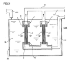
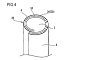
- the membrane distillation module of 1st Embodiment is shown, (A) is a vertical sectional view, (B) is an expansion perspective view of a hollow fiber membrane, (C) is a partial expanded sectional view of the focusing body of a hollow fiber membrane. It is a whole block diagram of the waste water treatment equipment provided with the said membrane distillation module. It is a whole block diagram which shows the modification of a waste water treatment equipment. It is a perspective view which shows 2nd Embodiment and shows the tubular porous membrane used for a membrane distillation module. A 3rd embodiment is shown, (A) is a conventional block diagram and (B) is a block diagram of the present invention.
- FIG. 1 shows a membrane distillation module according to a first embodiment of the present invention.
- the membrane distillation module 1 of the embodiment purifies high-temperature oil-containing wastewater by membrane distillation.
- the membrane distillation module 1 uses a hollow fiber membrane 2 shown in FIG. 1 (B) as a porous membrane for membrane distillation.
- the hollow fiber membrane 2 has an expanded PTFE porous membrane as a base membrane 3, and is a fluorine membrane having an oil repellent function in a mode in which the pores 3a (shown in FIG. 2) of the base membrane 3 are not closed on the outer peripheral surface of the base membrane 3.
- the oil-repellent layer 4 is provided by holding the solution made of a polymer having an alkylated side chain by impregnating the expanded PTFE porous membrane.
- the oil-repellent polymer used as the oil-repellent layer 4 may be any substance having an oil-repellent function, and is not limited to the polymer having the fluorinated alkyl side chain.
- the hollow fiber membrane 2 in which the oil repellent layer 4 is provided on the outer peripheral surface of the base membrane 3 is a porous membrane for membrane distillation with a mean pore size that does not allow water to permeate and allows only water vapor to permeate.
- the average pores are in the range of 0.01 ⁇ m to 1 ⁇ m.
- the hollow fiber membrane 2 has a treated liquid channel 5 in which the outer peripheral surface provided with the oil repellent layer 4 is in contact with the high-temperature oil-containing wastewater OL and the hollow portion is permeated through the membrane. .
- the inner diameter of the base film 3 serving as the treated liquid flow path 5 is 0.5 mm to 4 mm, the thickness is 10 ⁇ m to 5 mm, the porosity is 40 to 90%, and the tensile strength is 30 to 150 N.
- the membrane distillation module 1 includes a converging body 6 in which a plurality of hollow fiber membranes 2 are arranged at a required interval (0.5 mm to 20 mm).
- the upper and lower ends are fixed by upper and lower fixing plates 7 and 8 with the upper and lower openings 2a and 2b of each hollow fiber membrane 2 being opened.
- Caps 9 and 10 are fitted on the upper and lower fixing plates 7 and 8, respectively, and both ends of the circulating cooling pipe 11 are connected to the caps 9 and 10.
- the outer cylinder 15 which connects the said upper-and-lower fixing plates 7 and 8 is attached, and the converging body 6 is surrounded by opening the high-temperature oil-containing drainage circulation space 18.
- an intake port 15 a and a discharge port 15 b continuous with the drain circulation pipe 21 are provided.
- the cooling pipe 12 functions as a cooling pipe for cooling the high-temperature processed liquid.
- a drainage storage tank 20, a circulation pump 23, and a heater 22 are interposed in a drainage circulation pipe 21 that circulates the high-temperature oil-containing drainage OL.
- a plurality of membrane distillation modules 1 are arranged in the wastewater storage tank 20.
- the upper and lower fixing plates 7 and 8, the upper and lower caps 9 and 10, and the outer cylinder 25 are made of a heat-resistant resin or a metal material. Overall, it is excellent in alkali resistance.
- a cleaning apparatus for cleaning the membrane module 1 with a cleaning solution of an alkaline aqueous solution is attached.
- the high-temperature oil-containing wastewater OL that generates water vapor continuously supplied to the membrane distillation module 1 permeates through the hollow fiber membrane 2 made of a porous membrane only, and the water vapor enters the treated liquid channel 5 in the hollow portion.
- OS flows in.
- the steam OS flowing into the treated liquid flow path 5 rises and flows into the circulating cooling pipe 11 that continues upward. Since the circulation cooling pipe 11 is located in the atmosphere, the temperature is 20 ° C. to 40 ° C., and the water vapor is rapidly cooled in the circulation cooling pipe 11, and further, if necessary, the cooler 12 installed downstream is used.
- the liquid is cooled and liquefied, and stored in the cooling water tank 13.
- the cooling water in the cooling water tank 13 is taken out and reused, but a part of the cooling water is taken out by the circulation pump 14 and sent to the annular cooling pipe 11, and the hollow fiber membrane 2 is processed in a hollow state. It is preferable to rapidly cool by flowing into the spent liquid flow path 5 and bringing it into contact with water vapor passing through the hollow fiber membrane 2.
- the hollow fiber membrane 2 of the membrane distillation module 1 is provided with the oil repellent layer 4 on the outer peripheral surface in contact with the high-temperature oil-containing wastewater OL, so that the oil component is difficult to adhere and the pores of the hollow fiber membrane are blocked with the attached oil. Can be prevented, and the processing performance can be suppressed and prevented from being reduced.
- the high-temperature oil-containing wastewater OL purified by the membrane distillation module 1 can have a water-insoluble oil content of less than 1 mg / l when the oil component contains 200 mg / l or more.
- the high temperature oil-containing wastewater OL purified by the membrane distillation module 1 is particularly preferably used when the temperature is high enough to generate steam. When steam is not generated, it is supplied to the membrane distillation module 1 after being heated to a temperature at which steam is generated by a heater 22 interposed in the drain circulation pipe 21.
- FIG. 4 shows a membrane distillation module of the second embodiment.
- the hollow fiber membrane 2B used in the membrane distillation module is a tubular porous tube in which a PTFE porous sheet 30 is wound instead of using a hollow fiber made of PTFE as a base membrane, and the winding end is sealed and fixed.
- the film is used as the base film 3B.
- the oil repellent layer 4 is provided on the outer peripheral surface of the base film 3B as in the first embodiment, and the support layer 31 is provided by laminating a non-woven fabric on the inner peripheral surface.
- the cross-sectional area of the hollow portion that becomes the treated liquid flow path 5 can be made larger than that in the first embodiment.
- FIG. 5 shows a third embodiment.
- the drainage device equipped with the membrane distillation module 1 is a step of recovering bitumen from the oil sand disclosed in Japanese Patent Application Laid-Open No. 2010-248431 related to the prior application of the present applicant by the in-oil reservoir recovery method. Used.
- FIG. 5 (A) is a process diagram in which oil-containing water is reused by the flow according to the conventional SAGD method described in FIG. 7 of the above-mentioned JP 2010-248431 A.
- the heated oil-containing salt-containing wastewater supplied from the separator 40 to the skim tank 41 is purified by a purification device 45 surrounded by a frame, and then supplied to the boiler supply tank 42.
- the purification device 45 requires a multi-stage process for processing an inductive gas flotation, an oil removal filter, hot lime softening, and a weak acid cation ion exchanger.
- the purification device 45 is replaced with the wastewater treatment device 100A (or 100B) using one-step membrane distillation. Yes.
- a high-temperature oil-containing salt-containing wastewater is supplied from a separator 40 that separates by gravity to a wastewater treatment apparatus 100A from a skim tank 41, and a high-temperature oil-containing salt-containing salt is provided on the outer surface side of the porous membrane 2 of the membrane distillation module 1. Waste water is supplied, high temperature water is regenerated from the steam that has permeated through the porous membrane 2, and this purified high temperature water is supplied to the boiler supply tank 42.
- the multi-stage waste water purification treatment process can be performed in a single stage, and the equipment cost and running Cost can be greatly reduced.
- 1 membrane distillation module 1 hollow fiber membrane, 2 hollow fiber membrane, 3 base membrane, 4 oil repellent layer, 5 treated liquid flow path, 6 bundling body, OL oil-containing wastewater, OS treated liquid.
Landscapes
- Chemical & Material Sciences (AREA)
- Chemical Kinetics & Catalysis (AREA)
- Engineering & Computer Science (AREA)
- Water Supply & Treatment (AREA)
- Physics & Mathematics (AREA)
- General Engineering & Computer Science (AREA)
- High Energy & Nuclear Physics (AREA)
- Life Sciences & Earth Sciences (AREA)
- Hydrology & Water Resources (AREA)
- Environmental & Geological Engineering (AREA)
- Organic Chemistry (AREA)
- Separation Using Semi-Permeable Membranes (AREA)
Abstract
Description
該排水処理装置は、前記膜蒸留モジュールの排水流通側に排水循環管を連結し、該排水循環管を排水槽、循環ポンプおよび加熱器を介設する一方、前記膜蒸留モジュールの処理済み流体側に冷却水循環管を連結し、該冷却水循環管を冷却水槽、循環ポンプおよび冷却器を介設していることが好ましい。
図1に本発明の第1実施形態の膜蒸留モジュールを示す。
膜蒸留モジュール1は膜蒸留する多孔質膜として図1(B)に示す中空糸膜2を用いている。
なお、排水処理装置100A、100Bにおける膜蒸留の作用は同じであるため、図2の排水処理装置100Aに基づいて説明する。
該膜蒸留モジュールで用いる中空糸膜2Bは、基膜としてPTFE多孔質製の中空糸を用いる代わりに、PTFE多孔質シート30を巻回し、巻端をシール固着して筒状したチューブ状多孔質膜を基膜3Bとして用いている。該基膜3Bの外周面には1実施形態と同様に撥油層4を設ける一方、内周面に不織布を積層して支持層31を設けている。該チューブ状多孔質膜を基膜3Bとする場合、処理済み液流路5となる中空部の断面積は第1実施形態より大きくできる。
図5に第3実施形態を示す。
Claims (10)
- PTFE(ポリテトラフルオロエチレン)、PVDF(ポリフッ化ビニリデン)あるいはPCTFE(ポリクロロトリフルオロエチレン)の撥水性のあるフッ素樹脂からなると共に実用上の最高使用温度が80℃を越える耐熱性を有する疎水性多孔質膜からなる基膜の少なくとも一方の表面に、撥油機能を有する物質を複合固定化して撥油層を設けた多孔質膜を備えていることを特徴とする、膜蒸留モジュール。
- 前記基膜となる疎水性多孔質膜の気孔率が50%以上である、請求項1に記載の膜蒸留モジュール。
- 前記撥油機能を有する物質が、フッ素化アルキル側鎖を有する重合体から選択される少なくとも1種の高分子である、請求項1または請求項2に記載の膜蒸留モジュール。
- 前記疎水性多孔質膜は、(1)中空糸膜、(2)多孔質シートを巻回して巻端をシール固着して筒状としたチューブ状多孔質膜、または(3)多孔質シート単体あるいは不織布の異種材料の両面にラミネートされ、所定幅にスリットされた2枚の多孔質膜の両端を熱融着でシールしたものの内部にネットの流路材を含む袋状の複合膜からなる、請求項1乃至請求項3のいずれか1項に記載の膜蒸留モジュール。
- 前記撥油層を設けた外周面に高温排水の循環路を設ける一方、内周面に囲まれた中空部を冷却水の循環路としている、請求項1乃至請求項4のいずれか1項に記載の膜蒸留モジュール。
- 前記多孔質膜に蒸気のみを透過する排水は、オイル成分を200mg/l以上または運転温度以下で不揮発性でかつ水溶解性の低分子有機物または溶解性塩分を50,000mg/l以上含むものとしている、請求項1乃至請求項5のいずれか1項に記載の膜蒸留モジュール。
- 前記多孔質膜に蒸気のみを透過する排水は、放射性物質および油分を含む、請求項1乃至請求項6のいずれか1項に記載の膜蒸留モジュール。
- 前記排水は、SAGD法又はCSS法でオイルサンドから回収した加温ビチュメン混合流体からビチュメンを分離した後の高温含油排水である、請求項6に記載の膜蒸留モジュール。
- 請求項1乃至請求項8のいずれか1項に記載の膜蒸留モジュールを備えた排水処理装置。
- 前記膜蒸留モジュールの排水流路に排水循環管を連結し、該排水循環管に排水槽、循環ポンプおよび加熱器を介設する一方、前記膜蒸留モジュールの処理済み液流路に冷却水循環管を連結し、該冷却水循環管に冷却水槽、循環ポンプおよび冷却器を介設している、請求項9に記載の排水処理装置。
Priority Applications (2)
| Application Number | Priority Date | Filing Date | Title |
|---|---|---|---|
| US14/782,614 US20160038879A1 (en) | 2013-11-27 | 2014-11-26 | Membrane distillation module and wastewater treatment apparatus |
| CA2908904A CA2908904A1 (en) | 2013-11-27 | 2014-11-26 | Membrane distillation module and wastewater treatment apparatus |
Applications Claiming Priority (2)
| Application Number | Priority Date | Filing Date | Title |
|---|---|---|---|
| JP2013-245495 | 2013-11-27 | ||
| JP2013245495A JP2015100777A (ja) | 2013-11-27 | 2013-11-27 | 膜蒸留モジュールおよび排水処理装置 |
Publications (1)
| Publication Number | Publication Date |
|---|---|
| WO2015080125A1 true WO2015080125A1 (ja) | 2015-06-04 |
Family
ID=53199065
Family Applications (1)
| Application Number | Title | Priority Date | Filing Date |
|---|---|---|---|
| PCT/JP2014/081169 Ceased WO2015080125A1 (ja) | 2013-11-27 | 2014-11-26 | 膜蒸留モジュールおよび排水処理装置 |
Country Status (4)
| Country | Link |
|---|---|
| US (1) | US20160038879A1 (ja) |
| JP (1) | JP2015100777A (ja) |
| CA (1) | CA2908904A1 (ja) |
| WO (1) | WO2015080125A1 (ja) |
Cited By (8)
| Publication number | Priority date | Publication date | Assignee | Title |
|---|---|---|---|---|
| CN105106257A (zh) * | 2015-08-13 | 2015-12-02 | 南京中医药大学 | 一种提取柴胡挥发油的方法 |
| CN105174379A (zh) * | 2015-09-17 | 2015-12-23 | 刘志斌 | 一种反渗透系统的简易水循环结构 |
| CN106731852A (zh) * | 2017-03-20 | 2017-05-31 | 国家海洋局天津海水淡化与综合利用研究所 | 一种板式真空膜蒸馏蒸发器及应用 |
| WO2018174279A1 (ja) | 2017-03-24 | 2018-09-27 | 旭化成株式会社 | 膜蒸留用多孔質膜及び膜蒸留用モジュールの運転方法 |
| CN108597636A (zh) * | 2018-03-19 | 2018-09-28 | 南华大学 | 一种膜蒸馏技术处理放射性废水的方法和系统 |
| WO2020111158A1 (ja) | 2018-11-27 | 2020-06-04 | 旭化成株式会社 | 膜蒸留モジュール及び膜蒸留装置 |
| WO2020145401A1 (ja) | 2019-01-11 | 2020-07-16 | 旭化成株式会社 | 膜蒸留用モジュール及びそれを用いた膜蒸留装置 |
| WO2020246550A1 (ja) * | 2019-06-06 | 2020-12-10 | 東洋紡株式会社 | 膜蒸留用多孔質膜 |
Families Citing this family (10)
| Publication number | Priority date | Publication date | Assignee | Title |
|---|---|---|---|---|
| KR101692053B1 (ko) * | 2015-06-18 | 2017-01-17 | (주)세프라텍 | 막증류-결정화 시스템 및 방법 |
| US10239770B2 (en) | 2016-04-29 | 2019-03-26 | Kookmin University Industry Academy Cooperation Foundation | Multi-stage submerged membrane distillation water treatment apparatus |
| JP2018083189A (ja) * | 2016-05-24 | 2018-05-31 | 旭化成株式会社 | 膜蒸留装置 |
| JP7045138B2 (ja) * | 2016-05-27 | 2022-03-31 | 旭化成株式会社 | 油分混合水浄水システム |
| KR102111605B1 (ko) * | 2016-12-26 | 2020-05-15 | 주식회사 엘지화학 | 폐수 속 용매를 처리하는 방법 |
| CN111511460B (zh) * | 2017-12-27 | 2022-04-01 | 住友电气工业株式会社 | 含油废水处理用过滤膜和含油废水处理用过滤模块 |
| JPWO2020165956A1 (ja) * | 2019-02-12 | 2021-12-09 | 昭和電工マテリアルズ株式会社 | 膜蒸留用分離膜及び膜蒸留モジュール |
| EP3792934B1 (de) * | 2019-09-16 | 2022-01-12 | GNS Gesellschaft für Nuklear-Service mbH | Verfahren zur trocknung von transport- und/oder lagerbehältern und transport- und/oder lagerbehälter |
| CN112569796B (zh) * | 2020-12-30 | 2025-01-14 | 苏州苏净环保新材料有限公司 | 一种抗污染中空纤维膜组件 |
| CN119008064B (zh) * | 2024-09-30 | 2025-12-26 | 南华大学 | 双级非接触式膜蒸馏废水处理装置及其处理方法 |
Citations (5)
| Publication number | Priority date | Publication date | Assignee | Title |
|---|---|---|---|---|
| JPH04346823A (ja) * | 1991-05-27 | 1992-12-02 | Hitachi Ltd | 廃液の膜蒸発濃縮方法及び装置 |
| JPH067644A (ja) * | 1992-06-25 | 1994-01-18 | Hitachi Ltd | 膜蒸留装置 |
| JP2010075808A (ja) * | 2008-09-25 | 2010-04-08 | Toray Ind Inc | 淡水製造方法および淡水製造装置 |
| JP2010214245A (ja) * | 2009-03-13 | 2010-09-30 | Asahi Kasei Chemicals Corp | 官能基を有するグラフト鎖が固定された多孔膜、その製造方法および利用 |
| JP2013185127A (ja) * | 2012-03-09 | 2013-09-19 | Nitto Denko Corp | 油水分離方法、含油水の処理方法、ビチェーメンの生産方法およびそれらのシステム |
Family Cites Families (1)
| Publication number | Priority date | Publication date | Assignee | Title |
|---|---|---|---|---|
| US20130327711A1 (en) * | 2012-06-11 | 2013-12-12 | Great Salt Lakes Minerals Corporation | Methods for sustainable membrane distillation concentration of hyper saline streams |
-
2013
- 2013-11-27 JP JP2013245495A patent/JP2015100777A/ja active Pending
-
2014
- 2014-11-26 CA CA2908904A patent/CA2908904A1/en not_active Abandoned
- 2014-11-26 WO PCT/JP2014/081169 patent/WO2015080125A1/ja not_active Ceased
- 2014-11-26 US US14/782,614 patent/US20160038879A1/en not_active Abandoned
Patent Citations (5)
| Publication number | Priority date | Publication date | Assignee | Title |
|---|---|---|---|---|
| JPH04346823A (ja) * | 1991-05-27 | 1992-12-02 | Hitachi Ltd | 廃液の膜蒸発濃縮方法及び装置 |
| JPH067644A (ja) * | 1992-06-25 | 1994-01-18 | Hitachi Ltd | 膜蒸留装置 |
| JP2010075808A (ja) * | 2008-09-25 | 2010-04-08 | Toray Ind Inc | 淡水製造方法および淡水製造装置 |
| JP2010214245A (ja) * | 2009-03-13 | 2010-09-30 | Asahi Kasei Chemicals Corp | 官能基を有するグラフト鎖が固定された多孔膜、その製造方法および利用 |
| JP2013185127A (ja) * | 2012-03-09 | 2013-09-19 | Nitto Denko Corp | 油水分離方法、含油水の処理方法、ビチェーメンの生産方法およびそれらのシステム |
Cited By (19)
| Publication number | Priority date | Publication date | Assignee | Title |
|---|---|---|---|---|
| CN105106257A (zh) * | 2015-08-13 | 2015-12-02 | 南京中医药大学 | 一种提取柴胡挥发油的方法 |
| CN105174379A (zh) * | 2015-09-17 | 2015-12-23 | 刘志斌 | 一种反渗透系统的简易水循环结构 |
| CN106731852A (zh) * | 2017-03-20 | 2017-05-31 | 国家海洋局天津海水淡化与综合利用研究所 | 一种板式真空膜蒸馏蒸发器及应用 |
| CN106731852B (zh) * | 2017-03-20 | 2019-09-10 | 国家海洋局天津海水淡化与综合利用研究所 | 一种板式真空膜蒸馏蒸发器及应用 |
| TWI712448B (zh) * | 2017-03-24 | 2020-12-11 | 日商旭化成股份有限公司 | 膜蒸餾用多孔質膜及膜蒸餾用模組之運轉方法 |
| WO2018174279A1 (ja) | 2017-03-24 | 2018-09-27 | 旭化成株式会社 | 膜蒸留用多孔質膜及び膜蒸留用モジュールの運転方法 |
| KR20190117707A (ko) * | 2017-03-24 | 2019-10-16 | 아사히 가세이 가부시키가이샤 | 막 증류용 다공질 막 및 막 증류용 모듈의 운전 방법 |
| JPWO2018174279A1 (ja) * | 2017-03-24 | 2019-11-07 | 旭化成株式会社 | 膜蒸留用多孔質膜及び膜蒸留用モジュールの運転方法 |
| US11352270B2 (en) | 2017-03-24 | 2022-06-07 | Asahi Kasei Kabushiki Kaisha | Porous membrane for membrane distillation, and method for operating membrane distillation module |
| KR102285048B1 (ko) | 2017-03-24 | 2021-08-04 | 아사히 가세이 가부시키가이샤 | 막 증류용 다공질 막 및 막 증류용 모듈의 운전 방법 |
| CN108597636A (zh) * | 2018-03-19 | 2018-09-28 | 南华大学 | 一种膜蒸馏技术处理放射性废水的方法和系统 |
| WO2020111158A1 (ja) | 2018-11-27 | 2020-06-04 | 旭化成株式会社 | 膜蒸留モジュール及び膜蒸留装置 |
| US12194416B2 (en) | 2018-11-27 | 2025-01-14 | Asahi Kasei Kabushiki Kaisha | Membrane distillation module and membrane distillation apparatus |
| WO2020145401A1 (ja) | 2019-01-11 | 2020-07-16 | 旭化成株式会社 | 膜蒸留用モジュール及びそれを用いた膜蒸留装置 |
| JPWO2020145401A1 (ja) * | 2019-01-11 | 2021-09-27 | 旭化成株式会社 | 膜蒸留用モジュール及びそれを用いた膜蒸留装置 |
| AU2020206280B2 (en) * | 2019-01-11 | 2022-07-21 | Asahi Kasei Kabushiki Kaisha | Membrane distillation module and membrane distillation apparatus using same |
| JP7159353B2 (ja) | 2019-01-11 | 2022-10-24 | 旭化成株式会社 | 膜蒸留用モジュール及びそれを用いた膜蒸留装置 |
| US12285724B2 (en) | 2019-01-11 | 2025-04-29 | Asahi Kasei Kabushiki Kaisha | Membrane distillation module and membrane distillation apparatus using same |
| WO2020246550A1 (ja) * | 2019-06-06 | 2020-12-10 | 東洋紡株式会社 | 膜蒸留用多孔質膜 |
Also Published As
| Publication number | Publication date |
|---|---|
| JP2015100777A (ja) | 2015-06-04 |
| US20160038879A1 (en) | 2016-02-11 |
| CA2908904A1 (en) | 2015-06-04 |
Similar Documents
| Publication | Publication Date | Title |
|---|---|---|
| WO2015080125A1 (ja) | 膜蒸留モジュールおよび排水処理装置 | |
| CN110461452B (zh) | 膜蒸馏用多孔质膜和膜蒸馏用组件的运转方法 | |
| WO2015080123A1 (ja) | 排水処理方法、膜蒸留モジュールおよび排水処理装置 | |
| JP5446416B2 (ja) | 含油排水処理用の分離膜モジュール、含油排水処理方法および含油排水処理装置 | |
| Duong et al. | Highly permeable double-skinned forward osmosis membranes for anti-fouling in the emulsified oil–water separation process | |
| US20120103904A1 (en) | Separation membrane module for oil-containing wastewater treatment, oil-containing wastewater treatment method, and oil-containing wastewater treatment apparatus | |
| US11628408B2 (en) | Bilayer electrospun membranes for treating fracking wastewater via membrane distillation | |
| WO2015080124A1 (ja) | 排水処理方法、膜蒸留モジュールおよび排水処理装置 | |
| JP5418739B1 (ja) | 中空糸型半透膜及びその製造方法及びモジュール及び水処理方法 | |
| WO2013133043A1 (ja) | 油水分離方法、含油水の処理方法、ビチューメンの生産方法およびそれらのシステム | |
| KR101524225B1 (ko) | 막 증류용 분리막 모듈 | |
| JP2011200770A (ja) | 膜蒸留用多孔質膜、膜蒸留用モジュールおよび膜蒸留式造水システム | |
| WO2020111158A1 (ja) | 膜蒸留モジュール及び膜蒸留装置 | |
| JP2016097356A (ja) | 油水分離システム | |
| CN106865696B (zh) | 基于组合膜工艺的高温高盐采油废水回收再利用方法 | |
| JP2012130882A (ja) | 造水システム | |
| US11607649B2 (en) | Spiral wound membrane element for high temperature filtration | |
| Liu et al. | Membranes: technology and applications | |
| Chen et al. | Research on treatment of oily wastewater by membrane filtration | |
| JP2020175385A (ja) | 分離膜エレメント | |
| KR20190113216A (ko) | 막 젖음이 발생된 막 증류 모듈용 분리막의 성능 회복 방법 | |
| JP2014004497A (ja) | 造水装置 | |
| CN115279480A (zh) | 用于从含水材料去除污染物的方法和装置 | |
| US20160346738A1 (en) | Method and system for treating for produced water |
Legal Events
| Date | Code | Title | Description |
|---|---|---|---|
| 121 | Ep: the epo has been informed by wipo that ep was designated in this application |
Ref document number: 14866524 Country of ref document: EP Kind code of ref document: A1 |
|
| ENP | Entry into the national phase |
Ref document number: 2908904 Country of ref document: CA |
|
| WWE | Wipo information: entry into national phase |
Ref document number: 14782614 Country of ref document: US |
|
| NENP | Non-entry into the national phase |
Ref country code: DE |
|
| 122 | Ep: pct application non-entry in european phase |
Ref document number: 14866524 Country of ref document: EP Kind code of ref document: A1 |