WO2015080106A1 - 成分分析装置、薬効分析装置、及び分析方法 - Google Patents
成分分析装置、薬効分析装置、及び分析方法 Download PDFInfo
- Publication number
- WO2015080106A1 WO2015080106A1 PCT/JP2014/081135 JP2014081135W WO2015080106A1 WO 2015080106 A1 WO2015080106 A1 WO 2015080106A1 JP 2014081135 W JP2014081135 W JP 2014081135W WO 2015080106 A1 WO2015080106 A1 WO 2015080106A1
- Authority
- WO
- WIPO (PCT)
- Prior art keywords
- container
- amount
- buffer solution
- drug
- hepatocytes
- Prior art date
- Legal status (The legal status is an assumption and is not a legal conclusion. Google has not performed a legal analysis and makes no representation as to the accuracy of the status listed.)
- Ceased
Links
Images


Classifications
-
- B—PERFORMING OPERATIONS; TRANSPORTING
- B01—PHYSICAL OR CHEMICAL PROCESSES OR APPARATUS IN GENERAL
- B01L—CHEMICAL OR PHYSICAL LABORATORY APPARATUS FOR GENERAL USE
- B01L7/00—Heating or cooling apparatus; Heat insulating devices
-
- G—PHYSICS
- G01—MEASURING; TESTING
- G01N—INVESTIGATING OR ANALYSING MATERIALS BY DETERMINING THEIR CHEMICAL OR PHYSICAL PROPERTIES
- G01N33/00—Investigating or analysing materials by specific methods not covered by groups G01N1/00 - G01N31/00
- G01N33/48—Biological material, e.g. blood, urine; Haemocytometers
- G01N33/50—Chemical analysis of biological material, e.g. blood, urine; Testing involving biospecific ligand binding methods; Immunological testing
- G01N33/5005—Chemical analysis of biological material, e.g. blood, urine; Testing involving biospecific ligand binding methods; Immunological testing involving human or animal cells
- G01N33/5008—Chemical analysis of biological material, e.g. blood, urine; Testing involving biospecific ligand binding methods; Immunological testing involving human or animal cells for testing or evaluating the effect of chemical or biological compounds, e.g. drugs, cosmetics
- G01N33/5044—Chemical analysis of biological material, e.g. blood, urine; Testing involving biospecific ligand binding methods; Immunological testing involving human or animal cells for testing or evaluating the effect of chemical or biological compounds, e.g. drugs, cosmetics involving specific cell types
- G01N33/5067—Liver cells
-
- C—CHEMISTRY; METALLURGY
- C12—BIOCHEMISTRY; BEER; SPIRITS; WINE; VINEGAR; MICROBIOLOGY; ENZYMOLOGY; MUTATION OR GENETIC ENGINEERING
- C12M—APPARATUS FOR ENZYMOLOGY OR MICROBIOLOGY; APPARATUS FOR CULTURING MICROORGANISMS FOR PRODUCING BIOMASS, FOR GROWING CELLS OR FOR OBTAINING FERMENTATION OR METABOLIC PRODUCTS, i.e. BIOREACTORS OR FERMENTERS
- C12M25/00—Means for supporting, enclosing or fixing the microorganisms, e.g. immunocoatings
-
- C—CHEMISTRY; METALLURGY
- C12—BIOCHEMISTRY; BEER; SPIRITS; WINE; VINEGAR; MICROBIOLOGY; ENZYMOLOGY; MUTATION OR GENETIC ENGINEERING
- C12M—APPARATUS FOR ENZYMOLOGY OR MICROBIOLOGY; APPARATUS FOR CULTURING MICROORGANISMS FOR PRODUCING BIOMASS, FOR GROWING CELLS OR FOR OBTAINING FERMENTATION OR METABOLIC PRODUCTS, i.e. BIOREACTORS OR FERMENTERS
- C12M29/00—Means for introduction, extraction or recirculation of materials, e.g. pumps
-
- C—CHEMISTRY; METALLURGY
- C12—BIOCHEMISTRY; BEER; SPIRITS; WINE; VINEGAR; MICROBIOLOGY; ENZYMOLOGY; MUTATION OR GENETIC ENGINEERING
- C12M—APPARATUS FOR ENZYMOLOGY OR MICROBIOLOGY; APPARATUS FOR CULTURING MICROORGANISMS FOR PRODUCING BIOMASS, FOR GROWING CELLS OR FOR OBTAINING FERMENTATION OR METABOLIC PRODUCTS, i.e. BIOREACTORS OR FERMENTERS
- C12M41/00—Means for regulation, monitoring, measurement or control, e.g. flow regulation
- C12M41/46—Means for regulation, monitoring, measurement or control, e.g. flow regulation of cellular or enzymatic activity or functionality, e.g. cell viability
-
- C—CHEMISTRY; METALLURGY
- C12—BIOCHEMISTRY; BEER; SPIRITS; WINE; VINEGAR; MICROBIOLOGY; ENZYMOLOGY; MUTATION OR GENETIC ENGINEERING
- C12M—APPARATUS FOR ENZYMOLOGY OR MICROBIOLOGY; APPARATUS FOR CULTURING MICROORGANISMS FOR PRODUCING BIOMASS, FOR GROWING CELLS OR FOR OBTAINING FERMENTATION OR METABOLIC PRODUCTS, i.e. BIOREACTORS OR FERMENTERS
- C12M47/00—Means for after-treatment of the produced biomass or of the fermentation or metabolic products, e.g. storage of biomass
- C12M47/20—Heating or cooling
-
- G—PHYSICS
- G01—MEASURING; TESTING
- G01N—INVESTIGATING OR ANALYSING MATERIALS BY DETERMINING THEIR CHEMICAL OR PHYSICAL PROPERTIES
- G01N33/00—Investigating or analysing materials by specific methods not covered by groups G01N1/00 - G01N31/00
- G01N33/15—Medicinal preparations ; Physical properties thereof, e.g. dissolubility
-
- G—PHYSICS
- G01—MEASURING; TESTING
- G01N—INVESTIGATING OR ANALYSING MATERIALS BY DETERMINING THEIR CHEMICAL OR PHYSICAL PROPERTIES
- G01N33/00—Investigating or analysing materials by specific methods not covered by groups G01N1/00 - G01N31/00
- G01N33/48—Biological material, e.g. blood, urine; Haemocytometers
- G01N33/50—Chemical analysis of biological material, e.g. blood, urine; Testing involving biospecific ligand binding methods; Immunological testing
- G01N33/5005—Chemical analysis of biological material, e.g. blood, urine; Testing involving biospecific ligand binding methods; Immunological testing involving human or animal cells
- G01N33/5008—Chemical analysis of biological material, e.g. blood, urine; Testing involving biospecific ligand binding methods; Immunological testing involving human or animal cells for testing or evaluating the effect of chemical or biological compounds, e.g. drugs, cosmetics
- G01N33/502—Chemical analysis of biological material, e.g. blood, urine; Testing involving biospecific ligand binding methods; Immunological testing involving human or animal cells for testing or evaluating the effect of chemical or biological compounds, e.g. drugs, cosmetics for testing non-proliferative effects
-
- G—PHYSICS
- G01—MEASURING; TESTING
- G01N—INVESTIGATING OR ANALYSING MATERIALS BY DETERMINING THEIR CHEMICAL OR PHYSICAL PROPERTIES
- G01N35/00—Automatic analysis not limited to methods or materials provided for in any single one of groups G01N1/00 - G01N33/00; Handling materials therefor
- G01N35/10—Devices for transferring samples or any liquids to, in, or from, the analysis apparatus, e.g. suction devices, injection devices
- G01N35/1009—Characterised by arrangements for controlling the aspiration or dispense of liquids
-
- B—PERFORMING OPERATIONS; TRANSPORTING
- B01—PHYSICAL OR CHEMICAL PROCESSES OR APPARATUS IN GENERAL
- B01L—CHEMICAL OR PHYSICAL LABORATORY APPARATUS FOR GENERAL USE
- B01L3/00—Containers or dishes for laboratory use, e.g. laboratory glassware; Droppers
- B01L3/50—Containers for the purpose of retaining a material to be analysed, e.g. test tubes
- B01L3/508—Containers for the purpose of retaining a material to be analysed, e.g. test tubes rigid containers not provided for above
- B01L3/5085—Containers for the purpose of retaining a material to be analysed, e.g. test tubes rigid containers not provided for above for multiple samples, e.g. microtitration plates
-
- B—PERFORMING OPERATIONS; TRANSPORTING
- B01—PHYSICAL OR CHEMICAL PROCESSES OR APPARATUS IN GENERAL
- B01L—CHEMICAL OR PHYSICAL LABORATORY APPARATUS FOR GENERAL USE
- B01L9/00—Supporting devices; Holding devices
- B01L9/54—Supports specially adapted for pipettes and burettes
- B01L9/543—Supports specially adapted for pipettes and burettes for disposable pipette tips, e.g. racks or cassettes
-
- G—PHYSICS
- G01—MEASURING; TESTING
- G01N—INVESTIGATING OR ANALYSING MATERIALS BY DETERMINING THEIR CHEMICAL OR PHYSICAL PROPERTIES
- G01N35/00—Automatic analysis not limited to methods or materials provided for in any single one of groups G01N1/00 - G01N33/00; Handling materials therefor
- G01N2035/00346—Heating or cooling arrangements
- G01N2035/00425—Heating or cooling means associated with pipettes or the like, e.g. for supplying sample/reagent at given temperature
-
- G—PHYSICS
- G01—MEASURING; TESTING
- G01N—INVESTIGATING OR ANALYSING MATERIALS BY DETERMINING THEIR CHEMICAL OR PHYSICAL PROPERTIES
- G01N35/00—Automatic analysis not limited to methods or materials provided for in any single one of groups G01N1/00 - G01N33/00; Handling materials therefor
- G01N35/02—Automatic analysis not limited to methods or materials provided for in any single one of groups G01N1/00 - G01N33/00; Handling materials therefor using a plurality of sample containers moved by a conveyor system past one or more treatment or analysis stations
- G01N35/04—Details of the conveyor system
- G01N2035/0401—Sample carriers, cuvettes or reaction vessels
- G01N2035/0418—Plate elements with several rows of samples
Definitions
- the present invention relates to in vitro (in vitro) evaluation of pharmacokinetics such as drug uptake, metabolism, and excretion, which is useful for new drug development.
- the drug In order for the drug to exert its efficacy in the body, the drug once taken into the liver becomes a metabolite, or after being discharged to the blood vessel side without being metabolized as the original compound (parent compound) It is necessary to recirculate in the bloodstream and reach the target organ. Therefore, even in the in vitro test system, if we can measure the recirculation of drug candidate compounds excreted to the blood vessel side after administration and evaluate the efficacy, which is one of the most important indicators in new drug development, it will be a very useful drug. It can be a dynamic evaluation method.
- the entire pharmacokinetics image including the amount excreted from the cell as urine and feces after excretion of the bile duct, the amount excreted from the cell into the bile duct (disappearance), and the intracellular pool, to each fraction
- the distribution ratio can be obtained.
- Patent Document 1 and Patent Document 2 disclose a technique for evaluating a portion (disappearance) excreted from a bile duct of cells by administering a drug to cultured cells so far. This evaluation method evaluates the disappearance of the drug that is excreted into the bile duct without exhibiting toxicity or efficacy, and then excreted outside the body as urine or feces.
- the prior art is a method for evaluating the amount of gallbladder excretion, that is, the amount of a component having no medicinal effect, and a method for evaluating the disappearance from the body.
- it is desirable to directly evaluate the amount of components excreted on the blood vessel side, but in the prior art, there is no method for analyzing the amount of components excreted in blood vessels. It was not established.
- the administered drugs such as the vascular (Basal / Basolateral) drainage fraction, the luminal (Apical) drainage fraction, and the intracellular pool fraction of the administered drug
- a temperature adjustment unit that adjusts the temperature in the plurality of containers, and an analysis unit that measures a component in the plurality of containers and analyzes the measured component
- the plurality of containers include at least A first container and a second container, wherein the first container and the second container hold a first buffer solution, respectively, and the temperature adjusting unit is configured to control the temperature in the first container and the second container. Adjust so that the temperature in the container is different,
- the analysis unit includes the amount of the component discharged from the cells in the first container to the first buffer solution in the first container, and the cells in the first container from the cells in the second container.
- a component analyzer that measures the amount of the component discharged to the first buffer solution and analyzes the amount of the component discharged through the transporter of the cell.
- components such as drugs excreted on the blood vessel side of cells can be directly evaluated.
- the blood vessel (Basal / Basolateral) discharge fraction, the luminal (Apical) discharge fraction, and the intracellular residual fraction via the transporter and diffusion of drug candidate compounds (parent compound and metabolites) By quantifying and determining the total amount of drug candidate compounds administered and the distribution ratio to each fraction, it becomes possible to evaluate the dynamics of the administered drug candidate compounds. Among them, it is possible to improve in-vitro screening accuracy for drug candidates that exert their medicinal effects. As a result, drug candidate compounds can be narrowed down early, and unnecessary animal experiments and useless human clinical trials can be reduced. Contribute to reducing new drug development costs, which are a burden for pharmaceutical companies.
- Each test section has a holding area for holding cells.
- separate containers may be used for each test section, or a single container having a plurality of holding areas may be divided.
- Each test section may be set.
- Step 0 Preparation and culture of hepatocytes>
- hepatocytes are first prepared and cultured for verifying the effect of the drug. An example is shown below.
- Hepatocytes were prepared according to the in situ collagenase perfusion method. Details are as follows. Rats (5-6 weeks old) are laparotomized under pentobarbital anesthesia, a catheter is inserted into the portal vein, and preperfusion solution (Ca 2+ and Mg 2+ free, Hanks solution containing EGTA) is injected. . After confirming that blood removal from the liver is sufficient, stop perfusion. Replace the perfusate with the collagenase solution and perform perfusion. In this example, perfusion is performed using Hank's solution containing 0.05% collagenase, but this is not restrictive. After confirming that the intercellular tissue has been digested by collagenase, the perfusion is stopped.
- preperfusion solution Ca 2+ and Mg 2+ free, Hanks solution containing EGTA
- the liver is cut off, minced in cold Hanks solution, and dispersed to cells by pipetting. Use isotonic percoll solution to remove injured hepatocytes by centrifugation at 500G for 5 minutes.
- the survival rate of the obtained hepatocytes is measured by trypan blue exclusion method, and hepatocytes having a survival rate of 85% or more are used for culture.
- hepatocytes having a survival rate of 85% or more are used for the culture, but it goes without saying that the conditions are not necessarily limited thereto.
- the preparation of hepatocytes is not necessarily limited to the in situ collagenase perfusion method.
- the hepatocytes used are not limited to those derived from rats, and the strains of rats are not limited. Although hepatocytes are used in this embodiment, the present invention is not limited to this.
- hepatocytes prepared by the in situ collagenase perfusion method are suspended in a medium, and hepatocytes are suspended and seeded in a commercially available collagen-coated culture dish at a density of 5 ⁇ 10 5 cells / mL.
- the seeding density, medium, and culture plate 001 are not particularly limited.
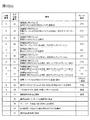
- the culture plate is shown in FIG. Here, a 24-well culture plate including 24 culture regions (wells, 002) is shown. However, the present invention is not limited to this, and other types of containers may be used as long as they can hold predetermined cells. After sowing, culture is started under conditions of 5% CO 2 and 37 ° C. using a CO 2 incubator. After more than 18 hours, perform the first medium change.
- the medium used for culturing after 18 hours after seeding is not particularly limited.
- Matrigel was added to a medium (hereinafter referred to as medium (FCS-)) obtained by removing FCS from the medium (10% FCS +). The added medium was used. Thereafter, the medium is changed every 24 hours using the medium (FCS-).
- FCS- medium
- step 5 in order to conduct tests under three different conditions in step 5 (test sections 1, 2, and 3: detailed in step 5), three culture plates under the same conditions are prepared independently at this point. To do. In Steps 0 to 4 and Step 5, the same test operation is performed in all three types of test sections.
- Step 1 Conditioning of hepatocytes>
- the cells cultured in step 0 are prepared for conditioning suitable for drug evaluation. An example is shown below.
- step 2 Remove the culture supernatant of cells cultured for 4 days in step 0, add 400 L of Hanks solution as a buffer, and incubate at 37 ° C. for 10 minutes (step 1 in FIG. 2).
- the type and amount of the buffer are not particularly limited.
- step 1 it is desirable to repeat step 1 twice.
- the buffer solution for example, Hank's solution
- Step 1 it is possible to prepare a groundwork for accurate measurement and analysis in the following steps. it can.
- how many times Step 1 is repeated may be arbitrarily changed according to the type of buffer solution to be used and the type of cells.
- Step 2 Drug administration>
- a drug solution to be evaluated is administered to the cells.
- An example is shown below.
- CDF fluorescent reagent
- the type, concentration and amount of the reagent are not particularly limited. Since CDF emits fluorescence, it can be easily quantified with a plate reader as a model reagent. Moreover, although the dosage was 200 ⁇ L, this was selected as the amount by which the entire cells in the well were immersed in the reagent.
- the concentration of CDF may be any concentration conventionally used as a cell fluorescence assay. It is desirable to apply this concentration as a reagent amount for detection with a plate reader.
- the incubation time was 30 minutes, which was adopted based on the result of a preliminary study that the time required for drug uptake and excretion to be almost in equilibrium was 30 minutes.
- the plate temperature was set to 4 ° C. after 30 minutes incubation. This is because, by lowering the temperature in the container, cells cause a phenomenon of suppressing discharge of the drug to the outside.
- the temperature of the drug is set to 4 ° C., but the temperature is not limited to this as long as the administered drug can be prevented from leaking out of the cell.
- the method is not limited to a method of lowering the temperature.
- the temperature in step 2 is lower than the plate temperature set in step 1. This is because, in the conditioning in the step 1, contrary to the step 2, a temperature (for example, 37 ° C.) that activates the phenomenon in which the cell absorbs and discharges the drug is desirable.
- the timing of drug administration is not limited to this example.
- drug administration may be performed from the day before or several days before the test day.
- the drug may be administered at the stage of step 0, and steps 1 and 2 may be omitted.
- Step 3 Cell washing>
- the parts other than the drug solution contained in the cells in step 3 are washed away. An example will be described below.
- step 3 in FIG. 2 The purpose of 4 ° C. is the same as described above.
- the amount of the culture medium during the culture was 400 ⁇ L
- the amount of the washing Hanks solution was 400 ⁇ L for the purpose of removing the medium components remaining on the inner wall of the well.
- the number of washings in a general biochemical assay is usually three times, and was followed. Each condition is not limited. Thereby, it becomes possible to remove other than the chemical solution to be measured, and to further improve the accuracy of the medicinal effect evaluation in the subsequent process.
- a pretreatment buffer solution for example, Hank's solution
- Hank's solution As the buffer solution, the same type of buffer solution used in step 5 may be used, or another type of buffer solution may be used.
- the drug stored in the hepatocytes (FIG. 3, 101) up to step 3 is discharged into the Hanks solution via the first blood vessel, that is, via passive diffusion (FIG. 2, step 4, (1) ′) and trans In order to discharge through the porter (TP) (step 4 in FIG. 2, (2) ′ and 102 in the image diagram), the temperature was maintained at 37 ° C.
- the blood vessel side discharge in the step 4 is defined as the first blood vessel side discharge and the blood vessel side discharge in the step 5 is defined as the second blood vessel side discharge.
- both are steps of discharging from the cell to the blood vessel side (Basal / Basolateral) (supernatant).
- a transporter is a membrane protein responsible for transporting a substance expressed on a cell membrane. Responsible for active mass transport inside and outside the cell. Moreover, passive diffusion is the discharge
- the drug discharged into the Hanks solution in Step 4 was defined as the blood vessel side drainage fraction.
- the upper surface portion of the cell facing the Hanks solution was the Basal / Basolateral surface (FIGS. 3 and 104). This is because it is assumed in the living body that the portion faces the blood vessel.
- Step 5 to be described next is a step of collecting the drug by three different types of operations (test sections 1, 2, and 3), but before step 5, the first blood vessel as described above in step 4 is performed.
- the side discharge fraction the drug discharged into the Hanks solution
- the Hanks solution used for grasping each part of the blood vessel side discharge may be the Hanks solution of any test section.
- all of the Hanks solutions in test sections 1 to 3 described later may be evaluated, or only a part may be used.
- steps 3 and 4 are steps for performing the analysis according to the present invention in more detail and performing a highly accurate evaluation, and it is needless to say that the step 5 can be performed by skipping the present invention.
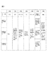
- Steps 0 to 4 are performed at least in the test sections 1 to 3, as shown in FIG.
- step 5 the test sections 1 to 3 are processed under different conditions in order to obtain a plurality of index data obtained in the present invention by analysis described later. An example is shown below.
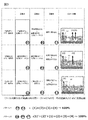
- test section 1 collection of supernatant by 37 ° C. disintegration system>
- test group 1 as shown in test group 1 of FIG. 3, bile duct side discharge (3) and second blood vessel side discharge (that is, diffusion (1) ) And transporter (TP) (discharged from (2)).
- the Hanks (-) solution is a Hanks solution that does not contain calcium ions or magnesium ions, and is used when the intercellular adhesion intention is not strengthened as in this test section.
- a chelator such as EGTA is used as described below.
- 200 ⁇ L of Hanks ( ⁇ ) solution containing 1 mM EGTA was added.
- EGTA has a chelating action to suppress the action of Ca 2+ and Mg 2+ involved in the adhesion of intercellular adhesion molecules, and is a reagent for releasing the adhesion between cells. This disrupts the bile duct formed in the culture process. After incubation at 37 ° C. for 30 minutes, the supernatant was collected.
- the reagent is not limited to EGTA as long as it has a chelating action.
- the type, amount, and incubation temperature and time of the buffer containing EGTA are not particularly limited. In the test zone 1 of the process 5, the drug stored in the cell at the stage where the process 4 is completed (the process 5 in FIG.
- step 5 was defined as the biliary effluent fraction because the cell membrane part around the gap formed in the intercellular adhesion part corresponds to the apical surface (Fig. 3, 105) and the gap This is because it is assumed in the capillary bile duct (FIG. 3, 103).
- process 5 test group 1 the temperature is maintained at 37 ° C., so that the fraction discharged from the cell to the blood vessel side is routed via passive diffusion (step 5, (1) in FIG. 3) and via the transporter ( 3 includes step 5 and (2)).
- test section 2 collection of supernatant by 37 ° C. maintenance system>
- the test group 2 does not collapse the bile duct as in the test group 1, but discharges only the second blood vessel side discharge (diffusion (1) and transporter (2)) shown in FIG.
- test group 2 is a test group that does not contain a chelating agent such as EGTA, so that cell-cell adhesion remains maintained, and therefore capillary bile duct collapse is not induced. After incubation at 37 ° C. for 30 minutes, the supernatant was collected.
- the drug FIG. 3, step 5 and image diagrams (1) and (2) stored in the cells at the stage where step 4 is completed is discharged into the supernatant and collected.
- step 5 test section 2 the drug discharged into the supernatant is defined as the second blood vessel side discharge fraction.
- the temperature is maintained at 37 ° C., so that the fraction discharged from the cell to the blood vessel side is routed via passive diffusion (step 5, (1) in FIG. 3) and via the transporter ( 3 includes step 5 and (2)).
- the drug recovered in test zone 2 from the value obtained by quantifying the amount of drug collected in test zone 1 By subtracting the value obtained by quantifying the amount, it is possible to calculate the amount of medicine for bile duct side discharge (3) and the amount of drug for second blood vessel side discharge, respectively.
- test section 3 collection of supernatant by 4 ° C. maintenance system>
- the test group 3 suppresses the drug discharged from the transporter (1) out of the second blood vessel side discharge by setting the temperature condition to be lower than that of the test groups 1 and 2, as will be described later, and the diffusion (2) Only the discharge due to is discharged.
- test temperature is different from the process 5 test section 2 of the same maintenance system. This is to suppress blood vessel side discharge via the transporter by setting the temperature to 4 ° C.
- a low temperature 4 ° C test zone that suppresses the transporter activity in the test zone 5 of the process 5
- only the amount of discharge via passive diffusion is quantified (Fig. 3, step 5, (1)).
- Each drug has a specific transporter that moves inside and outside the cell.
- the ability to quantify the discharge amount via the transporter while eliminating the discharge amount via the passive diffusion means that the discharge amount can be quantified specifically for each drug.
- the type, amount, and incubation temperature and time of the buffer are not particularly limited.
- the fraction discharged from the transporter can be calculated from the test group 2 and the test group 3 in step 5 by quantifying the recovered drug.
- the discharge fractions are calculated using the test sections 1, 2, and 3, respectively, but the number of test sections is not necessarily three.
- Step 6 Collection of bile duct fraction and intracellular fraction>
- the operation returns to the common operation in all three test sections.
- the drug for quantifying the intracellular residual fraction is collected.
- Hank's solution containing 1% of a surfactant for example, 200 ⁇ L
- the obtained sample was transferred to a culture plate, and fluorescence measurement was performed using a plate reader. Prepare wells containing only Hanks solution for blank measurement. The fluorescence intensity is measured at an excitation wavelength of 484 nm and an absorption wavelength of 519 nm.
- LCMS mass spectrometry
- the following drug-specific scoring is possible.
- an example of the calculated CDF score is shown.
- the calculated score is not limited to these.
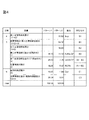
- the score for assessing vascular drainage via the transporter is -It is obtained by (B2-B3) / B2 as the ratio of the amount of drug discharged via the transporter to the amount of discharged drug on the second blood vessel side (Ratio of Extracellular Efflux by Diffusion, RexEMTP).
- the score for evaluating excretion into the bile duct is (B1-B2) / (C1 + C2) as a ratio of biliary excretion drug amount (Biliary Retention Drug, BiRD) to the total drug amount taken up into cells Or another way,
- the ratio of the amount of drug excreted in the bile duct to the amount of drug remaining in the cell is (C2-C1) / C2 or (B1-B2) / C1 Etc.
- the ratio of the amount of drug discharged via the transporter to the blood vessel side discharged drug amount of CDF (RexEMTP) and the ratio of the amount of bile duct excreted drug to the total amount of drug taken into cells (BiRD) are 41.08 and 18.58, while those of Rhodamine 123 are 52.52 and 4.92, indicating that CDF is more easily excreted in the bile duct than Rhodamine 123 and is less likely to be excreted on the blood vessel side.
- Example 2 describes a case where a method different from that in Example 1 is used for determination of the distribution ratio to each fraction and scoring based on the measurement result.
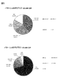
- the distribution ratio to each section as shown in pattern 2 in FIG. 4 is obtained from the nine types of values obtained by the fluorescence amount measurement. From these values, The first blood vessel side discharge fraction (Sup fraction) is S1 ( ⁇ S2 ⁇ S3), ⁇ Extracellular Efflux by Diffusion (ExEfx-Dif) is B3. ⁇ Extracellular Efflux by Transporter (ExEfx-TP) only via the transporter is B2-B3, ⁇ Bile duct side fraction (Bile Canaliculi Efflux, BCEfx) is B1-B2, -Intracellular residual fraction (Cell) is C1 It is corresponded to. Based on this result, a pie chart such as pattern 2 in FIG.
- Example 5 can be drawn, and the overall distribution ratio image for each fraction can be visually understood.
- Sup fraction which is an indicator of whether or not to remain in the cell, is 70.82 in CDF, and 39.29 in Rhodamine 123 (FIG. 6, pattern 2). It can be seen that CDF tends to be easily discharged to the blood vessel side. This is consistent with the intracellular residual fraction evaluation of Example 1.
- Example 3 describes an example of an apparatus that realizes automation of the series of steps described in Examples 1 and 2.
- description may be abbreviate
- a plurality of containers of the above-mentioned “well culture plate” may be set for each test section, or within one well culture plate.
- the plurality of wells may be divided, and for example, “first container”, “second container”, “third container”, or the like may be set for each divided region.
- test group 1 well and the test group 2 well perform the same temperature control, so that it is possible to evaluate more efficiently from the viewpoint of accuracy and speed by setting one well culture plate inside. Become.
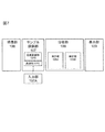
- the apparatus includes a culture unit 106, a sample preparation unit 107 (including an input unit 107A), an analysis unit 108, and a display unit 109. Further, the sample preparation unit 107 includes a temperature adjustment unit 107B that adjusts the temperature in each container (plate), which will be described later, and a liquid feeding unit 107C that can supply or recover the liquid to the container.
- the analysis unit 108 measures the amount of a component such as a drug and the amount of the component such as the drug acquired from the measurement unit, and discharges from the transporter, via the bile duct, remaining in the cell, and from other than the transporter and the bile duct There is an analysis unit 108B that analyzes each amount of the amount (diffusion).
- the above apparatus configuration is an example, and it goes without saying that, for example, only the analysis unit may be executed by another apparatus, and the information acquired from the measurement unit may be transmitted to the other apparatus.
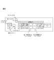
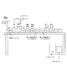
- the detailed configuration of the sample preparation unit is shown in FIGS.
- the purpose of the sample preparation unit is to automatically prepare each fraction to be analyzed as described in Example 1-2.
- Each component will be described in accordance with a flowchart described later.
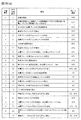
- the automatic measurement device operation flowchart is shown in FIG.
- the flowchart in FIG. 10 is merely an example, and this is not the case when the timing of drug administration is different as described in Example 1 ⁇ Step 2>.
- a container for holding cells will be described using a plate having a plurality of cell holding regions (wells) as an example.
- the container is not limited to a plate, and can hold cells. It goes without saying.
- hepatocytes are cultured in the culture unit 106 (FIGS. 7 and 10) (FIG. 10A, sub-step 1). Thereafter, the plate holding the cultured hepatocytes is transferred onto the plate holder 210 with the first temperature control function and the plate holder (211) with the second temperature control function of the sample preparation unit (FIGS. 7 and 10). (FIG. 10 (a) Sub-step 2).
- Example preparation equivalent to step 1 of Examples 1 and 2>
- a suction head 205 provided with a suction nozzle for sucking a liquid installed in the liquid feeding unit 107C moves to the well 002 of the culture plate 001 filled with the medium to be removed on the plate holder. Then, the medium is aspirated from the wells to remove the whole amount (substep 3 in FIG. 10). The removed medium is discarded and collected in the waste liquid tank 206.
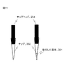
- the chip 302 holding the liquid 301 is mounted on the chip head 204 attached to the suction nozzle from the chip rack 207 in which a plurality of chips are stored.
- the chip head moves to the room temperature chemical rack 209 and sucks the buffer (substep 4 in FIG. 10).
- the chip head moves to the dust box 214, and the chip is discarded.
- a replaceable chip is used here, but this is not the case.
- the suction head moves to the well filled with the buffer and removes the buffer (FIG. 10 (a), sub-step 6).
- the removed medium is discarded and collected in the waste liquid tank 206. This process is repeated twice in total (cleaning process) (FIG. 10A, sub-process 7).
- the chip in the chip rack 207 is mounted on the chip head 204, the chip head moves to the room temperature chemical rack 209, and the buffer is sucked (substep 8 in FIG. 9). After moving to the target well and adding the buffer, the chip head moves to the dust box 214 and the chip is discarded. Wait for 10 minutes at 37 ° C. (conditioning) (FIG. 10A, sub-step 9). Thereafter, the suction head 205 moves to the well filled with the buffer, and removes the entire amount of the buffer (FIG. 9A, sub-step 10).
- Example preparation equivalent to step 2 in Examples 1 and 2>
- the chip in the chip rack 207 is mounted on the chip head 204, the chip head moves to the room temperature chemical rack 209, and sucks the chemical (substep 11 in FIG. 10 (a)).
- the chip head 204 moves to the dust box 214, and the chip is discarded. Wait for 30 minutes at 37 ° C. (FIG. 10A, sub-step 12).
- the plate holder 210 with a 1st temperature control function and the plate holder 211 with a 2nd temperature control function which are one structural example of the container holding part holding a container change from 37 degreeC to 4 degreeC (FIG.
- the suction head 205 moves to the well filled with the chemical solution, and removes the entire amount of the chemical solution (FIG. 10 (a) sub-step 14).
- the temperature adjustment unit is described as having a temperature adjustment function mounted on the plate folder, but it goes without saying that the temperature adjustment unit may exist separately from the container holding unit.
- Example preparation equivalent to step 3 in Examples 1 and 2>
- the chip in the chip rack 207 is mounted on the chip head 204, the chip head moves to the refrigerated chemical rack 208, and the buffer is sucked (substep 15 in FIG. 10 (a)).
- the refrigerated chemical solution is used to stop an active life phenomenon such as transporter activity.
- the refrigerated chemical rack 208 is used to keep chemicals, buffers and the like at a low temperature.
- the chip head 204 moves to the dust box 214, and the chip is discarded.
- the suction head moves to the well filled with the buffer, and the buffer is removed (FIG. 10A, sub-step 17).
- the removed medium is discarded in the waste liquid tank 206. This process is repeated three times in total (cleaning process) (FIG. 10 (a) sub-process 18).
- Example preparation equivalent to step 4 in Examples 1 and 2>
- the chip head 204 has the inside of the chip rack 207.
- the chip is mounted, the chip head moves to the refrigerated drug solution rack 208, and the buffer is sucked (FIG. 10A, sub-step 20).
- the chip head 204 moves to the dust box 214 and discards the chip. Wait for 30 minutes at 37 ° C. (FIG. 10A, sub-step 20).
- the chip rack 207 is mounted on the chip head 204.
- the chip inside is mounted, moved to a well filled with a buffer containing the drug, the buffer (supernatant) containing the drug is aspirated, and recovery for recovery on the first plate holder 212 and the second plate holder 213 is performed.
- Dispensing into a plate (collection) (FIG. 10 (a) sub-step 23).
- Example preparation equivalent to step 5 in Examples 1 and 2>
- the chip in the chip rack 207 is mounted on the chip head 204, and the chip head is placed in the room temperature chemical rack ( 209), the buffer containing EGTA is sucked (FIG. 10 (a) sub-step 24).
- the chip head 204 moves to the dust box 214 and discards the chip. . Wait for 30 minutes at 37 ° C. (FIG. 10B, sub-step 26).
- the chip in the chip rack 207 is mounted on the chip head 204, the chip head moves to the room temperature chemical rack 209, and the buffer is sucked (sub-step 27 in FIG. 10 (b)). After moving to the well for test section 2 on the first plate holder 212 and adding the buffer (FIG. 10B, sub-step 28), the chip head 204 moves to the dust box 214, and the chip is discarded. Wait for 30 minutes at 37 ° C. (FIG. 10B, sub-step 28).
- the chip in the chip rack 207 is mounted on the chip head 204, the chip head moves to the refrigerated chemical solution rack 209, and the buffer is sucked (substep 29 in FIG. 10 (b)).
- the chip in the chip rack 207 is mounted on the chip head 204, moved to a well filled with the EGTA buffer containing the drug, the EGTA buffer (supernatant) containing the drug is sucked, and collected on the first plate holder 212 Are dispensed (collected) onto the collecting plate (FIG. 10 (b) sub-step 31).
- the chip in the chip rack 207 is mounted on the chip head 204, moved to a well filled with a buffer containing a drug, the buffer (supernatant) containing the drug is sucked, and the recovery for recovery on the first plate holder 212 is performed. Dispensing (collecting) the plate (FIG. 10 (b), sub-step 32).
- a chip in the chip rack 207 is mounted on the chip head 204, moved to a well filled with an EGTA buffer containing a drug, a buffer (supernatant) containing the drug is sucked, and a recovery plate on the first plate holder 213 is collected. It dispenses (collects) to the collection plate (FIG. 10 (b) sub-step 33).
- the chips in the chip rack 207 are mounted on the chip head 204. Then, the chip head moves to the room temperature chemical rack 209 and sucks 1% Triton X-100 or pure water / methanol (FIG. 10 (b), sub-step 35). Move to the wells for test zones 1, 2, and 3 on the plate holder (210) with the first temperature control function and the plate holder 211 with the second temperature control function, and add 1% Triton X-100 or pure water / methanol. After the addition (FIG. 10B, sub-step 36), the chip head 204 moves to the dust box 214, and the chip is discarded.
- a chip in the chip rack 207 is mounted on the chip head 204, moved to a well filled with the reagent, and the whole cell suspension is aspirated and collected on the first plate holder 212 and the second plate holder 213. (Collecting) (collection) (FIG. 10 (b) sub-step 37).
- a holding unit that holds a plurality of containers that hold predetermined cells, a temperature adjustment unit that adjusts the temperature in the plurality of containers, and a component in the plurality of containers are measured, and the measured component is analyzed
- An analysis unit and The plurality of containers are at least a first container and a second container, wherein the first container and the second container each hold a first buffer solution, and the temperature adjusting unit is in the first container.
- the analysis unit is discharged from the cells in the first container to the first buffer solution in the first container.
- the amount of the component discharged from the cells in the second container to the first buffer solution in the second container is measured and discharged through the cell transporter.
- a component analysis apparatus that analyzes the amount of the component.
- the predetermined cell is a hepatocyte
- the plurality of containers are at least the first container, the second container, and the third container, and a predetermined substance is added to the third container.
- the second buffer solution is retained,
- the temperature adjustment unit adjusts the second temperature in the second container to be lower than the first temperature in the first container and the third container, and the analysis unit
- the amount of components discharged from the hepatocytes in one container to the first buffer solution in the first container, and from the hepatocytes in the second container to the first buffer solution in the second container The amount of the discharged component and the amount of the component discharged from the hepatocytes in the third container to the second buffer solution in the third container are measured, and the hepatocyte transporter
- the component analysis apparatus according to Configuration
- the liquid supply section further supplies or recovers the liquid in the plurality of containers, and the liquid supply section supplies the component solution containing the component to the plurality of containers, and collects the component solution.
- 3 buffer solutions are supplied into the plurality of containers, and after the third buffer solution is recovered, the first buffer solution is supplied to the first container and the second container, and the second container is supplied to the second container.
- a buffer solution is supplied, and the analysis unit measures the amount of a component discharged from the hepatocytes held in any of the plurality of culture vessels into the third buffer solution.
- the temperature adjusting unit adjusts the temperature so that the temperature in at least one of the plurality of containers when the third buffer solution is held is lower than the first temperature.
- the analysis unit includes an amount of the component remaining in the hepatocyte in the third container and a component remaining in the hepatocyte in at least one of the first container and the second container.
- a holding unit that holds a plurality of containers that hold hepatocytes that have absorbed the drug; a liquid feeding unit that supplies liquid in the plurality of containers; a temperature adjustment unit that adjusts the temperature in the plurality of containers; An analyzer that measures the amount of medicine in a plurality of containers and analyzes the measured medicine, wherein the plurality of containers are a first container, a second container, and a third container, The unit supplies a first buffer solution to the first container and the second container, and supplies a second buffer solution that promotes the discharge of the drug from the hepatocyte capillaries to the third container.
- the temperature adjustment unit adjusts the temperature so that the temperature in the second container is lower than the temperature in the first container and the third container
- the analysis unit The amount of the drug excreted from the hepatocytes in one container into the first buffer solution, and the second volume.
- a drug component analyzing apparatus characterized in that
- a holding unit that holds a plurality of containers that hold hepatocytes that have absorbed the drug; a liquid feeding unit that supplies or discharges liquid in the plurality of containers; and a temperature adjustment unit that adjusts the temperature in the plurality of containers;
- An analysis unit that measures the amount of the drug in the plurality of containers and analyzes the measured drug, and the liquid feeding unit supplies the drug to the plurality of containers, After discharging from the plurality of containers, a pretreatment buffer solution is supplied, and after the pretreatment buffer solution is recovered from the plurality of containers, the first container and the second container among the plurality of culture containers
- a first buffer solution is supplied to the third container, and a second buffer solution for urging the medicine to be discharged from the capillary bile duct of the hepatocytes is supplied to the third container, and the temperature adjusting unit is connected to the first container.
- the second container than the first temperature inside and the third container Toward the second temperature is the temperature adjusted to be lower, and
- the analysis unit is discharged from the hepatocytes in the plurality of containers into the pretreatment buffer solution, and from the hepatocytes in the first container into the first buffer solution.
- the amount of the drug, the amount of the drug discharged from the hepatocytes in the second container into the first buffer solution, and the drained from the hepatocytes in the third container into the second buffer solution The amount of the drug, the amount of the drug excreted from the hepatocytes in the pretreatment of the hepatocytes, the amount of the drug excreted from the transporter of the hepatocytes, and the capillary bile duct of the hepatocytes
- the drug component analyzer is characterized by analyzing the amount of the drug discharged from the liver and the amount of the drug discharged from other than the hepatocyte transporter and capillary bile duct.
- ⁇ Configuration 9> 9. The drug component analyzer according to Configuration 8, wherein the pretreatment buffer solution and the first buffer solution are the same type of buffer solution.
- the temperature adjusting unit adjusts the temperature so that the first temperature is higher than the temperature in at least one of the plurality of containers when the pretreatment buffer solution is held.
- the drug component analyzer according to configuration 8, wherein the drug component analyzer is adjusted.
- the analysis unit includes an amount of the component remaining in the hepatocyte in the third container and a component remaining in the hepatocyte in at least one of the first container and the second container. And measuring the amount of the remaining component other than the capillaries of the hepatocytes and analyzing the amount of the remaining component.
- the cell is a hepatocyte, and a second buffer solution to which a predetermined substance is added is held in the third container in which the hepatocyte is held.
- the first container Adjusting the second temperature in the second container to be lower than the first temperature in the inner container and the third container, and in the measurement step, the hepatocytes in the first container
- the amount of the component discharged into the first buffer solution in one container, the amount of the component discharged from the hepatocytes in the second container into the first buffer solution in the second container, and the The amount of the component discharged from the hepatocytes in the third container to the second buffer solution in the third container is measured, and in the analysis step, the amount is discharged via the hepatocyte transporter.
- the amount of the component and the hepatocyte excreted through the capillary bile duct And minute amounts a structure 12 component analysis method, wherein said the amount of the components discharged from the non-transporter and bile canaliculi of liver cells, respectively analysis.
- the liquid supply step further includes a liquid supply step of supplying or recovering liquid in a plurality of containers including at least the first container, the second container, and the third container.
- the component solution containing the component is supplied to the plurality of containers, and after the component solution is recovered, the third buffer solution is supplied into the plurality of containers and the third buffer solution is recovered, The first buffer solution is supplied to the first vessel and the second vessel, the second buffer solution is supplied to the third vessel, and held in at least one of the plurality of culture vessels in the measurement step.
- the component distribution method according to Configuration 13 wherein the amount of the component discharged from the hepatocyte into the third buffer solution is analyzed.
- ⁇ Configuration 16> Prior to the temperature adjustment step, the temperature in at least one of the plurality of containers when the third buffer solution is held is lower than the first temperature. 15.
- a liquid feeding step for supplying liquid to a plurality of containers holding hepatocytes that have absorbed the drug, a temperature adjustment step for adjusting the temperature in the plurality of containers, and the amount of the drug in the plurality of containers are measured.
- a measurement step and an analysis step for analyzing the drug measured in the measurement step wherein the plurality of containers are a first container, a second container, and a third container, and the first step in the liquid feeding step Supplying a first buffer solution to the container and the second container; supplying a second buffer solution for urging the medicine to be discharged from the capillary bile duct of the hepatocytes; And adjusting the temperature so that the temperature in the second container is lower than the temperature in the first container and the third container, and in the measuring step, the hepatocytes in the first container Amount of the drug discharged from the first buffer solution from The amount of the drug discharged from the hepatocytes in the second container into the first buffer solution, and the amount of the drug discharged from the hepatocytes in the third container into the second buffer solution; The amount of the component remaining in the hepatocytes in the third container, the amount of the component remaining in the hepatocytes in at least one of the first container and the second container, In the analysis step, the
- the drug is supplied to the plurality of containers, and the drug is discharged from the plurality of containers. Then, after supplying the pretreatment buffer solution and recovering the pretreatment buffer solution from the plurality of containers, the first buffer and the second container among the plurality of culture vessels are supplied to the first buffer.
- a second buffer solution for urging the drug to be discharged from the hepatocyte capillary bile duct is supplied to the third container.
- the first container and the third container are supplied. Than the first temperature in the container. The temperature is adjusted so that the second temperature in the two containers is lower, and in the measurement step, the amount of the drug discharged from the hepatocytes in the plurality of containers into the pretreatment buffer solution, The amount of the drug discharged from the hepatocytes in the first container into the first buffer solution, and the amount of the drug discharged from the hepatocytes in the second container into the first buffer solution; The amount of the drug discharged from the hepatocytes in the third container into the second buffer solution, the amount of the component remaining in the hepatocytes in the third container, and the first container or The amount of the component remaining in the hepatocytes in at least one of the second containers is measured, and in the analysis step, the hepatocytes are discharged from the hepatocytes in the pretreatment
- the first temperature is higher than the temperature in at least one of the plurality of containers when the pretreatment buffer solution is held.
Landscapes
- Health & Medical Sciences (AREA)
- Life Sciences & Earth Sciences (AREA)
- Engineering & Computer Science (AREA)
- Chemical & Material Sciences (AREA)
- Bioinformatics & Cheminformatics (AREA)
- Biomedical Technology (AREA)
- Immunology (AREA)
- Zoology (AREA)
- Wood Science & Technology (AREA)
- Organic Chemistry (AREA)
- Biochemistry (AREA)
- General Health & Medical Sciences (AREA)
- Biotechnology (AREA)
- Microbiology (AREA)
- Molecular Biology (AREA)
- Analytical Chemistry (AREA)
- Cell Biology (AREA)
- Hematology (AREA)
- Urology & Nephrology (AREA)
- Sustainable Development (AREA)
- General Engineering & Computer Science (AREA)
- Genetics & Genomics (AREA)
- General Physics & Mathematics (AREA)
- Physics & Mathematics (AREA)
- Pathology (AREA)
- Medicinal Chemistry (AREA)
- Food Science & Technology (AREA)
- Toxicology (AREA)
- Tropical Medicine & Parasitology (AREA)
- Clinical Laboratory Science (AREA)
- Pharmacology & Pharmacy (AREA)
- Biophysics (AREA)
- Gastroenterology & Hepatology (AREA)
- Chemical Kinetics & Catalysis (AREA)
- Measuring Or Testing Involving Enzymes Or Micro-Organisms (AREA)
- Investigating Or Analysing Biological Materials (AREA)
- Apparatus Associated With Microorganisms And Enzymes (AREA)
Priority Applications (8)
| Application Number | Priority Date | Filing Date | Title |
|---|---|---|---|
| CN201480040060.4A CN105378053B (zh) | 2013-11-29 | 2014-11-26 | 成分分析装置、药效分析装置和分析方法 |
| CN201710860736.XA CN107513550B (zh) | 2013-11-29 | 2014-11-26 | 成分分析方法 |
| US14/914,278 US9880153B2 (en) | 2013-11-29 | 2014-11-26 | Componential analyzer, drug efficacy analyzer, and analysis method |
| EP17186423.4A EP3272852B1 (en) | 2013-11-29 | 2014-11-26 | Componential analyzer, drug efficacy analyzer, and analysis method |
| EP20154632.2A EP3712245B1 (en) | 2013-11-29 | 2014-11-26 | Componential and drug efficacy analysis method |
| EP14866627.4A EP3023489B1 (en) | 2013-11-29 | 2014-11-26 | Componential analyzer, drug efficacy analyzer, and analysis method |
| US15/847,092 US10684276B2 (en) | 2013-11-29 | 2017-12-19 | Componential analyzer, drug efficacy analyzer, and analysis method |
| US16/856,459 US11789013B2 (en) | 2013-11-29 | 2020-04-23 | Componential analyzer, drug efficacy analyzer, and analysis method |
Applications Claiming Priority (2)
| Application Number | Priority Date | Filing Date | Title |
|---|---|---|---|
| JP2013-246906 | 2013-11-29 | ||
| JP2013246906A JP6087264B2 (ja) | 2013-11-29 | 2013-11-29 | 成分分析装置、薬効分析装置、及び分析方法 |
Related Child Applications (2)
| Application Number | Title | Priority Date | Filing Date |
|---|---|---|---|
| US14/914,278 A-371-Of-International US9880153B2 (en) | 2013-11-29 | 2014-11-26 | Componential analyzer, drug efficacy analyzer, and analysis method |
| US15/847,092 Continuation US10684276B2 (en) | 2013-11-29 | 2017-12-19 | Componential analyzer, drug efficacy analyzer, and analysis method |
Publications (1)
| Publication Number | Publication Date |
|---|---|
| WO2015080106A1 true WO2015080106A1 (ja) | 2015-06-04 |
Family
ID=53199046
Family Applications (1)
| Application Number | Title | Priority Date | Filing Date |
|---|---|---|---|
| PCT/JP2014/081135 Ceased WO2015080106A1 (ja) | 2013-11-29 | 2014-11-26 | 成分分析装置、薬効分析装置、及び分析方法 |
Country Status (5)
| Country | Link |
|---|---|
| US (3) | US9880153B2 (enExample) |
| EP (3) | EP3272852B1 (enExample) |
| JP (1) | JP6087264B2 (enExample) |
| CN (3) | CN105378053B (enExample) |
| WO (1) | WO2015080106A1 (enExample) |
Cited By (2)
| Publication number | Priority date | Publication date | Assignee | Title |
|---|---|---|---|---|
| WO2016166995A1 (ja) * | 2015-04-17 | 2016-10-20 | 株式会社日立ハイテクノロジーズ | 成分分析装置、薬剤成分分析装置、成分分析方法及び薬剤成分分析方法 |
| WO2020174568A1 (ja) | 2019-02-26 | 2020-09-03 | 株式会社日立ハイテク | 細胞内における化合物の動態解析法 |
Families Citing this family (4)
| Publication number | Priority date | Publication date | Assignee | Title |
|---|---|---|---|---|
| JP6087264B2 (ja) | 2013-11-29 | 2017-03-01 | 株式会社日立ハイテクノロジーズ | 成分分析装置、薬効分析装置、及び分析方法 |
| JP6582070B2 (ja) * | 2018-01-22 | 2019-09-25 | 株式会社日立ハイテクノロジーズ | 分析方法 |
| WO2021014519A1 (ja) * | 2019-07-22 | 2021-01-28 | 株式会社日立ハイテク | 試薬キット |
| WO2023084648A1 (ja) * | 2021-11-10 | 2023-05-19 | 株式会社日立ハイテク | 薬剤相互作用解析方法 |
Citations (5)
| Publication number | Priority date | Publication date | Assignee | Title |
|---|---|---|---|---|
| JPH08503610A (ja) | 1992-11-25 | 1996-04-23 | メルク エンド カンパニー インコーポレーテッド | 肝モデル |
| US20010019846A1 (en) * | 1994-08-31 | 2001-09-06 | Solvo Biotechnology | Assay and reagent kit for evaluation of multi-drug resistance in cells |
| JP2008503204A (ja) * | 2004-05-10 | 2008-02-07 | ザ ユニバーシティ オブ ノース カロライナ アット チャペル ヒル | 胆汁中排泄への感受性に対する候補化合物のスクリーニング方法 |
| WO2011024592A1 (ja) * | 2009-08-26 | 2011-03-03 | 国立大学法人東京大学 | 肝細胞の培養方法 |
| WO2012121261A1 (ja) * | 2011-03-10 | 2012-09-13 | エーザイ・アール・アンド・ディー・マネジメント株式会社 | Oatp1b1の輸送活性を促進又は阻害する化合物をスクリーニングするための方法、及びoatp1b1発現量を測定するための方法 |
Family Cites Families (11)
| Publication number | Priority date | Publication date | Assignee | Title |
|---|---|---|---|---|
| US5255976A (en) * | 1992-07-10 | 1993-10-26 | Vertex Pharmaceuticals Incorporated | Temperature gradient calorimeter |
| CA2130013C (en) * | 1993-09-10 | 1999-03-30 | Rolf Moser | Apparatus for automatic performance of temperature cycles |
| US6022733A (en) | 1997-12-02 | 2000-02-08 | Tam; Yun K. | Simulated biological dissolution and absorption system |
| US7498164B2 (en) * | 1998-05-16 | 2009-03-03 | Applied Biosystems, Llc | Instrument for monitoring nucleic acid sequence amplification reaction |
| EP2293063A1 (en) * | 1999-03-17 | 2011-03-09 | University Of North Carolina At Chapel Hill | Method of screening candidate compounds for susceptibility to biliary excretion |
| AR035231A1 (es) * | 2002-03-11 | 2004-05-05 | Ypf S A | Un equipo para analizar el crecimiento de microorganismos y procedimiento para cuantificar la concentracion de microorganismos |
| US20070184548A1 (en) * | 2002-12-23 | 2007-08-09 | Lim Hi Tan | Device for carrying out chemical or biological reactions |
| EP2255841A1 (en) | 2008-03-24 | 2010-12-01 | Olympus Corporation | Medicine administration device |
| JP5337169B2 (ja) | 2009-01-08 | 2013-11-06 | 株式会社日立製作所 | 動物肝細胞の培養方法 |
| US20130164335A1 (en) | 2011-12-27 | 2013-06-27 | National Health Research Institutes | Methods and compositions for cellular drug release |
| JP6087264B2 (ja) | 2013-11-29 | 2017-03-01 | 株式会社日立ハイテクノロジーズ | 成分分析装置、薬効分析装置、及び分析方法 |
-
2013
- 2013-11-29 JP JP2013246906A patent/JP6087264B2/ja active Active
-
2014
- 2014-11-26 EP EP17186423.4A patent/EP3272852B1/en active Active
- 2014-11-26 US US14/914,278 patent/US9880153B2/en active Active
- 2014-11-26 WO PCT/JP2014/081135 patent/WO2015080106A1/ja not_active Ceased
- 2014-11-26 CN CN201480040060.4A patent/CN105378053B/zh active Active
- 2014-11-26 EP EP20154632.2A patent/EP3712245B1/en active Active
- 2014-11-26 EP EP14866627.4A patent/EP3023489B1/en active Active
- 2014-11-26 CN CN201710862144.1A patent/CN107677779B/zh active Active
- 2014-11-26 CN CN201710860736.XA patent/CN107513550B/zh active Active
-
2017
- 2017-12-19 US US15/847,092 patent/US10684276B2/en active Active
-
2020
- 2020-04-23 US US16/856,459 patent/US11789013B2/en active Active
Patent Citations (6)
| Publication number | Priority date | Publication date | Assignee | Title |
|---|---|---|---|---|
| JPH08503610A (ja) | 1992-11-25 | 1996-04-23 | メルク エンド カンパニー インコーポレーテッド | 肝モデル |
| US20010019846A1 (en) * | 1994-08-31 | 2001-09-06 | Solvo Biotechnology | Assay and reagent kit for evaluation of multi-drug resistance in cells |
| JP2008503204A (ja) * | 2004-05-10 | 2008-02-07 | ザ ユニバーシティ オブ ノース カロライナ アット チャペル ヒル | 胆汁中排泄への感受性に対する候補化合物のスクリーニング方法 |
| JP2012065659A (ja) | 2004-05-10 | 2012-04-05 | Univ Of North Carolina At Chapel Hill | 胆汁中排泄への感受性に対する候補化合物のスクリーニング方法 |
| WO2011024592A1 (ja) * | 2009-08-26 | 2011-03-03 | 国立大学法人東京大学 | 肝細胞の培養方法 |
| WO2012121261A1 (ja) * | 2011-03-10 | 2012-09-13 | エーザイ・アール・アンド・ディー・マネジメント株式会社 | Oatp1b1の輸送活性を促進又は阻害する化合物をスクリーニングするための方法、及びoatp1b1発現量を測定するための方法 |
Non-Patent Citations (2)
| Title |
|---|
| KENTA YOSHIDA ET AL.: "Sandwich Baiyo Kansaibo o Mochiita Yakubutsu no Tanju Haisetsu ni Kan'yo suru Transporter no Kiyoritsu no Santei", BASIC PHARMACOLOGY & THERAPEUTICS, vol. 37, no. SUPPL., 2009, pages S53 - S58 * |
| ZELCER, N. ET AL.: "Characterization of drug transport by the human multidrug resistance protein 3 (ABCC3", J. BIOL. CHEM., vol. 276, no. 49, 7 December 2001 (2001-12-07), pages 46400 - 46407, XP055267397, DOI: 10.1074/JBC.M107041200 * |
Cited By (5)
| Publication number | Priority date | Publication date | Assignee | Title |
|---|---|---|---|---|
| WO2016166995A1 (ja) * | 2015-04-17 | 2016-10-20 | 株式会社日立ハイテクノロジーズ | 成分分析装置、薬剤成分分析装置、成分分析方法及び薬剤成分分析方法 |
| US10830763B2 (en) | 2015-04-17 | 2020-11-10 | Hitachi High-Tech Corporation | Component analysis device, drug component analysis device, component analysis method, and drug component analysis method |
| WO2020174568A1 (ja) | 2019-02-26 | 2020-09-03 | 株式会社日立ハイテク | 細胞内における化合物の動態解析法 |
| JPWO2020174568A1 (ja) * | 2019-02-26 | 2021-09-30 | 株式会社日立ハイテク | 細胞内における化合物の動態解析法 |
| JP7113132B2 (ja) | 2019-02-26 | 2022-08-04 | 株式会社日立ハイテク | 細胞内における化合物の動態解析法 |
Also Published As
| Publication number | Publication date |
|---|---|
| EP3712245A1 (en) | 2020-09-23 |
| EP3712245B1 (en) | 2022-05-11 |
| CN107513550A (zh) | 2017-12-26 |
| CN105378053A (zh) | 2016-03-02 |
| US9880153B2 (en) | 2018-01-30 |
| US10684276B2 (en) | 2020-06-16 |
| JP6087264B2 (ja) | 2017-03-01 |
| EP3272852A1 (en) | 2018-01-24 |
| JP2015105842A (ja) | 2015-06-08 |
| US20180106783A1 (en) | 2018-04-19 |
| CN107677779B (zh) | 2020-06-12 |
| US20160209403A1 (en) | 2016-07-21 |
| EP3023489A1 (en) | 2016-05-25 |
| EP3023489B1 (en) | 2017-11-01 |
| EP3023489A4 (en) | 2016-09-21 |
| CN107677779A (zh) | 2018-02-09 |
| US11789013B2 (en) | 2023-10-17 |
| US20200249223A1 (en) | 2020-08-06 |
| CN107513550B (zh) | 2022-06-21 |
| CN105378053B (zh) | 2017-10-20 |
| EP3272852B1 (en) | 2020-03-18 |
Similar Documents
| Publication | Publication Date | Title |
|---|---|---|
| US11789013B2 (en) | Componential analyzer, drug efficacy analyzer, and analysis method | |
| Peel et al. | Introducing an automated high content confocal imaging approach for Organs-on-Chips | |
| US20250011728A1 (en) | Human liver microphysiology platform and self assembly liver acinus model and methods of their use | |
| JP6582070B2 (ja) | 分析方法 | |
| JP6282362B2 (ja) | 成分分析装置、薬効分析装置、及び分析方法 | |
| JP6758026B2 (ja) | 成分分析装置、薬剤成分分析装置、成分分析方法及び薬剤成分分析方法 | |
| Larsen et al. | Protocol for drug screening of patient-derived tumor organoids using high-content fluorescent imaging | |
| JP7113132B2 (ja) | 細胞内における化合物の動態解析法 | |
| Xu et al. | Assessment of hepatotoxicity potential of drug candidate molecules including kinase inhibitors by hepatocyte imaging assay technology and bile flux imaging assay technology | |
| Gillette et al. | Wide-field optical redox imaging with leading-edge detection for assessment of patient-derived cancer organoids | |
| Pike et al. | High-throughput assay for predicting diarrhea risk using a 2D human intestinal stem cell-derived model | |
| Nelson | Titrating Glucose Concentrations in C2C12 Cell Media: Quantifying the Impact of Hyperglycemia on Skeletal Myocyte Development | |
| Pantazia et al. | Author names and affiliations |
Legal Events
| Date | Code | Title | Description |
|---|---|---|---|
| 121 | Ep: the epo has been informed by wipo that ep was designated in this application |
Ref document number: 14866627 Country of ref document: EP Kind code of ref document: A1 |
|
| REEP | Request for entry into the european phase |
Ref document number: 2014866627 Country of ref document: EP |
|
| WWE | Wipo information: entry into national phase |
Ref document number: 2014866627 Country of ref document: EP |
|
| WWE | Wipo information: entry into national phase |
Ref document number: 14914278 Country of ref document: US |
|
| NENP | Non-entry into the national phase |
Ref country code: DE |