WO2015079784A1 - 情報処理装置、画像形成装置、及び情報処理方法 - Google Patents
情報処理装置、画像形成装置、及び情報処理方法 Download PDFInfo
- Publication number
- WO2015079784A1 WO2015079784A1 PCT/JP2014/074771 JP2014074771W WO2015079784A1 WO 2015079784 A1 WO2015079784 A1 WO 2015079784A1 JP 2014074771 W JP2014074771 W JP 2014074771W WO 2015079784 A1 WO2015079784 A1 WO 2015079784A1
- Authority
- WO
- WIPO (PCT)
- Prior art keywords
- unit
- coordinates
- movement
- display
- time
- Prior art date
- Legal status (The legal status is an assumption and is not a legal conclusion. Google has not performed a legal analysis and makes no representation as to the accuracy of the status listed.)
- Ceased
Links
Images




Classifications
-
- H—ELECTRICITY
- H04—ELECTRIC COMMUNICATION TECHNIQUE
- H04N—PICTORIAL COMMUNICATION, e.g. TELEVISION
- H04N1/00—Scanning, transmission or reproduction of documents or the like, e.g. facsimile transmission; Details thereof
- H04N1/0035—User-machine interface; Control console
- H04N1/00405—Output means
- H04N1/00408—Display of information to the user, e.g. menus
- H04N1/0044—Display of information to the user, e.g. menus for image preview or review, e.g. to help the user position a sheet
- H04N1/00458—Sequential viewing of a plurality of images, e.g. browsing or scrolling
-
- G—PHYSICS
- G06—COMPUTING OR CALCULATING; COUNTING
- G06F—ELECTRIC DIGITAL DATA PROCESSING
- G06F3/00—Input arrangements for transferring data to be processed into a form capable of being handled by the computer; Output arrangements for transferring data from processing unit to output unit, e.g. interface arrangements
- G06F3/01—Input arrangements or combined input and output arrangements for interaction between user and computer
- G06F3/048—Interaction techniques based on graphical user interfaces [GUI]
- G06F3/0484—Interaction techniques based on graphical user interfaces [GUI] for the control of specific functions or operations, e.g. selecting or manipulating an object, an image or a displayed text element, setting a parameter value or selecting a range
- G06F3/04845—Interaction techniques based on graphical user interfaces [GUI] for the control of specific functions or operations, e.g. selecting or manipulating an object, an image or a displayed text element, setting a parameter value or selecting a range for image manipulation, e.g. dragging, rotation, expansion or change of colour
-
- G—PHYSICS
- G06—COMPUTING OR CALCULATING; COUNTING
- G06F—ELECTRIC DIGITAL DATA PROCESSING
- G06F3/00—Input arrangements for transferring data to be processed into a form capable of being handled by the computer; Output arrangements for transferring data from processing unit to output unit, e.g. interface arrangements
- G06F3/01—Input arrangements or combined input and output arrangements for interaction between user and computer
- G06F3/048—Interaction techniques based on graphical user interfaces [GUI]
- G06F3/0484—Interaction techniques based on graphical user interfaces [GUI] for the control of specific functions or operations, e.g. selecting or manipulating an object, an image or a displayed text element, setting a parameter value or selecting a range
- G06F3/0485—Scrolling or panning
-
- G—PHYSICS
- G06—COMPUTING OR CALCULATING; COUNTING
- G06F—ELECTRIC DIGITAL DATA PROCESSING
- G06F3/00—Input arrangements for transferring data to be processed into a form capable of being handled by the computer; Output arrangements for transferring data from processing unit to output unit, e.g. interface arrangements
- G06F3/01—Input arrangements or combined input and output arrangements for interaction between user and computer
- G06F3/048—Interaction techniques based on graphical user interfaces [GUI]
- G06F3/0487—Interaction techniques based on graphical user interfaces [GUI] using specific features provided by the input device, e.g. functions controlled by the rotation of a mouse with dual sensing arrangements, or of the nature of the input device, e.g. tap gestures based on pressure sensed by a digitiser
- G06F3/0488—Interaction techniques based on graphical user interfaces [GUI] using specific features provided by the input device, e.g. functions controlled by the rotation of a mouse with dual sensing arrangements, or of the nature of the input device, e.g. tap gestures based on pressure sensed by a digitiser using a touch-screen or digitiser, e.g. input of commands through traced gestures
-
- G—PHYSICS
- G06—COMPUTING OR CALCULATING; COUNTING
- G06F—ELECTRIC DIGITAL DATA PROCESSING
- G06F3/00—Input arrangements for transferring data to be processed into a form capable of being handled by the computer; Output arrangements for transferring data from processing unit to output unit, e.g. interface arrangements
- G06F3/01—Input arrangements or combined input and output arrangements for interaction between user and computer
- G06F3/048—Interaction techniques based on graphical user interfaces [GUI]
- G06F3/0487—Interaction techniques based on graphical user interfaces [GUI] using specific features provided by the input device, e.g. functions controlled by the rotation of a mouse with dual sensing arrangements, or of the nature of the input device, e.g. tap gestures based on pressure sensed by a digitiser
- G06F3/0488—Interaction techniques based on graphical user interfaces [GUI] using specific features provided by the input device, e.g. functions controlled by the rotation of a mouse with dual sensing arrangements, or of the nature of the input device, e.g. tap gestures based on pressure sensed by a digitiser using a touch-screen or digitiser, e.g. input of commands through traced gestures
- G06F3/04883—Interaction techniques based on graphical user interfaces [GUI] using specific features provided by the input device, e.g. functions controlled by the rotation of a mouse with dual sensing arrangements, or of the nature of the input device, e.g. tap gestures based on pressure sensed by a digitiser using a touch-screen or digitiser, e.g. input of commands through traced gestures for inputting data by handwriting, e.g. gesture or text
-
- H—ELECTRICITY
- H04—ELECTRIC COMMUNICATION TECHNIQUE
- H04N—PICTORIAL COMMUNICATION, e.g. TELEVISION
- H04N1/00—Scanning, transmission or reproduction of documents or the like, e.g. facsimile transmission; Details thereof
- H04N1/0035—User-machine interface; Control console
- H04N1/00405—Output means
- H04N1/00408—Display of information to the user, e.g. menus
- H04N1/00411—Display of information to the user, e.g. menus the display also being used for user input, e.g. touch screen
-
- H—ELECTRICITY
- H04—ELECTRIC COMMUNICATION TECHNIQUE
- H04N—PICTORIAL COMMUNICATION, e.g. TELEVISION
- H04N1/00—Scanning, transmission or reproduction of documents or the like, e.g. facsimile transmission; Details thereof
- H04N1/0035—User-machine interface; Control console
- H04N1/00405—Output means
- H04N1/00408—Display of information to the user, e.g. menus
- H04N1/00464—Display of information to the user, e.g. menus using browsers, i.e. interfaces based on mark-up languages
-
- H—ELECTRICITY
- H04—ELECTRIC COMMUNICATION TECHNIQUE
- H04N—PICTORIAL COMMUNICATION, e.g. TELEVISION
- H04N2201/00—Indexing scheme relating to scanning, transmission or reproduction of documents or the like, and to details thereof
- H04N2201/0077—Types of the still picture apparatus
- H04N2201/0094—Multifunctional device, i.e. a device capable of all of reading, reproducing, copying, facsimile transception, file transception
Definitions
- the present invention relates to an information processing apparatus, an image forming apparatus, and an information processing method, and in particular, an information processing apparatus, an image forming apparatus, and an information processing that display an object displayed on a display unit by moving it in stages. Regarding the method.
- image forming apparatuses such as multifunction peripherals (MFPs) capable of printing documents and images.
- MFPs multifunction peripherals
- Some of these image forming apparatuses can perform a “scroll” process for moving an image displayed on a display unit vertically and horizontally in accordance with a user instruction.
- An example of such a conventional scroll process is described in Patent Document 1.
- an image forming apparatus including a touch panel integrated with the display unit, such as the input unit 20 and the display unit 21.
- the user P can instruct scrolling by pressing the touch panel with a finger and sliding the pressed finger.
- a gesture Such an instruction for scrolling using the touch panel or the like is hereinafter referred to as a “gesture”.
- Step S201 First, in the fixed value initial value setting process, the model code of the image forming apparatus stored in the storage unit is acquired. Also, with this model code, a drawing interval time is set with reference to a drawing interval time table in which a pair of model code and drawing interval time is stored. Thereby, the drawing interval time suitable for the image forming apparatus can be acquired.
- PC Personal Computer
- Step S202 Next, in the gesture acquisition process, when the user traces the touch panel, the gesture operation and the traced direction are detected.
- the value of the time set as the scroll time is acquired from the storage unit, and this value is divided by the drawing interval time to calculate the value of the number of drawing times.
- the distance of scrolling in the traced direction is acquired from the storage unit and divided by the value of the calculated number of drawing times, thereby calculating the value of the movement interval for moving the image coordinates stepwise.
- Step S203 Next, in the interval timer setting process, an interval timer for calling a process for setting the display coordinates of the image is set so as to perform drawing at the set drawing interval time.
- Step S204 Next, in the timer time waiting process, a thread or the like for setting image display coordinates is set in a standby (sleep) state until called by the interval timer.
- Step S205 Next, in the display coordinate fixed value addition process, the display coordinates of the image are moved.
- a thread or the like for setting the display coordinates of the image is put into an execution state by the interval timer. Thereafter, the thread changes the coordinates of each image and changes the position where the image is displayed.
- Step S206 In the standby state transition process, after the coordinates of each image are changed, a thread or the like for setting the display coordinates of the image enters a standby state, and the process is returned to the browser or the like of the OS (Operating System). This is because the process for setting the coordinates of the image and the process for the browser or the like to actually draw the coordinates are executed asynchronously.
- Step S207 In the image drawing process, an image whose coordinates are changed is actually drawn by a browser or the like. Thereby, the appearance position of the actual image is changed.
- Step S208 After the drawing of the image is completed, it is determined whether or not the set number of drawing has been reached. In the case of Yes, the scroll process is terminated. If No, the process returns to step S204, and drawing by the interval timer is continued.
- This invention is made in view of such a situation, and makes it a subject to eliminate the above-mentioned problem.
- the information processing apparatus is an information processing apparatus that displays an object on a display unit while changing the display coordinates of an object stepwise from a start coordinate to an end coordinate within a predetermined movement time. From the elapsed time calculation unit that calculates the elapsed time from the start of, the ratio of the elapsed time calculated by the elapsed time calculation unit and the movement time, and the difference between the end coordinates and the start coordinates, A movement interval value calculation unit that calculates a movement interval value of the display coordinates, a movement interval value setting unit that adds the movement interval value calculated by the movement interval calculation unit to the display coordinates of the object, and the movement interval value setting unit.
- the information processing method of the present invention is an information processing executed by an information processing apparatus that displays an object on a display unit while moving the display coordinate of an object stepwise from a start coordinate to an end coordinate within a predetermined movement time.
- the elapsed time from the start of the movement of the object is calculated, and the movement of the display coordinates of the object is calculated from the ratio between the calculated elapsed time and the moving time and the difference between the end coordinates and the start coordinates.
- An interval value is calculated, and the calculated movement interval value is added to the display coordinates of the object, and the object is drawn at the coordinates obtained by adding the movement interval value to the display coordinates of the object and displayed on the display unit. It is characterized by that.
- a new model is developed by calculating the movement interval value of the display coordinates of the object from the ratio between the elapsed time and the movement time and the difference between the end coordinates and the start coordinates of the movement of the object.
- FIG. 1 is a system configuration diagram according to an embodiment of an image forming apparatus of the present invention. It is a flowchart of the object movement process which concerns on embodiment of this invention. It is a conceptual diagram of the movement interval value calculation process shown in FIG. It is a conceptual diagram of the object drawing process shown in FIG. It is a block diagram which shows the whole structure of the image forming apparatus shown in FIG.
- FIG. 2 is a schematic diagram of the image forming apparatus illustrated in FIG. 1. It is a conceptual diagram explaining the conventional gesture input. It is a flowchart of the conventional scroll process.
- the image forming apparatus 1 includes an image processing unit 11, a document reading unit 12, a document feeding unit 13, a conveyance unit (a paper feed roller 42 b, a conveyance roller pair 44, a discharge roller pair 45), a network transmission / reception unit 15, and an operation panel unit 16.
- the image forming unit 17, the timer unit 18, the storage unit 19, and the like are connected to the control unit 10. Each part is operation-controlled by the control part 10.
- the control unit 10 includes a general purpose processor (GPP), a central processing unit (CPU), a micro processing unit (MPU), a digital signal processor (DSP), a graphics processing unit (GPU), an application specific processor (ASIC).
- An information processing unit such as a processor for a specific application).
- the control unit 10 reads out a control program stored in the ROM or HDD of the storage unit 19, develops the control program in the RAM, and executes it, thereby operating as each unit of a functional block described later. Further, the control unit 10 controls the entire apparatus in accordance with predetermined instruction information input from an external terminal (not shown) or the operation panel unit 16.
- the image processing unit 11 is a control calculation unit such as a DSP (Digital Signal Processor) or a GPU (Graphics Processing Unit).
- the image processing unit 11 is a unit that performs predetermined image processing on the image data 310, and performs various types of image processing such as enlargement / reduction, density adjustment, gradation adjustment, and image improvement.
- the image processing unit 11 stores the image read by the document reading unit 12 in the storage unit 19 as print data. At this time, the image processing unit 11 can also convert the print data into a file unit in a format such as PDF or TIFF.
- the document reading unit 12 reads a set document (scanning).
- the document feeding unit 13 conveys a document read by the document reading unit 12.
- the image forming unit 17 causes an image to be formed on recording paper from data stored in the storage unit 19 and read by the document reading unit 12 or acquired from an external terminal according to a user output instruction.
- the transport unit transports the recording paper from the paper feed cassette 42a (FIG. 6), causes the image forming unit 17 to form an image, and then transports the recording paper to the stack tray 50.
- the operations of the document reading unit 12, the document feeding unit 13, the transport unit, and the image forming unit 17 will be described later.
- the network transmission / reception unit 15 is a network connection unit including a LAN board, a wireless transmission / reception device, and the like for connecting to an external network such as a LAN, a wireless LAN, a WAN, and a mobile phone network.
- the network transmission / reception unit 15 transmits / receives data on a data communication line and transmits / receives voice signals on a voice telephone line.
- the operation panel unit 16 includes an input unit 20 (input unit) and a display unit 21 (display unit).
- the input unit 20 is a touch panel, buttons, or the like for acquiring various instructions from the user.
- the touch panel of the input unit 20 detects coordinates, presses, and the like on the display unit pressed by the user by a resistance film method or a capacitance method. When the touch panel is multi-touch compatible, a plurality of coordinates, presses, and the like may be detected.
- the button unit of the input unit 20 is a button for acquiring an instruction relating to operation key switching such as a start key, a numeric keypad, copying and a scanner, and printing / transmission / reception of a selected document.
- the input unit 20 can detect that the user's finger or the like has been moved even at a position separated by a predetermined distance.
- the input unit 20 can acquire an instruction by a gesture that is an instruction by movement of a user's finger or the like.
- the display unit 21 is a flat display panel such as an LCD (Liquid Crystal Display), an OEL (Organic Electro-Luminescence), or an FED (Field Emission Display), a projector, and a status display LED.
- the display unit 21 displays various operation screens.
- the display unit 21 displays “objects” which are various instruction images in a unit of unit such as icons and background images that can be perceived by the user.
- the display unit 21 can also display a “preview” image or the like of the scanned image stored in the storage unit 19 (see FIG. 2).
- the timer unit 18 is a time acquisition unit such as a CPU built-in clock, a real-time clock, a GPS (Global Positioning System) receiver, and an NTP client.
- the timer unit 18 can acquire real-time time information with little error.
- the timer unit 18 can set a timer for generating an exception in a thread or the like or generating an interrupt or the like after the set time has elapsed.
- the timer unit 18 changes a thread or the like that has been in a standby state to an execution state.
- the storage unit 19 is a storage unit that uses a semiconductor memory such as a ROM (Read Only Memory) or a RAM (Random Access Memory) or a recording medium such as an HDD (Hard Disk Drive). Even if the RAM of the storage unit 19 is in a power saving state, the stored contents are held by a function such as self-refresh.
- a control program for controlling the operation of the image forming apparatus 1 is stored in the ROM and HDD of the storage unit 19. In addition to this, the storage unit 19 also stores user account settings.
- the storage unit 19 may include a storage folder area for each user.
- control unit 10 and the image processing unit 11 may be integrally formed, such as a CPU with a built-in GPU or a chip-on-module package.
- the control unit 10 and the image processing unit 11 may include a RAM, a ROM, a flash memory, and the like. Further, the image forming apparatus 1 may include a FAX transmission / reception unit that performs facsimile transmission / reception.
- the document reading unit 12 is arranged on the upper part of the main body unit 14, and the document feeding unit 13 is arranged on the upper side of the document reading unit 12.
- the stack tray 50 is disposed on the recording paper discharge port 41 side formed in the main body unit 14, and the operation panel unit 16 is disposed on the front side of the image forming apparatus 1.
- the document reading unit 12 includes a scanner 12a, a platen glass 12b, and a document reading slit 12c.
- the scanner 12 a includes an exposure lamp, a CCD (Charge Coupled Device), a CMOS (Complementary Metal Oxide Semiconductor) imaging sensor, and the like, and is configured to be movable in the document transport direction by the document feeder 13.
- the platen glass 12b is an original table made of a transparent member such as glass.
- the document reading slit 12 c has a slit formed in a direction orthogonal to the document transport direction by the document feeding unit 13.
- the scanner 12a When reading a document placed on the platen glass 12b, the scanner 12a is moved to a position opposite to the platen glass 12b, and reads the document while scanning the document placed on the platen glass 12b to obtain image data 310. And the acquired image data 310 is output to the control unit 10 (FIG. 5) provided in the main body unit 14.
- the scanner 12a When reading the document conveyed by the document feeding unit 13, the scanner 12a is moved to a position facing the document reading slit 12c, and the document feeding unit 13 conveys the document through the document reading slit 12c.
- the document is read in synchronization with the operation to acquire the image data 310, and the acquired image data 310 is output to the control unit 10 provided in the main body unit 14.
- the document feeding unit 13 includes a document placement unit 13a, a document discharge unit 13b, and a document transport mechanism 13c.
- the originals placed on the original placement unit 13a are sequentially fed out one by one by the original conveyance mechanism 13c, conveyed to a position facing the original reading slit 12c, and then discharged to the original discharge unit 13b.
- the document feeding unit 13 is configured to be retractable, and the upper surface of the platen glass 12b can be opened by lifting the document feeding unit 13 upward.
- the main body unit 14 includes the image forming unit 17, and includes a paper feeding unit 42, a paper conveyance path 43, a conveyance roller pair 44, and a discharge roller pair 45.
- the paper feed unit 42 includes a plurality of paper feed cassettes 42 a that store recording papers of different sizes or orientations, and a paper feed roller 42 b that feeds the recording papers one by one from the paper feed cassette 42 a to the paper transport path 43. Yes.
- the paper feed roller 42b, the transport roller pair 44, and the discharge roller pair 45 function as a transport unit.
- the recording paper is conveyed by this conveyance unit.
- the recording paper fed to the paper transport path 43 by the paper feed roller 42 b is transported to the image forming unit 17 by the transport roller pair 44. Then, the recording paper on which recording is performed by the image forming unit 17 is discharged to the stack tray 50 by the discharge roller pair 45.
- the image forming unit 17 includes a photosensitive drum 17a, an exposure unit 17b, a developing unit 17c, a transfer unit 17d, and a fixing unit 17e.
- the exposure unit 17b is an optical unit including a laser device, a mirror, a lens, an LED array, and the like.
- An electrostatic latent image is formed.
- the developing unit 17c is a developing unit that develops the electrostatic latent image formed on the photosensitive drum 17a using toner, and forms a toner image based on the electrostatic latent image on the photosensitive drum 17a.
- the transfer unit 17d transfers the toner image formed on the photosensitive drum 17a by the developing unit 17c to a recording sheet.
- the fixing unit 17e heats the recording paper on which the toner image is transferred by the transfer unit 17d to fix the toner image on the recording paper.
- the control unit 10 includes an elapsed time calculation unit 100, a movement interval value calculation unit 110, a movement interval value setting standby unit 120 (movement interval value setting unit), and an object drawing unit 130.
- the storage unit 19 stores a movement time 200, a start time 210, an elapsed time 220, a start coordinate 230, an end coordinate 240, a movement interval value 250, and object data 300.
- the elapsed time calculation unit 100 calculates an elapsed time 220 from the start of the movement of the object.
- the elapsed time calculation unit 100 acquires the current time from the timer unit 18 and sets the start time 210 of the storage unit 19.
- the elapsed time calculation unit 100 recognizes the type of gesture when a gesture is acquired from the input unit 20, calculates a start coordinate 230, an end coordinate 240, and a movement time 200, and stores them in the storage unit 19. .
- the elapsed time calculation unit 100 subtracts the storage unit 19 and the current time acquired by the timer unit 18 every time the execution state is changed from the standby state, calculates the elapsed time 220 and saves it in the storage unit 19. To do.
- the movement interval value calculation unit 110 calculates the movement interval value of the object display coordinate 320 from the ratio between the elapsed time 220 and the movement time 200 calculated by the elapsed time calculation unit 100 and the difference between the end coordinate 240 and the start coordinate 230. 250 is calculated.
- the movement interval value calculation unit 110 uses the movement distance that is the difference between the end coordinates 240 and the start coordinates 230 calculated from the gesture acquired from the input unit 20, and the movement interval value is expressed by the following equation (1). 250 is calculated.
- Movement interval value 250 Elapsed time 220 / Movement time 200 ⁇ Movement distance ... Formula (1)
- the movement distance may be in a vector format including coordinate values in the vertical axis and horizontal axis directions. In this case, the movement interval value 250 is calculated in each of the vertical axis and horizontal axis directions.
- the standby unit 120 After setting the movement interval value, the standby unit 120 adds the movement interval value 250 calculated by the movement interval calculation unit to the display coordinates 320 of the object. After setting the movement interval value, the standby unit 120 then causes the thread or the like that is changing the display coordinates 320 to enter a standby state such as sleep (stop) for the set standby time.
- a standby state such as sleep (stop) for the set standby time.
- the object drawing unit 130 draws the object at the coordinates to which the movement interval value 250 is added and displays the object on the display unit while the thread or the like enters the standby state by the standby unit 120 after the movement interval value is set. At this time, the object drawing unit 130 clears the display buffer and the like of the storage unit 19 displayed on the display unit 21, and displays various image data 310 including the image data 310 of the object data 300 whose display coordinates are moved in the display order.
- the object drawing unit 130 may calculate the time taken for drawing all objects from the timer unit 18 after the drawing is finished, add a predetermined value to this time, and set the waiting time.
- the object drawing unit 130 may be implemented as a browser function that performs various drawing using data such as HTML and Java (registered trademark) on the OS.
- the travel time 200 is the travel time 200 calculated from the gesture acquired from the input unit 20.
- the elapsed time 200 is set by the elapsed time calculation unit 100 from the start to the end of gesture input. Further, as the movement time 200, a predetermined value necessary for scrolling or the like may be set. Further, as the travel time 200, a model-specific table or the like may be prepared, and a predetermined value that suppresses the burden on the control unit 10 may be set.
- the start time 210 is a value of the current time when the gesture is acquired from the input unit 20 and the movement of the object is started.
- the elapsed time 220 is a value of time elapsed from the start time 210.
- the elapsed time 220 is acquired every time the object is moved in stages from the standby state to the execution state.
- the standby time is a time for which the standby unit 120 waits after setting the display coordinates of the object data 300 after setting the movement interval value. Further, the waiting time may be set until all objects are drawn by processing of the browser of the object drawing unit 130 or the like. Further, the waiting time is a time obtained by adding a predetermined value to the time taken for the drawing process for drawing all objects when the thread or the like is put into a waiting state by the waiting unit 120 after setting the movement interval value. Good. As this predetermined value, for example, about several tens of milliseconds may be set to reduce the load on the control unit 10. The waiting time may be set to a value such as 0 to several microseconds as a constant indicating the minimum drawing interval. In this case, as soon as the drawing by the object drawing unit 130 is completed, the thread or the like changes from the standby state to the execution state.
- the start coordinate 230 is the coordinate of the start point of the movement of the object calculated when the gesture acquired by the input unit 20 is acquired.
- the upper left coordinate of the object to be moved may be designated as the start coordinate 230.
- the end coordinates 240 are coordinates of the end point of the movement calculated when the gesture acquired by the input unit 20 is acquired.
- the end coordinate 240 for example, the upper left coordinate of the object when the movement is completed may be designated.
- the movement interval value 250 is a value added stepwise to the display coordinates 320 of the object data 300 during the movement of the object.
- the movement interval value 250 is calculated by the movement interval value calculation unit 110.
- the object data 300 is data of each object displayed on the display unit 21.
- the object data 300 includes image data 310 and display coordinates.
- the image data 310 is data of an image displayed on the display unit 21 by a browser or the like, and icons or preview images related to various instructions may be set.
- Display coordinates 320 are data of coordinates at which image data 310 is displayed.
- the display coordinate 320 is added with a movement interval value 250 stepwise as the object moves.
- the screen coordinates of the display unit 21 are preferably used as the start coordinates 230, the end coordinates 240, and the display coordinates.
- the object data 300 may specify an ID (Identification), a function to be called at an event, and the like. Further, the object data 300 may include grouping and inheritance information, settings such as a constructor and a destructor.
- control unit 10 of the image forming apparatus 1 executes the control program stored in the storage unit 19, so that the elapsed time calculation unit 100, the movement interval value calculation unit 110, the movement interval value setting standby unit 120, It functions as the object drawing unit 130.
- Each unit of the image forming apparatus 1 is a hardware resource for executing the image forming method of the present invention.
- the display coordinates 320 of the object are displayed on the display unit while being changed stepwise from the start coordinates 230 to the end coordinates 240 within a predetermined movement time 200.
- the movement interval value 250 for changing the coordinates of the object in steps is calculated from the ratio between the elapsed time 220 and the movement time 200 and the difference between the end coordinate 240 and the start coordinate 230.
- the control unit 10 mainly executes a program stored in the storage unit 19 using hardware resources in cooperation with each unit.
- Step S101 the control unit 10 performs a gesture acquisition process as the elapsed time calculation unit 100.
- the control unit 10 acquires an instruction by a user's gesture from the touch panel or the like of the input unit 20. For example, when the user performs a swipe that moves the finger while touching the touch panel, the control unit 10 acquires this as a gesture.
- Step S102 the control unit 10 performs a variation initial value setting process as the elapsed time calculation unit 100. For example, in the case of a swipe, the control unit 10 calculates a vector on the vertical axis and the horizontal axis from the coordinates at which contact of the user's finger is detected and the coordinates at which the finger is separated, and the movement distance is calculated from the vector. calculate. When only vertical and horizontal scrolling is performed as an instruction by a gesture, the control unit 10 calculates a movement distance in the vertical axis or horizontal axis direction. The control unit 10 sets the current display coordinate of the object data 300 to the start coordinate 230 and stores it in the storage unit 19.
- control unit 10 sets a coordinate obtained by adding the above-described vector to the display coordinate as an end coordinate 240 and stores it in the storage unit 19.
- control unit 10 calculates the time until the finger touches and leaves as the movement time 200 and stores it in the storage unit 19.
- control unit 10 acquires the current time from the timer unit 18 and stores it in the storage unit 19 as the start time 210. Further, the control unit 10 sets “0” for the elapsed time 220 and stores it in the storage unit 19.
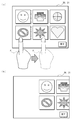
- a screen example 502 in FIG. 3B shows a screen that is displayed as a progress of the movement of the object group 600 while the display coordinates of the object group 600 are changed stepwise.
- the difference from the point P3 to the point P1 is the same value as the movement distance.
- the control unit 10 may draw an object that does not move by a gesture, a background image, or the like, like the button 700 in FIG.
- Step S103 the control unit 10 performs an elapsed time calculation process as the elapsed time calculation unit 100.
- the control unit 10 returns to the execution state.
- the control unit 10 obtains the current time from the timer unit 18 and subtracts the start time 210 to calculate the elapsed time 220.
- the elapsed time 220 is a time elapsed from the start of the movement of the object.
- the control unit 10 stores the calculated elapsed time 220 in the storage unit 19.
- Step S104 the control unit 10 performs a movement interval value calculation process as the movement interval value calculation unit 110.
- the control unit 10 divides the elapsed time 220 by the travel time 200 to calculate a ratio value. Then, the control unit 10 calculates a value of the movement interval obtained by multiplying the ratio and the movement distance as the movement interval value 250.
- the control unit 10 stores the calculated movement interval value 250 in the storage unit 19.
- Step S105 the control unit 10 performs a display coordinate setting process as the standby unit 120 after setting the movement interval value.
- the control unit 10 sets a value obtained by adding a moving distance to the display coordinates of the object data 300.
- a point P2 in the middle of movement with the movement interval value 250 added is shown.
- Step S106 the control unit 10 performs a standby state transition process as the standby unit 120 after setting the movement interval value.
- the control unit 10 puts a thread or the like into a standby state such as sleep.
- Step S107 the control unit 10 performs an object drawing process as the object drawing unit 130.
- the control unit 10 draws the image data 310 on the coordinates reflecting the display coordinates for each object data 300 using a browser or the like, and displays the image data 310 on the display unit 21.
- Step S108 the control unit 10 determines whether or not the movement of the object is completed as the object drawing unit 130.
- the control unit 10 determines Yes when the movement of the object is completed. In other cases, the control unit 10 determines No. In the case of Yes, the control part 10 complete
- the object movement process according to the embodiment of the present invention is completed.
- the image forming apparatus 1 changes the display coordinates 320 of the object data 300 in a stepwise manner from the start coordinates 230 to the end coordinates 240 within the movement time 200, while changing the object data.
- 300 is an information processing apparatus that displays 300 image data 310 on the display unit 21, an elapsed time calculation unit 100 that calculates an elapsed time 220 from the start of the movement of the object, and an elapsed time 220 that is calculated by the elapsed time calculation unit 100.
- the movement interval value calculation unit 110 calculates the movement interval value 250 of the display coordinates 320 of the object, and the movement interval calculation unit from the ratio between the movement time 200 and the difference between the end coordinate 240 and the start coordinate 230.
- the movement interval value 250 is added to the display coordinates 320 of the object, and the movement is performed in a standby state for a predetermined standby time
- the waiting unit 120 after setting the threshold value and the object drawing unit 130 that draws the object at the coordinates to which the moving interval value 250 is added and displays it on the display unit while the standby unit 120 is set to the waiting state after the setting of the moving interval value. It is characterized by providing.
- the image forming apparatus 1 calculates the display coordinates 320 on which the object is drawn from the movement time 200 where the drawing specified in advance is to be completed. For this reason, even if the number of times of drawing, timing, and the like change, the coordinates of the end position of the movement of the object can be calculated in the scheduled movement time 200.
- the completion time of the movement of the object is constant regardless of the state of the control unit 10, and the control calculation capability of the control unit 10 can be used effectively.
- the movement interval value 250 is dynamically calculated, so that an appropriate number of movements and intervals can be ensured. For this reason, it is possible to stabilize the time until the movement of the object is completed and improve the operability of the user.
- the image forming apparatus 1 includes an input unit that acquires an instruction by a user's gesture, and the object is various instruction images displayed on a browser, and the positions of various current instruction images Is set as the start coordinate 230, the coordinate of the position indicated by the gesture acquired by the input unit is set as the end coordinate 240, and the time from the start to the end of the input of the gesture is set as the movement time 200. Is displayed by scrolling.
- the object can be smoothly scrolled and moved according to the processing capability of the control unit 10 using the coordinates indicated to the user by a gesture such as swipe.
- a gesture such as swipe.
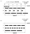
- FIG. 4A shows a conventional scroll process in which the scroll time is set to 500 milliseconds, the drawing interval time is set to 50 milliseconds, and the fixed value moving interval is set to 50 px (pixels).
- An example is shown. In this example, the image or the like is scrolled by 500 px in 500 milliseconds.
- A shows an example in which an appropriate drawing interval is designated.
- White squares indicate the processing of steps S204 to S206 described above, and black bars indicate the processing time of step S207 described above.
- drawing is performed at an appropriate interval.
- B shows an example in which the drawing time of the image drawing process is shortened due to the efficiency of firmware in the same model. Even in such a case, similarly to A, the drawing is performed only 10 times. However, the drawing interval corresponding to the scroll time becomes long, and a wasteful waiting time occurs.
- C shows an example in which background processing occurs and the drawing time becomes longer. In this case, the drawing process is not completed at the scheduled drawing interval time, and the scroll end time is delayed. The actual drawing time may become longer depending on the state of the control unit, and there is a problem that the time for completing the scrolling is long and becomes irregular. However, if the drawing interval time is increased in consideration of such background processing, the number of times of drawing per unit time decreases, causing a problem that the scrolling appears to flicker.
- FIG. 4B shows an example of the object drawing process of this embodiment.
- D to F show examples in which an appropriate movement interval value 250 is calculated according to the load of each drawing process in the object drawing process of the present embodiment.
- the coordinates of the scroll end position are calculated at the scheduled time even if the number and timing of drawing changes. For this reason, in this embodiment, regardless of the state of the control unit 10, the time required for the drawing process, etc., the control unit 10 can be used efficiently and the drawing can be performed as smoothly as possible. Further, there is no delay until the drawing process is completed. Further, it is possible to calculate the optimum drawing interval on different hardware and without stopping the background processing. In addition, screen drawing suitable for the specifications of the model can be performed.
- the movement interval value 250 is calculated every time. However, even if the drawing is performed once, the time required for the drawing is calculated to calculate the movement interval value 250, and thereafter, the interval timer is set and the calculated movement interval value 250 is added. Good. With this configuration, it is not necessary to calculate a ratio or the like, so that the processing load can be reduced.
- drawing processing is performed after entering a standby state on a browser having different performance.
- it may be configured to draw by vertical synchronization or the like regardless of the drawing interval of the browser.
- the object to be moved is various instruction images.
- the object to be moved may include an object to be dragged on the screen, a background image, and the like.
- different instruction interval images, background images, and the like may be set with different movement interval values 250 and rendered as a so-called “double scroll”.
- the XY coordinates in the three-dimensional space may be moved, and affine transformation or the like may be performed and projected into the two-dimensional space for drawing.
- the present invention can also be applied to an information processing apparatus other than the image forming apparatus. That is, a configuration using a network scanner, a server in which the scanner is separately connected by a USB, or the like may be used.
- the processing by the image forming apparatus 1 is described.
- the object movement processing of the present embodiment can also be applied to application software on an OS such as a WWW browser such as a PC or a smartphone or Windows (registered trademark).
Landscapes
- Engineering & Computer Science (AREA)
- General Engineering & Computer Science (AREA)
- Theoretical Computer Science (AREA)
- Human Computer Interaction (AREA)
- Physics & Mathematics (AREA)
- General Physics & Mathematics (AREA)
- Multimedia (AREA)
- Signal Processing (AREA)
- User Interface Of Digital Computer (AREA)
- Facsimiles In General (AREA)
Abstract
Description
このような画像形成装置では、ユーザーの指示により、表示部に表示された画像を縦横へ移動させる「スクロール」処理を行うことができるものが存在する。
このような従来のスクロール処理の例が、特許文献1に記載されている。
従来のジェスチャーによるスクロール処理では、アプリケーションの描画部は、なぞられた方向に、画像の座標を段階的に移動させて描画する。この処理を連続で繰り返すことで、画面のスクロールを実現させる。
以下、図8のフローチャートにより具体的な処理のステップについて説明する。
まず、固定値初期値設定処理では、記憶部に記憶された画像形成装置の機種コードが取得される。また、この機種コードにより、機種コードと描画間隔時間のペアが格納された描画間隔時間テーブルを参照し、描画間隔時間が設定される。これにより、当該画像形成装置に適した描画間隔時間を取得させることができる。
この描画間隔時間の適切な値は、画像形成装置のハードウェアのスペック(性能)によって、異なっている。たとえば、描画間隔時間として、表示部21のリフレッシュレートと同期する値を設定してもよい。リフレッシュレート60Hzであれば、理想的な描画間隔時間は、1/60*1000=16.7m秒となる。実際には、画像形成装置の表示部21は、PC(Personal Computer)よりもスペックが低いため、16.7mSec間隔で描画できるケースは稀となる。
次に、ジェスチャー取得処理では、ユーザーがタッチパネルをなぞったとき、ジェスチャー操作がされたこと、及び、なぞられた方向が検知される。
また、スクロール時間として設定された時間の値を記憶部から取得し、これを描画間隔時間で割って、描画回数の値が算出される。
また、なぞられた方向にスクロールさせる距離を記憶部から取得し、算出された描画回数の値で割ることで、画像の座標を段階的に移動させる移動間隔の値が算出される。
次に、インターバルタイマー設定処理では、設定された描画間隔時間で描画を行うように、画像の表示座標を設定する処理を呼び出すインターバルタイマーが設定される。
次に、タイマー時刻待ち処理では、画像の表示座標を設定するスレッド等が、インターバルタイマーにより呼び出されるまで待機(スリープ)の状態にされる。
次に、表示座標固定値加算処理では、画像の表示座標が移動される。設定された描画時間間隔が経過した場合、インターバルタイマーにより、画像の表示座標を設定するスレッド等が実行状態にされる。その後、このスレッドにより、各画像の座標を変更し、画像が表示される位置が変更される。
待機状態遷移処理では、各画像の座標を変更された後、画像の表示座標を設定するスレッド等が待機状態となり、処理がOS(Operating System)のブラウザー等に戻される。これは、画像の座標を設定する処理と、ブラウザー等がその座標に実際に描画をする処理とが、非同期で実行されるためである。
画像描画処理では、ブラウザー等により、座標が変更された画像が実際に描画される。これにより、実際の画像の見た目の位置が変更させる。
画像の描画が終了した後、設定された描画回数に到達したか否かが判断される。
Yesの場合、スクロール処理を終了させる。
Noの場合、ステップS204に処理を戻して、インターバルタイマーによる描画が続けられる。
本発明の情報処理方法は、所定の移動時間以内に、オブジェクトの表示座標を開始座標から終了座標まで段階的に変化させて移動させつつ、表示部に表示させる情報処理装置により実行される情報処理方法において、前記オブジェクトの移動の開始からの経過時間を算出し、算出された経過時間と前記移動時間との割合、及び前記終了座標と前記開始座標との差分から、前記オブジェクトの表示座標の移動間隔値を算出し、算出された移動間隔値を前記オブジェクトの表示座標に加え、前記オブジェクトの表示座標に前記移動間隔値が加えられた座標に、前記オブジェクトを描画して前記表示部に表示することを特徴とする。
〔画像形成装置1の全体の構成〕
まず、図5を参照して、画像形成装置1(情報処理装置)の全体の構成について説明する。
各部は、制御部10によって動作制御される。
制御部10は、記憶部19のROMやHDDに記憶されている制御プログラムを読み出して、この制御プログラムをRAMに展開させて実行することで、後述する機能ブロックの各部として動作させられる。また、制御部10は、図示しない外部の端末や操作パネル部16から入力された所定の指示情報に応じて、装置全体の制御を行う。
画像処理部11は、原稿読取部12で読み取られた画像を、記憶部19に印刷データとして記憶する。この際、画像処理部11は、印刷データをPDFやTIFF等のフォーマットのファイル単位に変換することも可能である。
原稿給送部13は、原稿読取部12で読み取られる原稿を搬送する。
画像形成部17は、ユーザーの出力指示により、記憶部19に記憶され、原稿読取部12で読み取られ、又は外部の端末から取得されたデータから記録紙への画像形成を行わせる。
搬送部は、給紙カセット42a(図6)から記録紙を搬送し、画像形成部17で画像形成させ、その後にスタックトレイ50へ搬送する。
なお、原稿読取部12、原稿給送部13、搬送部、画像形成部17の動作については後述する。
ネットワーク送受信部15は、データ通信用の回線ではデータを送受信し、音声電話回線では音声信号を送受信する。
入力部20は、ユーザーの指等の移動による指示であるジェスチャー(gesture)による指示を取得することが可能である。
表示部21は、ユーザーに知覚可能なアイコン(icon)や背景画像等のひとまとまりの単位の各種指示画像等である「オブジェクト(object)」を表示する。
また、表示部21は、記憶部19(図2参照)に記憶された、スキャン画像の「プレビュー」(preview)の画像等も表示可能である。
また、タイマー部18は、設定された時間の経過後に、スレッド等に例外を発生させたり、割り込み等を発生させるタイマーを設定可能である。タイマー部18は、このタイマーに設定された時間が経過した場合、待機状態となったスレッド等を実行状態に変更させる。
記憶部19のRAMは、省電力状態であっても、セルフリフレッシュ等の機能により、記憶内容が保持される。
記憶部19のROMやHDDには画像形成装置1の動作制御を行うための制御プログラムが記憶されている。これに加えて、記憶部19は、ユーザーのアカウント設定も記憶している。また、記憶部19には、ユーザー毎の保存フォルダーの領域が含まれていてもよい。
また、制御部10及び画像処理部11は、RAMやROMやフラッシュメモリー等を内蔵していてもよい。
また、画像形成装置1は、ファクシミリの送受信を行うFAX送受信部を備えていてもよい。
次に、図6を参照して、本発明の実施の形態に係る画像形成装置1の動作について説明する。
原稿読取部12は、本体部14の上部に配設され、原稿給送部13は、原稿読取部12の上部に配設されている。スタックトレイ50は、本体部14に形成された記録紙の排出口41側に配設され、また、操作パネル部16は、画像形成装置1のフロント側に配設されている。
プラテンガラス12bは、ガラス等の透明部材により構成された原稿台である。原稿読取スリット12cは、原稿給送部13による原稿の搬送方向と直交方向に形成されたスリットを有する。
また、原稿給送部13により搬送された原稿を読み取る場合には、スキャナー12aは、原稿読取スリット12cと対向する位置に移動され、原稿読取スリット12cを介し、原稿給送部13による原稿の搬送動作と同期して原稿を読み取って画像データ310を取得し、取得した画像データ310を本体部14に備わる制御部10に出力する。
なお、原稿給送部13は、可倒式に構成され、原稿給送部13を上方に持ち上げることで、プラテンガラス12bの上面を開放させることができる。
給紙ローラー42bによって用紙搬送路43に繰り出された記録紙は、搬送ローラー対44によって画像形成部17に搬送される。そして、画像形成部17によって記録が施された記録紙は、排出ローラー対45によってスタックトレイ50に排出される。
次に、図1により、画像形成装置1のシステム構成について説明する。
制御部10は、経過時間算出部100、移動間隔値算出部110、移動間隔値設定後待機部120(移動間隔値設定部)、及びオブジェクト描画部130を備えている。
記憶部19は、移動時間200、開始時刻210、経過時間220、開始座標230、終了座標240、移動間隔値250、及びオブジェクトデータ300を記憶している。
また、経過時間算出部100は、待機状態から実行状態となる度に、記憶部19と、タイマー部18で取得した現在時刻とを減算して、経過時間220を算出して記憶部19に保存する。
移動間隔値算出部110は、例えば、入力部20から取得されたジェスチャーから算出された終了座標240と開始座標230との差分である移動距離を用いて、以下の式(1)で移動間隔値250を算出する。
移動間隔値250 = 経過時間220 / 移動時間200 × 移動距離
…… 式(1)
なお、移動距離は、縦軸及び横軸方向の座標値を含むベクトル形式であってもよい。この場合、縦軸及び横軸方向のそれぞれにおいて、移動間隔値250を算出する。
なお、オブジェクト描画部130は、OS上で、HTMLとJava(登録商標)Script等のデータにより各種描画を行うブラウザーの機能として実装されていてもよい。
なお、待機時間は、最小の描画間隔を示す定数として、0~数マイクロ秒等の値を設定してもよい。この場合には、オブジェクト描画部130による描画が完了すると、すぐにスレッド等が待機状態から実行状態になる。
オブジェクトデータ300は、画像データ310と表示座標とを含んでいる。
画像データ310は、ブラウザー等により表示部21に表示される画像のデータであり、各種指示に係るアイコン等やプレビュー画像等が設定されていてもよい。
表示座標320は、画像データ310が表示される座標のデータである。表示座標320は、オブジェクトの移動に従い、段階的に移動間隔値250が追加される。
なお、開始座標230、終了座標240、表示座標として、表示部21のスクリーン座標を用いることが好適である。また、縦横で0~1の小数点を用いる座標、三次元空間上の座標、変換された座標、極座標系の座標等を用いることも可能である。
また、オブジェクトデータ300は、ID(Identification)、イベント時に呼び出される関数等が指定されていてもよい。また、オブジェクトデータ300には、グループ化や継承の情報、コンストラクターやデストラクター等の設定が含まれていてもよい。
また、上述の画像形成装置1の各部は、本発明の画像形成方法を実行するハードウェア資源となる。
次に、図2~図4を参照して、本発明の実施の形態に係る画像形成装置1によるオブジェクト移動処理の説明を行う。
本実施形態のオブジェクト描画処理では、オブジェクトの表示座標320を開始座標230から終了座標240まで所定の移動時間200以内に段階的に変化させつつ表示部に表示させる。この際に、オブジェクトの座標を段階的に変化させるための移動間隔値250を、経過時間220と移動時間200との割合、及び終了座標240と前記開始座標230との差分から算出する。
本実施形態のオブジェクト移動処理は、主に制御部10が、記憶部19に記憶されたプログラムを、各部と協働し、ハードウェア資源を用いて実行する。
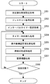
以下で、図2のフローチャートを参照して、オブジェクト移動処理の詳細をステップ毎に説明する。
まず、制御部10が、経過時間算出部100として、ジェスチャー取得処理を行う。
制御部10は、入力部20のタッチパネル等から、ユーザーのジェスチャーによる指示を取得する。たとえば、制御部10は、ユーザーがタッチパネルに指を接触させ、接触させたまま移動させるスワイプを行った場合、これをジェスチャーとして取得する。
次に、制御部10が、経過時間算出部100として、変動初期値設定処理を行う。
制御部10は、例えば、スワイプの場合、ユーザーの指の接触を検出した座標と、指が離れたことを検出した座標とから縦軸と横軸のベクトルを算出し、このベクトルから移動距離を算出する。制御部10は、ジェスチャーによる指示として、縦横のスクロールのみ行う場合は、縦軸又は横軸方向の移動距離を算出する。制御部10は、オブジェクトデータ300の現在の表示座標を開始座標230に設定し、記憶部19に保存する。また、制御部10は、この表示座標に、上述のベクトルを加えた座標を、終了座標240と設定して、記憶部19に保存する。
また、制御部10は、例えば、スワイプの場合、指が接触して離れるまでの時間を移動時間200として算出し、記憶部19に保存する。また、制御部10は、タイマー部18から現在時刻を取得し、開始時刻210として記憶部19に保存する。また、制御部10は、経過時間220に「0」を設定して、記憶部19に保存する。
なお、制御部10は、図3のボタン700のように、ジェスチャーにより移動しないオブジェクトや背景画像等を描画してもよい。
ここで、制御部10が、経過時間算出部100として、経過時間算出処理を行う。
制御部10は、オブジェクトデータ300の描画を行うスレッド等が待機状態であった場合、実行状態に戻す。
制御部10は、タイマー部18から現在時刻を取得して、開始時刻210を減算して、経過時間220を算出する。この経過時間220は、オブジェクトの移動の開始から経過した時間である。
制御部10は、算出した経過時間220を記憶部19に保存する。
次に、制御部10が、移動間隔値算出部110として、移動間隔値算出処理を行う。
制御部10は、経過時間220を移動時間200で割算して割合の値を算出する。この上で、制御部10は、この割合と移動距離とを掛け合わせた移動間隔の値を、移動間隔値250として算出する。制御部10は、算出された移動間隔値250を記憶部19に保存する。
次に、制御部10が、移動間隔値設定後待機部120として、表示座標設定処理を行う。
制御部10は、オブジェクトデータ300の表示座標に移動距離を付加した値を設定する。
図3(b)の画面例502では、移動間隔値250を付加された、移動途中の点P2が示されている。
次に、制御部10が、移動間隔値設定後待機部120として、待機状態遷移処理を行う。
制御部10は、スレッド等をスリープ等の待機状態にする。
次に、制御部10が、オブジェクト描画部130として、オブジェクト描画処理を行う。
制御部10は、ブラウザー等により、各オブジェクトデータ300について、表示座標を反映させた座標に、画像データ310を描画して表示部21に表示させる。
次に、制御部10が、オブジェクト描画部130として、オブジェクトの移動が完了したか否かを判定する。制御部10は、オブジェクトの移動が完了した場合に、Yesと判定する。制御部10は、それ以外の場合には、Noと判定する。
Yesの場合、制御部10は、オブジェクト移動処理を終了する。
Noの場合、制御部10は、処理をステップS103に戻して、待機状態から実行状態への復帰を待ってオブジェクトの移動を続ける。
以上により、本発明の実施の形態に係るオブジェクト移動処理を終了する。
従来は、新機種が開発されたときに、固定値の描画間隔時間のテーブルを作成し直す必要があった。
これに対して、本発明の実施の形態に係る画像形成装置1は、移動時間200以内に、オブジェクトデータ300の表示座標320を開始座標230から終了座標240まで段階的に変化させつつ、オブジェクトデータ300の画像データ310を表示部21に表示させる情報処理装置であり、オブジェクトの移動の開始からの経過時間220を算出する経過時間算出部100と、経過時間算出部100により算出された経過時間220と移動時間200との割合、及び終了座標240と開始座標230との差分から、オブジェクトの表示座標320の移動間隔値250を算出する移動間隔値算出部110と、移動間隔算出部により算出された移動間隔値250をオブジェクトの表示座標320に加え、所定の待機時間、待機状態とする移動間隔値設定後待機部120と、移動間隔値設定後待機部120により待機状態となった間に、移動間隔値250が加えられた座標にオブジェクトを描画して表示部に表示させるオブジェクト描画部130とを備えることを特徴とする。
このように構成することで、画面を描画する位置である移動間隔値250をスクロール完了予定時間と、現在の時間から動的に算出できる。このため、そもそも、固定値の描画間隔時間のテーブルを作成する必要がなくなる。また、新機種でも、プログラムを変更することなく、新しい機種上で同様に動作させることができる。よって、開発コストを低減することができる。
これに対して、本実施形態の画像形成装置1は、オブジェクトの描画する表示座標320を、予め指定した描画が完了する予定の移動時間200から算出する。このため、描画の回数、タイミング等が変わっても、予定の移動時間200にはオブジェクトの移動の終了位置の座標を算出することができる。また、オブジェクトの移動の完了時間は、制御部10の状態に関係なく一定となり、制御部10の制御演算能力を有効に活用することができる。
これに対して、本実施形態では、バックグラウンドの処理があった場合でも、動的に移動間隔値250を算出するため、適切な移動回数や間隔を確保できる。このため、オブジェクトの移動が完了するまでの時間を安定化させ、ユーザーの操作性を向上させることが可能となる。
このように構成することで、スワイプ等のジェスチャーによりユーザーに示された座標を用いて、制御部10の処理能力に応じて、オブジェクトをスムーズにスクロールさせて移動させることが可能となる。これにより、処理能力や描画能力が低い画像形成装置の制御部10により実行されるブラウザー等を用いても、ユーザーの操作性高くスクロール描画を行うことができる。
図4(a)は、従来のスクロール処理で、スクロール時間が500m秒、描画間隔時間が50m秒、固定値の移動間隔が50px(ピクセル)に設定されており、描画回数10回だけ描画される例について示す。この例では、画像等を500m秒で500px、スクロールさせる。
Aは、適切な描画間隔が指定されている例を示す。白い四角は、上述のステップS204~S206の処理を示し、黒いバーは上述のステップS207の処理の時間を示す。このように、適切な描画間隔時間を指定した場合には、適切な間隔で描画される。
Bは、同一機種において、ファームウェアの効率化等で画像描画処理の描画時間が短くなった例を示す。このような場合でも、Aと同様に、10回だけ描画される。しかしながら、スクロール時間に対応する描画間隔が長くなり、無駄な待ち時間が発生する。
Cは、バックグラウンドの処理が発生して描画時間が長くなった例を示す。この場合、予定の描画間隔時間では描画処理が完了せず、スクロール終了の時刻が遅延していた。実際に描画する時間は、制御部の状態により長くなる場合があり、スクロールが完了する時間が長く、不規則になる問題もあった。しかしながら、このようなバックグラウンドの処理まで考慮して描画間隔時間を長くすると、単位時間当たりの描画回数が少なくなり、スクロールがちらついて見えるようになるという問題が生じる。
D~Fは、本実施形態のオブジェクト描画処理において、それぞれの描画処理の負荷に応じて、適切な移動間隔値250が算出された例を示す。
本実施形態では、描画の回数、タイミングが変わっても、予定の時間にはスクロール終了位置の座標が算出される。このため、本実施形態では、制御部10の状態、描画処理にかかる時間等に関係なく制御部10を効率的に利用し、可能な限り多くスムーズに描画できる。また、描画処理の完了までの遅れも発生しない。また、異なるハードウェア上で、且つバックグラウンドの処理を停止させることなく、最適な描画間隔を算出することができる。また、機種のスペックに適した画面描画を行うことができる。
しかしながら、一度描画させてからその描画に必要な時間を算出して移動間隔値250を算出し、その後はインターバルタイマーを設定し、算出された移動間隔値250を加算するような処理であってもよい。
このように構成することで、割合等を算出する必要がなくなるため、処理負担を軽減することができる。
また、本発明の実施の形態において、移動させるオブジェクトについては、各種指示画像等である例について記載した。しかしながら、移動させるオブジェクトには、画面上でドラッグするオブジェクトや背景画像等も含めてもよい。この場合、各種指示画像等と背景画像等とは、異なる移動間隔値250を設定し、いわゆる『二重スクロール』のような描画を行ってもよい。また、表示部21のスクリーン座標を移動させるのではなく、三次元空間のXY座標を移動させて、アフィン変換等をして二次元空間に投影して描画してもよい。
また、本発明の実施の形態においては、画像形成装置1による処理について記載した。しかしながら、本実施形態のオブジェクト移動処理は、PCやスマートフォン等のWWWブラウザー、Windows(登録商標)等のOS上のアプリケーション・ソフトウェア等においても適用可能である。
10 制御部
11 画像処理部
12 原稿読取部
12a スキャナー
12b プラテンガラス
12c 原稿読取スリット
13 原稿給送部
13a 原稿載置部
13b 原稿排出部
13c 原稿搬送機構
14 本体部
15 ネットワーク送受信部
16 操作パネル部
17 画像形成部
17a 感光体ドラム
17b 露光部
17c 現像部
17d 転写部
17e 定着部
18 タイマー部
19 記憶部
20 入力部
21 表示部
41 排出口
42 給紙部
42a 給紙カセット
42b 給紙ローラー
43 用紙搬送路
44 搬送ローラー対
45 排出ローラー対
50 スタックトレイ
100 経過時間算出部
110 移動間隔値算出部
120 移動間隔値設定後待機部
130 オブジェクト描画部
200 移動時間
210 開始時刻
220 経過時間
230 開始座標
240 終了座標
250 移動間隔値
300 オブジェクトデータ
310 画像データ
320 表示座標
501、502、503 画面例
600 オブジェクト群
700 ボタン
P1、P2、P3 点
Claims (4)
- 所定の移動時間以内に、オブジェクトの表示座標を開始座標から終了座標まで段階的に変化させて移動させつつ、表示部に表示させる情報処理装置において、
前記オブジェクトの移動の開始からの経過時間を算出する経過時間算出部と、
該経過時間算出部により算出された経過時間と前記移動時間との割合、及び前記終了座標と前記開始座標との差分から、前記オブジェクトの表示座標の移動間隔値を算出する移動間隔値算出部と、
該移動間隔算出部により算出された移動間隔値を前記オブジェクトの表示座標に加える移動間隔値設定部と、
該移動間隔値設定部により前記オブジェクトの表示座標に前記移動間隔値が加えられた座標に、前記オブジェクトを描画して前記表示部に表示させるオブジェクト描画部とを備える
ことを特徴とする情報処理装置。 - ユーザーのジェスチャーによる指示を取得する入力部を備え、
前記オブジェクトは、ブラウザーに表示される各種指示画像であり、
現在の前記各種指示画像の位置の座標を前記開始座標とし、前記入力部により取得されたジェスチャーで示された位置の座標を前記終了座標とし、前記ジェスチャーの入力の開始から終了までの時間を前記移動時間とすることで、前記各種指示画像をスクロールさせて表示する
ことを特徴とする請求項1に記載の情報処理装置。 - 所定の移動時間以内に、オブジェクトの表示座標を開始座標から終了座標まで段階的に変化させて移動させつつ、操作パネルの表示部に表示させる画像形成装置において、
前記オブジェクトの移動の開始からの経過時間を算出する経過時間算出部と、
該経過時間算出部により算出された経過時間と前記移動時間との割合、及び前記終了座標と前記開始座標との差分から、前記オブジェクトの表示座標の移動間隔値を算出する移動間隔値算出部と、
該移動間隔算出部により算出された移動間隔値を前記オブジェクトの表示座標に加える移動間隔値設定部と、
該移動間隔値設定部により前記オブジェクトの表示座標に前記移動間隔値が加えられた座標に、前記オブジェクトを描画して前記表示部に表示させるオブジェクト描画部とを備える
ことを特徴とする画像形成装置。 - 所定の移動時間以内に、オブジェクトの表示座標を開始座標から終了座標まで段階的に変化させて移動させつつ、表示部に表示させる情報処理装置により実行される情報処理方法において、
前記オブジェクトの移動の開始からの経過時間を算出し、
算出された経過時間と前記移動時間との割合、及び前記終了座標と前記開始座標との差分から、前記オブジェクトの表示座標の移動間隔値を算出し、
算出された移動間隔値を前記オブジェクトの表示座標に加え、
前記オブジェクトの表示座標に前記移動間隔値が加えられた座標に、前記オブジェクトを描画して前記表示部に表示する
ことを特徴とする情報処理方法。
Priority Applications (2)
| Application Number | Priority Date | Filing Date | Title |
|---|---|---|---|
| US15/100,312 US10091367B2 (en) | 2013-11-29 | 2014-09-19 | Information processing device, image forming apparatus and information processing method |
| JP2015550597A JP6121564B2 (ja) | 2013-11-29 | 2014-09-19 | 情報処理装置、画像形成装置、及び情報処理方法 |
Applications Claiming Priority (2)
| Application Number | Priority Date | Filing Date | Title |
|---|---|---|---|
| JP2013-247960 | 2013-11-29 | ||
| JP2013247960 | 2013-11-29 |
Publications (1)
| Publication Number | Publication Date |
|---|---|
| WO2015079784A1 true WO2015079784A1 (ja) | 2015-06-04 |
Family
ID=53198738
Family Applications (1)
| Application Number | Title | Priority Date | Filing Date |
|---|---|---|---|
| PCT/JP2014/074771 Ceased WO2015079784A1 (ja) | 2013-11-29 | 2014-09-19 | 情報処理装置、画像形成装置、及び情報処理方法 |
Country Status (3)
| Country | Link |
|---|---|
| US (1) | US10091367B2 (ja) |
| JP (1) | JP6121564B2 (ja) |
| WO (1) | WO2015079784A1 (ja) |
Families Citing this family (5)
| Publication number | Priority date | Publication date | Assignee | Title |
|---|---|---|---|---|
| US10551945B2 (en) * | 2017-03-02 | 2020-02-04 | Texas Instruments Incorporated | Touch slider-position sensing |
| USD850469S1 (en) * | 2018-01-05 | 2019-06-04 | Google Llc | Display screen or portion thereof with transitional graphical user interface |
| USD845985S1 (en) * | 2018-01-05 | 2019-04-16 | Google Llc | Display screen or portion thereof with transitional graphical user interface |
| USD845330S1 (en) * | 2018-01-05 | 2019-04-09 | Google Llc | Display screen or portion thereof with transitional graphical user interface |
| US11842729B1 (en) | 2019-05-08 | 2023-12-12 | Apple Inc. | Method and device for presenting a CGR environment based on audio data and lyric data |
Citations (3)
| Publication number | Priority date | Publication date | Assignee | Title |
|---|---|---|---|---|
| JPH0764706A (ja) * | 1993-08-30 | 1995-03-10 | Mitsubishi Electric Corp | データ再生装置 |
| JP2005531824A (ja) * | 2001-10-30 | 2005-10-20 | ヒューレット・パッカード・カンパニー | 3次元グラフィック環境と対話する方法 |
| WO2012008099A1 (ja) * | 2010-07-12 | 2012-01-19 | パナソニック株式会社 | 設計支援装置、設計支援プログラム、設計支援方法、及び集積回路 |
Family Cites Families (9)
| Publication number | Priority date | Publication date | Assignee | Title |
|---|---|---|---|---|
| JP3381903B2 (ja) | 1998-05-21 | 2003-03-04 | 国際航業株式会社 | 地図表示システム及びそれにおける画像スクロール処理方法 |
| JP4752921B2 (ja) * | 2009-01-28 | 2011-08-17 | ソニー株式会社 | 情報処理装置、アニメーション付加方法、及びプログラム |
| JP2010176332A (ja) * | 2009-01-28 | 2010-08-12 | Sony Corp | 情報処理装置、情報処理方法およびプログラム |
| JP5506375B2 (ja) * | 2009-12-25 | 2014-05-28 | キヤノン株式会社 | 情報処理装置及びその制御方法 |
| JP5810812B2 (ja) * | 2011-10-06 | 2015-11-11 | コニカミノルタ株式会社 | 画像処理装置、画像処理装置の制御方法、および制御プログラム |
| JP2013105461A (ja) * | 2011-11-16 | 2013-05-30 | Canon Inc | 情報処理装置及びその制御方法 |
| JP5979916B2 (ja) * | 2012-03-07 | 2016-08-31 | キヤノン株式会社 | 情報処理装置およびその制御方法 |
| JP6012437B2 (ja) * | 2012-11-29 | 2016-10-25 | シナプティクス・ジャパン合同会社 | 半導体装置及び電子機器 |
| JP5772802B2 (ja) * | 2012-11-29 | 2015-09-02 | コニカミノルタ株式会社 | 情報処理装置、情報処理装置の制御方法、及び情報処理装置の制御プログラム |
-
2014
- 2014-09-19 JP JP2015550597A patent/JP6121564B2/ja active Active
- 2014-09-19 US US15/100,312 patent/US10091367B2/en active Active
- 2014-09-19 WO PCT/JP2014/074771 patent/WO2015079784A1/ja not_active Ceased
Patent Citations (3)
| Publication number | Priority date | Publication date | Assignee | Title |
|---|---|---|---|---|
| JPH0764706A (ja) * | 1993-08-30 | 1995-03-10 | Mitsubishi Electric Corp | データ再生装置 |
| JP2005531824A (ja) * | 2001-10-30 | 2005-10-20 | ヒューレット・パッカード・カンパニー | 3次元グラフィック環境と対話する方法 |
| WO2012008099A1 (ja) * | 2010-07-12 | 2012-01-19 | パナソニック株式会社 | 設計支援装置、設計支援プログラム、設計支援方法、及び集積回路 |
Also Published As
| Publication number | Publication date |
|---|---|
| JPWO2015079784A1 (ja) | 2017-03-16 |
| JP6121564B2 (ja) | 2017-04-26 |
| US20160301817A1 (en) | 2016-10-13 |
| US10091367B2 (en) | 2018-10-02 |
Similar Documents
| Publication | Publication Date | Title |
|---|---|---|
| US11276144B2 (en) | Information processing apparatus, display control method, and storage medium | |
| US20140145991A1 (en) | Information processing apparatus installed with touch panel as user interface | |
| JP6121564B2 (ja) | 情報処理装置、画像形成装置、及び情報処理方法 | |
| JP6330349B2 (ja) | 表示制御装置、表示システム、操作表示装置、プログラム | |
| US9001368B2 (en) | Image processing apparatus, operation standardization method, and non-transitory computer-readable recording medium encoded with operation standardization program with an application program that supports both a touch panel capable of detecting only one position and a touch panel capable of detecting a plurality of positions simultaneously | |
| US8970860B2 (en) | Image processing device that displays process sequence, display device and non-transitory computer readable recording medium | |
| JP2014219706A (ja) | 画像処理装置、携帯端末装置、リモート画面データの作成プログラム及び表示制御プログラム | |
| US20160165082A1 (en) | Function setting device and image forming apparatus | |
| JP2013228973A (ja) | 情報処理装置及び画像形成装置 | |
| KR20150139337A (ko) | 화상형성장치의 애플리케이션 실행을 조작하는 화면을 제공하는 방법 및 이를 이용하는 화상형성장치 | |
| US10152167B2 (en) | Operation display system, operation display device, and operation display program | |
| US9667831B2 (en) | Information processing apparatus, printing method, and non-transitory computer-readable recording medium for generating print data corresponding to a display image | |
| JP2018037997A (ja) | 画像形成装置 | |
| JP6092074B2 (ja) | 情報処理装置、画像形成システム、及び情報処理方法 | |
| KR102333135B1 (ko) | 화상형성장치의 애플리케이션 실행을 조작하는 화면을 제공하는 방법 및 이를 이용하는 화상형성장치 | |
| JP6079659B2 (ja) | 表示システム、画像形成装置、プログラム、表示状態制御方法 | |
| JP5472023B2 (ja) | 表示処理装置およびコンピュータプログラム | |
| KR20170063375A (ko) | 정보 처리 장치, 정보 처리 장치의 제어 방법 및 저장 매체 | |
| JPWO2020095876A1 (ja) | 画像形成装置、数値カウント方法 | |
| JP6176284B2 (ja) | 操作表示システム、操作表示装置および操作表示プログラム | |
| US20140040827A1 (en) | Information terminal having touch screens, control method therefor, and storage medium | |
| CN105323402B (zh) | 便携终端和印刷请求方法 | |
| JP5968926B2 (ja) | 情報処理装置及び情報処理プログラム | |
| JP6470485B2 (ja) | 画像処理装置、画像処理方法、及び、プログラム | |
| JP2018041469A (ja) | 画像処理装置、画像処理方法、及び、プログラム |
Legal Events
| Date | Code | Title | Description |
|---|---|---|---|
| 121 | Ep: the epo has been informed by wipo that ep was designated in this application |
Ref document number: 14865242 Country of ref document: EP Kind code of ref document: A1 |
|
| ENP | Entry into the national phase |
Ref document number: 2015550597 Country of ref document: JP Kind code of ref document: A |
|
| WWE | Wipo information: entry into national phase |
Ref document number: 15100312 Country of ref document: US |
|
| NENP | Non-entry into the national phase |
Ref country code: DE |
|
| 122 | Ep: pct application non-entry in european phase |
Ref document number: 14865242 Country of ref document: EP Kind code of ref document: A1 |