WO2015076281A1 - 発光装置、発光装置製造方法 - Google Patents
発光装置、発光装置製造方法 Download PDFInfo
- Publication number
- WO2015076281A1 WO2015076281A1 PCT/JP2014/080586 JP2014080586W WO2015076281A1 WO 2015076281 A1 WO2015076281 A1 WO 2015076281A1 JP 2014080586 W JP2014080586 W JP 2014080586W WO 2015076281 A1 WO2015076281 A1 WO 2015076281A1
- Authority
- WO
- WIPO (PCT)
- Prior art keywords
- type side
- electrode
- light emitting
- substrate electrode
- side substrate
- Prior art date
Links
Images


Classifications
-
- H—ELECTRICITY
- H01—ELECTRIC ELEMENTS
- H01L—SEMICONDUCTOR DEVICES NOT COVERED BY CLASS H10
- H01L33/00—Semiconductor devices with at least one potential-jump barrier or surface barrier specially adapted for light emission; Processes or apparatus specially adapted for the manufacture or treatment thereof or of parts thereof; Details thereof
- H01L33/48—Semiconductor devices with at least one potential-jump barrier or surface barrier specially adapted for light emission; Processes or apparatus specially adapted for the manufacture or treatment thereof or of parts thereof; Details thereof characterised by the semiconductor body packages
- H01L33/62—Arrangements for conducting electric current to or from the semiconductor body, e.g. lead-frames, wire-bonds or solder balls
-
- H—ELECTRICITY
- H01—ELECTRIC ELEMENTS
- H01L—SEMICONDUCTOR DEVICES NOT COVERED BY CLASS H10
- H01L2224/00—Indexing scheme for arrangements for connecting or disconnecting semiconductor or solid-state bodies and methods related thereto as covered by H01L24/00
- H01L2224/01—Means for bonding being attached to, or being formed on, the surface to be connected, e.g. chip-to-package, die-attach, "first-level" interconnects; Manufacturing methods related thereto
- H01L2224/10—Bump connectors; Manufacturing methods related thereto
- H01L2224/15—Structure, shape, material or disposition of the bump connectors after the connecting process
- H01L2224/16—Structure, shape, material or disposition of the bump connectors after the connecting process of an individual bump connector
- H01L2224/161—Disposition
- H01L2224/16151—Disposition the bump connector connecting between a semiconductor or solid-state body and an item not being a semiconductor or solid-state body, e.g. chip-to-substrate, chip-to-passive
- H01L2224/16221—Disposition the bump connector connecting between a semiconductor or solid-state body and an item not being a semiconductor or solid-state body, e.g. chip-to-substrate, chip-to-passive the body and the item being stacked
- H01L2224/16225—Disposition the bump connector connecting between a semiconductor or solid-state body and an item not being a semiconductor or solid-state body, e.g. chip-to-substrate, chip-to-passive the body and the item being stacked the item being non-metallic, e.g. insulating substrate with or without metallisation
-
- H—ELECTRICITY
- H01—ELECTRIC ELEMENTS
- H01L—SEMICONDUCTOR DEVICES NOT COVERED BY CLASS H10
- H01L2224/00—Indexing scheme for arrangements for connecting or disconnecting semiconductor or solid-state bodies and methods related thereto as covered by H01L24/00
- H01L2224/01—Means for bonding being attached to, or being formed on, the surface to be connected, e.g. chip-to-package, die-attach, "first-level" interconnects; Manufacturing methods related thereto
- H01L2224/26—Layer connectors, e.g. plate connectors, solder or adhesive layers; Manufacturing methods related thereto
- H01L2224/31—Structure, shape, material or disposition of the layer connectors after the connecting process
- H01L2224/32—Structure, shape, material or disposition of the layer connectors after the connecting process of an individual layer connector
- H01L2224/321—Disposition
- H01L2224/32151—Disposition the layer connector connecting between a semiconductor or solid-state body and an item not being a semiconductor or solid-state body, e.g. chip-to-substrate, chip-to-passive
- H01L2224/32221—Disposition the layer connector connecting between a semiconductor or solid-state body and an item not being a semiconductor or solid-state body, e.g. chip-to-substrate, chip-to-passive the body and the item being stacked
- H01L2224/32225—Disposition the layer connector connecting between a semiconductor or solid-state body and an item not being a semiconductor or solid-state body, e.g. chip-to-substrate, chip-to-passive the body and the item being stacked the item being non-metallic, e.g. insulating substrate with or without metallisation
-
- H—ELECTRICITY
- H01—ELECTRIC ELEMENTS
- H01L—SEMICONDUCTOR DEVICES NOT COVERED BY CLASS H10
- H01L2224/00—Indexing scheme for arrangements for connecting or disconnecting semiconductor or solid-state bodies and methods related thereto as covered by H01L24/00
- H01L2224/73—Means for bonding being of different types provided for in two or more of groups H01L2224/10, H01L2224/18, H01L2224/26, H01L2224/34, H01L2224/42, H01L2224/50, H01L2224/63, H01L2224/71
- H01L2224/732—Location after the connecting process
- H01L2224/73201—Location after the connecting process on the same surface
- H01L2224/73203—Bump and layer connectors
- H01L2224/73204—Bump and layer connectors the bump connector being embedded into the layer connector
-
- H—ELECTRICITY
- H01—ELECTRIC ELEMENTS
- H01L—SEMICONDUCTOR DEVICES NOT COVERED BY CLASS H10
- H01L2933/00—Details relating to devices covered by the group H01L33/00 but not provided for in its subgroups
- H01L2933/0008—Processes
- H01L2933/0033—Processes relating to semiconductor body packages
- H01L2933/0066—Processes relating to semiconductor body packages relating to arrangements for conducting electric current to or from the semiconductor body
Definitions
- the present invention relates to a light emitting device in which a light emitting element such as a light emitting diode (LED) chip is flip-chip mounted on a mounting substrate with an anisotropic conductive adhesive paste, and a method for manufacturing the same.
- a light emitting element such as a light emitting diode (LED) chip is flip-chip mounted on a mounting substrate with an anisotropic conductive adhesive paste, and a method for manufacturing the same.
- the LED chip is fixed to the substrate from the back side thereof with a photo-curable die bond agent, and the n-type side element electrode and the p-type side element electrode provided on the surface are connected to the n-type side electrode pattern and the p-type side electrode of the substrate.
- a photo-curable die bond agent Conventionally, light-emitting devices connected to patterns by a gold wire bonding method have been put into practical use.
- a light reflective electrode can be applied as an electrode formed between the light emitting layer and the p-type side element electrode, so that the light extraction efficiency is not reduced. can do.
- the light emitting layer near the surface of the LED chip can be brought close to the mounting substrate, the heat generated in the light emitting layer can be efficiently radiated to the substrate.
- FIG. 4A to 4D show such a prior art light emitting device 100.
- 4B is a cross-sectional view taken along the line AA in FIG. 4A
- FIG. 4C is a cross-sectional view taken along the line BB.
- an anisotropic conductive adhesive paste 160 is disposed between the light emitting element (LED chip) 400 and the mounting substrate 150, and the light emitting element 400 is pressed against the mounting substrate 150. Then, the anisotropic conductive adhesive paste 160 is extruded from between the light emitting element 400 and the mounting substrate 150 to shorten the distance between the light emitting element 400 and the mounting substrate 150.
- the conductive particles 161 contained in the anisotropic conductive adhesive paste 160 are sandwiched between the p-type side element electrode 111a and the p-type side substrate electrode 151a, and the n-type side element electrode 111b.
- the n-type substrate electrode 151b is electrically connected to each other by the conductive particles 161.
- the anisotropic conductive adhesive paste 160 is cured by heating or the like, the light emitting device 100 shown in FIGS. 4A to 4C is obtained.
- the technique for mechanically and electrically mounting the light emitting element 400 on the mounting substrate in this way is called flip chip mounting.
- the p-type side substrate electrode 151 a and the n-type side substrate electrode 151 b are electrically connected to the wirings 153 and 154 on the back side by connection plugs 155 and 156 that penetrate the mounting substrate 150, respectively.
- the provided power supply circuit 158 applies a voltage to the wirings 153 and 154, a voltage is applied between the p-type side element electrode 111 a and the n-type side element electrode 111 b, and a current flows in the pn junction inside the light emitting element 400. Then, the pn junction portion emits light.
- the emitted light generated by the light emission is directed to a surface of the light emitting element 400 that faces the mounting substrate 150, a surface opposite to the mounting substrate 150, and a side surface. Light emitted toward the surface opposite to the mounting substrate 150 is emitted to the outside of the light emitting device 100.
- the p-type side substrate electrode 151a and the n-type side substrate electrode 151b have a function of reflecting emitted light, and the p-type side substrate electrode 151a and the n-type side substrate electrode 151b are formed in a large area.
- the emitted light emitted from the surface facing the mounting substrate 150 is reflected when irradiated to the p-type side substrate electrode 151a or the n-type side substrate electrode 151b, travels backward and passes through the light emitting element 400, and the light emitting element Of the 400 surfaces, the light is emitted from the surface opposite to the mounting substrate 150. Therefore, light emitted from the bottom surface of the LED chip is reflected upward and emitted to the outside by the p-type side substrate electrode 151a and the n-type side substrate electrode 151b, so that the light extraction efficiency is improved.
- bumps may be formed on the n-type side element electrode 111b and the p-type side element electrode 111a.
- the LED chip is used for the purpose of reducing manufacturing costs. Often don't have bumps.
- the anisotropic conductive adhesive paste 160 is applied to the light emitting element 400 and the mounting substrate 150.
- the portion of the anisotropic conductive adhesive paste 160 that protrudes outside the outer periphery of the light emitting element 400 rises, and the light emitting element 400 is raised. It will be hardened in contact with the side surface. 4B and 4C show such a cured state.
- the conductive particles 161 contained in the anisotropic conductive adhesive paste 160 have a property of scattering or absorbing the light emitted from the LED chip, and are therefore pushed out from between the light emitting element 400 and the mounting substrate 150. If the anisotropic conductive adhesive paste 160 covers the side surface of the light emitting device 400, there is a problem that light is not emitted from the side surface of the light emitting device 400 and the light extraction efficiency is lowered. In particular, when a bumpless LED chip that does not use a bump having a spacer function is applied, this problem has become prominent because the gap between the light emitting element 400 and the mounting substrate 150 becomes narrower.
- An object of the present invention is to solve the problems of the prior art, in a light-emitting device in which a light-emitting element is flip-chip mounted on a conductive pattern formed on a substrate using an anisotropic conductive adhesive paste.
- a light-emitting element is flip-chip mounted on a conductive pattern formed on a substrate using an anisotropic conductive adhesive paste.
- the inventors of the present invention press the substrate and the light emitting element, and when the anisotropic conductive adhesive paste is extruded from between the substrate and the light emitting element, the anisotropic conductive adhesive paste is above the bottom surface of the light emitting element. Therefore, the extruded anisotropic conductive adhesive paste can be held in the outer region in the planar direction from the peripheral edge of the light emitting element.
- the conductor pattern was removed, and it was found that a low floor portion lower than the conductor pattern surface by the thickness of the conductor pattern and exposing the surface of the substrate body may be formed around the LED chip, and the present invention was completed. I let you.
- the present invention provides an element body, a light emitting element having a p-type side element electrode and an n-type side element electrode provided on the same surface of the element body, a substrate body, and the same surface of the substrate body.
- a mounting substrate having a p-type side substrate electrode and an n-type side substrate electrode, and a cured anisotropy disposed between the light emitting element and the mounting substrate and fixing the light emitting element to the mounting substrate.
- a conductive adhesive paste between the p-type side element electrode and the p-type side substrate electrode and between the n-type side element electrode and the n-type side substrate electrode.
- the conductive particles contained in the adhesive paste are electrically connected to each other, and a voltage is applied between the p-type side substrate electrode and the n-type side substrate electrode so that the light emitting element emits light.
- a light emitting device comprising a surface of the p-type side substrate electrode and the n-type side group The surface of the electrode is disposed at a place higher than the surface of the substrate body, and the p-type side substrate electrode and the n-type side substrate electrode are the p-type side element electrode and the n-type side of the same light emitting element. It is the light-emitting device arrange
- the surface of the substrate body on which the p-type side substrate electrode and the n-type side substrate electrode are provided is formed in an elongated shape having a width narrower than that of the p-type side substrate electrode, and one end of the p-type side substrate electrode A p-type side connection wiring connected to the mold-side substrate electrode, and an n-type side connection wiring having an elongated shape narrower than the n-type side substrate electrode and having one end connected to the n-type side substrate electrode.
- the light emitting device is provided.
- the present invention is the light emitting device, wherein the light emitting element is a light emitting diode chip.
- the p-type side element electrode, the n-type side element electrode, the p-type side substrate electrode, and the n-type side substrate electrode are conductive thin films
- the light emitting device includes the conductive particles in contact with both the p-type substrate electrode and the conductive particles in contact with both the n-type element electrode and the n-type substrate electrode.
- the present invention provides an element body, a light emitting element having a p-type side element electrode and an n-type side element electrode provided on the same surface of the element body, a substrate body, and the same surface of the substrate body.
- a mounting substrate having a p-type side substrate electrode and an n-type side substrate electrode, and a cured anisotropic conductive adhesive disposed between the light emitting element and the mounting substrate and fixing the light emitting element to the mounting substrate And the anisotropic conductive adhesive paste between the p-type side element electrode and the p-type side substrate electrode and between the n-type side element electrode and the n-type side substrate electrode.
- the light emitting device is configured to be electrically connected by the conductive particles contained in the light emitting element and to emit light when the voltage is applied between the p-type side substrate electrode and the n-type side substrate electrode.
- a method of manufacturing a light emitting device for manufacturing a p-side substrate electrode The surface and the surface of the n-type side substrate electrode are arranged at a location higher than the surface of the substrate body, and the size of the planar shape of the p-type side substrate electrode and the size of the planar shape of the n-type side substrate electrode And the positions of the p-type side substrate electrode and the n-type side substrate electrode, and the p-type side substrate electrode and the n-type side substrate electrode are connected to the p-type side device electrode and the n of the device body.
- the mold side element electrode is formed so as not to protrude outside the outer periphery of the surface on which the mold side element electrode is formed. Prevent the p-type side substrate electrode and the n-type side substrate electrode from protruding outside the position directly below the outer periphery of the surface on which the p-type side element electrode and the n-type side element electrode are formed. However, the light emitting element is pressed against the mounting substrate, and the light emitting element is From between the mounting substrate and the extruded anisotropic conductive adhesive paste, a light emitting device manufacturing method of curing the anisotropic conductive adhesive paste.
- the p-type side substrate electrode is connected to one end of an elongated p-type side connection wiring having a narrower width than the p-type side substrate electrode, and the n-type side substrate electrode is connected to the n-type side electrode.
- the anisotropic conductive adhesive paste is extruded from between the light emitting element and the mounting substrate in a state in which one end of an elongated n-type side connection wiring narrower than the side substrate electrode is connected. is there.
- the area around the p-type side substrate electrode and the area around the n-type side substrate electrode are more than the surface of the conductor pattern except for the portion where the p-type side connection wiring and the n-type side connection wiring are connected. It has a low low floor.
- the low floor portion is an area that can accommodate the extruded anisotropic conductive adhesive paste so that the anisotropic conductive adhesive paste extruded from the back surface of the light emitting element does not crawl up the side surface of the light emitting element. .
- the anisotropic conductive adhesive paste extruded from between the substrate and the light emitting element is accommodated on this low floor portion and does not crawl the side surface of the light emitting element, emitted light emitted from the side surface of the light emitting element. Is not shielded by the anisotropic conductive adhesive paste, and the decrease in light extraction efficiency is prevented, and as a result, the amount of light emitted from the light emitting device can be increased.
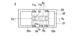
- the top view of the light-emitting device of the 1st example of this invention Sectional view taken along line A 1 -A 1 of the light emitting device of the first example Sectional view taken along line B 1 -B 1 of the light emitting device of the first example
- the top view of the mounting substrate for showing the conductor pattern of the light emitting device of the first example Sectional view taken along line C 1 -C 1 of the light emitting device of the first example Sectional drawing which shows the state which has arrange
- the top view of the mounting substrate for showing the conductor pattern of the light emitting device of the second example
- FIG. 1A is a light emitting device of the first example of the present invention
- FIG. 1B is a cross-sectional view taken along line A 1 -A 1 in FIG. 1A
- FIG. 1C is a cross-sectional view taken along line B 1 -B 1
- FIG. 1E is a cross-sectional view taken along line C 1 -C 1 .
- the light emitting device 1 of the first example includes a mounting substrate 20 and a light emitting element 10 mounted on the surface of the mounting substrate 20.
- the light emitting element 10 has an element body 14 formed of an LED (Light Emitting Diode) chip, and a p-type semiconductor region and an n-type semiconductor region are provided inside the element body 14.
- a p-type side element electrode 11a connected to the p-type semiconductor region and an n-type side element electrode 11b connected to the n-type semiconductor region are provided apart from each other. .
- the mounting substrate 20 has a substrate body 21, and a conductor pattern 30 formed by patterning a thin film of a conductor such as metal is provided on one surface of the substrate body 21. Only the surface of the conductor pattern 30 is higher than the surface of the substrate body 21.
- FIG. 1D is a plan view of the mounting substrate 20 for explaining the planar shape of the conductor pattern 30 of the mounting substrate 20.
- the conductor pattern 30 has a p-type side substrate electrode 31a and an n-type side substrate electrode 31b that are spaced apart from each other.
- the p-type side substrate electrode 31a and the n-type side substrate electrode 31b are located at positions that can be connected to the p-type side device electrode 11a and the n-type side device electrode 11b, respectively, when the light emitting device 10 is disposed on the mounting substrate 20.
- An anisotropic conductive adhesive paste 60 is arranged between the light emitting element 10 and the mounting substrate 20, and the mounting substrate 20 and the light emitting element 10 are electrically connected by the anisotropic conductive adhesive paste 60. Mechanically connected.
- the conductor pattern 30 includes the p-type side substrate electrode 31a and the n-type side substrate electrode 31b, the p-type side external wiring 32a, the n-type side external wiring 32b, and the p-type side connection wiring. 33a and n-type side connection wiring 33b.
- the p-type side substrate electrode 31a is connected to the p-type side external wiring 32a by the p-type side connection wiring 33a
- the n-type side substrate electrode 31b is connected to the n-type side external wiring 32b by the n-type side connection wiring 33b.
- a wiring 53b is arranged.
- a portion sandwiched between the p-type side external wiring 32a and the p-type side back surface wiring 53a and a portion sandwiched between the n-type side external wiring 32b and the n-type side back surface wiring 53b are perforated.
- Each through hole is provided with a conductive material, and the substrate body 21 is electrically connected between the front surface and the back surface by the through hole and the filled conductive material.
- a p-type side electrode plug 55a and an n-type side electrode plug 55b are provided.
- the p-type side external wiring 32a is connected to the p-type side back surface wiring 53a by the p-type side electrode plug 55a
- the n-type side external wiring 32b is connected to the n-type side back surface wiring 53b by the n-type side electrode plug 55b.
- the p-type side back surface wiring 53 a and the n-type side back surface wiring 53 b are respectively connected to the electric circuit 58 provided on the mounting substrate 20.
- Reference numeral 58 in each figure represents the electric circuit.
- the p-type side backside wiring 53a is connected to the p-type side substrate electrode 31a by the p-type side electrode plug 55a, the p-type side external wiring 32a, and the p-type side connection wiring 33a, and the n-type side backside wiring 53b is The n-type side electrode plug 55b, the n-type side external wiring 32b, and the n-type side connection wiring 33b are connected to the n-type side substrate electrode 31b.
- a voltage is applied between the back surface wiring 53a and the n-type side back surface wiring 53b, a voltage is applied to the pn junction inside the element body 14, and the pn junction is forward-biased so that the p-type semiconductor region to the n-type semiconductor.
- the pn junction portion When a current flows through the region, the pn junction portion emits light, and the emitted light is emitted to the outside of the light emitting element 10. The emitted light is emitted directly or after being reflected by the conductor pattern 30 to the outside of the light emitting device 1.
- the mounting substrate 20 is placed on a table with the surface of the mounting substrate 20 on which the p-type side substrate electrode 31a and the n-type side substrate electrode 31b are formed facing upward.
- the anisotropic conductive adhesive paste 60 is stored in a dispenser in an uncured state, and is applied from the dispenser onto the p-type side substrate electrode 31a and the n-type side substrate electrode 31b. Or you may affix the uncured anisotropic conductive adhesive paste 60 shape
- the surface of the element body 14 on which the p-type side element electrode 11a and the n-type side element electrode 11b are formed is directed toward the anisotropic conductive adhesive paste 60 on the mounting substrate 20, and the light emitting element 10 is mounted on the mounting substrate. 20 position.
- the total value of the area of the p-type side substrate electrode 31a and the area of the n-type side substrate electrode 31b is smaller than the area of the planar shape of the element body 14, and the p-type side substrate electrode 31a and the n-type side substrate The electrode 31b is spaced apart and arranged in close proximity.
- the element body 14 has a rectangular parallelepiped shape. Of the surfaces of the element body 14, the surface on which the p-type side element electrode 11 a and the n-type side element electrode 11 b are formed is referred to as an element electrode surface 15. When the element body 14 is overlaid on the substrate electrode 31a and the n-type side substrate electrode 31b, the p-type side substrate electrode 31a and the n-type side substrate electrode 31b are located outside the outer periphery of the element electrode surface 15. It is made not to protrude.
- the light-emitting element 10 and the mounting substrate 20 are aligned so that the p-type side substrate electrode 31a and the n-type side substrate electrode 31b do not protrude outside the position directly below the outer periphery of the element electrode surface 15. After that, the distance between the light emitting element 10 and the mounting substrate 20 is shortened so that the light emitting element 10 is placed on the anisotropic conductive adhesive paste 60 on the mounting substrate 20.
- the state is shown in FIG. 1F and FIG. 5A.
- the p-type side element electrode 11a and the n-type side element electrode 11b are in contact with one side of the anisotropic conductive adhesive paste 60, and the p-type side substrate electrode 31a The n-type substrate electrode 31b is in contact with the opposite surface of the anisotropic conductive adhesive paste 60.
- the anisotropic conductive adhesive paste 60 contains conductive particles having a diameter of several ⁇ m, the thickness Q 1 of the anisotropic conductive adhesive paste 60 is the diameter of the conductive particles 61 in the state of FIGS. 1F and 5A. Therefore, the p-type and n-type side element electrodes 11a and 11b and the p-type and n-type side substrate electrodes 31a and 31b are not electrically connected.
- FIG. 5A shows an enlarged view of the end portion of the light emitting element 10 at this time.
- the thickness of the conductor pattern 30 is constant, and the symbol P 1 in FIG. 5A indicates the thickness of the conductor pattern 30, that is, the thickness of the p-type side and n-type side substrate electrodes 31a and 31b.
- the p-type side element electrode 11a and the n-type side element electrode 11b are formed by patterning the same conductive thin film, and therefore have the same thickness.
- Symbol E 1 indicates the thickness of the p-type and n-type side element electrodes 11a and 11b.
- the thickness Q 1 of the anisotropic conductive adhesive paste 60 sandwiched between the side element electrodes 11 a and 11 b and the thickness E 1 of the p-type and n-type side element electrodes 11 a and 11 b are total values.
- the thickness E 1 of the p-type side element electrode 11a and the n-type side element electrode 11b is smaller than the thickness P 1 of the conductor pattern 30 (p-type side substrate electrode 31a and n-type side substrate electrode 31b).
- FIG. 5B shows a state during pressing, and reference numeral 52 denotes a pressing device.
- the anisotropic conductive adhesive paste 60 is pushed out from the opening 13 between the p-type side substrate electrode 31 a and the n-type side substrate electrode 31 b and the light emitting element 10.
- the anisotropic conductive adhesive paste 60 is arranged so as not to protrude outside the outer periphery of the element electrode surface 15, but the thickness Q 2 of the anisotropic conductive adhesive paste 60 is pressed by pressing.
- the anisotropic conductive adhesive paste 60 corresponding to the reduced thickness (A 1 -A 2 ) is applied to the surface of the substrate body 21 and the element electrode surface. 15 flows in a direction parallel to 15 and is pushed outside the outer periphery of the light emitting element 10.
- the p-type side substrate electrode 151a and the n-type side substrate electrode 151b protrude beyond the outer periphery of the light emitting element 400, as shown in FIG. 5D.
- the height H 4 from the bottom surface of the light emitting element 400 and the surface of the mounting substrate 150 to the element electrode surface is reduced by the thickness of the conductor pattern 30.
- the anisotropic conductive adhesive paste 160 extruded outward from the outer periphery of the light emitting element 400 is the anisotropic conductive adhesive paste extruded first.
- the anisotropic conductive adhesive paste 160 extruded later is put on the adhesive paste 160, and the anisotropic conductive adhesive paste 160 is near the outer periphery of the light emitting element 400, and the p-type side substrate electrode 151a and the n-type side substrate electrode 151b. It rises larger than the height from the surface to the element electrode surface 115 and adheres to the side surface of the element body of the light emitting element 400.
- the surface of the substrate body 21 is exposed around the p-type side element electrode 11 a and the n-type side element electrode 11 b, and only the thickness P 1 of the conductor pattern 30 is higher than the height of the surface of the conductor pattern 30.
- a low low floor portion 39 is formed.
- the anisotropic conductive adhesive paste 60 pushed out from the opening 13 between the element body 14 and the p-type side substrate electrode 31a and the n-type side substrate electrode 31b falls on the bottom surface of the low floor portion 39.
- the raised portion is the element electrode from the bottom surface of the low floor portion 39.
- the height H 2 of the surface 15 is not exceeded, and the anisotropic conductive adhesive paste 60 does not adhere to the side surface of the element body 14.
- the anisotropic conductive adhesive paste 60 is applied to the p-type side or n-type side connection wiring.
- the p-type side connection wiring 33a and the n-type side connection wiring 33b are placed on the 33a and 33b, but the width of the p-type side substrate is the portion of the p-type side connection wiring 33a and the n-type side connection wiring 33b connected to each other.
- An anisotropic conductive adhesive paste 60 that is narrower than the width of the electrode 31a and the n-type side substrate electrode 31b and is extruded from below the element body 14 onto the p-type side connection wiring 33a and the n-type side connection wiring 33b, Drops from above the p-type side connection wiring 33a and the n-type side connection wiring 33b to both sides of the p-type side connection wiring 33a and both sides of the n-type side connection wiring 33b and falls to the bottom surface of the low floor portion 39 To do.
- the light emitting element 10 and the mounting substrate 20 are pressed against each other so as to shorten the distance so that the p-type side element electrode 11a and the p-type side substrate electrode 31a are in contact with a plurality of the same conductive particles 61, Further, when the n-type side element electrode 11b and the n-type side substrate electrode 31b of the mounting substrate 20 are brought into contact with a plurality of the same conductive particles 61, the p-type side element electrode 11a and the p-type side substrate electrode 31a have a plurality of pieces.
- the conductive particles 61 are electrically connected, and the n-type side element electrode 11 b and the n-type side substrate electrode 31 b are electrically connected by a plurality of conductive particles 61.
- resin particles whose surfaces are coated with metal are used as the conductive particles 61.
- the conductive particles 61 are deformed by pressing, and the p-type side element electrode 11a and the p-type side substrate electrode 31a can be in direct contact with each other.
- the n-type side element electrode 11b and the n-type side substrate electrode 31b can be in direct contact with each other.
- a heater is provided inside the pressing device 52, and the temperature is raised to a predetermined temperature in advance. If the state where the pressing device 52 is in contact with the light emitting element 10 is maintained for a predetermined time while the light emitting element 10 and the mounting substrate 20 are electrically connected, the light emitting element 10 is heated by heat conduction from the pressing device 52.
- the anisotropic conductive adhesive paste 60 which is a thermosetting resin, is cured, the light emitting element 10 is electrically connected to the mounting substrate 20 with the cured anisotropic conductive adhesive paste 60.
- the light emitting device 1 shown in FIGS. 1B, 1C, and 1E is obtained by being fixed to the mounting substrate 20.
- Symbols Wa and Wb in FIG. 1C are distances between the outer periphery of the element electrode surface 15 between the outer periphery of the p-type side substrate electrode 31a and the outer periphery of the n-type side substrate electrode 31b located inside the outer periphery.
- the outer peripheral distances Wa and Wb are values of zero or more.
- FIG. 5C is an enlarged view of a portion where the light emitting element 10 and the mounting substrate 20 are connected, and the p-type side or n-type side element electrodes 11a and 11b and the p-type side or n-type side substrate electrodes 31a and 31b.
- the thickness Q 3 of the anisotropic conductive adhesive paste 60 is zero, and the height H 3 of the element electrode surface 15 is the thickness of the conductive pattern 30.
- the side surface of the light emitting element 10 is not in contact with the anisotropic conductive adhesive paste 60, or the contacted part is only the part on the p-type side connection wiring 33a and the n-type side connection wiring 33b.
- the emitted light emitted from the side surface of the light is not shielded.
- the p-type side substrate electrode 31 a and the n-type side substrate electrode 31 b do not protrude outside the position directly below the outer periphery of the element electrode surface 15, that is, the p-type side substrate electrode 31 a and the n-type side substrate electrode 31 b.
- the mold side substrate electrode 31b is located in a region facing the back surface of the element body 14 including the outer periphery of the element body 14 and a region inside the outer periphery.
- the size of the planar shape of the p-type side and n-type side substrate electrodes 31a and 31b is equal to or smaller than the size of the light emitting element 10, and p
- the surface of the substrate body 21 is exposed.
- a recess corresponding to the thickness of the conductor pattern 30 is formed around the light emitting element 10, and in the light emitting device 1 of the present invention, the anisotropic conductive adhesive paste 60 extends between the mounting substrate 20 and the light emitting element 10. Even if is pushed out, it is accommodated in the depression around the light emitting element 10, so that the extruded anisotropic conductive adhesive paste 60 can be prevented from scooping up the side surface of the light emitting element 10. Therefore, it is possible to suppress or prevent a decrease in light extraction efficiency.
- the extent to which the substrate body 21 is exposed between the p-type side and n-type side external wirings 32a and 32b and the p-type and n-type side substrate electrodes 31a and 31b in the direction parallel to the surface of the mounting substrate 20 is as follows. Although there is no particular limitation, it is preferable to expose as narrow as possible as long as the protruding anisotropic conductive adhesive paste 60 does not scoop up the side surface of the light emitting element 10. This is because as the conductor pattern 30 such as the p-type side and n-type side external wirings 32 a and 32 b is arranged closer to the light emitting element 10, the emitted light emitted from the side surface of the light emitting element 10 is more efficiently reflected. This is because that.
- the p-type side and n-type side connection wirings 33a and 33b are preferably formed to have a small cross-sectional area as long as a current flow that does not impair the light emission characteristics of the light emitting element 10 can be secured.
- FIG. 1A is an example in which p-type side or n-type side connection wirings 33 a and 33 b are arranged at the center position of one side of the light emitting element 10.
- the type and size of the light emitting element 10 the type and size of the mounting substrate 20, the material and thickness of the conductor pattern 30, and the type and viscosity of the anisotropic conductive adhesive paste 60 are contained.
- the same type of conductive particles, the average particle size, the type of adhesive contained, and the like can be used.
- the element main body 14 provided in the light emitting element 10 which is one of the components of the light emitting device 1 of the present invention can use an organic EL chip or an inorganic EL chip in addition to a semiconductor element which is an LED chip.
- An LED chip can be preferably mentioned from the viewpoint of the flip chip method.
- one p-type side or n-type side connection wiring 33a, 33b is connected to one p-type side or n-type side substrate electrode 31a, 31b.
- the p-type side and n-type side substrate electrodes 31a and 31b are respectively connected to two p-type side connection wirings 33a or two.
- the n-type side connection wiring 33b may be connected.
- the p-type side or n-type side connection wirings 33a and 33b are provided at both end portions on one side of the light emitting element 10, and therefore the p-type side or n-type side connection wiring 33a. , 33b can efficiently dissipate heat generated by the light emitting element 10.
- the conductor pattern 30 is disposed closest to the center of the light-emitting element 10 and gradually away toward the end, but is not limited thereto.
- the conductor pattern 30 is disposed closest to the center of the light-emitting element 10 and gradually away toward the end, but is not limited thereto.
- the light emitting device 3 of the third example shown in FIGS. 3A to 3D so as to surround a substrate electrode region composed of a p-type side substrate electrode 31a, an n-type side substrate electrode 31b, and a gap between them,
- the p-type side external wiring 32a and the n-type side external wiring 32b which are separated from each other may be arranged.
- the floor P is lower than the surface of the conductor pattern 30 by the thickness P 1 of the conductor pattern 30.
- a floor portion (indentation) 39 is formed.
- the light emitting devices 1 and 2 of the first and second examples light emitted from two side surfaces of the four sides of the light emitting element 10 is applied to the p-type side external wiring 32a and the n-type side external wiring 32b.
- the emitted light emitted from the side surfaces of the four sides of the light emitting element 10 is applied to the p-type side external wiring 32a and the n-type side external wiring 32b and reflected. Therefore, the light extraction efficiency can be further increased.
- FIG. 1E, and FIGS. 5A to 5C show the light emitting device 1 of the first example.
- the planar shape of the p-type side substrate electrode 31a, the planar shape of the n-type side substrate electrode 31b, and the element body 14 are shown.
- the planar shapes of the p-type side and the n-type side substrate electrodes 31a and 31b are respectively the three sides of the p-type side substrate electrode 31a and the three sides of the n-type side substrate electrode 31b. Is a size that can be located directly below or inside the outer periphery of the element body 14.
- the three sides of the p-type side substrate electrode 31 a and the three sides of the n-type side substrate electrode 31 b are sized to be located directly below the outer periphery of the light emitting element 14.
- an anisotropic conductive adhesive paste 60 is applied onto the p-type side substrate electrode 31 a and the n-type side substrate electrode 31 b of the mounting substrate 20 by a dispenser, and the element body 14 is applied to the anisotropic conductive adhesive paste 60. Arranged. The three sides of the p-type side substrate electrode 31 a and the three sides of the n-type side substrate electrode 31 b were positioned directly below the outer periphery of the element body 14.
- a pressing device is brought into contact with the element main body 14, the element main body 14 is heated by a heater in the pressing device, pressed by the pressing device, and the light emitting element 10 is pressure-bonded to the mounting substrate 20. Then 5).
- the element body 14 is electrically and mechanically connected to the mounting substrate 20 by a cured anisotropic conductive adhesive paste 60.
- the pressure bonding conditions were such that the light emitting element 10 was heated to a temperature of 230 ° C., pressed with a pressure of 3 N / cm 2 , and kept pressed for 30 seconds.
- the contents of the mounting substrate 20, the light emitting element 10, and the anisotropic conductive adhesive paste 60 are as follows.
- Substrate body material Alumina 0.6 mm thickness
- Conductor pattern Copper 10 ⁇ m thickness
- Conductor pattern surface treatment Ni plating 3 ⁇ m thickness / Au 0.3 ⁇ m thickness
- ⁇ Anisotropic conductive adhesive paste> Product name: SLP-04, manufactured by Dexerials Corporation Supply amount: 3 ⁇ g per element body : The side surface of the element body 14 of each of the produced light emitting devices 1 is observed using an optical microscope, and the height from the surface of the conductor pattern 30 to the upper end of the anisotropic conductive adhesive paste 60 attached to the side surface of the LED chip is determined. Measured and made a climbing height.
- each light emitting device 1 was described in the column of “Example 1” in Table 1 below.
- ⁇ Comparative Example 1> As a comparative example, five light emitting devices were used in the same members and the same process as in Example 1 except that a p-type side substrate electrode and an n-type side substrate electrode that protruded outside the outer periphery of the surface of the element electrode were used. Produced. The climbing height of each light emitting device is measured, and the measurement result is shown in the column “Comparative Example 1” in Table 1 below.
- the conventional light emitting device of Comparative Example 1 had a very high numerical value of 32.0 ⁇ m.
- the extruded anisotropic conductive adhesive paste 60 spreads below the surface of the conductive pattern 30, so that the rising height of the anisotropic conductive adhesive paste is 0.6 ⁇ m. And is very small.
- the emitted light emitted from the side surface of the light emitting element 10 (here, the LED chip) is not shielded by the raised anisotropic conductive adhesive paste 60, and the light extraction efficiency is not lowered. ing.
- the luminous flux of the light emitting device 1 of Example 1 was improved to 112% of the luminous flux of the light emitting device of Comparative Example 1.
- the anisotropic conductive adhesive paste extruded from between the mounting substrate and the light emitting element does not adhere to the side surface of the light emitting element. Therefore, a light-emitting device in which a decrease in light extraction efficiency is suppressed is useful.
Abstract
異方性導電接着ペースト60が発光素子10の側面に付着しないようにする。 p型側基板電極31aとn型側基板電極31bの外周を、素子本体14の面のうち、p型側素子電極11aとn型側素子電極11bとが形成された面の外周よりもはみ出ないようにして、発光素子10を搭載基板20に搭載する。p型側基板電極31aの周囲とn型側基板電極31bの周囲には、基板本体21の表面が露出された低床部分39が設けられており、発光素子10とp型側基板電極31aやn型側基板電極31bとの間から押し出された異方性導電接着ペースト60は、低床部分39の底面に落下し、発光素子10の側面に付着しないようになっており、発光素子10の側面から放出された発光光が、側面に付着した異方性導電接着ペーストによって遮蔽されないようになっている。
Description
本発明は、発光ダイオード(LED)チップ等の発光素子が、異方性導電接着ペーストで搭載基板にフリップチップ実装された発光装置とその製造方法に関する。
LEDチップをその裏面側から基板に光硬化型のダイボンド剤で固定し、その表面に設けられたn型側素子電極及びp型側素子電極を、基板のn型側電極パターン及びp型側電極パターンにそれぞれ金ワイヤーボンディング工法で接続した発光装置が従来より実用化されている。
しかし、このような金ワイヤーボンディング工法で実装した発光装置の場合、発光層の出射側に位置している金ワイヤーによる光散乱や、LEDチップの裏面側に配置されたダイボンド剤やp型側素子電極と発光層との間に設けられた光透過性電極による光吸収のために、光取り出し効率が低下するという問題があった。
しかし、このような金ワイヤーボンディング工法で実装した発光装置の場合、発光層の出射側に位置している金ワイヤーによる光散乱や、LEDチップの裏面側に配置されたダイボンド剤やp型側素子電極と発光層との間に設けられた光透過性電極による光吸収のために、光取り出し効率が低下するという問題があった。
また、発光層で発生した熱は、発光層がLEDチップの表面近傍に形成されているため、LEDチップの裏面側から基板に効率良く放熱されず、電流密度を上昇させることが困難になるという問題があった。
この問題を解決するために、LEDチップの素子電極と搭載基板の基板電極とを異方性導電接着ペーストを介してフリップチップ工法で実装することが提案されている(特許文献1)。
この問題を解決するために、LEDチップの素子電極と搭載基板の基板電極とを異方性導電接着ペーストを介してフリップチップ工法で実装することが提案されている(特許文献1)。
フリップチップ工法によれば、金ワイヤーの使用は不要であり、しかも発光層とp型側素子電極との間に形成する電極として光反射性電極を適用できるので、光取り出し効率を低減させないようにすることができる。また、LEDチップの表面近傍の発光層を搭載基板に近接させることができるので、発光層で発生した熱を効率良く基板に放熱することができる。
図4A~図4Dには、そのような従来技術の発光装置100が示されている。
図4Bは、図4AのA-A線截断断面図であり、図4Cは、B-B線截断断面図である。
図4Bは、図4AのA-A線截断断面図であり、図4Cは、B-B線截断断面図である。
この発光装置100の製造工程を説明すると、まず、発光素子(LEDチップ)400と搭載基板150との間に異方性導電接着ペースト160を配置し、発光素子400を搭載基板150に対して押圧し、異方性導電接着ペースト160を発光素子400と搭載基板150との間から押し出して発光素子400と搭載基板150との間の距離を短くさせる。
更に押圧すると、発光素子400のp型側素子電極111aと搭載基板150のp型側基板電極151aとの間と、発光素子400のn型側素子電極111bと搭載基板150のn型側基板電極151bとの間とに、異方性導電接着ペースト160に含有された導電粒子161が挟まれ、p型側素子電極111aとp型側基板電極151aとの間と、n型側素子電極111bとn型側基板電極151bとの間とは、導電粒子161によって、それぞれ電気的に接続される。
その状態で、加熱等によって異方性導電接着ペースト160を硬化させると、図4A~Cに示した発光装置100が得られる。このように発光素子400を機械的、電気的に搭載基板に実装する技術は、フリップチップ実装と呼ばれている。
p型側基板電極151aとn型側基板電極151bとは、搭載基板150を貫通する接続プラグ155,156によって、裏面側の配線153,154にそれぞれ電気的に接続されており、搭載基板150に設けられた電源回路158が配線153,154に電圧を印加すると、p型側素子電極111aとn型側素子電極111bとの間に電圧が印加され、発光素子400の内部のpn接合に電流が流れてpn接合の部分が発光する。
発光によって生成された発光光は、発光素子400のうち、搭載基板150と対面する面と、搭載基板150とは反対側の面と、側面とに向かう。
搭載基板150とは反対側の面に向かった発光光は、発光装置100の外部に放出される。
搭載基板150とは反対側の面に向かった発光光は、発光装置100の外部に放出される。
p型側基板電極151aとn型側基板電極151bとは、発光光を反射させる機能を有しており、p型側基板電極151aとn型側基板電極151bとは、大面積に形成され、搭載基板150と対面する面から放出された発光光は、p型側基板電極151a又はn型側基板電極151bに照射されると反射され、逆進して発光素子400を透過して、発光素子400の面のうち、搭載基板150とは反対側の面から放出される。
従って、p型側基板電極151aとn型側基板電極151bとにより、LEDチップの底面から出射される光は上方に反射されて外部に放出されるので、光取り出し効率が向上する。
従って、p型側基板電極151aとn型側基板電極151bとにより、LEDチップの底面から出射される光は上方に反射されて外部に放出されるので、光取り出し効率が向上する。
フリップ実装によって発光装置を得る場合には、n型側素子電極111bとp型側素子電極111aにはバンプが形成されている場合もあるが、近年では製造コストの低減等を目的にLEDチップにはバンプを設けないことも多い。
上述したように、発光素子400を搭載基板150に押圧して、発光素子400と搭載基板150との間の距離を短縮させる際に、異方性導電接着ペースト160が発光素子400と搭載基板150とによって押圧され、発光素子400と搭載基板150との間から押し出されると、異方性導電接着ペースト160のうち、発光素子400の外周よりも外側にはみ出した部分は盛り上がってしまい、発光素子400の側面に接触した状態で硬化されてしまう。図4B、図4Cはそのように硬化された状態を示している。
ここで、異方性導電接着ペースト160が含有する導電粒子161は、LEDチップの発光光を散乱又は吸収する性質を有しており、従って、発光素子400と搭載基板150との間から押し出された異方性導電接着ペースト160が発光素子400の側面を覆ってしまうと、発光素子400の側面からの光の放出はなくなり、光取り出し効率が低下するという問題があった。
特に、この問題は、スペーサー的機能を有するバンプを使用しないバンプレスLEDチップを適用した場合、発光素子400と搭載基板150とのギャップがより狭くなることから顕著となっていた。
特に、この問題は、スペーサー的機能を有するバンプを使用しないバンプレスLEDチップを適用した場合、発光素子400と搭載基板150とのギャップがより狭くなることから顕著となっていた。
本発明の目的は、従来技術の問題点を解決しようとするものであり、発光素子が、基板上に形成された導体パターンに異方性導電接着ペーストを用いてフリップチップ実装された発光装置において、LEDチップと基板との間から異方性導電接着ペーストがはみ出しても、LEDチップの側面を這い上がって覆うようなことがないようにすることである。
本発明の発明者等は、基板と発光素子とを押圧し、異方性導電接着ペーストが基板と発光素子の間から押し出される際に、異方性導電接着ペーストが発光素子の底面よりも上に盛り上がらないようにするためには、押し出された異方性導電接着ペーストを発光素子の周縁から平面方向の外側の領域に保持できるようにすることで可能になり、そのためにはLEDチップの周囲の導体パターンを取り去って、LEDチップの周辺に、導体パターンの厚さ分だけ導体パターン表面よりも低く、基板本体の表面が露出する低床部を形成すればよいことを見出し、本発明を完成させた。
即ち、本発明は、素子本体と、前記素子本体の同じ面に設けられたp型側素子電極とn型側素子電極とを有する発光素子と、基板本体と、前記基板本体の同じ面に設けられたp型側基板電極とn型側基板電極とを有する搭載基板と、前記発光素子と前記搭載基板との間に配置され、前記発光素子を前記搭載基板に固定する硬化された異方性導電接着ペーストと、を有し、前記p型側素子電極と前記p型側基板電極との間と、前記n型側素子電極と前記n型側基板電極との間とが前記異方性導電接着ペーストに含有される導電粒子によって、それぞれ電気的に接続され、前記p型側基板電極と前記n型側基板電極との間に電圧が印加されて前記発光素子が発光するように構成された発光装置であって、前記p型側基板電極の表面と前記n型側基板電極の表面とは、前記基板本体の表面よりも高い場所に配置され、前記p型側基板電極と前記n型側基板電極とは、同じ発光素子の前記p型側素子電極と前記n型側素子電極とが設けられた前記面の外周からはみ出ないように配置された発光装置である。
本発明は、前記基板本体の前記p型側基板電極と前記n型側基板電極とが設けられた面には、前記p型側基板電極よりも幅が狭い細長形状にされ、一端が前記p型側基板電極に接続されたp型側接続配線と、前記n型側基板電極よりも幅が狭い細長形状にされ、一端が前記n型側基板電極に接続されたn型側接続配線とが設けられた前記発光装置である。
本発明は、前記発光素子は、発光ダイオードチップである前記発光装置である。
本発明は、前記p型側素子電極と、前記n型側素子電極と、前記p型側基板電極と、前記n型側基板電極とは導電体の薄膜であり、前記p型側素子電極と前記p型側基板電極との両方に接触する前記導電粒子と、前記n型側素子電極と前記n型側基板電極との両方に接触する前記導電粒子とを有する前記発光装置である。
本発明は、素子本体と、前記素子本体の同じ面に設けられたp型側素子電極とn型側素子電極とを有する発光素子と、基板本体と、前記基板本体の同じ面に設けられたp型側基板電極とn型側基板電極とを有する搭載基板と、前記発光素子と前記搭載基板との間に配置され、前記発光素子を前記搭載基板に固定する硬化された異方性導電接着ペーストと、を有し、前記p型側素子電極と前記p型側基板電極との間と、前記n型側素子電極と前記n型側基板電極との間とが前記異方性導電接着ペーストに含有される導電粒子によって、それぞれ電気的に接続され、前記p型側基板電極と前記n型側基板電極との間に電圧が印加されて前記発光素子が発光するように構成された発光装置を製造する発光装置製造方法であって、前記p型側基板電極の表面と前記n型側基板電極の表面とは、前記基板本体の表面よりも高い場所に配置し、前記p型側基板電極の平面形状の大きさと、前記n型側基板電極の平面形状の大きさと、前記p型側基板電極と前記n型側基板電極との位置とを、前記p型側基板電極と前記n型側基板電極とが、前記素子本体の前記p型側素子電極と前記n型側素子電極とが形成された面の外周よりも外側にはみ出ないようにできるようにしておき、前記搭載基板に配置された前記異方性導電接着ペーストに前記発光素子を配置する際に、前記素子本体の前記p型側素子電極と前記n型側素子電極とが形成された面の外周の真下位置の外側に前記p型側基板電極と前記n型側基板電極とがはみ出ないようにしながら、前記発光素子を前記搭載基板に押圧し、前記発光素子と前記搭載基板との間から、前記異方性導電接着ペーストを押し出し、前記異方性導電接着ペーストを硬化させる発光装置製造方法である。
本発明は、前記p型側基板電極には、前記p型側基板電極よりも幅が狭い細長形状のp型側接続配線の一端を接続し、前記n型側基板電極には、前記n型側基板電極よりも幅が狭い細長形状のn型側接続配線の一端を接続した状態で、前記発光素子と前記搭載基板との間から前記異方性導電接着ペーストを押し出す前記発光装置製造方法である。
p型側基板電極の周囲の領域と、n型側基板電極の周囲の領域とは、p型側接続配線とn型側接続配線とが接続された部分を除いて、導体パターンの表面よりも低い低床部にされている。この低床部は、発光素子の裏面から押し出された異方性導電接着ペーストが発光素子の側面を這い上がらないように、押し出された異方性導電接着ペーストを収容することができる領域である。
従って、基板と発光素子との間から押し出された異方性導電接着ペーストは、この低床部上に収容され、発光素子の側面を這い上がらないので、発光素子の側面から放出される発光光は、異方性導電接着ペーストによっては遮蔽されず、光取り出し効率の低下が防止され、その結果、発光装置から放出される光束量を増大させることができる。
以下、本発明の発光装置1を図面を参照しながら説明する。
<発光装置>
図1Aの符号1は、本発明の第一例の発光装置であり、図1Bは図1AのA1-A1線截断断面図であり、図1CはB1-B1線截断断面図であり、図1Eは、C1-C1線截断断面図である。
図1Aの符号1は、本発明の第一例の発光装置であり、図1Bは図1AのA1-A1線截断断面図であり、図1CはB1-B1線截断断面図であり、図1Eは、C1-C1線截断断面図である。
第一例の発光装置1は、搭載基板20と、搭載基板20の表面上に搭載された発光素子10とを有している。
発光素子10は、ここではLED(Light Emitting Diode)チップから成る素子本体14を有しており、素子本体14の内部には、p型の半導体領域とn型の半導体領域とが設けられている。
素子本体14の同じ表面には、p型の半導体領域に接続されたp型側素子電極11aとn型の半導体領域に接続されたn型側素子電極11bとが互いに離間して設けられている。
発光素子10は、ここではLED(Light Emitting Diode)チップから成る素子本体14を有しており、素子本体14の内部には、p型の半導体領域とn型の半導体領域とが設けられている。
素子本体14の同じ表面には、p型の半導体領域に接続されたp型側素子電極11aとn型の半導体領域に接続されたn型側素子電極11bとが互いに離間して設けられている。
搭載基板20は、基板本体21を有しており、基板本体21の一表面には、金属等の導電体の薄膜がパターニングされて形成された導体パターン30が設けられ、導体パターン30の厚さだけ、導体パターン30の表面は、基板本体21の表面よりも高くなっている。
図1Dは、搭載基板20の導体パターン30の平面形状を説明するための、搭載基板20の平面図である。
導体パターン30には、互いに離間されたp型側基板電極31aとn型側基板電極31bとを有している。
導体パターン30には、互いに離間されたp型側基板電極31aとn型側基板電極31bとを有している。
p型側基板電極31aとn型側基板電極31bとは、発光素子10を搭載基板20上に配置したときに、p型側素子電極11aとn型側素子電極11bとにそれぞれ接続できる位置に形成されており、発光素子10と搭載基板20との間には、異方性導電接着ペースト60が配置されており、異方性導電接着ペースト60によって、搭載基板20と発光素子10とは電気的、機械的に接続されている。
導体パターン30を説明すると、導体パターン30は、p型側基板電極31aとn型側基板電極31bとの他、p型側外部配線32aと、n型側外部配線32bと、p型側接続配線33aと、n型側接続配線33bとを有している。
p型側基板電極31aは、p型側接続配線33aによってp型側外部配線32aに接続されており、n型側基板電極31bは、n型側接続配線33bによってn型側外部配線32bに接続されている。
p型側基板電極31aは、p型側接続配線33aによってp型側外部配線32aに接続されており、n型側基板電極31bは、n型側接続配線33bによってn型側外部配線32bに接続されている。
次に、基板本体21の、導体パターン30が設けられている面と反対側の面には、図1B、図1Cに示すように、互いに離間されたp型側裏面配線53aとn型側裏面配線53bが配置されている。
基板本体21のうち、p型側外部配線32aとp型側裏面配線53aとで挟まれた部分と、n型側外部配線32bとn型側裏面配線53bとで挟まれた部分とは穿孔されて貫通孔がそれぞれ設けられており、各貫通孔の内部には導電材料が充填され、貫通孔と、充填された導電材料とによって、基板本体21を表面と裏面との間を電気的に導通させるp型側電極プラグ55aとn型側電極プラグ55bとが設けられている。
従って、p型側外部配線32aはp型側電極プラグ55aによって、p型側裏面配線53aに接続され、n型側外部配線32bはn型側電極プラグ55bによってn型側裏面配線53bに接続されている。
p型側裏面配線53aとn型側裏面配線53bとは、搭載基板20に設けられた電気回路58にそれぞれ接続されている。各図の符号58は、その電気回路を示している。
p型側裏面配線53aとn型側裏面配線53bとは、搭載基板20に設けられた電気回路58にそれぞれ接続されている。各図の符号58は、その電気回路を示している。
p型側裏面配線53aは、p型側電極プラグ55aと、p型側外部配線32aと、p型側接続配線33aとによって、p型側基板電極31aに接続され、n型側裏面配線53bは、n型側電極プラグ55bと、n型側外部配線32bと、n型側接続配線33bとによって、n型側基板電極31bに接続されており、電気回路58内の電源装置によって、p型側裏面配線53aとn型側裏面配線53bとの間に電圧が印加されると、素子本体14の内部のpn接合に電圧が印加され、pn接合が順バイアスされてp型半導体領域からn型半導体領域に電流が流れたときに、pn接合の部分が発光し、発光光は発光素子10の外部に放出される。
発光光は、直接又は導体パターン30に反射されて、発光装置1の外部に放出される。
発光光は、直接又は導体パターン30に反射されて、発光装置1の外部に放出される。
<製造工程>
発光装置1の製造工程を説明すると、まず、搭載基板20のp型側基板電極31aとn型側基板電極31bとが形成された面を上方に向け、搭載基板20を台上に配置する。
発光装置1の製造工程を説明すると、まず、搭載基板20のp型側基板電極31aとn型側基板電極31bとが形成された面を上方に向け、搭載基板20を台上に配置する。
異方性導電接着ペースト60は、未硬化の状態でディスペンサーに蓄液されており、ディスペンサーからp型側基板電極31a上とn型側基板電極31b上とに塗布する。又は、シート状に成形された未硬化の異方性導電接着ペースト60をp型側基板電極31a上とn型側基板電極31b上とに貼付してもよい。
次に、素子本体14のp型側素子電極11aとn型側素子電極11bとが形成された面を、搭載基板20上の異方性導電接着ペースト60に向け、発光素子10を、搭載基板20上に位置させる。
p型側基板電極31aの面積と、n型側基板電極31bの面積との合計値は、素子本体14の平面形状の面積よりも小さくされており、p型側基板電極31aとn型側基板電極31bとは離間して近接配置されている。
素子本体14は直方体状であり、素子本体14の面のうち、p型側素子電極11aとn型側素子電極11bとが形成された面を素子電極面15と呼ぶものとすると、p型側基板電極31aとn型側基板電極31bとの上に、素子本体14を重ねたときに、p型側基板電極31aとn型側基板電極31bとは、素子電極面15の外周の外側にははみ出さないようにされている。
ここで、発光素子10と搭載基板20とを、p型側基板電極31aとn型側基板電極31bとが、素子電極面15の外周の真下位置よりも外側にはみ出さないように、位置合わせした後、発光素子10と搭載基板20との間の距離を短縮させることで、発光素子10を搭載基板20上の異方性導電接着ペースト60上に乗せる。
その状態は、図1F、図5Aに示されており、p型側素子電極11aとn型側素子電極11bとは異方性導電接着ペースト60の片面に接触し、p型側基板電極31aとn型側基板電極31bとは異方性導電接着ペースト60の反対側の面に接触している。
異方性導電接着ペースト60は、直径数μmの導電粒子を含有しているが、図1F,図5Aの状態では、異方性導電接着ペースト60の厚さQ1は、導電粒子61の直径よりも大きいので、p型及びn型側素子電極11a、11bと、p型及びn型側基板電極31a、31bとは、電気的に接続されていない。
このときの発光素子10の端部の拡大図を、図5Aに示す。
導体パターン30の厚さは一定であり、図5Aの符号P1は導体パターン30の厚さ、即ち、p型側及びn型側基板電極31a,31bの厚さを示している。
導体パターン30の厚さは一定であり、図5Aの符号P1は導体パターン30の厚さ、即ち、p型側及びn型側基板電極31a,31bの厚さを示している。
他方、p型側素子電極11aとn型側素子電極11bとは、同じ導電性の薄膜がパターニングされて形成されており、従って、厚さは等しくなっている。符号E1はp型及びn型側素子電極11a,11bの厚さを示している。
ここで、異方性導電接着ペースト60上に発光素子10を乗せたときには、素子本体14の底面と基板本体21の表面とは平行になっているものとすると、図5A中の符号H1は、基板本体21の表面からの素子本体14の底面までの素子本体14の底面の高さを示している。この素子本体14の底面の高さH1は、p型及びn型側基板電極31a,31bの厚さP1と、p型側又はn型側基板電極31a,31bとp型側又はn型側素子電極11a、11bとに挟まれた異方性導電接着ペースト60の厚さQ1と、p型及びn型側素子電極11a,11bの厚さE1と、を合計した値であるが、p型側素子電極11aやn型側素子電極11bの厚さE1は、導体パターン30(p型側基板電極31aやn型側基板電極31b)の厚さP1よりも薄いので、高さ方向の距離計算上無視することができるものとする。
その場合は、基板本体21の表面からp型側素子電極11a又はn型側素子電極11bの表面までの距離(=H1-E1)は、基板本体21の表面から素子本体14の底面までの高さH1と同じ値である。
その場合は、基板本体21の表面からp型側素子電極11a又はn型側素子電極11bの表面までの距離(=H1-E1)は、基板本体21の表面から素子本体14の底面までの高さH1と同じ値である。
次に、発光素子10の上に押圧装置を乗せ、押圧装置と台51とによって、発光素子10と搭載基板20とを、発光素子10と搭載基板20との間の距離を短くする方向に押圧する。
図5Bは押圧中の状態を示しており、符号52は押圧装置である。
この押圧により、異方性導電接着ペースト60はp型側基板電極31aやn型側基板電極31bと発光素子10との間の開口13から押し出される。
図5Bは押圧中の状態を示しており、符号52は押圧装置である。
この押圧により、異方性導電接着ペースト60はp型側基板電極31aやn型側基板電極31bと発光素子10との間の開口13から押し出される。
押圧前の状態では、異方性導電接着ペースト60は、素子電極面15の外周よりも外側にははみ出ないように配置されているが、押圧によって異方性導電接着ペースト60の厚さQ2は押圧前の厚さQ1よりも減少して薄くなると、減少した厚さ(A1-A2)に対応する体積分の異方性導電接着ペースト60が基板本体21の表面や素子電極面15と平行な方向に流動し、発光素子10の外周よりも外側に押し出される。
図4B、Cに示す従来技術の発光装置100では、p型側基板電極151aとn型側基板電極151bとが、発光素子400の外周よりも外側にはみ出しており、図5Dに示されるように、発光素子400の底面と、搭載基板150の表面から素子電極面までの高さH4は、導体パターン30の厚さ分だけ小さくなっている。
そして、硬化前の異方性導電接着ペースト160の粘性は高いため、発光素子400の外周よりも外側に向けて押し出された異方性導電接着ペースト160は、先に押し出された異方性導電接着ペースト160の上に後から押し出された異方性導電接着ペースト160が乗り、異方性導電接着ペースト160が発光素子400の外周付近で、p型側基板電極151aやn型側基板電極151bの表面から素子電極面115までの高さよりも大きく盛り上がり、発光素子400の素子本体の側面に付着する。
本発明では、p型側素子電極11aとn型側素子電極11bの周囲には、基板本体21の表面が露出され、導体パターン30の表面の高さよりも、導体パターン30の厚さP1だけ低い低床部分39が形成されている。
この場合、素子本体14とp型側基板電極31aやn型側基板電極31bとの間の開口13から押し出された異方性導電接着ペースト60は、低床部分39の底面上に落下する。
この場合、素子本体14とp型側基板電極31aやn型側基板電極31bとの間の開口13から押し出された異方性導電接着ペースト60は、低床部分39の底面上に落下する。
従って、素子電極面15の外周よりも外側の低床部分39上で開口13から押し出された異方性導電接着ペースト60が盛り上がっても、盛り上がった部分が低床部分39の底面からの素子電極面15の高さH2を超えず、異方性導電接着ペースト60は素子本体14の側面に付着しない。
p型側又はn型側基板電極31a、31bにp型側又はn型側接続配線33a、33bが接続された部分では、異方性導電接着ペースト60は、p型側又はn型側接続配線33a、33bの上に乗るが、p型側接続配線33aとn型側接続配線33bの幅は、p型側接続配線33aとn型側接続配線33bとが接続された部分のp型側基板電極31aやn型側基板電極31bの幅よりも狭く、p型側接続配線33aとn型側接続配線33bとの上に素子本体14の下から押し出された異方性導電接着ペースト60は、p型側接続配線33aとn型側接続配線33bの上から、p型側接続配線33aの両脇と、n型側接続配線33bの両脇とに垂れ落ち、低床部分39の底面に落下する。
このように、発光素子10と搭載基板20とを、距離が短くなるように互いに押圧してp型側素子電極11aとp型側基板電極31aとを同じ導電粒子61の複数個に接触させ、また、n型側素子電極11bと搭載基板20のn型側基板電極31bとを同じ導電粒子61の複数個に接触させると、p型側素子電極11aとp型側基板電極31aとが複数の導電粒子61によって電気的に接続され、また、n型側素子電極11bとn型側基板電極31bとが複数の導電粒子61によって電気的に接続される。
ここでは、導電粒子61は、表面が金属で被覆された樹脂粒子が用いられており、押圧によって導電粒子61は変形し、p型側素子電極11aとp型側基板電極31aとは直接接触でき、また、n型側素子電極11bとn型側基板電極31bとも直接接触できるようになっている。
押圧装置52の内部には、ヒーターが設けられており、予め所定温度に昇温されている。
発光素子10と搭載基板20とが電気的に接続された状態で、押圧装置52が発光素子10に接触する状態が所定時間維持されると、押圧装置52からの熱伝導によって発光素子10は加熱され、熱硬化性樹脂である異方性導電接着ペースト60は硬化されると、発光素子10は搭載基板20に電気的に接続された状態で、硬化された異方性導電接着ペースト60によって、搭載基板20に固定され、図1B、図1C、図1Eに示した発光装置1が得られる。
発光素子10と搭載基板20とが電気的に接続された状態で、押圧装置52が発光素子10に接触する状態が所定時間維持されると、押圧装置52からの熱伝導によって発光素子10は加熱され、熱硬化性樹脂である異方性導電接着ペースト60は硬化されると、発光素子10は搭載基板20に電気的に接続された状態で、硬化された異方性導電接着ペースト60によって、搭載基板20に固定され、図1B、図1C、図1Eに示した発光装置1が得られる。
図1Cの符号Wa、Wbは、素子電極面15の外周から、その外周の内側に位置するp型側基板電極31aの外周とn型側基板電極31bの外周との間の外周間距離であり、外周間距離Wa、Wbはゼロ以上の値である。
図5Cは、発光素子10と搭載基板20とが接続された部分の拡大図であり、p型側又はn型側素子電極11a、11bとp型側又はn型側基板電極31a、31bとが直接接触する場合は、異方性導電接着ペースト60の厚さQ3はゼロであり、素子電極面15の高さH3は導電パターン30の厚さとなる。
発光素子10の側面は異方性導電接着ペースト60とは接触していないか、又は、接触する部分は、p型側接続配線33aやn型側接続配線33b上の部分だけなので、発光素子10の側面から放出される発光光は遮蔽されないようになっている。
この発光装置1では、p型側基板電極31aとn型側基板電極31bとは、素子電極面15の外周の真下位置の外側にははみ出しておらず、つまり、p型側基板電極31aとn型側基板電極31bとは、素子本体14の外周と、外周よりも内側の領域とを含む素子本体14の裏面と対面する領域に位置する。
なお、本発明の発光装置1においては、p型側とn型側基板電極31a、31bの平面形状の大きさを、発光素子10のサイズと同等もしくは発光素子10のサイズより小さくし、且つp型側とn型側の接続配線33a、33bを除いた、搭載基板20の平面方向におけるp型側及びn型側外部配線32a、32bとp型側及びn型側基板電極31a、31bとの間で基板本体21の表面が露出されている。
発光素子10の周囲には導体パターン30の厚さに相当する窪みが形成されており、本発明の発光装置1においては、搭載基板20と発光素子10との間から異方性導電接着ペースト60が押し出されたとしても、発光素子10の周囲の窪みに収容されるので、押し出された異方性導電接着ペースト60が発光素子10の側面を這い上がらないようにすることができる。よって、光取り出し効率の低下を抑制ないしは防止することができる。
なお、搭載基板20の表面と平行な方向におけるp型側、n型側外部配線32a、32bと、p型側、n型側基板電極31a、31bとの間で基板本体21を露出させる程度は、特に制限はないが、はみ出した異方性導電接着ペースト60が発光素子10の側面を這い上がらないかぎり、できるだけ狭く露出させることが好ましい。これは、p型側、n型側外部配線32a、32b等の導体パターン30が発光素子10に近接して配置されているほど、発光素子10の側面から放出された発光光が効率良く反射されるからである。
また、p型側、n型側接続配線33a、33bは、発光素子10の発光特性を損なわないような電流の流れを確保できる限り、小さい断面積となるように形成することが好ましい。p型側、n型側接続配線33a、33bを配置する場所に制限はないが、p型側、n型側外部配線32a、32bとp型側、n型側基板電極31a、31bとを最短距離で接続できる位置に配置することが好ましい。図1Aの例は、発光素子10の側方の一辺の中央位置にp型側又はn型側接続配線33a、33bを配置した例である。
本発明の発光装置1においては、発光素子10の種類・大きさ、搭載基板20の種類・大きさ、導体パターン30の素材・厚さ、異方性導電接着ペースト60の種類・粘度、含有されている導電性粒子の種類や平均粒径、含有されている接着剤の種類等は、従来技術と同じものを用いることができる。
なお、本発明の発光装置1の構成要素の一つである発光素子10に設ける素子本体14には、LEDチップである半導体素子の他、有機ELチップ、無機ELチップを用いることができる。フリップチップ工法の点からLEDチップを好ましく挙げることができる。素子本体14にバンプを設けない場合には、搭載基板20と発光素子10とが、設けた場合よりも近接するので、素子本体14と搭載基板20との間から異方性導電接着ペースト60が押し出され易くなる。従って、バンプを設けない場合が、特に本発明が有効である。
なお、上述した第一例の発光装置1では、一個のp型側又はn型側基板電極31a、31bに、一本のp型側又はn型側接続配線33a、33bを接続させたが、一つに限られず、図2A~図2Dに示す第二例の発光装置2のように、p型側、n型側基板電極31a、31bに、それぞれ二本のp型側接続配線33a又は二本のn型側接続配線33bを接続してもよい。この第二例の発光装置2では、発光素子10の側方の一辺の両端部にp型側又はn型側接続配線33a、33bを設けているので、p型側又はn型側接続配線33a、33bによって、発光素子10の発熱を効率よく放熱させることができる。
また、本発明の発光装置1、2では、導体パターン30が発光素子10の中央で最も近接し、端部に向かって徐々に離れて行くように配置されているが、それに限定されるものではなく、図3A~図3Dに示す第三例の発光装置3のように、p型側基板電極31aとn型側基板電極31bとそれらの間の隙間とから成る基板電極領域を取り囲むように、互いに離間されたp型側外部配線32aとn型側外部配線32bとを配置してもよい。この場合も、素子本体14の真下位置の周囲には、p型側、n型側接続配線33a、33bを除いて、導体パターン30の厚さP1だけ導体パターン30の表面より低床の低床部分(窪み)39が形成される。
第一、第二例の発光装置1,2では、発光素子10の四辺のうち、二辺の側面から放出された発光光が、p型側外部配線32aとn型側外部配線32bとに照射されて反射されたが、この第三例の発光装置3では、発光素子10の四辺の側面から放出された発光光がp型側外部配線32aとn型側外部配線32bとに照射されて反射されるから、光取り出し効率をより高めることができる。
以下、本発明をより具体的な実施例により説明する。
<実施例1>
図1A~図1C、図1E、図5A~図5Cは第一例の発光装置1であり、p型側基板電極31aの平面形状と、n型側基板電極31bの平面形状と、素子本体14の平面形状とが、それぞれ四辺形であり、p型側、n型側基板電極31a、31bの大きさは、p型側基板電極31aの三辺と、n型側基板電極31bの三辺とが、素子本体14の外周の真下か、又は真下よりも内側に位置できる大きさである。
ここでは、p型側基板電極31aの三辺と、n型側基板電極31bの三辺とは、発光素子14の外周の真下に位置する大きさにされている。
図1A~図1C、図1E、図5A~図5Cは第一例の発光装置1であり、p型側基板電極31aの平面形状と、n型側基板電極31bの平面形状と、素子本体14の平面形状とが、それぞれ四辺形であり、p型側、n型側基板電極31a、31bの大きさは、p型側基板電極31aの三辺と、n型側基板電極31bの三辺とが、素子本体14の外周の真下か、又は真下よりも内側に位置できる大きさである。
ここでは、p型側基板電極31aの三辺と、n型側基板電極31bの三辺とは、発光素子14の外周の真下に位置する大きさにされている。
まず、ディスペンサーにより、搭載基板20のp型側基板電極31aとn型側基板電極31b上に、異方性導電接着ペースト60を塗布し、その異方性導電接着ペースト60上に素子本体14を配置した。p型側基板電極31aの三辺と、n型側基板電極31bの三辺とは、素子本体14の外周の真下に位置させた。
素子本体14に押圧装置を接触させ、押圧装置内のヒーターによって、素子本体14を加熱し、押圧装置によって押圧して、発光素子10を搭載基板20に圧着させ、発光装置1を複数個(ここでは5個)作製した。
発光装置1では、素子本体14が、硬化した異方性導電接着ペースト60によって、電気的、機械的に搭載基板20に接続されている。
発光装置1では、素子本体14が、硬化した異方性導電接着ペースト60によって、電気的、機械的に搭載基板20に接続されている。
圧着条件は、発光素子10は230℃の温度に昇温させ、3N/cm2の圧力で押圧し、30秒間押圧した状態を維持した。
搭載基板20と、発光素子10と、異方性導電接着ペースト60の内容は次の通りである。
搭載基板20と、発光素子10と、異方性導電接着ペースト60の内容は次の通りである。
:
<搭載基板>
基板本体の材質:アルミナ0.6mm厚
導体パターン:銅10μm厚
導体パターンの表面処理:Niメッキ3μm厚/Au0.3μm厚
<搭載基板>
基板本体の材質:アルミナ0.6mm厚
導体パターン:銅10μm厚
導体パターンの表面処理:Niメッキ3μm厚/Au0.3μm厚
<発光素子>
製品名:DA3547,Cree社製のLEDチップ
サイズ:350μm×470μm×155μmt
製品名:DA3547,Cree社製のLEDチップ
サイズ:350μm×470μm×155μmt
<異方性導電接着ペースト>
製品名: SLP-04,デクセリアルズ(株)社製
供給量: 素子本体1個当たり3μg
:
作製した各発光装置1の素子本体14の側面を光学顕微鏡を用いてそれぞれ観察し、LEDチップの側面に付着した異方性導電接着ペースト60の上端までの導体パターン30の表面からの高さを測定し、這い上がり高さとした。
製品名: SLP-04,デクセリアルズ(株)社製
供給量: 素子本体1個当たり3μg
:
作製した各発光装置1の素子本体14の側面を光学顕微鏡を用いてそれぞれ観察し、LEDチップの側面に付着した異方性導電接着ペースト60の上端までの導体パターン30の表面からの高さを測定し、這い上がり高さとした。
また、作製した素子本体14に一定の電流(ここでは150mA)を通電して発光させ、発光光の光束量を全光束測定機器(積分球方式)を用いて測定した。
各発光装置1の測定結果を、下記表1の「実施例1」の欄に記載する。
各発光装置1の測定結果を、下記表1の「実施例1」の欄に記載する。
<比較例1>
比較例として、素子電極表面の外周よりも外側にはみ出したp型側基板電極と、n型側基板電極とを用いた他は、上記実施例1と同じ部材、同じ工程で発光装置を5個作製した。各発光装置の這い上がり高さを測定し、測定結果を下記表1の「比較例1」の欄に記載する。
比較例として、素子電極表面の外周よりも外側にはみ出したp型側基板電極と、n型側基板電極とを用いた他は、上記実施例1と同じ部材、同じ工程で発光装置を5個作製した。各発光装置の這い上がり高さを測定し、測定結果を下記表1の「比較例1」の欄に記載する。

表1から分かるように、比較例1の従来の発光装置は、這い上がり高さが32.0μmと非常に大きな数値であった。それに対し、実施例1の発光装置1では、押し出された異方性導電接着ペースト60は、導電パターン30の表面よりの下方に広がるので、異方性導電接着ペーストの這い上がり高さ0.6μmと非常に小さくなっている。
このように、本発明では、発光素子10(ここではLEDチップ)の側面から放出される発光光が、盛り上がった異方性導電接着ペースト60によって遮蔽されず、光取り出し効率が低下しないようになっている。その結果、実施例1の発光装置1の光束量は、比較例1の発光装置の光束量の112%に改善したものとなった。
本発明によれば、搭載基板と発光素子との間から押し出された異方性導電接着ペーストは、発光素子の側面に付着しない。よって、光取り出し効率の低下が抑制された発光装置が得られ、有用である。
1 発光装置
10 発光素子
14 素子本体
11a p型側素子電極
11b n型側素子電極
20 搭載基板
21 基板本体
30 導体パターン
31a p型側基板電極
31b n型側基板電極
32a p型側外部配線
32b n型側外部配線
33a p型側接続配線
33b n型側接続配線
60 異方性導電接着ペースト
10 発光素子
14 素子本体
11a p型側素子電極
11b n型側素子電極
20 搭載基板
21 基板本体
30 導体パターン
31a p型側基板電極
31b n型側基板電極
32a p型側外部配線
32b n型側外部配線
33a p型側接続配線
33b n型側接続配線
60 異方性導電接着ペースト
Claims (6)
- 素子本体と、前記素子本体の同じ面に設けられたp型側素子電極とn型側素子電極とを有する発光素子と、
基板本体と、前記基板本体の同じ面に設けられたp型側基板電極とn型側基板電極とを有する搭載基板と、
前記発光素子と前記搭載基板との間に配置され、前記発光素子を前記搭載基板に固定する硬化された異方性導電接着ペーストと、
を有し、
前記p型側素子電極と前記p型側基板電極との間と、前記n型側素子電極と前記n型側基板電極との間とが前記異方性導電接着ペーストに含有される導電粒子によって、それぞれ電気的に接続され、前記p型側基板電極と前記n型側基板電極との間に電圧が印加されて前記発光素子が発光するように構成された発光装置であって、
前記p型側基板電極の表面と前記n型側基板電極の表面とは、前記基板本体の表面よりも高い場所に配置され、
前記p型側基板電極と前記n型側基板電極とは、同じ発光素子の前記p型側素子電極と前記n型側素子電極とが設けられた前記面の外周からはみ出ないように配置された発光装置。 - 前記基板本体の前記p型側基板電極と前記n型側基板電極とが設けられた面には、前記p型側基板電極よりも幅が狭い細長形状にされ、一端が前記p型側基板電極に接続されたp型側接続配線と、前記n型側基板電極よりも幅が狭い細長形状にされ、一端が前記n型側基板電極に接続されたn型側接続配線とが設けられた請求項1記載の発光装置。
- 前記発光素子は、発光ダイオードチップである請求項1又は請求項2のいずれか1項記載の発光装置。
- 前記p型側素子電極と、前記n型側素子電極と、前記p型側基板電極と、前記n型側基板電極とは導電体の薄膜であり、前記p型側素子電極と前記p型側基板電極との両方に接触する前記導電粒子と、前記n型側素子電極と前記n型側基板電極との両方に接触する前記導電粒子とを有する請求項3記載の発光装置。
- 素子本体と、前記素子本体の同じ面に設けられたp型側素子電極とn型側素子電極とを有する発光素子と、
基板本体と、前記基板本体の同じ面に設けられたp型側基板電極とn型側基板電極とを有する搭載基板と、
前記発光素子と前記搭載基板との間に配置され、前記発光素子を前記搭載基板に固定する硬化された異方性導電接着ペーストと、
を有し、
前記p型側素子電極と前記p型側基板電極との間と、前記n型側素子電極と前記n型側基板電極との間とが前記異方性導電接着ペーストに含有される導電粒子によって、それぞれ電気的に接続され、前記p型側基板電極と前記n型側基板電極との間に電圧が印加されて前記発光素子が発光するように構成された発光装置を製造する発光装置製造方法であって、
前記p型側基板電極の表面と前記n型側基板電極の表面とは、前記基板本体の表面よりも高い場所に配置し、
前記p型側基板電極の平面形状の大きさと、前記n型側基板電極の平面形状の大きさと、前記p型側基板電極と前記n型側基板電極との位置とを、前記p型側基板電極と前記n型側基板電極とが、前記素子本体の前記p型側素子電極と前記n型側素子電極とが形成された面の外周よりも外側にはみ出ないようにできるようにしておき、
前記搭載基板に配置された前記異方性導電接着ペーストに前記発光素子を配置する際に、前記素子本体の前記p型側素子電極と前記n型側素子電極とが形成された面の外周の真下位置の外側に前記p型側基板電極と前記n型側基板電極とがはみ出ないようにしながら、前記発光素子を前記搭載基板に押圧し、前記発光素子と前記搭載基板との間から、前記異方性導電接着ペーストを押し出し、前記異方性導電接着ペーストを硬化させる発光装置製造方法。 - 前記p型側基板電極には、前記p型側基板電極よりも幅が狭い細長形状のp型側接続配線の一端を接続し、前記n型側基板電極には、前記n型側基板電極よりも幅が狭い細長形状のn型側接続配線の一端を接続した状態で、前記発光素子と前記搭載基板との間から前記異方性導電接着ペーストを押し出す請求項5記載の発光装置製造方法。
Applications Claiming Priority (2)
| Application Number | Priority Date | Filing Date | Title |
|---|---|---|---|
| JP2013238999 | 2013-11-19 | ||
| JP2013-238999 | 2013-11-19 |
Publications (1)
| Publication Number | Publication Date |
|---|---|
| WO2015076281A1 true WO2015076281A1 (ja) | 2015-05-28 |
Family
ID=53179541
Family Applications (1)
| Application Number | Title | Priority Date | Filing Date |
|---|---|---|---|
| PCT/JP2014/080586 WO2015076281A1 (ja) | 2013-11-19 | 2014-11-19 | 発光装置、発光装置製造方法 |
Country Status (3)
| Country | Link |
|---|---|
| JP (1) | JP2015122487A (ja) |
| TW (1) | TW201526312A (ja) |
| WO (1) | WO2015076281A1 (ja) |
Cited By (1)
| Publication number | Priority date | Publication date | Assignee | Title |
|---|---|---|---|---|
| US10408420B2 (en) | 2015-12-26 | 2019-09-10 | Nichia Corporation | Light emitting device with conductive members having wide and narrow parts, and reflecting member covering conductive members |
Families Citing this family (3)
| Publication number | Priority date | Publication date | Assignee | Title |
|---|---|---|---|---|
| JP6791719B2 (ja) * | 2016-10-26 | 2020-11-25 | 京セラ株式会社 | 電子部品搭載用基板、電子装置および電子モジュール |
| JP6569785B1 (ja) * | 2017-12-22 | 2019-09-04 | 日亜化学工業株式会社 | 発光装置 |
| EP3872874B1 (en) | 2017-12-22 | 2023-06-07 | Nichia Corporation | Light emitting device |
Citations (6)
| Publication number | Priority date | Publication date | Assignee | Title |
|---|---|---|---|---|
| JPH08204239A (ja) * | 1995-01-31 | 1996-08-09 | Rohm Co Ltd | 樹脂封止型発光装置 |
| JP2003101121A (ja) * | 2001-09-27 | 2003-04-04 | Matsushita Electric Ind Co Ltd | 半導体発光装置 |
| JP2007049045A (ja) * | 2005-08-11 | 2007-02-22 | Rohm Co Ltd | 半導体発光素子およびこれを備えた半導体装置 |
| JP2008251936A (ja) * | 2007-03-30 | 2008-10-16 | Rohm Co Ltd | 半導体発光装置 |
| JP2010118543A (ja) * | 2008-11-13 | 2010-05-27 | Nichia Corp | 発光装置およびその製造方法 |
| JP2013221104A (ja) * | 2012-04-17 | 2013-10-28 | Dexerials Corp | 異方性導電接着剤及びその製造方法、発光装置及びその製造方法 |
Family Cites Families (4)
| Publication number | Priority date | Publication date | Assignee | Title |
|---|---|---|---|---|
| JPS5664484A (en) * | 1979-10-30 | 1981-06-01 | Toshiba Corp | Led device |
| JPH04139883A (ja) * | 1990-10-01 | 1992-05-13 | Ricoh Co Ltd | 半導体素子の接着固定構造 |
| JP3993475B2 (ja) * | 2002-06-20 | 2007-10-17 | ローム株式会社 | Ledチップの実装構造、およびこれを備えた画像読み取り装置 |
| JP2004039983A (ja) * | 2002-07-05 | 2004-02-05 | Rohm Co Ltd | 半導体発光装置 |
-
2014
- 2014-11-18 JP JP2014233919A patent/JP2015122487A/ja active Pending
- 2014-11-19 WO PCT/JP2014/080586 patent/WO2015076281A1/ja active Application Filing
- 2014-11-19 TW TW103139987A patent/TW201526312A/zh unknown
Patent Citations (6)
| Publication number | Priority date | Publication date | Assignee | Title |
|---|---|---|---|---|
| JPH08204239A (ja) * | 1995-01-31 | 1996-08-09 | Rohm Co Ltd | 樹脂封止型発光装置 |
| JP2003101121A (ja) * | 2001-09-27 | 2003-04-04 | Matsushita Electric Ind Co Ltd | 半導体発光装置 |
| JP2007049045A (ja) * | 2005-08-11 | 2007-02-22 | Rohm Co Ltd | 半導体発光素子およびこれを備えた半導体装置 |
| JP2008251936A (ja) * | 2007-03-30 | 2008-10-16 | Rohm Co Ltd | 半導体発光装置 |
| JP2010118543A (ja) * | 2008-11-13 | 2010-05-27 | Nichia Corp | 発光装置およびその製造方法 |
| JP2013221104A (ja) * | 2012-04-17 | 2013-10-28 | Dexerials Corp | 異方性導電接着剤及びその製造方法、発光装置及びその製造方法 |
Cited By (1)
| Publication number | Priority date | Publication date | Assignee | Title |
|---|---|---|---|---|
| US10408420B2 (en) | 2015-12-26 | 2019-09-10 | Nichia Corporation | Light emitting device with conductive members having wide and narrow parts, and reflecting member covering conductive members |
Also Published As
| Publication number | Publication date |
|---|---|
| TW201526312A (zh) | 2015-07-01 |
| JP2015122487A (ja) | 2015-07-02 |
Similar Documents
| Publication | Publication Date | Title |
|---|---|---|
| TWI420630B (zh) | 半導體封裝結構與半導體封裝製程 | |
| JP5940799B2 (ja) | 電子部品搭載用パッケージ及び電子部品パッケージ並びにそれらの製造方法 | |
| TW201306194A (zh) | 晶圓級封裝結構及其製作方法 | |
| WO2015076281A1 (ja) | 発光装置、発光装置製造方法 | |
| JP2013232635A (ja) | 発光装置用パッケージ成形体及びそれを用いた発光装置 | |
| JP2020522117A5 (ja) | ||
| TWI536617B (zh) | 發光二極體燈條及其製造方法 | |
| JP6280710B2 (ja) | 配線基板、発光装置及び配線基板の製造方法 | |
| JP2018010949A (ja) | 半導体発光装置および半導体発光装置の製造方法 | |
| KR102348352B1 (ko) | 발광 장치 | |
| JP2015115432A (ja) | 半導体装置 | |
| KR20130051206A (ko) | 발광소자 모듈 | |
| JP2012182357A (ja) | Led発光素子用リードフレーム基板、led発光素子装置、およびled発光素子用リードフレーム | |
| KR101369300B1 (ko) | 방열성을 향상시킨 칩 온 필름 패키지 | |
| CN105489580A (zh) | 半导体衬底及半导体封装结构 | |
| TWI593141B (zh) | 封裝結構之製法 | |
| KR20120030304A (ko) | 포토닉 디바이스용 고열효율 패키징 | |
| JP2015185685A (ja) | 発光装置の製造方法及び照明装置 | |
| JP7022510B2 (ja) | 半導体発光装置および半導体発光装置の製造方法 | |
| KR101370445B1 (ko) | 방열성을 향상시킨 칩 온 필름 패키지 | |
| JP2012104542A (ja) | Led発光素子用リードフレーム及びそれを用いたledパッケージ、およびその製造方法 | |
| KR20150079223A (ko) | 씨오지 방식의 반도체칩 탑재용 기판 및 그 제조방법 | |
| JP2014150199A (ja) | 発光装置及び照明装置 | |
| TWI521745B (zh) | 發光二極體封裝結構及其製造方法 | |
| JP2013254833A (ja) | 発光装置及び発光装置の製造方法 |
Legal Events
| Date | Code | Title | Description |
|---|---|---|---|
| 121 | Ep: the epo has been informed by wipo that ep was designated in this application |
Ref document number: 14864876 Country of ref document: EP Kind code of ref document: A1 |
|
| DPE1 | Request for preliminary examination filed after expiration of 19th month from priority date (pct application filed from 20040101) | ||
| NENP | Non-entry into the national phase |
Ref country code: DE |
|
| 122 | Ep: pct application non-entry in european phase |
Ref document number: 14864876 Country of ref document: EP Kind code of ref document: A1 |