WO2015076223A1 - ガスセンサ - Google Patents
ガスセンサ Download PDFInfo
- Publication number
- WO2015076223A1 WO2015076223A1 PCT/JP2014/080381 JP2014080381W WO2015076223A1 WO 2015076223 A1 WO2015076223 A1 WO 2015076223A1 JP 2014080381 W JP2014080381 W JP 2014080381W WO 2015076223 A1 WO2015076223 A1 WO 2015076223A1
- Authority
- WO
- WIPO (PCT)
- Prior art keywords
- gas sensor
- elastic member
- end side
- gas
- casing
- Prior art date
- Legal status (The legal status is an assumption and is not a legal conclusion. Google has not performed a legal analysis and makes no representation as to the accuracy of the status listed.)
- Ceased
Links
Images










Classifications
-
- G—PHYSICS
- G01—MEASURING; TESTING
- G01N—INVESTIGATING OR ANALYSING MATERIALS BY DETERMINING THEIR CHEMICAL OR PHYSICAL PROPERTIES
- G01N27/00—Investigating or analysing materials by the use of electric, electrochemical, or magnetic means
- G01N27/26—Investigating or analysing materials by the use of electric, electrochemical, or magnetic means by investigating electrochemical variables; by using electrolysis or electrophoresis
- G01N27/403—Cells and electrode assemblies
- G01N27/406—Cells and probes with solid electrolytes
- G01N27/407—Cells and probes with solid electrolytes for investigating or analysing gases
- G01N27/4077—Means for protecting the electrolyte or the electrodes
-
- G—PHYSICS
- G01—MEASURING; TESTING
- G01N—INVESTIGATING OR ANALYSING MATERIALS BY DETERMINING THEIR CHEMICAL OR PHYSICAL PROPERTIES
- G01N27/00—Investigating or analysing materials by the use of electric, electrochemical, or magnetic means
- G01N27/26—Investigating or analysing materials by the use of electric, electrochemical, or magnetic means by investigating electrochemical variables; by using electrolysis or electrophoresis
- G01N27/403—Cells and electrode assemblies
- G01N27/406—Cells and probes with solid electrolytes
- G01N27/407—Cells and probes with solid electrolytes for investigating or analysing gases
- G01N27/4071—Cells and probes with solid electrolytes for investigating or analysing gases using sensor elements of laminated structure
Definitions
- the present invention relates to a structure of a gas sensor for detecting a specific gas component concentration in combustion exhaust gas of an automobile engine or the like.
- a gas sensor for detecting the concentration of a specific gas component such as oxygen contained in combustion exhaust gas has been provided in a combustion exhaust passage of an internal combustion engine such as an automobile engine, and the air-fuel ratio is determined by the detected concentration of the specific gas component. Control and temperature control of exhaust treatment catalyst are performed.
- an oxygen concentration detection element is provided in which a measurement electrode layer in contact with a gas to be measured and a reference electrode layer in contact with the atmosphere introduced as a reference gas are provided on the surface of an oxygen ion conductive solid electrolyte such as zirconia.
- Such oxygen sensors are widely used.
- Such an oxygen sensor measures the oxygen concentration in the measurement gas by detecting a potential difference generated between both electrodes based on the difference between the oxygen concentration in the measurement gas and the oxygen concentration in the reference gas.
- such a gas sensor is usually used in an extremely high temperature environment, and is mounted on an exhaust pipe or the like near the undercarriage of the vehicle in addition to the engine room, and is exposed to a severe environment.
- the gas sensor may cause damage or malfunction of the gas concentration detection element if water droplets or the like enter from the outside, and high waterproofness is required to prevent this.
- the reference electrode layer of the gas sensor must be in contact with the atmosphere serving as the reference gas, and good air permeability to the outside must be ensured. For this reason, in a gas sensor, it is necessary to solve simultaneously the trade-off between waterproofness and air permeability.
- Patent Document 1 includes a cylindrical detection element, a metal shell that holds the detection element, a terminal metal that is electrically connected to the detection element, and a lead wire and a lead wire that form a current path extending from the terminal metal.
- a separator that is inserted, an inner cylinder that surrounds the periphery of the separator, a grommet that is disposed in a cylindrical hole of the inner cylinder and through which a lead wire is inserted, a filter that is disposed radially outside the inner diameter, and an inner cylinder
- a gas sensor that includes an outer cylinder with a filter interposed therebetween and is separated from the inner cylinder by sandwiching a separator between a detection element and a grommet. In order to fix the filter interposed between the outer cylinder and the inner cylinder, it is necessary to apply a pressure exceeding the yield value to the outer cylinder to cause plastic deformation so that the deformed portion does not return to its original shape. .
- the conventional gas sensor as disclosed in Patent Document 1 has a structure in which the separator for insulating and holding the terminal fitting is sandwiched between the detection element and the grommet, so that the proximal end side opening of the detection element is covered with the separator. It becomes a state. For this reason, the circulation of the atmosphere introduced as a reference gas into the detection element is hindered, and there is a possibility that the oxygen concentration in the reference gas varies and an error occurs in the output. Further, heat from the high temperature gas to be measured is stored in the separator, and there is a possibility that the grommets contacting the separator over a wide area may be thermally deteriorated.
- the present invention has been made in view of such circumstances, and provides a gas sensor having a simple structure and having a structure with excellent durability in which the introduction of the atmosphere as a reference gas is easy and water droplets do not easily enter. To do.
- the gas sensor according to the present invention includes at least a bottomed cylindrical solid electrolyte body having conductivity with respect to specific ions, a measurement electrode layer formed on an outer peripheral surface of the solid electrolyte body and in contact with a gas to be measured, and the solid A detection unit is provided which includes a reference electrode layer formed on the inner peripheral surface of the electrolyte body and in contact with the atmosphere introduced as a reference gas.
- a gas sensor element for detecting a specific component in the gas to be measured; a signal line for connecting the gas sensor element to the outside; a terminal fitting for connecting the gas sensor element to the signal line; and the gas sensor element
- a cylindrical casing having a housing for accommodating and fixing the detection unit in a gas to be measured, and a vent hole for introducing air into the inside while covering the base end side of the gas sensor element together with the terminal fitting It is equipped with.
- the base end side of the casing is hermetically sealed, the first cylindrical elastic member that holds the signal line connected to the terminal fitting, and the air hole is provided so as to face the gas.
- a water-repellent filter having a cylindrical porous fiber structure that allows permeation and prevents liquid permeation, and is a gas sensor that detects a specific component in a gas to be measured.
- the base end portion of the water repellent filter is sealed with the first cylindrical elastic member and the signal line by a base end side caulking portion that compresses and deforms the base end side of the casing, and the casing and the gas sensor element
- a second cylindrical elastic member that elastically presses the casing and the water repellent filter is provided between the first and second signal extraction portions.
- the tip of the water-repellent filter is sealed together with the second cylindrical elastic member by a tip-side caulking portion that compresses and deforms the tip side of the casing with the outer peripheral surface of the signal extraction portion as the back. ing.
- the proximal end portion of the water repellent filter is always elastically pressed by the first cylindrical elastic member with the signal line embedded therein, and the distal end portion of the water repellent filter is provided.
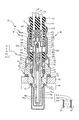
- Sectional drawing which shows the whole structure of the gas sensor 8 in the 1st Embodiment of this invention.
- Half sectional view of the terminal fitting of FIG. 2A 2B is a cross-sectional view showing the positional relationship between the cylindrical portion, the conductive portion, and the caulking portion by superimposing cross sections along CC, DD, and EE in FIG.
- Sectional drawing which shows the modification of the terminal metal fitting of FIG. 2A Sectional drawing for demonstrating the effect of the gas sensor in the 1st Embodiment of this invention
- the expanded sectional view which shows the outline
- FIG. 4A is a fragmentary cross-sectional view showing a process following the process shown in FIG. 4A.
- FIG. 4B is a fragmentary cross-sectional view showing a process following the process shown in FIG. 4B.
- Sectional drawing which shows the principal part which shows the gas sensor in the 2nd Embodiment of this invention.
- Sectional drawing which shows the principal part which shows the modification of the gas sensor in the 2nd Embodiment of this invention.
- Sectional drawing which shows the principal part which shows the gas sensor in the 3rd Embodiment of this invention.
- Sectional drawing which shows the principal part which shows the gas sensor in the 4th Embodiment of this invention.
- the longitudinal cross-sectional view which shows the gas sensor in the 5th Embodiment of this invention A longitudinal section showing a gas sensor in a 6th embodiment of the present invention.
- the longitudinal cross-sectional view which shows the modification of the gas sensor in the 6th Embodiment of this invention
- FIG. 2A, FIG. 2B, FIG. 2C, FIG. 2D, and FIG. 3 the outline
- the side exposed to the gas 91 to be measured is referred to as the distal end side
- the side from which the signal line 2 is drawn out is referred to as the proximal end side.
- the gas sensor 8 to which the present invention is applied uses a combustion exhaust gas or the like of an internal combustion engine such as an automobile engine or a motorcycle engine as a measured gas 91 and is fixed to the measured gas flow path 90 to detect a specific component in the measured gas. To do.
- an oxygen sensor using a solid electrolyte material having oxygen ion conductivity such as zirconia will be described as an example.
- a proton conductor or the like as the solid electrolyte material constituting the gas sensor element 3 depending on the detection target, or for detecting not only the oxygen concentration but also the air-fuel ratio, NOx, ammonia, etc. Is also possible.
- the gas sensor 8 includes a cylindrical water-repellent filter 61 that introduces air into the gas sensor element 3 and prevents moisture from entering.
- the water-repellent filter base end portion 611 is caulked together with the first cylindrical elastic member (hereinafter abbreviated as first elastic member) 4 and the signal line 2, and the base end side of the casing 5 is compressed and deformed. Sealed by a portion 54.
- a second cylindrical elastic member (hereinafter abbreviated as a second elastic member) 60 that elastically presses the casing 5 and the water repellent filter 61 between the casing 5 and the signal extraction portion 33 of the gas sensor element 3. Is provided.
- the water repellent filter front end portion 612 and the second elastic member 60 are backed by the front end side caulking portion 55 formed by compressively deforming the front end side of the casing 5 with the outer peripheral surface 331 of the signal extraction portion 33 of the gas sensor element 3 as the back. Sealed.
- the first elastic member 4 and the second elastic member 60 are disposed on the distal end side and the proximal end side of the water repellent filter 61, respectively, so that a gap is formed between the casing 5. It does not occur and reliably prevents the entry of water droplets from the outside, thereby improving durability.
- the gas sensor 8 in the present embodiment is a heaterless type gas sensor that is disposed near the exhaust pipe of the internal combustion engine and activates the solid electrolyte body by using the high temperature of the gas to be measured 91.
- the gas sensor 8 includes a terminal fitting 1, a signal line 2, a gas sensor element 3, a first elastic member 4, a casing 5, a second elastic member 60, a water-repellent filter 61, a housing 7, and other generally. It is comprised by the member (powder filling member 62, the insulating sealing member 63, the sealing member 64) used for a gas sensor.
- the gas sensor element 3 is a so-called cup-type element, and includes a detection unit 30 including a solid electrolyte body 300, a measurement electrode layer 310, and a reference electrode layer 320.
- the solid electrolyte body 300 is formed by forming a solid electrolyte material having conductivity with respect to specific ions into a bottomed cylindrical shape having one end closed and the other end opened.
- the measurement electrode layer 310 is formed on the outer peripheral surface 301 of the solid electrolyte body 300 and is in contact with the measurement gas 91.
- the reference electrode layer 320 is formed on the inner peripheral surface 321 of the solid electrolyte body 300 and is in contact with the atmosphere introduced into the reference gas chamber 32 as a reference gas.
- the gas sensor element 3 includes a detection unit 30, a diameter-enlarged part 31 whose part of the outer periphery is enlarged, a reference gas chamber 32 partitioned inside, and a signal extraction part 33 that is connected to the outside from the base end side. It is configured.
- the measurement electrode layer 310 and the reference electrode layer 320 are formed of a known porous electrode made of platinum or a platinum alloy.
- a reference gas chamber 32 into which air is introduced as a reference gas is defined inside the solid electrolyte body 300.
- the detection unit 30 is disposed in the gas to be measured 91, and the electromotive force generated by the difference between the oxygen concentration in the atmosphere introduced into the reference gas chamber 32 and the oxygen concentration in the gas to be measured causes The oxygen concentration can be detected.
- the reference electrode layer 320 is connected to the signal line 2 connected to the outside by the terminal fitting 1.
- the measurement electrode layer 310 is electrically connected to the measured gas flow path 90 via the housing 7 and is in a grounded state.
- a known signal line is used in which a core wire 20 made of a conductive material such as copper, aluminum, and stainless steel is embedded inside and the outside is covered with an insulating coating.
- the signal line 2 is intended to connect the gas sensor element 3 to the outside.
- a metal material having excellent heat resistance, conductivity, and elasticity such as stainless steel, iron, nickel, or an alloy thereof is used.
- the terminal fitting 1 in this embodiment includes a crimping portion 10 that crimps and fixes the core wire 20 of the signal line 2, a conduction portion 12 that establishes conduction with the reference electrode layer 320, and a first elastic member provided as a first elastic member.
- 4 is formed of a heat insulating layer forming cylindrical portion (hereinafter abbreviated as a cylindrical portion) 15 for forming a heat insulating space 322 between the bottom surface 40 of the gas sensor 4 and the gas sensor element 3 and connecting portions 11 and 13 connecting them.
- a cylindrical portion 15 for forming a heat insulating space 322 between the bottom surface 40 of the gas sensor 4 and the gas sensor element 3 and connecting portions 11 and 13 connecting them.
- the tubular portion 15 of the terminal fitting 1 forms a heat insulating space 322 between the bottom surface 40 of the first elastic member 4 and the solid electrolyte body 300, and the air holes 52 provided in the casing 5 are formed in the heat insulating space 322.
- the elasticity of the first elastic member 4 and the second elastic member 60 is used to base the cylindrical water repellent filter 61.
- the cylindrical portion 15 is formed in a partially cut-out cylindrical shape having a diameter larger than the inner diameter of the inner peripheral surface 321 of the solid electrolyte body 300 and extending in the axial direction with a C-shaped cross section.
- the cylindrical portion 15 is formed so as to protrude with a predetermined length from the base end side of the gas sensor element 3 when the terminal fitting 1 is attached to the solid electrolyte body 300.
- the element side abutting portion 14 is formed so as to abut on the flat portion 34 perpendicular to the longitudinal axis of the solid electrolyte body 300 on the distal end side of the cylindrical portion 15.
- the end surface on the base end side of the solid electrolyte body 300 is a flat portion 34.
- the proximal end contact portion 16 is formed to contact the bottom surface 40 of the first elastic member 4 on the proximal end side of the tubular portion 15. Moreover, the base end side contact part 16 in this embodiment is formed in the shape of a collar protruding in radial direction. By using the hook shape, it is possible to disperse the pressure that presses the bottom surface 40 of the first elastic member 4 and to prevent the local pressure from acting on the first elastic member 4 and causing cracks.
- the conducting part 12 has a slightly larger diameter than the inner diameter of the inner peripheral surface 321 of the solid electrolyte body 300, and is formed in a partially cut-out cylindrical shape having a C-shaped cross section and extending in the axial direction. Since the conducting portion 12 is urged in the outer diameter direction, when the conducting portion 12 is attached to the solid electrolyte body 300 while reducing the diameter, the conducting portion 12 is elastically brought into contact with the reference electrode layer 320 to achieve conduction. It can be done.
- the taper part 17 is provided so that a part of conduction
- the tip of the tapered portion 17 functions as an insertion guide, and the inner diameter 321 of the solid electrolyte body 300 is reduced in diameter while being reduced in diameter. It can be inserted smoothly.
- the crimping portion 10 is for crimping and fixing the core wire 20 of the signal line 2.
- the crimping portion 10 may be disposed concentrically, or FIG. As shown in FIG. 5, the cylindrical portion 15 may be arranged eccentrically so as to coincide with the outer peripheral edge of the conducting portion 12.
- the detection unit 30 includes a solid electrolyte body 300, a reference electrode layer 320 formed on the inside thereof and in contact with the atmosphere introduced as a reference gas, and a measurement electrode layer 310 formed on the outside thereof and in contact with the gas to be measured. In the state where it is protected by the cover body, it is arranged in the gas to be measured 91.
- the casing 5 is formed of a metal material such as iron, nickel, and stainless steel in a stepped cylindrical shape.
- the large-diameter portion 50 on the front end side of the casing 5 is fitted on the boss portion 74 of the housing 7 and is sealed and fixed by a welding portion 56 such as laser welding.
- a plurality of vent holes 52 are formed in the side surface of the middle diameter portion 51 of the casing 5 to introduce air into the casing 5.
- first elastic member 4 and the second elastic member 60 a heat-resistant elastic member selected from any one of fluorine rubber, silicone rubber, urethane rubber and the like is used.
- the first elastic member 4 and the second elastic member 60 are made of rubber having a rubber hardness of 50 to 90 (durometer A) determined according to JIS-K6253: 2006 or ISO 48: 1994 and ISO 7916-1: 2004. It is desirable that the elastic member be formed. JIS-K6253: 2006 corresponds to ISO48: 1994 and ISO16-1: 2004.
- the first elastic member 4 is cylindrical and the signal line 2 is inserted inside.
- a part of the outer periphery of the first elastic member 4 is provided with a flange portion 41 projecting toward the outer peripheral side, and a small diameter portion 42 having a small diameter is formed on the proximal end side.
- the flange portion 41 By providing the flange portion 41, the intrusion prevention of water droplets from the base end side of the casing 5 is further ensured.
- the base end side of the first elastic member 4 is exposed from the small diameter portion 53 of the casing 5, the pressure when the casing 5 is caulked is released, and the bottom surface 40 of the first elastic member 4 is connected to the terminal fitting 1. Except for the portion that contacts the proximal end side contact portion 16, the elasticity of the first elastic member 4 is not lost by expanding into the heat insulating space 322.
- the second elastic member 60 in the present embodiment is formed with taper portions 602 and 603 so as to be tapered at the base end side and the tip end side of the base portion 600 formed in a cylindrical shape (see FIG. 4A).
- the elasticity is not lowered by releasing the pressure when the two ends are swollen by being compressed by the front end side caulking portion 55 of FIG.
- the second elastic member 60 is disposed inside the water repellent filter 61, and the inner peripheral surface 601 of the second elastic member 60 has an inner diameter that can be attached to the signal extraction portion 33 of the gas sensor element 3. Is formed.
- the water repellent filter 61 is provided at a position facing the vent hole 52, allows gas to pass from the vent hole 52 to the inside of the sensor, and blocks liquid from passing therethrough.
- the water repellent filter 61 uses a porous fiber structure made of a fluororesin such as polytetrafluoroethylene and formed in a cylindrical shape.
- the base end portion 611 of the water repellent filter 61 is compressed and deformed by compressing and deforming the base end side of the middle diameter portion 51 of the casing 5 together with the first elastic member 4 and the signal line 2 to provide an airtight seal. It has been stopped.
- the distal end portion 612 of the water repellent filter 61 is a distal end formed by compressing and deforming the distal end side of the medium diameter joint portion 51 of the casing 5 with the second elastic member 60 and the outer peripheral surface 331 of the signal extraction portion 33 of the gas sensor element 3 as the back.
- a side caulking portion 55 is provided and hermetically sealed.
- the base end 611 of the water repellent filter 61 is always elastically pressed by the first elastic member 4 in a state where the signal line 2 is embedded.
- the tip 612 of the water repellent filter 61 is always elastically pressed by the second elastic member 60 supported by the outer peripheral surface 331 of the signal extraction part 33 of the gas sensor element 3. For this reason, even if the proximal end portion 611 and the distal end portion 612 of the water repellent filter 61 are creep-deformed by caulking, the close contact state is always maintained by the first elastic member 4 and the second elastic member 60.
- the housing 7 is made of a known heat-resistant metal material such as stainless steel, iron, nickel, iron-nickel alloy or the like, is formed in a cylindrical shape, and houses the gas sensor element 3 inside.
- a screw part 75 is formed on the outer periphery on the front end side of the housing 7 and is fixed to the gas flow path 90 to be measured, and the detector 30 is disposed and fixed in the gas 91 to be measured.
- a boss portion 74 is formed on the base end side of the housing 7, and a large diameter portion 50 of the casing 5 is mounted, and a welded portion 56 is formed and fixed in an airtight manner by a fixing means such as laser welding.
- the powder filling member 62 is formed by annularly forming a heat-resistant ceramic powder such as talc powder.
- the insulating sealing member 63 is formed by annularly forming a heat-resistant ceramic sintered body such as alumina.
- the seal member 64 is made of a stainless steel or the like formed of a metal material having high heat resistance in an annular shape.
- the diameter-enlarged portion 31 of the gas sensor element 3 is sandwiched between the element locking portion 71 and the caulking portion 73 formed in the housing 7 via the powder filling member 62, the insulating sealing member 63, and the seal member 64, and the axial force The airtightness is secured by loading. A part of the gas sensor element 3 is exposed from the base end side of the housing 7 to constitute a signal extraction part 33.
- the detection unit 30 of the gas sensor element 3 is exposed from the front end side of the housing 7 and is disposed in the measurement gas 91.
- the detection unit 30 is covered and protected by a cover body 78 fixed to the distal end side of the housing 7.
- An opening 79 is formed in the cover body 78 so that the gas to be measured 91 is introduced into the cover body 78.
- the shape of the cover body 78 and the position, size, number, etc. of the openings 79 are not particularly limited, and can be appropriately changed according to the application. It is not limited to a single one as shown in this figure, and a plurality of cover bodies arranged concentrically may be used.
- summary of the manufacturing method of the gas sensor 8 which concerns on this invention is demonstrated.
- the method of assembling the gas sensor element 3 to the housing 7 is not particularly limited, and a known assembling method can be employed, and thus will be omitted in the following description.
- the core wire 20 exposed from the tip of the signal line 2 that has passed through the casing 5 and the first elastic member 4 is crimped and fixed by the crimping portion 10 of the terminal fitting 1.
- the first elastic member 4 is disposed on the base end side of the casing 5, and the base end side contact portion 16 of the terminal fitting 1 is in contact with the bottom surface 40 of the first elastic member 4.
- the second elastic member 60 and the water-repellent filter 61 are arranged from the base end side of the gas sensor element 3 that is caulked and fixed in the housing 7 via a predetermined powder filling member 62, an insulating sealing member 63, a seal member 64, and the like.
- a casing 5 accommodating the terminal fitting 1 and the signal line 2 is attached.
- the conducting portion 12 provided on the distal end side of the terminal fitting 1 is press-fitted into the gas sensor element 3 while the tapered portion 17 serves as a guide and the conducting portion 12 is reduced in diameter.
- the conduction portion 12 is biased so as to elastically press the reference electrode layer 320 formed on the inner peripheral surface 321 of the gas sensor element 3 toward the outside, and is connected to the reference electrode layer 320 via the terminal fitting 1. Conduction with the signal line 2 is ensured.
- the proximal end side outer periphery and the distal end side outer periphery are compressed toward the center with the ventilation hole 52 interposed therebetween, and the proximal end side caulking portion 54 and the distal end A side caulking portion 55 is formed.
- the proximal end side caulking portion 54 and the distal end side caulking portion 55 are plastically deformed and do not return to the original shape.
- proximal end portion 611 and the distal end portion 612 of the water repellent filter 61 are compressed and deformed along the proximal end caulking portion 54 and the distal end side caulking portion 55 to be densified. Furthermore, the base end portion 611 of the water repellent filter 61 is elastically pressed from the inside by the first elastic member 4, and the tip end portion 612 is elastically pressed from the inside by the second elastic member 60, The close contact state is maintained.
- the first elastic member 4 has the signal line 2 embedded therein, exhibits substantially the same elasticity as the solid elastic member, and swells in the vertical direction.
- the bottom surface 40 of the first elastic member 4 elastically presses the proximal end side contact portion 16 of the cylindrical portion 15 of the terminal fitting 1 toward the gas sensor element 3, and the element side contact portion 14 becomes the gas sensor element 3. Therefore, the terminal fitting 1 is firmly held between the first elastic member 4 and the gas sensor element 3.
- the base end side of the casing 5 is open, and the exposed portion of the first elastic member 4 on the base end side swells outward. Except for the part where the bottom surface 40 of the first elastic member 4 and the flange-like base end side contact portion 16 of the terminal fitting 1 are in contact, the first elastic member 4 swells into the heat insulating space 322 provided on the distal end side.
- the 2nd elastic member 60 has the signal extraction part 33 of the gas sensor element 3 as the back, the pressure by crimping is disperse
- the second elastic member 60 is provided with taper portions 602 and 603, and there is a relief wall between the second elastic member 60 and the gas sensor element 3, so that excessive internal pressure does not remain and elasticity can be maintained. .
- the large diameter portion 50 provided on the front end side of the casing 5 is attached to the boss portion 74 provided on the housing 7, and the welded portion 56 is irradiated with laser light from the periphery thereof. It is provided and the front end side of the casing 5 is sealed and fixed to the housing 7. Thus, the gas sensor 8 is completed.
- the ingress of water droplets from both ends of the casing 5 is completely prevented, and the air introduced from the vent hole 52 formed in the middle diameter portion 51 of the casing 5 always uses the water repellent filter 61. Therefore, the water repellent filter 61 prevents moisture from entering the gas sensor 8. Condensation generated during cooling in the gas sensor element 3 becomes water vapor during use, passes through the water-repellent filter 61, and is discharged from the vent hole 52. Therefore, a highly reliable gas sensor 8 that is unlikely to cause water cracking can be realized. . Furthermore, as described above, the terminal fitting 1 is firmly held between the gas sensor element 3 and the first elastic member 4 while utilizing the elasticity of the first elastic member 4. Therefore, it is possible to sufficiently resist the axial vibration from the outside, and there is no possibility that conduction between the conduction portion 12 and the reference electrode layer 320 is momentarily interrupted.
- Modification examples 8a, 8b, 8c, and 8d of the gas sensor according to the first embodiment will be described with reference to FIGS. 5A, 5B, 5C, and 5D.
- the basic configuration is the same as that of the above embodiment except that the terminal fittings 1a, 1b, 1c, and 1d are used, and the gas sensor elements 3a, 3b, 3c, and 3d are used.
- the same components as those in the above embodiment are denoted by the same reference numerals, and the portions different from each other according to the respective modifications are denoted by alphabetical symbols as branch numbers. The explanation will focus on the characteristic points. The same applies to other embodiments.
- the terminal fitting 1a has a distal end with an inner peripheral surface 321a as the flat portion 34a in the signal extraction portion 33a provided on the proximal end side of the solid electrolyte body 300 in the gas sensor element 3a in the present embodiment.
- a stepped portion (34a) whose diameter is changed stepwise is provided so that the diameter becomes smaller and the proximal end side becomes larger.
- the cylindrical part 15a in order to utilize a part of cylindrical part 15a as the conduction
- the conducting portion 12a press-fitted inside the solid electrolyte body 300 elastically presses the inner peripheral surface 321a in the radial direction from the inside to achieve conduction with the reference electrode layer 320.
- the element side contact portion 14 a at the tip of the conducting portion 12 a is in contact with a stepped portion (planar portion) 34 a provided inside the solid electrolyte body 300 and is exposed to the base end side of the solid electrolyte body 300.
- the base end side contact portion 16 of the portion 15a is in contact with the bottom surface 40 of the first elastic member 4 and is elastically pressed.
- the first elastic member 4 maintains the adhesion between the proximal end side caulking portion 54 of the casing 5 and the water repellent filter base end portion 611, and the second elastic member 60.
- the adhesion between the caulking portion 55 on the front end side of the casing 5 and the front end portion 612 of the water repellent filter is maintained.
- the thermal insulation of the first elastic member 4 is suppressed by the heat insulating space 322.
- the step part (planar part) 34a Since the element-side contact portion 14a presses the reference electrode layer 320 formed on the surface in the axial direction, conduction between the terminal fitting 1a and the reference electrode layer 320 is ensured, and extremely high conduction reliability can be exhibited.
- the cylindrical portion 15b is formed in a notched cylindrical shape having a C-shaped cross section and extending in the axial direction.
- the outer diameter of the cylindrical portion 15 b is formed so as to be larger than the inner peripheral diameter of the solid electrolyte body 300.
- the conducting portion 12b is also formed in a cut-out cylindrical shape having a C-shaped cross section and extending in the axial direction.
- the outer diameter of the conducting portion 12b is formed to be slightly larger than the inner peripheral diameter of the solid electrolyte body 300, and is press-fitted inside the solid electrolyte body 300 in a reduced diameter state.
- the conduction portion 12b elastically presses the reference electrode layer 320 outward to ensure conduction. Also in the present embodiment, an excellent water immersion prevention function is exhibited as in the above embodiment. In addition, with the base end side end surface of the solid electrolyte body 300 as the flat portion 34, the element side contact portion 14 contacts, and the base end side contact portion that is not formed in a bowl shape on the bottom surface 40 of the first elastic member 4. 16b is in contact. Also in the present embodiment, the thermal degradation of the first elastic member 4 is suppressed by the heat insulating space 322 as in the above embodiment. In addition, in the present embodiment, the structure is simplified and the manufacturing cost is further reduced by adopting a configuration in which the collar portion and the inclined surface are eliminated.
- the diameter of the open end of the signal extraction portion 33c provided on the base end side of the solid electrolyte body 300 is gradually changed toward the base end side so as to include a vertical component.
- An inclined surface 34c is provided in the terminal fitting 1c in the present embodiment.
- an element side contact portion 14c is provided between the cylindrical portion 15d and the conducting portion 12d.
- the conduction part 12c is eliminated from the gas sensor 8c shown in 5C, and the element side contact part 14d also serves as the conduction part 12d. Even with such a configuration, the same effect as the above-described embodiment can be exhibited.
- the gas sensor 8e in the 2nd Embodiment of this invention is demonstrated.
- the configuration in which the second elastic member 60 is disposed inside the water repellent filter 61 is shown.
- the water repellent filter 61e is disposed inside the second elastic member 60e.
- the point and the point which used the terminal metal fitting 1e differ.
- the above-described terminal fittings 1, 1a, 1b, 1c, and 1d can be appropriately employed.
- the distal end portion 612e of the water repellent filter 61e and the second elastic member 60e are interposed between the casing 5 and the signal extraction portion 33 of the gas sensor element 3, and the outer peripheral surface 331 of the signal extraction portion 33.
- a caulking portion 55 is provided by compressing the middle diameter portion 51 of the casing 5 toward the center in the radial direction with the back facing.
- the deformed portion 323 is brought into contact with the reference electrode layer 320.
- the conduction reliability is complementarily improved by the second conduction portion 18.
- the second conducting portion 18 is formed in a tongue-like shape that is bifurcated on the distal end side, and presses in the axial direction and the radial direction by contacting the inclined diameter changing portion 323.
- the conduction portion 12 that elastically presses the reference electrode layer 320 in the radial direction and the reference electrode layer 320 in the axial and radial directions are neat. Since any one of the second conducting parts 18 to be pressed always maintains conduction with the reference electrode layer 320, extremely high conduction reliability can be exhibited.
- the modification 8f of the gas sensor in 2nd Embodiment is demonstrated.
- the example in which the crimping portion 10 for crimping the signal line 2 is provided at the tip of the terminal fitting 1 in the terminal fitting 1, 1a to 1e is shown, but in the present embodiment, as the terminal fitting 1f, A crimping portion 10h for crimping and fixing the core wire 20 of the signal line 2 is disposed at the center of the terminal fitting 1f, and a cylindrical portion 15 having a proximal end side contact portion 16 on the proximal end side via the connecting portion 13f.
- a conducting portion 12f is provided on the tip side via a connecting portion 11f. It should be noted that this modification can be combined with other embodiments except for some modifications.
- the element side contact portion 14 of the terminal fitting 1f contacts the flat portion 34 of the gas sensor element 3, and the proximal end side contact portion 16 Is in contact with the bottom surface 40 of the first elastic member 4, and a heat insulating space 322 is formed between the base end of the gas sensor element 3 and the first elastic member 4 through the water repellent filter 61 and connected to the vent hole 52.
- the gas sensor 8f in which the thermal degradation of the first elastic member 4 is suppressed and the conduction reliability between the conduction portion 12f of the terminal fitting 1f and the reference electrode layer 321 is excellent.
- the physique of the gas sensor 8f can be reduced. Furthermore, since the crimping part 10f is provided on the base end side with respect to the conducting part 12f, the distance from the heat source to the crimping part 10f is longer than the gas sensors 8 and 8a to 8e provided with the crimping part 10 at the distal end. The thermal damage to the insulation coating of the signal line 2 can be reduced.
- the gas sensor 8g in 3rd Embodiment is demonstrated.
- a terminal fitting 1g having a crimping portion 10g for connection to the signal line 2 provided on the base end side is used, and an insulator 66 formed in a cylindrical shape that accommodates the crimping portion 10g inside is provided. The point is different.
- the crimping portion 10g is provided on the proximal end side with respect to the cylindrical portion 15g.
- the crimping portion 10g is located on the proximal end side with respect to the vent hole 52 and is disposed in a relatively low temperature environment, so that thermal damage to the insulating coating of the signal line 2 can be reduced. it can.
- the insulator 66 is formed in an annular shape by using an insulating material such as alumina so that a space capable of accommodating the crimping portion 10g is provided inside, and is interposed between the cylindrical portion 15g and the bottom surface 40.
- the insulator 66 having high thermal conductivity comes into contact with the bottom surface 40 of the first elastic member 4, but the air holes 52 are formed on the tip side of the insulator 66 while being supported by the cylindrical portion 15 g. Since the heat insulating space 322 communicated with the atmosphere via the air exists on the tip side from the insulator 66, the heat of the gas to be measured for heating the gas sensor element 3 hardly reaches the first elastic member 4, and the first It becomes possible to suppress the thermal deterioration of the elastic member 4.
- the second elastic member 60 is disposed on the inner side of the tip portion 612 of the water repellent filter 61 .
- the tip 612e of the water repellent filter 61e may be disposed on the inner side of the second elastic member 60e.
- a crimping part space for accommodating the crimping part 10 g is provided on the distal end side of the first elastic member 4 so as to be accommodated inside the first elastic member 4. Also good.
- the gas sensor 8h in 4th Embodiment is demonstrated.
- the point which used the terminal metal fitting 1h is different.
- the second elastic member 60 is disposed on the inner side of the tip portion 612 of the water repellent filter 61.
- the tip 612e of the water repellent filter 61e may be disposed on the inner side of the second elastic member 60e.
- the reference electrode layer 320h formed on the inner peripheral surface 321h of the solid electrolyte body 300 is disposed on the outer periphery of the solid electrolyte body 300 at the signal extraction portion 33h formed on the base end side of the solid electrolyte body 300. It extends to the surface 331h. Also in the present embodiment, the heat deterioration of the first elastic member 4 is suppressed by forming the heat insulating space 322 between the first elastic member 4 and the gas sensor element 3h.
- a part of the cylindrical portion 15h of the terminal fitting 1h is fitted to the outer peripheral surface 331h of the solid electrolyte body 300 as a conducting portion 12h.
- the conducting portion 12h is formed in a cross-sectional C shape with a diameter slightly smaller than the outer diameter of the outer peripheral surface 331h of the solid electrolyte body 300, and the conducting portion 12h is fitted to the outer peripheral surface 331h. Sometimes it is biased to generate a pressing force in the direction from the outside toward the center.
- the conduction portion 12h elastically presses the reference electrode layer 320h from the outer peripheral side direction to achieve conduction.
- the outer diameter of the conducting portion 12h is increased, so that the surface area of the conducting portion 12h is increased, the cooling effect is improved, and the first elastic member It is also possible to reduce the amount of heat transfer to 4.
- the step portion provided on the outer periphery of the signal extraction portion 33h is a flat portion 34h, the element side contact portion 14h is contacted, and the base end side contact portion 16h of the cylindrical portion 15h is the first elastic member 4.
- the first elastic member 4 is also elastically pressed by the first elastic member 4 in the axial direction to improve the conduction reliability.
- the second elastic member 60 is fitted so as to cover the outer periphery of the conducting portion 12 h and is compressed together with the water repellent filter 61 from the outer peripheral direction by the caulking portion 55.
- the conduction portion 12h is biased so as to elastically press the reference electrode layer 320h extending on the outer peripheral surface 331h of the signal extraction portion 33h toward the center, but the second elastic member 60 is superimposed on the conductive portion 12h. Since the conduction portion 12h is elastically pressed toward the center, the one-phase conduction reliability can be further improved.
- the gas sensor 8i in 5th Embodiment is demonstrated.
- an example in which the casing 5 is fixed to the housing 7 by welding is shown.
- a flange 56i projecting in the outer peripheral direction is provided at the tip of the casing 5i, and the powder filling member 62i is insulated.
- the sealing member 63i and the seal member 64 are sandwiched between the powder filling portion locking portion 72 and the caulking portion 73i of the housing 7i, and are subjected to an axial force in the axial direction to be caulked and fixed. .
- FIG. 6 shows an example in which the terminal fitting 1 having the same configuration as the terminal fitting 1 used in the gas sensor 8 in the first embodiment is used, but any of the above-described terminal fittings 1a to 1h is appropriately adopted. can do. Also in this embodiment, the same effect as the above-described embodiment can be exhibited.
- the gas sensor 8j in 6th Embodiment is demonstrated.
- a so-called heaterless type gas sensor has been described.
- the present invention can also be applied to a gas sensor 8i including a shaft-shaped heater H as shown in the present embodiment. It should be noted that each modification in the embodiment may be adopted as appropriate.
- the gas sensor 8j in the present embodiment is connected to a gas sensor element 3j, a heater H that is provided inside the gas sensor element 3j and contains a heating element that generates heat when energized, and a pair of energized electrodes ELH provided at the base end of the heater H.
- a positive signal line 2P connected to the outside via the negative electrode metal fitting 1N connected to the measurement electrode layer 310, a negative signal line 2N connected externally via the negative terminal metal fitting 1N, and the base end side of the gas sensor element 3j The base end side of the casing 5j while holding the casing 5j covering the casing, the pair of energization lines 2H, the plus signal line 2P, and the minus signal line 2N
- the first elastic member 4j to be sealed, the cylindrical water repellent filter 61j provided to face the vent hole 52 formed in the casing 5j, the second elastic member 60j, and the housing 7j are included. .
- the cylindrical portion 41j provided on the distal end side of the first elastic member 4j and the proximal end side of the water repellent filter 61j are connected to the casing 5j.
- the second elastic member 60 j and the water repellent filter 61 j are caulked by the caulking portion 55 at the distal end side of the casing 5 with the signal extraction portion 33 j of the gas sensor element 3 j as the back.
- the air tightness of both ends of the water filter 61j can be maintained, and entry of water droplets from the outside can be prevented.
- the conductive portion 12N of the minus terminal fitting 1N connected to the measurement electrode layer 310 is projected from the base end side of the gas sensor element 3j to form a heat insulating space forming cylindrical portion 15j, and the base end side contact The contact portion 16j is brought into contact with the bottom surface of the insulator 66j to form a heat insulating space 322j.
- the modification 8k of the gas sensor in 6th Embodiment is demonstrated.
- a flange 56k projecting in the outer peripheral direction is provided at the tip of the casing 5k, and together with the powder filling member 62k, the insulating sealing member 63k, the seal member 64, the powder filling portion locking portion 72 of the housing 7k, etc. It is different in that it is sandwiched between the crimping portions 73k, is axially loaded and is caulked and fixed.
- the modification in the said embodiment can also be employ
- this invention is not limited to the said embodiment, In the range which does not deviate from the meaning of this invention, it can change suitably.
- an oxygen concentration sensor in which an electrode layer is formed on the inner and outer surfaces of an oxygen ion conductive solid electrolyte body as the concentration detection element has been described.
- an NOx sensor in which a solid electrolyte body is formed, an ammonia sensor using a proton conductor as a solid electrolyte body, and the like.
Landscapes
- Chemical & Material Sciences (AREA)
- Life Sciences & Earth Sciences (AREA)
- Health & Medical Sciences (AREA)
- Physics & Mathematics (AREA)
- Chemical Kinetics & Catalysis (AREA)
- Electrochemistry (AREA)
- Molecular Biology (AREA)
- Analytical Chemistry (AREA)
- Biochemistry (AREA)
- General Health & Medical Sciences (AREA)
- General Physics & Mathematics (AREA)
- Immunology (AREA)
- Pathology (AREA)
- Measuring Oxygen Concentration In Cells (AREA)
Abstract
固体電解質体300と測定電極層310と基準電極層320からなる検出部30を具備するガスセンサ素子3と、信号線2と、端子金具1と、ハウジング7と、通気孔52を備えたケーシング5と、第1の筒状弾性部材4と、撥水フィルタ61と、を具備し、被測定ガス91中の特定成分を検出するガスセンサであって、撥水フィルタ61の基端部611は、第1の筒状弾性部材4と、信号線2と共にケーシング5の基端側を圧縮変形した基端側かしめ部54によって封止し、撥水フィルタ61の先端部612は、第2の筒状弾性部材60と共に、ガスセンサ素子3の信号取出部33の外周面331を背にして、ケーシング5の先端側を圧縮変形した先端側かしめ部55によって封止する。
Description
本発明は、自動車エンジン等の燃焼排気中の特定ガス成分濃度を検出するガスセンサの構造に関するものである。
従来、自動車エンジン等の内燃機関の燃焼排気流路に、燃焼排気中に含まれる酸素等の特定ガス成分の濃度を検知するガスセンサを配設して、検知された特定ガス成分の濃度によって空燃比制御や排気処理触媒の温度制御等を行っている。
このようなガスセンサとして、ジルコニア等の酸素イオン伝導性固体電解質の基体表面に被測定ガスに接する測定電極層と基準ガスとして導入された大気に接する基準電極層とを施した酸素濃度検出素子を具備した酸素センサ等が広く用いられている。このような酸素センサは、被測定ガス中の酸素濃度と基準ガス中の酸素濃度との差によって両電極間に発生する電位差を検出して被測定ガス中の酸素濃度を測定している。
さらに、このようなガスセンサは、通常極めて高温の環境下で使用され、また、エンジンルーム以外に車両の足回りに近い排気管等にも搭載され、厳しい環境下に晒されている。
ガスセンサは、外部からの水滴等の侵入があるとガス濃度検出素子の破損や誤動作を招く虞があり、これを防止するために高い防水性が必要とされている。
一方、ガスセンサの基準電極層は基準ガスとなる大気に接しなければならず、外部との良好な通気性が確保されなければならない。
このため、ガスセンサにおいては防水性と通気性との二律背反する課題を同時に解決する必要がある。
ガスセンサは、外部からの水滴等の侵入があるとガス濃度検出素子の破損や誤動作を招く虞があり、これを防止するために高い防水性が必要とされている。
一方、ガスセンサの基準電極層は基準ガスとなる大気に接しなければならず、外部との良好な通気性が確保されなければならない。
このため、ガスセンサにおいては防水性と通気性との二律背反する課題を同時に解決する必要がある。
特許文献1には、筒状の検出素子と、検出素子を保持する主体金具と、検出素子と電気的に接続する端子金具と、端子金具からのびで電流経路を形成するリード線とリード線が挿通されるセパレータと、セパレータの周囲を取り囲む内筒と、内筒の筒孔内に配置されてリード線が挿通されるグロメットと、内径の径方向外側に配置されるフィルタと、内筒との間にフィルタを介在させる外筒とを備え、セパレータが検出素子とグロメットとにより挟持されることによって内筒から離間したガスセンサが開示されている。
外筒と内筒との間に介装したフィルタを固定するためには、外筒に降伏値を超える圧力を加えて塑性変形させ、変形部分が元の形状に戻らないようにする必要がある。
外筒と内筒との間に介装したフィルタを固定するためには、外筒に降伏値を超える圧力を加えて塑性変形させ、変形部分が元の形状に戻らないようにする必要がある。
ところが、特許文献1にあるような従来のガスセンサでは、内筒がセパレータから離間しているため、外筒を圧縮して塑性変形させてフィルタを加締め固定したときに、フィルタと内筒も塑性変形して、内筒の弾性力が失われることになる。
このような状態で冷熱環境に晒されると、内筒と外筒とフィルタとの間に間隙が発生し、水滴の侵入を許し、検出素子の被水割れを発生する虞がある。
また、内筒の弾性を失わせない程度の弱い力で外筒を加締めた場合には、外筒の加締めが不十分となり、復元力によって外筒とフィルタとの間に間隙が形成される虞もある。
このような状態で冷熱環境に晒されると、内筒と外筒とフィルタとの間に間隙が発生し、水滴の侵入を許し、検出素子の被水割れを発生する虞がある。
また、内筒の弾性を失わせない程度の弱い力で外筒を加締めた場合には、外筒の加締めが不十分となり、復元力によって外筒とフィルタとの間に間隙が形成される虞もある。
加えて、特許文献1にあるような従来のガスセンサでは、端子金具を絶縁保持するセパレータを検出素子とグロメットとで挟持する構造であるため、検出素子の基端側開口部がセパレータで覆われた状態となる。
このため、検出素子内へ基準ガスとして導入する大気の循環が阻害され、基準ガス中の酸素濃度が変動して出力に誤差を生じる虞もある。
さらに、高温の被測定ガスからの熱がセパレータに蓄熱され、セパレータに広い面積で接するグロメットの熱劣化を招く虞もある。
このため、検出素子内へ基準ガスとして導入する大気の循環が阻害され、基準ガス中の酸素濃度が変動して出力に誤差を生じる虞もある。
さらに、高温の被測定ガスからの熱がセパレータに蓄熱され、セパレータに広い面積で接するグロメットの熱劣化を招く虞もある。
本発明は、かかる実情に鑑みてなされたものであり、簡易な構造で、基準ガスとしての大気の導入は容易でありながらも水滴の侵入が起こり難く、耐久性に優れた構造のガスセンサを提供するものである。
本発明のガスセンサは、少なくとも、特定イオンに対して伝導性を有する有底筒状の固体電解質体と、該固体電解質体の外周表面に形成され、被測定ガスに接する測定電極層と、前記固体電解質体の内周表面に形成され、基準ガスとして導入した大気に接する基準電極層とからなる検出部を具備している。また、被測定ガス中の特定成分を検出するガスセンサ素子と、該ガスセンサ素子と外部との接続を図る信号線と、前記ガスセンサ素子と前記信号線との接続を図る端子金具と、前記ガスセンサ素子を収容し、前記検出部を被測定ガス中に配設・固定するハウジングと、前記ガスセンサ素子の基端側を前記端子金具と共に覆いつつ、内側に大気を導入する通気孔を備えた筒状のケーシングとを具備している。さらに、該ケーシングの基端側を気密に封止しつつ、前記端子金具に接続された前記信号線を保持する第1の筒状弾性部材と、前記通気孔に対向して設けられ、気体の透過は許容し液体の透過は阻止する多孔質繊維構造体を筒状に形成した撥水フィルタと、を具備し、被測定ガス中の特定成分を検出するガスセンサである。前記撥水フィルタの基端部は、前記第1の筒状弾性部材と前記信号線と共に、前記ケーシングの基端側を圧縮変形した基端側かしめ部によって封止し、前記ケーシングと前記ガスセンサ素子の信号取出部との間に、前記ケーシング及び前記撥水フィルタを弾性的に押圧する第2の筒状弾性部材を設けている。また、前記撥水フィルタの先端部は、前記第2の筒状弾性部材と共に、前記信号取出部の外周面を背にして、前記ケーシングの先端側を圧縮変形した先端側かしめ部によって封止している。
本発明によれば、前記撥水フィルタの基端部は前記信号線を埋設した状態の前記第1の筒状弾性部材によって常に弾性的に押圧されることになり、前記撥水フィルタの先端部は、前記信号取出部の外周面によって支えられた状態の前記第2の筒状弾性部材によって常に弾性的に押圧されることになる。
このため、加締めにより、前記撥水フィルタの基端部及び先端部がクリープ変形しても、前記第1の筒状弾性部材及び前記第2の筒状弾性部材によって常に密着状態が維持されるので、前記基端側かしめ部及び前記先端側かしめ部のいずれの側からも水滴が侵入するおそれがなく、前記通気路を通過して前記ガスセンサ内に導入される大気は、確実に前記撥水フィルタを透過し、ガスセンサ内への水滴の侵入が阻止されることになる。
したがって、極めて簡易な構成により、信頼性の高いガスセンサを実現できる。
このため、加締めにより、前記撥水フィルタの基端部及び先端部がクリープ変形しても、前記第1の筒状弾性部材及び前記第2の筒状弾性部材によって常に密着状態が維持されるので、前記基端側かしめ部及び前記先端側かしめ部のいずれの側からも水滴が侵入するおそれがなく、前記通気路を通過して前記ガスセンサ内に導入される大気は、確実に前記撥水フィルタを透過し、ガスセンサ内への水滴の侵入が阻止されることになる。
したがって、極めて簡易な構成により、信頼性の高いガスセンサを実現できる。
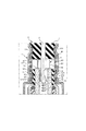
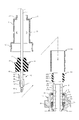
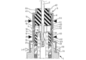
図1、図2A、図2B、図2C、図2D、図3を参照して、本発明の第1の実施形態におけるガスセンサ8の概要について説明する。
なお、以下の説明において、被測定ガス91に露出する側を先端側、信号線2を引き出す側を基端側と称する。
本発明の適用されるガスセンサ8は、自動車エンジン、自動二輪車エンジン等の内燃機関の燃焼排気等を被測定ガス91とし、被測定ガス流路90に固定され、被測定ガス中の特定成分を検出する。
なお、本発明の理解を容易にするため、以下の説明においては、ジルコニア等の酸素イオン伝導性を有する固体電解質材料を用いた酸素センサを例に説明するが、本発明において、検出対象を限定するものではなく、検出対象に応じて、ガスセンサ素子3を構成する固体電解質材料としてプロトン伝導体等を用いたり、酸素濃度だけでなく、空燃比、NOx、アンモニア等の検出に利用したりすることも可能である。
なお、以下の説明において、被測定ガス91に露出する側を先端側、信号線2を引き出す側を基端側と称する。
本発明の適用されるガスセンサ8は、自動車エンジン、自動二輪車エンジン等の内燃機関の燃焼排気等を被測定ガス91とし、被測定ガス流路90に固定され、被測定ガス中の特定成分を検出する。
なお、本発明の理解を容易にするため、以下の説明においては、ジルコニア等の酸素イオン伝導性を有する固体電解質材料を用いた酸素センサを例に説明するが、本発明において、検出対象を限定するものではなく、検出対象に応じて、ガスセンサ素子3を構成する固体電解質材料としてプロトン伝導体等を用いたり、酸素濃度だけでなく、空燃比、NOx、アンモニア等の検出に利用したりすることも可能である。
ガスセンサ8では、ガスセンサ素子3の内部に大気は導入しつつ、水分の侵入は阻止する筒状の撥水フィルタ61を具備する。
ガスセンサ8では、撥水フィルタ基端部611を第1の筒状弾性部材(以下、第1弾性部材と略す)4と信号線2と共に、ケーシング5の基端側を圧縮変形した基端側かしめ部54によって封止してある。
加えて、ケーシング5とガスセンサ素子3の信号取出部33との間に、ケーシング5及び撥水フィルタ61を弾性的に押圧する第2の筒状弾性部材(以下、第2弾性部材と略す)60を設けてある。
ガスセンサ8では、撥水フィルタ基端部611を第1の筒状弾性部材(以下、第1弾性部材と略す)4と信号線2と共に、ケーシング5の基端側を圧縮変形した基端側かしめ部54によって封止してある。
加えて、ケーシング5とガスセンサ素子3の信号取出部33との間に、ケーシング5及び撥水フィルタ61を弾性的に押圧する第2の筒状弾性部材(以下、第2弾性部材と略す)60を設けてある。
さらに、撥水フィルタ先端部612と、第2弾性部材60と、をガスセンサ素子3の信号取出部33の外周面331を背にして、ケーシング5の先端側を圧縮変形した先端側かしめ部55によって封止してある。
本発明のガスセンサ8では、撥水フィルタ61の先端側と基端側とそれぞれに、第1弾性部材4と第2弾性部材60とが配設されることによって、ケーシング5との間に隙間が生じることがなく、外部からの水滴の侵入を確実に阻止し、耐久性の向上を図ろうとするものである。
本発明のガスセンサ8では、撥水フィルタ61の先端側と基端側とそれぞれに、第1弾性部材4と第2弾性部材60とが配設されることによって、ケーシング5との間に隙間が生じることがなく、外部からの水滴の侵入を確実に阻止し、耐久性の向上を図ろうとするものである。
本実施形態におけるガスセンサ8は、内燃機関の排気筒に近い位置に配設され被測定ガス91の高い温度を利用して固体電解質体を活性化するヒータレスタイプのガスセンサである。
ガスセンサ8は、端子金具1と、信号線2とガスセンサ素子3と、第1弾性部材4と、ケーシング5と、第2弾性部材60と、撥水フィルタ61と、ハウジング7と、その他一般的にガスセンサに用いられる部材(粉末充填部材62、絶縁性封止部材63、シール部材64)によって構成されている。
ガスセンサ8は、端子金具1と、信号線2とガスセンサ素子3と、第1弾性部材4と、ケーシング5と、第2弾性部材60と、撥水フィルタ61と、ハウジング7と、その他一般的にガスセンサに用いられる部材(粉末充填部材62、絶縁性封止部材63、シール部材64)によって構成されている。
ガスセンサ素子3は、いわゆるコップ型の素子となっており、固体電解質体300と、測定電極層310と、基準電極層320とからなる検出部30を具備する。
固体電解質体300は、特定イオンに対して伝導性を有する固体電解質材料を一端が閉塞し他端が開口する有底筒状に形成したものである。測定電極層310は、固体電解質体300の外周表面301に形成され、被測定ガス91に接する。基準電極層320は、固体電解質体300の内周表面321に形成され、基準ガスとして基準ガス室32内に導入した大気に接する。
固体電解質体300は、特定イオンに対して伝導性を有する固体電解質材料を一端が閉塞し他端が開口する有底筒状に形成したものである。測定電極層310は、固体電解質体300の外周表面301に形成され、被測定ガス91に接する。基準電極層320は、固体電解質体300の内周表面321に形成され、基準ガスとして基準ガス室32内に導入した大気に接する。
ガスセンサ素子3は、検出部30と、外周の一部を拡径した拡径部31と、内側に区画した基準ガス室32と、基端側から外部との接続を図る信号取出部33とによって構成されている。
測定電極層310、基準電極層320は、白金又は白金合金からなる公知の多孔質電極によって形成されている。
固体電解質体300の内側には基準ガスとして大気が導入される基準ガス室32が区画されている。
検出部30は、被測定ガス91内に配設され、基準ガス室32内に導入した大気中の酸素濃度と被測定ガス中の酸素濃度との差によって生じる起電力によって、被測定ガス中の酸素濃度を検出することができる。
測定電極層310、基準電極層320は、白金又は白金合金からなる公知の多孔質電極によって形成されている。
固体電解質体300の内側には基準ガスとして大気が導入される基準ガス室32が区画されている。
検出部30は、被測定ガス91内に配設され、基準ガス室32内に導入した大気中の酸素濃度と被測定ガス中の酸素濃度との差によって生じる起電力によって、被測定ガス中の酸素濃度を検出することができる。
基準電極層320は、端子金具1によって外部に接続する信号線2と接続されている。
測定電極層310は、ハウジング7を介して、被測定ガス流路90に電気的に接続され、接地状態となっている。
測定電極層310は、ハウジング7を介して、被測定ガス流路90に電気的に接続され、接地状態となっている。
信号線2は、内側に銅、アルミニウム、ステンレス等の導電性材料からなる芯線20を埋設し、外側を絶縁被覆で覆った公知の信号線が用いられている。信号線2は、ガスセンサ素子3と外部との接続を図っている。
本実施形態における端子金具1は、ステンレス、鉄、ニッケル、又は、これらの合金等の耐熱性、導電性、弾性に優れた金属材料が用いられている。
本実施形態における端子金具1は、ステンレス、鉄、ニッケル、又は、これらの合金等の耐熱性、導電性、弾性に優れた金属材料が用いられている。
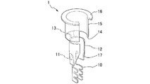
本実施形態における端子金具1は、信号線2の芯線20を圧着固定する圧着部10と、基準電極層320との導通を図る導通部12と、第1弾性部材として設けられた第1弾性部材4の底面40とガスセンサ素子3との間に断熱空間322を形成するための断熱層形成用筒状部(以下、筒状部と略す)15とこれらを連結する連結部11、13とによって構成されている。
本発明では、端子金具1の筒状部15によって、第1弾性部材4の底面40と固体電解質体300との間に断熱空間322を形成し、ケーシング5に設けた通気孔52を断熱空間322に連通させ、さらに、通気孔52に対向させた撥水フィルタ61をかしめ固定するに際して、第1弾性部材4と第2弾性部材60の弾性を利用して、筒状の撥水フィルタ61の基端側と先端側とのケーシング5の中径部51との間に隙間が生じないようにすることで、ガスセンサ素子3内部に導入する大気を、確実に撥水フィルタ61を通過させ、水滴の侵入阻止を確実なものとしている。
本発明では、端子金具1の筒状部15によって、第1弾性部材4の底面40と固体電解質体300との間に断熱空間322を形成し、ケーシング5に設けた通気孔52を断熱空間322に連通させ、さらに、通気孔52に対向させた撥水フィルタ61をかしめ固定するに際して、第1弾性部材4と第2弾性部材60の弾性を利用して、筒状の撥水フィルタ61の基端側と先端側とのケーシング5の中径部51との間に隙間が生じないようにすることで、ガスセンサ素子3内部に導入する大気を、確実に撥水フィルタ61を通過させ、水滴の侵入阻止を確実なものとしている。
筒状部15は、固体電解質体300の内周面321の内径よりも径大で、断面C字形で軸方向に伸びる一部切り欠き筒状に形成されている。
筒状部15は、端子金具1を固体電解質体300に装着したときにガスセンサ素子3の基端側から所定の長さで突出するように形成されている。
筒状部15は、端子金具1を固体電解質体300に装着したときにガスセンサ素子3の基端側から所定の長さで突出するように形成されている。
素子側当接部14は、筒状部15の先端側において固体電解質体300の長手軸に垂直な平面部34に当接するように形成されている。本実施形態においては、固体電解質体300の基端側端面を平面部34としている。
基端側当接部16は、筒状部15の基端側において第1弾性部材4の底面40に当接するように形成されている。
また本実施形態における基端側当接部16は、径方向に張り出す鍔状に形成されている。
鍔状とすることで、第1弾性部材4の底面40を押圧する圧力を分散させ、第1弾性部材4に局所的な圧力が作用して亀裂を生じるのを防ぐことができる。
また本実施形態における基端側当接部16は、径方向に張り出す鍔状に形成されている。
鍔状とすることで、第1弾性部材4の底面40を押圧する圧力を分散させ、第1弾性部材4に局所的な圧力が作用して亀裂を生じるのを防ぐことができる。
導通部12は、固体電解質体300の内周面321の内径よりも僅かに大きい径で、断面C字形で軸方向に伸びる一部切り欠き筒状に形成されている。
導通部12は、外径方向に付勢されているので、導通部12を縮径しながら固体電解質体300に装着したとき、基準電極層320と弾性的に当接して、導通を図ることでできるようになっている。
導通部12は、外径方向に付勢されているので、導通部12を縮径しながら固体電解質体300に装着したとき、基準電極層320と弾性的に当接して、導通を図ることでできるようになっている。
また、本実施形態においては、導通部12の一部が先端先細りとなるように、テーパ部17が設けてある。
テーパ部17を形成することによって、端子金具1を固体電解質体300に装着する際に、テーパ部17の先端が挿入ガイドとして機能し、縮径しながら固体電解質体300の内周面321内にスムーズに挿入することができる。圧着部10は、信号線2の芯線20を圧着固定するものである。
テーパ部17を形成することによって、端子金具1を固体電解質体300に装着する際に、テーパ部17の先端が挿入ガイドとして機能し、縮径しながら固体電解質体300の内周面321内にスムーズに挿入することができる。圧着部10は、信号線2の芯線20を圧着固定するものである。
なお、連結部11、13に傾斜を設けることで、図2Cに示すように、圧着部10と導通部12と筒状部15とが同心となるように配設しても良いし、図2Dに示すように、筒状部15の位置を導通部12の外周縁に一致するように偏心させて配設しても良い。
検出部30は、固体電解質体300と、その内側に形成され基準ガスとして導入された大気に接する基準電極層320と、その外側に形成され、被測定ガスに接する測定電極層310とによって構成され、カバー体によって保護された状態で、被測定ガス91内に配設されている。
ケーシング5は、鉄、ニッケル、ステンレス等の金属材料を段付き筒状に形成してある。
ケーシング5の先端側大径部50は、ハウジング7のボス部74に嵌着され、レーザ溶接等の溶接部56によって封止固定されている。
ケーシング5の中径部51の側面には、複数の通気孔52が穿設され、ケーシング5の内側に大気を導入している。
ケーシング5の先端側大径部50は、ハウジング7のボス部74に嵌着され、レーザ溶接等の溶接部56によって封止固定されている。
ケーシング5の中径部51の側面には、複数の通気孔52が穿設され、ケーシング5の内側に大気を導入している。
第1弾性部材4、及び、第2弾性部材60には、フッ素ゴム、シリコーンゴム、ウレタンゴム等のいずれかから選択した耐熱性弾性部材が用いられている。
尚、第1弾性部材4と第2弾性部材60とは、JIS-K6253:2006、又は、ISO48:1994及びISO7916-1:2004により求めたゴム硬度が50~90(デュロメータA)のゴム等からなる弾性部材によって形成するのが望ましい。
なお、JIS-K6253:2006は、ISO48:1994及びISO16-1:2004に相当するものである。第1弾性部材4、第2弾性部材60のゴム硬度をこの範囲に設定することによって、最も効果的に、撥水フィルタ61のクリープを補完できる。
尚、第1弾性部材4と第2弾性部材60とは、JIS-K6253:2006、又は、ISO48:1994及びISO7916-1:2004により求めたゴム硬度が50~90(デュロメータA)のゴム等からなる弾性部材によって形成するのが望ましい。
なお、JIS-K6253:2006は、ISO48:1994及びISO16-1:2004に相当するものである。第1弾性部材4、第2弾性部材60のゴム硬度をこの範囲に設定することによって、最も効果的に、撥水フィルタ61のクリープを補完できる。
第1弾性部材4は、筒状で、内側に信号線2が挿入されている。
第1弾性部材4の外周の一部には、外周側に向かって張り出す鍔部41が設けられ、基端側には径小となる小径部42が形成されている。
鍔部41を設けることで、ケーシング5の基端側からの水滴の侵入防止をより一層確実なものとしている。
また、第1弾性部材4の基端側はケーシング5の小径部53から露出しており、ケーシング5を加締めたときの圧力を開放し、第1弾性部材4の底面40は、端子金具1の基端側当接部16と当接する部分以外は、断熱空間322内に膨出することで、第1弾性部材4の弾性が失われないようになっている。
第1弾性部材4の外周の一部には、外周側に向かって張り出す鍔部41が設けられ、基端側には径小となる小径部42が形成されている。
鍔部41を設けることで、ケーシング5の基端側からの水滴の侵入防止をより一層確実なものとしている。
また、第1弾性部材4の基端側はケーシング5の小径部53から露出しており、ケーシング5を加締めたときの圧力を開放し、第1弾性部材4の底面40は、端子金具1の基端側当接部16と当接する部分以外は、断熱空間322内に膨出することで、第1弾性部材4の弾性が失われないようになっている。
本実施形態における第2弾性部材60は、筒状に形成された基部600の基端側と先端側とに先細りとなるようにテーパ部602、603が形成されており(図4A参照)、ケーシング5の先端側かしめ部55によって圧縮されて、両端が膨らんだときの圧力を逃がすことで、弾性が低下しないようになっている。
また、本実施形態においては、第2弾性部材60が撥水フィルタ61の内側に配設され、第2弾性部材60の内周面601はガスセンサ素子3の信号取出部33に装着可能な内径に形成されている。
また、本実施形態においては、第2弾性部材60が撥水フィルタ61の内側に配設され、第2弾性部材60の内周面601はガスセンサ素子3の信号取出部33に装着可能な内径に形成されている。
撥水フィルタ61は、通気孔52に対向する位置に設けられ、通気孔52からセンサ内部への気体の透過を許容し、液体の透過は阻止する。
撥水フィルタ61は、ポリテトラフルオロエチレン等のフッ素樹脂からなり筒状に形成された多孔質繊維構造体が用いられている。
撥水フィルタ61は、ポリテトラフルオロエチレン等のフッ素樹脂からなり筒状に形成された多孔質繊維構造体が用いられている。
撥水フィルタ61の基端部611は、第1弾性部材4と信号線2と共に、ケーシング5の中径部51の基端側を圧縮変形して基端側かしめ部54を設けて気密に封止されている。
撥水フィルタ61の先端部612は、第2弾性部材60と共に、ガスセンサ素子3の信号取出部33の外周面331を背にして、ケーシング5の中径継部51の先端側を圧縮変形した先端側かしめ部55を設けて気密に封止されている。
撥水フィルタ61の先端部612は、第2弾性部材60と共に、ガスセンサ素子3の信号取出部33の外周面331を背にして、ケーシング5の中径継部51の先端側を圧縮変形した先端側かしめ部55を設けて気密に封止されている。
撥水フィルタ61の基端部611は、信号線2を埋設した状態の第1弾性部材4によって常に弾性的に押圧されている。撥水フィルタ61の先端部612は、ガスセンサ素子3の信号取出部33の外周面331によって支えられた状態の第2弾性部材60によって常に弾性的に押圧されている。
このため、加締めにより、撥水フィルタ61の基端部611及び先端部612がクリープ変形しても、第1弾性部材4及び第2弾性部材60によって常に密着状態が維持される。
このため、加締めにより、撥水フィルタ61の基端部611及び先端部612がクリープ変形しても、第1弾性部材4及び第2弾性部材60によって常に密着状態が維持される。
したがって、基端側かしめ部54及び先端側かしめ部55のいずれの側からも水滴が侵入するおそれがなく、通気孔52を通過してガスセンサ8内に導入される大気は、確実に撥水フィルタ61を透過し、ガスセンサ8内への水滴の侵入が阻止されることになる。
ハウジング7は、ステンレス、鉄、ニッケル、鉄ニッケル合金等の公知の耐熱性金属材料が用いられ、筒状に形成され、内側にガスセンサ素子3を収容する。
ハウジング7の先端側外周にはネジ部75が形成され、被測定ガス流路90に固定され、検出部30を被測定ガス91中に配設・固定する。
ハウジング7の基端側には、ボス部74が形成され、ケーシング5の大径部50が装着され、レーザ溶接等の固定手段により溶接部56を形成し気密に固定している。
ハウジング7の先端側外周にはネジ部75が形成され、被測定ガス流路90に固定され、検出部30を被測定ガス91中に配設・固定する。
ハウジング7の基端側には、ボス部74が形成され、ケーシング5の大径部50が装着され、レーザ溶接等の固定手段により溶接部56を形成し気密に固定している。
粉末充填部材62には、タルク粉末等の耐熱性セラミック粉末を環状に形成したものが用いられている。
絶縁性封止部材63には、アルミナ等の耐熱性セラミック焼結体を環状に形成したものが用いられている。
シール部材64は、ステンレス等に耐熱性の高い金属材料を環状に形成したものが用いられている。
絶縁性封止部材63には、アルミナ等の耐熱性セラミック焼結体を環状に形成したものが用いられている。
シール部材64は、ステンレス等に耐熱性の高い金属材料を環状に形成したものが用いられている。
ガスセンサ素子3の拡径部31を、粉末充填部材62、絶縁性封止部材63、シール部材64を介して、ハウジング7に形成した素子係止部71とかしめ部73とで挟持し、軸力を負荷することで気密性を確保している。
ハウジング7の基端側からガスセンサ素子3の一部が露出し、信号取出部33を構成している。
ハウジング7の基端側からガスセンサ素子3の一部が露出し、信号取出部33を構成している。
またハウジング7の先端側からガスセンサ素子3の検出部30が露出し、被測定ガス91中に配設されている。検出部30は、ハウジング7の先端側に固定されたカバー体78によって覆われ、保護されている。
カバー体78には、開口部79が穿設され、被測定ガス91をカバー体78内に導入するようになっている。
本発明において、カバー体78の形状や、開口部79の位置、大きさ、数等を特に限定するものではなく、用途に応じて適宜変更することができる。
本図に示したような、単数のものに限らず、複数のカバー体を同心に配設したものを用いても良い。
カバー体78には、開口部79が穿設され、被測定ガス91をカバー体78内に導入するようになっている。
本発明において、カバー体78の形状や、開口部79の位置、大きさ、数等を特に限定するものではなく、用途に応じて適宜変更することができる。
本図に示したような、単数のものに限らず、複数のカバー体を同心に配設したものを用いても良い。
図4A、図4B、図4Cを参照して、本発明に係るガスセンサ8の製造方法の概要について、説明する。
なお、ガスセンサ素子3のハウジング7への組付方法は特に限定するものでなく、公知の組付方法を採用することができるため、以下の説明においては省略する。
なお、ガスセンサ素子3のハウジング7への組付方法は特に限定するものでなく、公知の組付方法を採用することができるため、以下の説明においては省略する。
図4Aに示すように、ケーシング5、第1弾性部材4を通した信号線2の先端から露出する芯線20を端子金具1の圧着部10によって圧着固定する。この状態で信号線2を引き戻しつつ、ケーシング5の基端側に第1弾性部材4を配設し、端子金具1の基端側当接部16を第1弾性部材4の底面40に当接させる。
次いで、ハウジング7内に所定の粉末充填部材62、絶縁性封止部材63、シール部材64等を介して加締め固定したガスセンサ素子3の基端側から、第2弾性部材60、撥水フィルタ61を装着し、さらに、図4Bに示すように、端子金具1、信号線2が収容されたケーシング5を装着する。
次いで、ハウジング7内に所定の粉末充填部材62、絶縁性封止部材63、シール部材64等を介して加締め固定したガスセンサ素子3の基端側から、第2弾性部材60、撥水フィルタ61を装着し、さらに、図4Bに示すように、端子金具1、信号線2が収容されたケーシング5を装着する。
このとき、端子金具1の先端側に設けた導通部12は、テーパ部17をガイドとし、導通部12が縮径されながらガスセンサ素子3の内部に圧入される。導通部12は、ガスセンサ素子3の内周面321に形成された基準電極層320を外側に向かって弾性的に押圧するように付勢されており、端子金具1を介して基準電極層320と信号線2との導通が確保される。
次いで、図4Bに示すように、ケーシング5の中径部51において、通気孔52を挟んでその基端側外周と先端側外周とを中心に向かって圧縮し、基端側かしめ部54と先端側かしめ部55とを形成する。
基端側かしめ部54と先端側かしめ部55とは、塑性変形されており、元の形状に戻ることはない。
次いで、図4Bに示すように、ケーシング5の中径部51において、通気孔52を挟んでその基端側外周と先端側外周とを中心に向かって圧縮し、基端側かしめ部54と先端側かしめ部55とを形成する。
基端側かしめ部54と先端側かしめ部55とは、塑性変形されており、元の形状に戻ることはない。
また、撥水フィルタ61の基端部611及び先端部612は、それぞれ基端側かしめ部54、及び先端側かしめ部55に沿って圧縮変形され、緻密化される。
さらに、撥水フィルタ61の基端部611は、第1弾性部材4によって内側から弾性的に押圧され、先端部612は、第2弾性部材60によって内側から弾性的に押圧されることになり、密着状態が維持される。
さらに、撥水フィルタ61の基端部611は、第1弾性部材4によって内側から弾性的に押圧され、先端部612は、第2弾性部材60によって内側から弾性的に押圧されることになり、密着状態が維持される。
一方、第1弾性部材4は、信号線2が埋設されており、ほぼ中実な弾性部材と同様の弾性を呈し上下方向に膨らむことになる。
このとき、第1弾性部材4の底面40が端子金具1の筒状部15の基端側当接部16をガスセンサ素子3に向かって弾性的押圧し、素子側当接部14がガスセンサ素子3の平面部34に当接するので、端子金具1が第1弾性部材4とガスセンサ素子3とによって強固に挟持された状態となる。
このとき、第1弾性部材4の底面40が端子金具1の筒状部15の基端側当接部16をガスセンサ素子3に向かって弾性的押圧し、素子側当接部14がガスセンサ素子3の平面部34に当接するので、端子金具1が第1弾性部材4とガスセンサ素子3とによって強固に挟持された状態となる。
さらに、ケーシング5の基端側は開口しており、第1弾性部材4の基端側の露出する部分が外部に向かって膨らむことになる。
第1弾性部材4の底面40と端子金具1の鍔状の基端側当接部16とが当接する部分以外は、先端側に設けられた断熱空間322内に向かって膨らむことになる。
第1弾性部材4の底面40と端子金具1の鍔状の基端側当接部16とが当接する部分以外は、先端側に設けられた断熱空間322内に向かって膨らむことになる。
このため、第1弾性部材4の内部には、過剰な圧力が残留することなく、適度な弾性が維持されるので、ケーシング5の基端側を気密に封止し、外部からの水滴の侵入を阻止することができる。
第2弾性部材60は、ガスセンサ素子3の信号取出部33を背にしているので、加締めによる圧力は、上下方向に分散され、両端が膨らむ事になる。しかしながら、第2弾性部材60にはテーパ部602、603が設けられており、ガスセンサ素子3との間に逃がしシロがあるので、内部の過剰な圧力が残留せず、弾性を維持することができる。
第2弾性部材60は、ガスセンサ素子3の信号取出部33を背にしているので、加締めによる圧力は、上下方向に分散され、両端が膨らむ事になる。しかしながら、第2弾性部材60にはテーパ部602、603が設けられており、ガスセンサ素子3との間に逃がしシロがあるので、内部の過剰な圧力が残留せず、弾性を維持することができる。
また、図4B、図4Cに示すように、ケーシング5の先端側に設けた大径部50をハウジング7に設けたボス部74に装着し、その周囲からレーザ光を照射して溶接部56を設けてケーシング5の先端側をハウジング7に封止固定する。以上により、ガスセンサ8が完成する。
本実施形態におけるガスセンサ8では、ケーシング5の両端からの水滴の侵入が完全に阻止され、ケーシング5の中径部51に穿設された通気孔52から導入される大気は必ず撥水フィルタ61を介して導入されることになるため、撥水フィルタ61によってガスセンサ8の内部への水分の侵入が阻止される。ガスセンサ素子3内で冷却時に発生した結露は、使用時に水蒸気となって撥水フィルタ61を透過して通気孔52から排出されるので、被水割れが起こり難く信頼性の高いガスセンサ8を実現できる。
さらに、上述の如く、端子金具1がガスセンサ素子3と第1弾性部材4とに第1弾性部材4の弾性を利用しつつ強固に挟持されている。よって、外部からの軸方向の振動に対して十分に対抗することができ、導通部12と基準電極層320との間の導通が瞬間的に遮断されるおそれがない。
さらに、上述の如く、端子金具1がガスセンサ素子3と第1弾性部材4とに第1弾性部材4の弾性を利用しつつ強固に挟持されている。よって、外部からの軸方向の振動に対して十分に対抗することができ、導通部12と基準電極層320との間の導通が瞬間的に遮断されるおそれがない。
図5A、図5B、図5C、図5Dを参照して、第1の実施形態におけるガスセンサの変形例8a、8b、8c、8dについて説明する。これらの変形例では、端子金具1a、1b、1c、1dを用い、これに合わせたガスセンサ素子3a、3b、3c、3dを用いた点以外の基本的な構成は、上記実施形態と同様である。
以下の説明において、上記実施形態と同じ構成については同じ符号を付し、それぞれの変形例に応じて相違する部分に枝番としてアルファベットの符号を付したので、共通する部分についての説明を省略し、特徴的な点を中心に説明する。他の実施形態においても同様である。
以下の説明において、上記実施形態と同じ構成については同じ符号を付し、それぞれの変形例に応じて相違する部分に枝番としてアルファベットの符号を付したので、共通する部分についての説明を省略し、特徴的な点を中心に説明する。他の実施形態においても同様である。
図5Aに示すガスセンサ8aでは、端子金具1aは、本実施形態におけるガスセンサ素子3aでは、固体電解質体300の基端側に設けた信号取出部33aにおいて、平面部34aとして、内周面321aを先端側が径小となり基端側が径大となるように、段階的に径変せしめた段差部(34a)が設けられている。
さらに、本実施形態における端子金具1aでは、筒状部15aの一部を、導通部12aとして利用するために、筒状部15aは、長尺に形成されている。
筒状部15aの先端側の一部が、固体電解質体300の内側に圧入されている。
固体電解質体300の内側に圧入された導通部12aは、内周面321aを内側から径方向に弾性的に押圧して基準電極層320との導通を図っている。
筒状部15aの先端側の一部が、固体電解質体300の内側に圧入されている。
固体電解質体300の内側に圧入された導通部12aは、内周面321aを内側から径方向に弾性的に押圧して基準電極層320との導通を図っている。
さらに、導通部12aの先端の素子側当接部14aは、固体電解質体300の内側に設けた段差部(平面部)34aに当接して、固体電解質体300の基端側に露出した筒状部15aの基端側当接部16が第1弾性部材4の底面40に当接し、弾性的に押圧している。本実施形態においても、上記実施形態と同様に、第1弾性部材4によって、ケーシング5の基端側かしめ部54と撥水フィルタ基端部611との密着性が維持され、第2弾性部材60によって、ケーシング5の先端側かしめ部55と撥水フィルタ先端部612との密着性が維持されている。
加えて、本実施形態においても、断熱空間322によって、第1弾性部材4の熱劣化が抑制されている。
加えて、本実施形態においても、断熱空間322によって、第1弾性部材4の熱劣化が抑制されている。
さらに、導通部12aが、固体電解質体300の内周面321に形成した基準電極層320を外径方向に弾性的に押圧して導通を図るのに加えて、段差部(平面部)34aの表面に形成した基準電極層320を素子側当接部14aが軸方向に押圧しているので、端子金具1aと基準電極層320との導通が確保され、極めて高い導通信頼性を発揮できる。
図5Bに示す、ガスセンサ8では、筒状部15bを、断面C字形で軸方向に伸びる切り欠き筒状に形成されている。
筒状部15bの外径は、固体電解質体300の内周径よりも径大となるように形成されている。
筒状部15bの外径は、固体電解質体300の内周径よりも径大となるように形成されている。
また、導通部12bも断面C字形で軸方向に伸びる切り欠き筒状に形成されている。
導通部12bの外径は、固体電解質体300の内周径よりも僅かに径大となるように形成され、縮径された状態で固体電解質体300の内側に圧入されている。
導通部12bの外径は、固体電解質体300の内周径よりも僅かに径大となるように形成され、縮径された状態で固体電解質体300の内側に圧入されている。
導通部12bは、基準電極層320を外側に向かって弾性的に押圧し導通を確保している。
本実施形態においても、上記実施形態と同様に、優れた浸水防止機能を発揮する。加えて、固体電解質体300の基端側端面を平面部34として、素子側当接部14が当接し、第1弾性部材4の底面40に鍔状に形成されていない基端側当接部16bが当接している。
本実施形態においても、前記実施形態と同様、断熱空間322によって、第1弾性部材4の熱劣化が抑制されている。
また、本実施形態意おいては、鍔部及び傾斜面を廃した構成とすることにより、構造を簡略化し、さらなる製造コストの削減を図っている。
本実施形態においても、上記実施形態と同様に、優れた浸水防止機能を発揮する。加えて、固体電解質体300の基端側端面を平面部34として、素子側当接部14が当接し、第1弾性部材4の底面40に鍔状に形成されていない基端側当接部16bが当接している。
本実施形態においても、前記実施形態と同様、断熱空間322によって、第1弾性部材4の熱劣化が抑制されている。
また、本実施形態意おいては、鍔部及び傾斜面を廃した構成とすることにより、構造を簡略化し、さらなる製造コストの削減を図っている。
図5Cに示すガスセンサ8cでは、固体電解質体300の基端側に設けた信号取出部33cの開口端において、基端側に向かって徐々に径大となるように径変し、垂直成分を含む傾斜面34cが設けられている。本実施形態における端子金具1cでは、筒状部15dと導通部12dとの間に、素子側当接部14cが設けられている。
これにより、ガスセンサ8cでは、上記実施形態と同様の効果に加え、素子側当接部14cを、傾斜面34cに当接させたときに、径方向と軸方向との両方に弾性的な押圧力が作用し、外部からの振動に対して高い導通信頼性を発揮できる。
これにより、ガスセンサ8cでは、上記実施形態と同様の効果に加え、素子側当接部14cを、傾斜面34cに当接させたときに、径方向と軸方向との両方に弾性的な押圧力が作用し、外部からの振動に対して高い導通信頼性を発揮できる。
図5Dに示すガスセンサ8dでは、5Cに示すガスセンサ8cから導通部12cを廃して、素子側当接部14dが導通部12dを兼用する構成となっている。
このような構成によっても、上記実施形態と同様の効果を発揮できる。
このような構成によっても、上記実施形態と同様の効果を発揮できる。
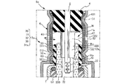
図5Eを参照して、本発明の第2の実施形態におけるガスセンサ8eについて説明する。上記実施形態においては、第2弾性部材60を撥水フィルタ61の内側に配設した構成を示したが、本実施形態においては、撥水フィルタ61eを第2弾性部材60eの内側に配設した点、及び、端子金具1eを用いた点が相違する。
なお、本実施形態においても、上述の端子金具1、1a、1b、1c、1dを適宜採用することができる。
なお、本実施形態においても、上述の端子金具1、1a、1b、1c、1dを適宜採用することができる。
本実施形態においては、ケーシング5とガスセンサ素子3の信号取出部33との間に、撥水フィルタ61eの先端部612eと第2弾性部材60eとを介装し、信号取出部33の外周面331を背にしてケーシング5の中径部51を径方向中心側に向かって圧縮して、かしめ部55を設けてある。
撥水フィルタ61eの先端部612eを第2弾性部材60eよりも、内側に配設することにより、かしめ部55を形成する際に、第2弾性部材60eを介して撥水フィルタ61eが圧縮されるので、過剰な変形が抑制され、撥水フィルタ61eと第2弾性部材60eとの間に間隙が形成されることがなく、確実に水滴の侵入を阻止できる。
撥水フィルタ61eの先端部612eを第2弾性部材60eよりも、内側に配設することにより、かしめ部55を形成する際に、第2弾性部材60eを介して撥水フィルタ61eが圧縮されるので、過剰な変形が抑制され、撥水フィルタ61eと第2弾性部材60eとの間に間隙が形成されることがなく、確実に水滴の侵入を阻止できる。
加えて、本実施形態においては、端子金具1eの導通部12の先端側に、連結部19を介して接続する第2の導通部18を設けて、固体電解質体300の内径を縮径した径変部323において基準電極層320に当接せしめてある。
本実施形態においては、撥水フィルタ61eのクリープ変形が抑制されるので、前記実施形態以上に水滴の侵入防止が図られている。さらに、グロメットの熱劣化を抑制して、導通信頼性の確保と耐久性の向上を図る効果に加え、第2の導通部18によって補完的に導通信頼性が向上されている。
第2の導通部18は、先端側で二股に分かれた舌片状に形成されており、傾斜した径変部323に当接することで軸方向と径方向とに押圧することになる。その結果、端子金具1eに外部からの振動が作用しても、基準電極層320を径方向に弾性的に押圧する導通部12と基準電極層320を軸方向にも径方向にも端正的に押圧する第2の導通部18とのいずれかが常に基準電極層320との導通を維持することになるので、極めて高い導通信頼性を発揮できる。
本実施形態においては、撥水フィルタ61eのクリープ変形が抑制されるので、前記実施形態以上に水滴の侵入防止が図られている。さらに、グロメットの熱劣化を抑制して、導通信頼性の確保と耐久性の向上を図る効果に加え、第2の導通部18によって補完的に導通信頼性が向上されている。
第2の導通部18は、先端側で二股に分かれた舌片状に形成されており、傾斜した径変部323に当接することで軸方向と径方向とに押圧することになる。その結果、端子金具1eに外部からの振動が作用しても、基準電極層320を径方向に弾性的に押圧する導通部12と基準電極層320を軸方向にも径方向にも端正的に押圧する第2の導通部18とのいずれかが常に基準電極層320との導通を維持することになるので、極めて高い導通信頼性を発揮できる。
図5Fを参照して、第2の実施形態におけるガスセンサの変形例8fについて説明する。
前記実施形態においては、端子金具1、1a~1eにおいて、信号線2を圧着する圧着部10を端子金具1の先端に設けた例を示したが、本実施形態においては、端子金具1fとして、信号線2の芯線20を圧着固定する圧着部10hが、端子金具1fの中心に配設され、連結部13fを介して、基端側に基端側当接部16を有する筒状部15が設けられ、先端側に連結部11fを介して、導通部12fが設けられている点が相違する。
なお、本変形例を一部の変形例を除き、他の実施形態と組み合わせることも可能である。
前記実施形態においては、端子金具1、1a~1eにおいて、信号線2を圧着する圧着部10を端子金具1の先端に設けた例を示したが、本実施形態においては、端子金具1fとして、信号線2の芯線20を圧着固定する圧着部10hが、端子金具1fの中心に配設され、連結部13fを介して、基端側に基端側当接部16を有する筒状部15が設けられ、先端側に連結部11fを介して、導通部12fが設けられている点が相違する。
なお、本変形例を一部の変形例を除き、他の実施形態と組み合わせることも可能である。
本実施形態においても、第2の実施形態におけるガスセンサ8eと同様に、加えて、ガスセンサ素子3の平面部34に端子金具1fの素子側当接部14が当接し、基端側当接部16が第1弾性部材4の底面40に当接し、ガスセンサ素子3の基端と第1弾性部材4との間に、撥水フィルタ61を介して通気孔52に連なる断熱空間322が形成されるので、第1弾性部材4の熱劣化が抑制され、端子金具1fの導通部12fと基準電極層321と間の導通信頼性に優れたガスセンサ8fを実現することができる。
加えて、本実施形態においては、圧着部10fがガスセンサ素子3の内側に収容されるので、ガスセンサ8fの体格を小さくすることができる。
さらに、圧着部10fが、導通部12fよりも基端側に設けられているため、圧着部10を先端に設けたガスセンサ8、8a~8e比べ、熱源から圧着部10fまでの距離が遠くなるので、信号線2の絶縁被覆への熱的ダメージを軽減できる。
加えて、本実施形態においては、圧着部10fがガスセンサ素子3の内側に収容されるので、ガスセンサ8fの体格を小さくすることができる。
さらに、圧着部10fが、導通部12fよりも基端側に設けられているため、圧着部10を先端に設けたガスセンサ8、8a~8e比べ、熱源から圧着部10fまでの距離が遠くなるので、信号線2の絶縁被覆への熱的ダメージを軽減できる。
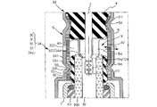
図5Gを参照して、第3の実施形態におけるガスセンサ8gについて説明する。本実施形態においては、信号線2との接続を図る圧着部10gを基端側に設けた端子金具1gを用いると共に、圧着部10gを内側に収容する筒状に形成した絶縁体66を設けた点が相違する。
本実施形態における端子金具1gでは、圧着部10gが筒状部15gよりも基端側に設けられている。
本実施形態によれば、圧着部10gが通気孔52よりも基端側に位置し、比較的低温の環境に配置されるので、信号線2の絶縁被覆への熱的ダメージを低減することもできる。
本実施形態における端子金具1gでは、圧着部10gが筒状部15gよりも基端側に設けられている。
本実施形態によれば、圧着部10gが通気孔52よりも基端側に位置し、比較的低温の環境に配置されるので、信号線2の絶縁被覆への熱的ダメージを低減することもできる。
絶縁体66は、アルミナ等の絶縁材料を用いて、圧着部10gを収容可能な空間を内側に設けて環状に形成し、筒状部15gと底面40との間に介装してある。
この場合、熱伝導率の高い絶縁体66が第1状弾性部材4の底面40に接することになるが、絶縁体66よりも先端側に、筒状部15gによって支持されつつ、通気孔52を介して大気に連通された断熱空間322が絶縁体66よりも先端側に存在するため、ガスセンサ素子3を加熱する被測定ガスの熱が第1弾性部材4に到達することがほとんどなく、第1弾性部材4の熱劣化を抑制することが可能となる。
この場合、熱伝導率の高い絶縁体66が第1状弾性部材4の底面40に接することになるが、絶縁体66よりも先端側に、筒状部15gによって支持されつつ、通気孔52を介して大気に連通された断熱空間322が絶縁体66よりも先端側に存在するため、ガスセンサ素子3を加熱する被測定ガスの熱が第1弾性部材4に到達することがほとんどなく、第1弾性部材4の熱劣化を抑制することが可能となる。
本実施形態においては、第1の実施形態と同様、第2弾性部材60を撥水フィルタ61の先端部612をよりも、内側に配設した例を示したが、第2の実施形態と同様、撥水フィルタ61eの先端部612eを第2弾性部材60eよりも内側に配設しても良い。
また、筒状の絶縁体66に代えて、第1弾性部材4の先端側に、圧着部10gを収容するための圧着部空間部を設けて第1弾性部材4の内側に収容するようにしても良い。
また、筒状の絶縁体66に代えて、第1弾性部材4の先端側に、圧着部10gを収容するための圧着部空間部を設けて第1弾性部材4の内側に収容するようにしても良い。
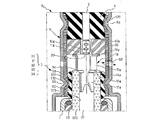
図5Hを参照して、第4の実施形態におけるガスセンサ8hについて説明する。本実施形態においては、端子金具1hを用いた点が相違する。
また、本実施形態では、第1の実施形態と同様、第2弾性部材60を撥水フィルタ61の先端部612をよりも、内側に配設した例を示したが、第2の実施形態と同様、撥水フィルタ61eの先端部612eを第2弾性部材60eよりも内側に配設しても良い。
本実施形態においても、前記実施形態と同様に、センサ内部への水滴の侵入を阻止し、耐久性に優れたガスセンサ8hを実現できる。
本実施形態におけるガスセンサ素子3hでは、固体電解質体300の内周表面321hに形成した基準電極層320hを、固体電解質体300の基端側に形成した信号取出部33hにおいて、固体電解質体300の外周面331hまで延設してある。
本実施形態においても、第1弾性部材4とガスセンサ素子3hとの間に断熱空間322を形成することで、第1弾性部材4の熱劣化が抑制されている。
また、本実施形態では、第1の実施形態と同様、第2弾性部材60を撥水フィルタ61の先端部612をよりも、内側に配設した例を示したが、第2の実施形態と同様、撥水フィルタ61eの先端部612eを第2弾性部材60eよりも内側に配設しても良い。
本実施形態においても、前記実施形態と同様に、センサ内部への水滴の侵入を阻止し、耐久性に優れたガスセンサ8hを実現できる。
本実施形態におけるガスセンサ素子3hでは、固体電解質体300の内周表面321hに形成した基準電極層320hを、固体電解質体300の基端側に形成した信号取出部33hにおいて、固体電解質体300の外周面331hまで延設してある。
本実施形態においても、第1弾性部材4とガスセンサ素子3hとの間に断熱空間322を形成することで、第1弾性部材4の熱劣化が抑制されている。
さらに、端子金具1hの筒状部15hの一部を、導通部12hとして、固体電解質体300の外周面331hに嵌着せしめてある。
導通部12hは、固体電解質体300の外周面331hの外径よりも僅かに小さい径で一部が切り欠かれた断面C字形に形成されており、導通部12hを外周面331hに嵌着したときに外側から中心に向かう方向の押圧力を生じるよう付勢されている。
導通部12hは、固体電解質体300の外周面331hの外径よりも僅かに小さい径で一部が切り欠かれた断面C字形に形成されており、導通部12hを外周面331hに嵌着したときに外側から中心に向かう方向の押圧力を生じるよう付勢されている。
これによって、導通部12hが外周側方向から基準電極層320hを弾性的に押圧して導通を図っている。
導通部を固体電解質体300の内周面321hに圧入する場合にくらべ、導通部12hの外径が大きくなることで、導通部12hの表面積が拡大され、冷却効果が向上し、第1弾性部材4への伝熱量の低減を図ることも可能となる。
導通部を固体電解質体300の内周面321hに圧入する場合にくらべ、導通部12hの外径が大きくなることで、導通部12hの表面積が拡大され、冷却効果が向上し、第1弾性部材4への伝熱量の低減を図ることも可能となる。
さらに、信号取出部33hの外周に設けた段差部を平面部34hとして、素子側当接部14hを当接せしめてあり、筒状部15hの基端側当接部16hが第1弾性部材4の底面40に当接し、軸方向にも第1弾性部材4から弾性的な押圧力が作用し、導通信頼性の向上を図っている。
さらに、導通部12hの外周を覆うように第2弾性部材60が嵌着され、撥水フィルタ61と共にかしめ部55によって外周方向から圧縮されている。
導通部12hは、信号取出部33hの外周面331hに延設した基準電極層320hを中心に向かって、弾性的に押圧するように付勢されているが、第2弾性部材60が重畳的に導通部12hを中心に向かって弾性的に押圧するので、より一相導通信頼性を向上させることができる。
さらに、導通部12hの外周を覆うように第2弾性部材60が嵌着され、撥水フィルタ61と共にかしめ部55によって外周方向から圧縮されている。
導通部12hは、信号取出部33hの外周面331hに延設した基準電極層320hを中心に向かって、弾性的に押圧するように付勢されているが、第2弾性部材60が重畳的に導通部12hを中心に向かって弾性的に押圧するので、より一相導通信頼性を向上させることができる。
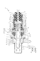
図6を参照して、第5の実施形態におけるガスセンサ8iについて説明する。前記実施形態においては、ケーシング5をハウジング7に溶接固定した例を示したが、本実施形態においては、ケーシング5iの先端に外周方向に張り出す鍔部56iを設けて、粉末充填部材62i、絶縁性封止部材63i、シール部材64と共に、ハウジング7iの粉末充填部係止部72とかしめ部73iとの間に挟持し、軸方向の軸力を負荷して、加締め固定した点が相違する。
本実施形態におけるケーシング5iの中径部51の先端には、径方向に向かってハット型に広がる鍔部56iが設けられている。鍔部56iは、シール部材64と共に、ハウジング7iのかしめ部73iによってかしめ固定されている。
また、図6には、第1の実施形態におけるガスセンサ8に用いた端子金具1と同じ構成の端子金具1を用いた例を示してあるが、上述の端子金具1a~1hのいずれも適宜採用することができる。本実施形態においても、前記実施形態と同様の効果を発揮できる。
本実施形態におけるケーシング5iの中径部51の先端には、径方向に向かってハット型に広がる鍔部56iが設けられている。鍔部56iは、シール部材64と共に、ハウジング7iのかしめ部73iによってかしめ固定されている。
また、図6には、第1の実施形態におけるガスセンサ8に用いた端子金具1と同じ構成の端子金具1を用いた例を示してあるが、上述の端子金具1a~1hのいずれも適宜採用することができる。本実施形態においても、前記実施形態と同様の効果を発揮できる。
図7Aを参照して、第6の実施形態におけるガスセンサ8jについて説明する。前記実施形態においては、いわゆるヒータレスタイプのガスセンサを示したが、本発明は、本実施形態に示すように、軸状のヒータHを内蔵するガスセンサ8iにも適用できる。
なお、前記実施形態における各変形例を適宜採用することもできる。
本実施形態におけるガスセンサ8jは、ガスセンサ素子3jと、ガスセンサ素子3jの内側に設けられ、通電により発熱する発熱体を内蔵するヒータHと、ヒータHの基端に設けた一対の通電電極ELHに接続する一対の通電端子金具1Hと、通電端子金具1Hを介して外部に接続する一対の通電線2Hと、ガスセンサ素子3jに設けた基準電極層320に接続するプラス端子金具1Pと、プラス端子金具1Pを介して外部に接続するプラス信号線2Pと、測定電極層310に接続するマイナス端子金具1Nと、マイナス端子金具1Nを介して外部に接続するマイナス信号線2Nと、ガスセンサ素子3jの基端側を覆うケーシング5jと、一対の通電線2Hとプラス信号線2Pとマイナス信号線2Nとを保持しつつ、ケーシング5jの基端側を封止する第1弾性部材4jと、ケーシング5jに穿設した通気孔52に対向して設けられた筒状の撥水フィルタ61jと、第2弾性部材60jと、ハウジング7jとによって構成されている。
なお、前記実施形態における各変形例を適宜採用することもできる。
本実施形態におけるガスセンサ8jは、ガスセンサ素子3jと、ガスセンサ素子3jの内側に設けられ、通電により発熱する発熱体を内蔵するヒータHと、ヒータHの基端に設けた一対の通電電極ELHに接続する一対の通電端子金具1Hと、通電端子金具1Hを介して外部に接続する一対の通電線2Hと、ガスセンサ素子3jに設けた基準電極層320に接続するプラス端子金具1Pと、プラス端子金具1Pを介して外部に接続するプラス信号線2Pと、測定電極層310に接続するマイナス端子金具1Nと、マイナス端子金具1Nを介して外部に接続するマイナス信号線2Nと、ガスセンサ素子3jの基端側を覆うケーシング5jと、一対の通電線2Hとプラス信号線2Pとマイナス信号線2Nとを保持しつつ、ケーシング5jの基端側を封止する第1弾性部材4jと、ケーシング5jに穿設した通気孔52に対向して設けられた筒状の撥水フィルタ61jと、第2弾性部材60jと、ハウジング7jとによって構成されている。
本実施形態においても、前記実施形態と同様に、絶縁体66jを背にして、第1弾性部材4jの先端側に設けた筒状部41jと撥水フィルタ61jの基端側とをケーシング5jの基端側かしめ部57で加締め、第2弾性部材60jと撥水フィルタ61jとをガスセンサ素子3jの信号取出部33jを背にして、ケーシング5の先端側かしめ部55によってかしめることで、撥水フィルタ61jの両端の気密性を維持し、外部からの水滴の侵入を阻止することができる。
また、本実施形態においては、測定電極層310に接続するマイナス端子金具1Nの導通部12Nをガスセンサ素子3jの基端側から突出させて、断熱空間形成用筒状部15jとし、基端側当接部16jを絶縁体66jの底面に当接させて、断熱空間322jを形成している。
また、本実施形態においては、測定電極層310に接続するマイナス端子金具1Nの導通部12Nをガスセンサ素子3jの基端側から突出させて、断熱空間形成用筒状部15jとし、基端側当接部16jを絶縁体66jの底面に当接させて、断熱空間322jを形成している。
図7Bを参照して、第6の実施形態におけるガスセンサの変形例8kについて説明する。本実施形態では、ケーシング5kの先端に外周方向に張り出す鍔部56kを設けて、粉末充填部材62k、絶縁性封止部材63k、シール部材64と共に、ハウジング7kの粉末充填部係止部72とかしめ部73kとの間に挟持し、軸方向の軸力を負荷して、加締め固定した点が相違する。
また、前記実施形態における変形例を適宜採用することもできる。本実施形態においても、前記実施形態と同様の効果を発揮できる。
また、前記実施形態における変形例を適宜採用することもできる。本実施形態においても、前記実施形態と同様の効果を発揮できる。
尚、本発明は、前記実施形態に限定するものではなく、本発明の趣旨を逸脱しない範囲で適宜変更可能である。
例えば、前記実施形態においては、濃度検出素子として酸素イオン導電性の固体電解質体の内外面に電極層を形成した酸素濃度センサの場合について説明したが、本発明は、測定部に複数の電極層と固体電解質体を形成したNOxセンサや、固体電解質体としてプロトン伝導体を用いたアンモニアセンサ等においても適宜採用し得るものである。
例えば、前記実施形態においては、濃度検出素子として酸素イオン導電性の固体電解質体の内外面に電極層を形成した酸素濃度センサの場合について説明したが、本発明は、測定部に複数の電極層と固体電解質体を形成したNOxセンサや、固体電解質体としてプロトン伝導体を用いたアンモニアセンサ等においても適宜採用し得るものである。
1 端子金具
2 信号線
3 ガスセンサ素子
30 検出部
300 固体電解質体
301 該固体電解質体外周表面
310 測定電極層
32 基準ガス室
320 基準電極層
321 固体電解質体内周表面
33 ガスセンサ素子信号取出部
331 信号取出部外周面
4 第1の筒状弾性部材(第1弾性部材)
5 ケーシング
52 通気孔
54 基端側かしめ部
55 先端側かしめ部
60 第2の筒状弾性部材(第2弾性部材)
61 撥水フィルタ
611 撥水フィルタ基端部
612 撥水フィルタ先端部
7 ハウジング
91 被測定ガス
2 信号線
3 ガスセンサ素子
30 検出部
300 固体電解質体
301 該固体電解質体外周表面
310 測定電極層
32 基準ガス室
320 基準電極層
321 固体電解質体内周表面
33 ガスセンサ素子信号取出部
331 信号取出部外周面
4 第1の筒状弾性部材(第1弾性部材)
5 ケーシング
52 通気孔
54 基端側かしめ部
55 先端側かしめ部
60 第2の筒状弾性部材(第2弾性部材)
61 撥水フィルタ
611 撥水フィルタ基端部
612 撥水フィルタ先端部
7 ハウジング
91 被測定ガス
Claims (5)
- 少なくとも、特定イオンに対して伝導性を有する有底筒状の固体電解質体(300)と、
該固体電解質体の外周表面(301)に形成され、被測定ガス(91)に接する測定電極層(310)と、前記固体電解質体の内周表面(321)に形成され、基準ガスとして導入した大気に接する基準電極層(320)とからなる検出部(30)を具備して、被測定ガス中の特定成分を検出するガスセンサ素子(3、3a、3c、3d、3e、3h)と、
該ガスセンサ素子と外部との接続を図る信号線(2、2P、2H、2N)と、
前記ガスセンサ素子と前記信号線との接続を図る端子金具(1、1a~1i、1P、1N)と、
前記ガスセンサ素子を収容し、前記検出部を被測定ガス(91)中に配設・固定するハウジング(7、7j、7k)と、
前記ガスセンサ素子の基端側を前記端子金具と共に覆いつつ、内側に大気を導入する通気孔(52)を備えた筒状のケーシング(5、5k)と、
該ケーシングの基端側を封止しつつ、前記端子金具に接続された前記信号線を保持する第1の筒状弾性部材(4,4j、4k)と、
前記通気孔に対向して設けられ、気体の透過は許容し液体の透過は阻止する多孔質繊維構造体を筒状に形成した撥水フィルタ(61、61e)と、を具備し、被測定ガス中の特定成分を検出するガスセンサであって、
前記撥水フィルタの基端部(611、611e)は、前記第1の筒状弾性部材と、前記信号線と共に、前記ケーシングの基端側を圧縮変形した基端側かしめ部(54)によって封止し、
前記ケーシング(5、5k)と前記ガスセンサ素子の信号取出部(33、33h、33k)との間に、前記ケーシング及び前記撥水フィルタを弾性的に押圧する第2の筒状弾性部材(60、60e)を設け、
前記撥水フィルタの先端部(612、612e)は、前記第2の筒状弾性部材と共に、前記信号取出部の外周面(331、331h、331k)を背にして、前記ケーシングの先端側を圧縮変形した先端側かしめ部(55、55e)によって封止したことを特徴とするガスセンサ(8、8a~8k)。 - 前記第2の筒状弾性部材を前記撥水フィルタと前記信号取出部の外周面との間に設けた請求項1に記載のガスセンサ。
- 前記撥水フィルタを前記第2の筒状弾性部材と前記信号取出部の外周面との間に設けた請求項1に記載のガスセンサ。
- 前記第1の筒状弾性部材及び前記第2の筒状弾性部材が、フッ素ゴム、シリコーンゴム、ウレタンゴムのいずれかから選択した耐熱性弾性部材からなる請求項1ないし3のいずれか記載のガスセンサ。
- 前記端子金具の一部が、前記信号取出部から突出して、前記第1の筒状弾性部材の底面に当接して、前記ガスセンサ素子と前記第1の筒状弾性部材との間に前記通気孔に連通する断熱空間を具備する請求項1ないし4のいずれか記載のガスセンサ。
Priority Applications (1)
| Application Number | Priority Date | Filing Date | Title |
|---|---|---|---|
| CN201480063519.2A CN105745533B (zh) | 2013-11-20 | 2014-11-17 | 气体传感器 |
Applications Claiming Priority (2)
| Application Number | Priority Date | Filing Date | Title |
|---|---|---|---|
| JP2013-239477 | 2013-11-20 | ||
| JP2013239477A JP6146271B2 (ja) | 2013-11-20 | 2013-11-20 | ガスセンサ |
Publications (1)
| Publication Number | Publication Date |
|---|---|
| WO2015076223A1 true WO2015076223A1 (ja) | 2015-05-28 |
Family
ID=53179486
Family Applications (1)
| Application Number | Title | Priority Date | Filing Date |
|---|---|---|---|
| PCT/JP2014/080381 Ceased WO2015076223A1 (ja) | 2013-11-20 | 2014-11-17 | ガスセンサ |
Country Status (3)
| Country | Link |
|---|---|
| JP (1) | JP6146271B2 (ja) |
| CN (1) | CN105745533B (ja) |
| WO (1) | WO2015076223A1 (ja) |
Cited By (3)
| Publication number | Priority date | Publication date | Assignee | Title |
|---|---|---|---|---|
| CN111084608A (zh) * | 2018-10-23 | 2020-05-01 | 成都西达瑞电子科技有限公司 | 一种透气性能良好的无线传感器 |
| JP2021162414A (ja) * | 2020-03-31 | 2021-10-11 | 日本碍子株式会社 | ガスセンサ |
| CN113826005A (zh) * | 2019-05-16 | 2021-12-21 | 株式会社电装 | 气体传感器 |
Families Citing this family (5)
| Publication number | Priority date | Publication date | Assignee | Title |
|---|---|---|---|---|
| JP2017067505A (ja) * | 2015-09-28 | 2017-04-06 | 株式会社デンソー | 車載用センサ |
| CN106369246B (zh) * | 2016-10-18 | 2018-12-25 | 北京空间技术研制试验中心 | 气动测量传感器热密封方法 |
| JP2022147914A (ja) * | 2021-03-24 | 2022-10-06 | 日本碍子株式会社 | ガスセンサ |
| JP2022147913A (ja) * | 2021-03-24 | 2022-10-06 | 日本碍子株式会社 | ガスセンサ |
| JP2024118014A (ja) * | 2023-02-20 | 2024-08-30 | 日本碍子株式会社 | ガスセンサ |
Citations (4)
| Publication number | Priority date | Publication date | Assignee | Title |
|---|---|---|---|---|
| JP2003232768A (ja) * | 2002-02-08 | 2003-08-22 | Hitachi Unisia Automotive Ltd | 酸素センサ |
| JP2009075066A (ja) * | 2007-08-24 | 2009-04-09 | Denso Corp | ガスセンサ |
| JP2010223750A (ja) * | 2009-03-24 | 2010-10-07 | Denso Corp | ガスセンサ及びその製造方法 |
| WO2013073170A1 (ja) * | 2011-11-16 | 2013-05-23 | 日本特殊陶業株式会社 | ガスセンサ |
Family Cites Families (7)
| Publication number | Priority date | Publication date | Assignee | Title |
|---|---|---|---|---|
| CN1020993C (zh) * | 1985-04-01 | 1993-05-26 | 中国科学院长春应用化学研究所 | 薄型防水气体扩散电极的制造方法 |
| US5423972A (en) * | 1994-01-18 | 1995-06-13 | General Motors Corporation | Watertight exhaust gas sensor |
| CN1959396A (zh) * | 2005-11-04 | 2007-05-09 | 株式会社电装 | 气体传感器 |
| JP4833717B2 (ja) * | 2006-03-31 | 2011-12-07 | シチズンホールディングス株式会社 | 接触燃焼式ガスセンサとその検知素子および補償素子 |
| JP5139128B2 (ja) * | 2007-04-23 | 2013-02-06 | 日本特殊陶業株式会社 | ガスセンサおよびその製造方法ならびにその製造用治具 |
| US20090050481A1 (en) * | 2007-08-24 | 2009-02-26 | Denso Corporation | Gas sensor with increased durability and reliability |
| JP4886006B2 (ja) * | 2009-05-11 | 2012-02-29 | 日本特殊陶業株式会社 | ガスセンサユニット |
-
2013
- 2013-11-20 JP JP2013239477A patent/JP6146271B2/ja not_active Expired - Fee Related
-
2014
- 2014-11-17 CN CN201480063519.2A patent/CN105745533B/zh not_active Expired - Fee Related
- 2014-11-17 WO PCT/JP2014/080381 patent/WO2015076223A1/ja not_active Ceased
Patent Citations (4)
| Publication number | Priority date | Publication date | Assignee | Title |
|---|---|---|---|---|
| JP2003232768A (ja) * | 2002-02-08 | 2003-08-22 | Hitachi Unisia Automotive Ltd | 酸素センサ |
| JP2009075066A (ja) * | 2007-08-24 | 2009-04-09 | Denso Corp | ガスセンサ |
| JP2010223750A (ja) * | 2009-03-24 | 2010-10-07 | Denso Corp | ガスセンサ及びその製造方法 |
| WO2013073170A1 (ja) * | 2011-11-16 | 2013-05-23 | 日本特殊陶業株式会社 | ガスセンサ |
Cited By (4)
| Publication number | Priority date | Publication date | Assignee | Title |
|---|---|---|---|---|
| CN111084608A (zh) * | 2018-10-23 | 2020-05-01 | 成都西达瑞电子科技有限公司 | 一种透气性能良好的无线传感器 |
| CN113826005A (zh) * | 2019-05-16 | 2021-12-21 | 株式会社电装 | 气体传感器 |
| JP2021162414A (ja) * | 2020-03-31 | 2021-10-11 | 日本碍子株式会社 | ガスセンサ |
| JP7372870B2 (ja) | 2020-03-31 | 2023-11-01 | 日本碍子株式会社 | ガスセンサ |
Also Published As
| Publication number | Publication date |
|---|---|
| CN105745533A (zh) | 2016-07-06 |
| JP6146271B2 (ja) | 2017-06-14 |
| JP2015099109A (ja) | 2015-05-28 |
| CN105745533B (zh) | 2018-10-26 |
Similar Documents
| Publication | Publication Date | Title |
|---|---|---|
| JP6146271B2 (ja) | ガスセンサ | |
| JP5592336B2 (ja) | ガスセンサ | |
| JP4955591B2 (ja) | ガスセンサ | |
| JP5310170B2 (ja) | ガスセンサ及びその製造方法 | |
| US20090050481A1 (en) | Gas sensor with increased durability and reliability | |
| JP4363492B2 (ja) | ガスセンサ | |
| JP6287098B2 (ja) | ガスセンサ | |
| JP5209687B2 (ja) | ガスセンサ | |
| US8042380B2 (en) | Gas sensor | |
| JP2013019885A (ja) | ガスセンサ | |
| US7484401B2 (en) | Gas sensor | |
| JP2003194764A (ja) | ガスセンサ | |
| JP4934072B2 (ja) | ガスセンサ | |
| JP4390841B2 (ja) | 酸素センサ | |
| EP1793223B1 (en) | Gas sensor | |
| JP4817419B2 (ja) | ガスセンサ | |
| JP2007155517A (ja) | ガスセンサ | |
| JP5214665B2 (ja) | ガスセンサ | |
| US20170212074A1 (en) | Gas sensor | |
| JP5931701B2 (ja) | ガスセンサ | |
| JP3607817B2 (ja) | ガスセンサ | |
| JP2007271516A (ja) | ガスセンサ | |
| JP2001153833A (ja) | 酸素センサ | |
| JP2000046788A (ja) | ガスセンサ | |
| JP2013002879A (ja) | ガスセンサユニット |
Legal Events
| Date | Code | Title | Description |
|---|---|---|---|
| 121 | Ep: the epo has been informed by wipo that ep was designated in this application |
Ref document number: 14863307 Country of ref document: EP Kind code of ref document: A1 |
|
| DPE1 | Request for preliminary examination filed after expiration of 19th month from priority date (pct application filed from 20040101) | ||
| NENP | Non-entry into the national phase |
Ref country code: DE |
|
| WWE | Wipo information: entry into national phase |
Ref document number: IDP00201604006 Country of ref document: ID |
|
| 122 | Ep: pct application non-entry in european phase |
Ref document number: 14863307 Country of ref document: EP Kind code of ref document: A1 |