WO2015075872A1 - ヒートポンプシステム - Google Patents
ヒートポンプシステム Download PDFInfo
- Publication number
- WO2015075872A1 WO2015075872A1 PCT/JP2014/005501 JP2014005501W WO2015075872A1 WO 2015075872 A1 WO2015075872 A1 WO 2015075872A1 JP 2014005501 W JP2014005501 W JP 2014005501W WO 2015075872 A1 WO2015075872 A1 WO 2015075872A1
- Authority
- WO
- WIPO (PCT)
- Prior art keywords
- heat
- refrigerant
- heat exchanger
- heating
- heat medium
- Prior art date
- Legal status (The legal status is an assumption and is not a legal conclusion. Google has not performed a legal analysis and makes no representation as to the accuracy of the status listed.)
- Ceased
Links
Images


Classifications
-
- B—PERFORMING OPERATIONS; TRANSPORTING
- B60—VEHICLES IN GENERAL
- B60H—ARRANGEMENTS OF HEATING, COOLING, VENTILATING OR OTHER AIR-TREATING DEVICES SPECIALLY ADAPTED FOR PASSENGER OR GOODS SPACES OF VEHICLES
- B60H1/00—Heating, cooling or ventilating [HVAC] devices
- B60H1/00642—Control systems or circuits; Control members or indication devices for heating, cooling or ventilating devices
- B60H1/00814—Control systems or circuits characterised by their output, for controlling particular components of the heating, cooling or ventilating installation
- B60H1/00878—Control systems or circuits characterised by their output, for controlling particular components of the heating, cooling or ventilating installation the components being temperature regulating devices
- B60H1/00899—Controlling the flow of liquid in a heat pump system
- B60H1/00921—Controlling the flow of liquid in a heat pump system where the flow direction of the refrigerant does not change and there is an extra subcondenser, e.g. in an air duct
-
- B—PERFORMING OPERATIONS; TRANSPORTING
- B60—VEHICLES IN GENERAL
- B60H—ARRANGEMENTS OF HEATING, COOLING, VENTILATING OR OTHER AIR-TREATING DEVICES SPECIALLY ADAPTED FOR PASSENGER OR GOODS SPACES OF VEHICLES
- B60H1/00—Heating, cooling or ventilating [HVAC] devices
- B60H1/32—Cooling devices
- B60H1/3204—Cooling devices using compression
- B60H1/3228—Cooling devices using compression characterised by refrigerant circuit configurations
- B60H1/32281—Cooling devices using compression characterised by refrigerant circuit configurations comprising a single secondary circuit, e.g. at evaporator or condenser side
-
- F—MECHANICAL ENGINEERING; LIGHTING; HEATING; WEAPONS; BLASTING
- F25—REFRIGERATION OR COOLING; COMBINED HEATING AND REFRIGERATION SYSTEMS; HEAT PUMP SYSTEMS; MANUFACTURE OR STORAGE OF ICE; LIQUEFACTION SOLIDIFICATION OF GASES
- F25B—REFRIGERATION MACHINES, PLANTS OR SYSTEMS; COMBINED HEATING AND REFRIGERATION SYSTEMS; HEAT PUMP SYSTEMS
- F25B47/00—Arrangements for preventing or removing deposits or corrosion, not provided for in another subclass
- F25B47/02—Defrosting cycles
-
- F—MECHANICAL ENGINEERING; LIGHTING; HEATING; WEAPONS; BLASTING
- F25—REFRIGERATION OR COOLING; COMBINED HEATING AND REFRIGERATION SYSTEMS; HEAT PUMP SYSTEMS; MANUFACTURE OR STORAGE OF ICE; LIQUEFACTION SOLIDIFICATION OF GASES
- F25B—REFRIGERATION MACHINES, PLANTS OR SYSTEMS; COMBINED HEATING AND REFRIGERATION SYSTEMS; HEAT PUMP SYSTEMS
- F25B49/00—Arrangement or mounting of control or safety devices
- F25B49/02—Arrangement or mounting of control or safety devices for compression type machines, plants or systems
-
- B—PERFORMING OPERATIONS; TRANSPORTING
- B60—VEHICLES IN GENERAL
- B60H—ARRANGEMENTS OF HEATING, COOLING, VENTILATING OR OTHER AIR-TREATING DEVICES SPECIALLY ADAPTED FOR PASSENGER OR GOODS SPACES OF VEHICLES
- B60H1/00—Heating, cooling or ventilating [HVAC] devices
- B60H1/00642—Control systems or circuits; Control members or indication devices for heating, cooling or ventilating devices
- B60H1/00814—Control systems or circuits characterised by their output, for controlling particular components of the heating, cooling or ventilating installation
- B60H1/00878—Control systems or circuits characterised by their output, for controlling particular components of the heating, cooling or ventilating installation the components being temperature regulating devices
- B60H2001/00961—Control systems or circuits characterised by their output, for controlling particular components of the heating, cooling or ventilating installation the components being temperature regulating devices comprising means for defrosting outside heat exchangers
-
- F—MECHANICAL ENGINEERING; LIGHTING; HEATING; WEAPONS; BLASTING
- F25—REFRIGERATION OR COOLING; COMBINED HEATING AND REFRIGERATION SYSTEMS; HEAT PUMP SYSTEMS; MANUFACTURE OR STORAGE OF ICE; LIQUEFACTION SOLIDIFICATION OF GASES
- F25B—REFRIGERATION MACHINES, PLANTS OR SYSTEMS; COMBINED HEATING AND REFRIGERATION SYSTEMS; HEAT PUMP SYSTEMS
- F25B2347/00—Details for preventing or removing deposits or corrosion
- F25B2347/02—Details of defrosting cycles
-
- F—MECHANICAL ENGINEERING; LIGHTING; HEATING; WEAPONS; BLASTING
- F25—REFRIGERATION OR COOLING; COMBINED HEATING AND REFRIGERATION SYSTEMS; HEAT PUMP SYSTEMS; MANUFACTURE OR STORAGE OF ICE; LIQUEFACTION SOLIDIFICATION OF GASES
- F25B—REFRIGERATION MACHINES, PLANTS OR SYSTEMS; COMBINED HEATING AND REFRIGERATION SYSTEMS; HEAT PUMP SYSTEMS
- F25B2400/00—General features or devices for refrigeration machines, plants or systems, combined heating and refrigeration systems or heat-pump systems, i.e. not limited to a particular subgroup of F25B
- F25B2400/05—Compression system with heat exchange between particular parts of the system
Definitions
- the present disclosure relates to a heat pump system that heats a fluid to be heated by a heat pump cycle.
- a heat pump system for heating a fluid to be heated by a heat pump cycle (vapor compression refrigeration cycle) is known.
- a heat pump cycle applied to this type of system when the refrigerant evaporation temperature in the outdoor heat exchanger functioning as an evaporator that exchanges heat with the outside air to evaporate falls to 0 ° C. or lower, it reaches the outdoor heat exchanger. Frost may occur.
- defrosting is performed by flowing high-temperature and high-pressure refrigerant (hot gas) discharged from the compressor of the heat pump cycle into the outdoor heat exchanger.
- hot gas defrosting So-called hot gas defrosting is also known.
- the defrosting time becomes relatively long, and the energy consumed by the compressor for defrosting increases.
- Patent Document 1 is a heat pump system applied to an air conditioner for a vehicle, in which outdoor heat in which frost is generated using waste heat stored in cooling water for cooling an in-vehicle electric device as a heat source. What performs defrosting of the exchanger is disclosed.
- the defrost of an outdoor heat exchanger since the defrost of an outdoor heat exchanger is performed using the waste heat of a vehicle-mounted electric equipment, it will increase that the energy which a compressor consumes for defrost is increased. Can be suppressed.
- the present disclosure can realize defrosting or suppressing frosting of the outdoor heat exchanger without increasing the energy consumption of the compressor of the heat pump cycle, regardless of the heat supplied from the outside.
- An object of the present invention is to provide a simple heat pump system.
- a heat pump system includes a heat pump cycle, a heat medium circulation circuit, and a heat medium heat dissipation unit.
- the heat pump cycle is a compressor that compresses and discharges refrigerant, a heat medium-refrigerant heat exchanger that exchanges heat between the high-pressure refrigerant discharged from the compressor and the heat medium, and refrigerant that flows out of the heat medium-refrigerant heat exchanger.
- a decompression device for decompressing and an outdoor heat exchanger for exchanging heat between the refrigerant decompressed by the decompression device and the outside air are provided.
- the heating medium circulation circuit includes a heating heat exchanger that circulates the heating medium and heats the heating target fluid by exchanging heat between the heating medium flowing out of the heating medium-refrigerant heat exchanger and the heating target fluid.
- a heating heat exchanger that circulates the heating medium and heats the heating target fluid by exchanging heat between the heating medium flowing out of the heating medium-refrigerant heat exchanger and the heating target fluid.
- the heat of the heat medium flowing out from the heat exchanger for heating is radiated to the low-pressure refrigerant flowing through the range from the decompression device outlet side to the compressor suction port.
- the heat medium heat radiating section since the heat medium heat radiating section is provided, the heat of the heat medium circulating in the heat medium circulation circuit can be radiated to the low-pressure refrigerant. And it can defrost an outdoor heat exchanger and the frost formation of an outdoor heat exchanger with the heat radiated from the heat medium to the low-pressure refrigerant.
- the heat of the heat medium flowing out from the heat exchanger for heating is radiated to the low-pressure refrigerant, so that the heat of the heat medium heated in the heat medium-refrigerant heat exchanger is heated. It can be preferentially used for heating, and the excess heat can be used for defrosting or suppressing frost formation in the outdoor heat exchanger. Therefore, it is possible to realize defrosting or suppressing frosting of the outdoor heat exchanger without increasing the energy consumption of the compressor.
- a heat pump system capable of realizing defrosting or suppressing frosting of the outdoor heat exchanger without depending on the heat supplied from an external heat source or the like and without increasing the energy consumption of the compressor of the heat pump cycle. Can be provided.
- the heat medium heat radiating unit is composed of a heat medium heat radiating heat exchanger that exchanges heat between the heat medium flowing out from the heating heat exchanger and the outside air, and the heat medium radiating heat exchanger and the outdoor heat exchange.
- the vessel may be integrated so as to enable heat transfer between the heat medium flowing through the heat exchanger for heat medium heat dissipation and the refrigerant flowing through the outdoor heat exchanger.
- circulates the heat exchanger for heat-medium heat dissipation can be directly transferred to an outdoor heat exchanger, and effective defrosting of an outdoor heat exchanger or effective Suppressing frost formation can be realized.
- the heat medium heat radiating section is composed of a heat medium heat radiating heat exchanger that exchanges heat between the heat medium flowing out from the heating heat exchanger and the outside air
- the outdoor heat exchanger is a heat medium radiating heat You may arrange
- circulates the heat exchanger for heat-medium heat radiation can be indirectly transferred to an outdoor heat exchanger via outside air, and defrosting or attachment of an outdoor heat exchanger is possible. Suppression of frost can be easily realized.
- the heat medium heat radiating section may be configured by a heat medium heat radiating heat exchanger that exchanges heat between the heat medium flowing out from the heating heat exchanger and the low-pressure refrigerant.
- the heat of the heat medium flowing through the heat exchanger for radiating the heat medium can be absorbed by the low-pressure refrigerant, the refrigerant evaporating temperature in the outdoor heat exchanger is raised and frost formation is suppressed. can do.
- a heat medium flow adjustment device for adjusting the flow rate of the heat medium flowing out from the heat exchanger for heating and flowing into the heat exchanger for heat medium heat dissipation is provided. It may be.
- the amount of heat radiated from the heat medium to the low-pressure refrigerant can be appropriately adjusted according to the heating capacity of the heating target fluid required for the heat pump cycle.
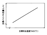
- FIG. 3 is a cross-sectional view taken along the line III-III in FIG. It is a control characteristic figure which shows the relationship between target blowing temperature TAO and bypass flow volume.
- TAO target blowing temperature
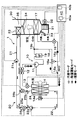
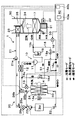
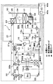
- It is a typical whole block diagram of the heat pump system of 2nd Embodiment. It is a typical whole block diagram of the heat pump system of 3rd Embodiment. It is a typical whole block diagram of the heat pump system of 4th Embodiment. It is a typical whole block diagram of the heat pump system of 5th Embodiment.
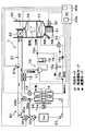
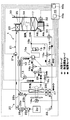
- the heat pump system 1 is applied to a vehicle air conditioner for a so-called hybrid vehicle that obtains a driving force for vehicle traveling from an internal combustion engine (engine) and a traveling electric motor.
- the heat pump system 1 of the present embodiment fulfills the function of heating or cooling the blown air blown into the vehicle interior, which is the air conditioning target space, in the vehicle air conditioner.
- the heat pump system 1 of the present embodiment circulates a heat pump cycle 10 that is a vapor compression refrigeration cycle that heats or cools blown air, and cooling water (for example, an ethylene glycol aqueous solution) that is a heat medium.
- the heat medium circulation circuit 20 is provided. And when blowing air is heated, cooling water is heated with the heat pump cycle 10, and blowing air is heated by using the heated cooling water as a heat source. Therefore, the fluid to be heated in the heat pump system 1 of the present embodiment is blown air.
- the heat pump cycle 10 of the present embodiment includes a cooling mode refrigerant circuit that cools the blown air to cool the vehicle interior, a heating mode refrigerant circuit that heats the blown air and heats the vehicle interior, It is configured to be switchable to a refrigerant circuit in a dehumidifying and heating mode in which heating is performed while dehumidifying the vehicle interior by heating the dehumidified blown air.
- the refrigerant flow in the cooling mode refrigerant circuit is indicated by a white arrow
- the refrigerant flow in the heating mode refrigerant circuit is indicated by a solid arrow
- the refrigerant flow in the dehumidifying heating mode refrigerant circuit is hatched. Shown with hatched arrows.
- the heat pump cycle 10 employs an HFC refrigerant (specifically, R134a) as the refrigerant, and a vapor compression subcritical refrigeration cycle in which the high-pressure side refrigerant pressure Pd of the cycle does not exceed the critical pressure of the refrigerant.
- HFC refrigerant specifically, R134a
- coolants for example, R1234yf
- refrigeration oil for lubricating the compressor 11 is mixed in the refrigerant, and a part of the refrigeration oil circulates in the cycle together with the refrigerant.
- the compressor 11 is disposed in the engine room, and sucks the refrigerant in the heat pump cycle 10 and discharges it until it becomes a high-pressure refrigerant.
- the compressor 11 of the present embodiment is an electric compressor configured by housing a fixed capacity type compression mechanism and an electric motor that drives the compression mechanism in one housing.
- various compression mechanisms such as a scroll-type compression mechanism and a vane-type compression mechanism can be employed. Further, the operation (rotation speed) of the electric motor is controlled by a control signal output from the air conditioning control device 40 described later, and either an AC motor or a DC motor may be adopted.
- the refrigerant inlet side of the refrigerant passage of the high temperature side water-refrigerant heat exchanger 12 is connected to the discharge port side of the compressor 11.
- the high-temperature side water-refrigerant heat exchanger 12 heat-exchanges the high-pressure refrigerant discharged from the compressor 11 and the cooling water circulating in the heat medium circulation circuit 20 to heat the cooling water. It is.
- a plurality of tubes through which high-pressure refrigerant is circulated are provided as high-pressure refrigerant passages, and water passages through which cooling water is circulated between adjacent tubes are formed.
- a heat exchanger or the like configured by disposing inner fins that promote heat exchange between the refrigerant and the cooling water in the passage can be employed.
- the inlet side of the heating expansion valve 13 is connected to the outlet side of the refrigerant passage of the high temperature side water-refrigerant heat exchanger 12.
- the heating expansion valve 13 is a pressure reducing device that depressurizes the high-pressure refrigerant that has flowed out of the high-temperature side water-refrigerant heat exchanger 12 at least in the heating mode, and includes a valve body configured to be able to change the throttle opening,
- This is an electric variable throttle mechanism that includes an electric actuator including a stepping motor that changes the throttle opening by displacing the body.
- the heating expansion valve 13 of the present embodiment is configured by a variable throttle mechanism with a full-open function that functions as a simple refrigerant passage without exerting almost any refrigerant decompression action by fully opening the throttle opening.
- the operation of the heating expansion valve 13 is controlled by a control signal output from the air conditioning control device 40.
- the refrigerant inlet side of the outdoor heat exchanger 14 is connected to the outlet side of the heating expansion valve 13.
- the outdoor heat exchanger 14 is a heat exchanger that is disposed on the front side in the engine room and exchanges heat between the refrigerant on the downstream side of the high-temperature side water-refrigerant heat exchanger 12 and the outside air blown from the blower fan 14a. .
- the outdoor heat exchanger 14 functions as a radiator that radiates high-pressure refrigerant at least in the cooling mode, and at least in the heating mode, the outdoor heat exchanger 14 receives the low-pressure refrigerant decompressed by the heating expansion valve 13 that is a decompression device. It functions as an evaporator that evaporates and exerts an endothermic effect.
- the blower fan 14a is an electric blower in which the operating rate, that is, the rotation speed (blowing capacity) is controlled by the control voltage output from the air conditioning control device 40.
- the outdoor heat exchanger 14 of this embodiment is configured integrally with a radiator 24 described later.
- the ventilation fan 14a of this embodiment fulfill
- FIG. The detailed configuration of the integrated outdoor heat exchanger 14 and radiator 24 (hereinafter referred to as heat exchanger structure 60) will be described later.
- the refrigerant outlet side of the outdoor heat exchanger 14 is connected to the refrigerant inlet of the low-pressure side branch portion 15a that branches the flow of the refrigerant flowing out of the outdoor heat exchanger 14.
- the low-pressure side branching portion 15a is configured by a three-way joint, and one of the three inflow / outflow ports is a refrigerant inflow port, and the remaining two are refrigerant outflow ports.
- Such a three-way joint may be formed by joining pipes having different pipe diameters, or may be formed by providing a plurality of refrigerant passages in a metal block or a resin block.
- the refrigerant inlet side of the cooling expansion valve 16 is connected to one refrigerant outlet of the low-pressure side branch 15a via a check valve 16a, and the other refrigerant outlet flows out of the low-pressure side branch 15a.
- An inlet side of an accumulator side passage 18 that guides the refrigerant to the upstream side of an accumulator 19 described later by bypassing the cooling expansion valve 16 and the like is connected.
- the check valve 16a only allows the refrigerant flowing out from one refrigerant outlet of the low pressure side branch portion 15a to flow from the low pressure side branch portion 15a to the cooling expansion valve 16 side.
- the basic configuration of the cooling expansion valve 16 is the same as that of the heating expansion valve 13. Furthermore, the cooling expansion valve 16 of the present embodiment has only a fully open function that fully opens the refrigerant passage from the refrigerant outlet side of the outdoor heat exchanger 14 to the refrigerant inlet side of the indoor evaporator 17 when the throttle opening is fully opened. First, it is composed of a variable throttle mechanism with a full-close function that closes the refrigerant passage when the throttle opening is fully closed.
- the refrigerant circuit for circulating the refrigerant can be switched by the cooling expansion valve 16 closing the refrigerant passage in this way. Therefore, the cooling expansion valve 16 of the present embodiment constitutes a refrigerant circuit switching unit.
- the refrigerant inlet side of the indoor evaporator 17 is connected to the outlet side of the cooling expansion valve 16.
- the indoor evaporator 17 is disposed in a casing 31 of an indoor air conditioning unit 30 described later, and blown air by evaporating the refrigerant flowing through the interior at least in the cooling mode and the dehumidifying heating mode by exchanging heat with the blown air. It is a heat exchanger for cooling which cools.
- the inlet side of the accumulator 19 is connected to the refrigerant outlet side of the indoor evaporator 17 via a junction 15b.
- the accumulator 19 is a gas-liquid separator that separates the gas-liquid refrigerant flowing into the accumulator 19 and stores excess refrigerant in the cycle.
- the merging portion 15b is configured by a three-way joint similar to the low-pressure side branching portion 15a, and two of the three inflow / outflow ports are refrigerant inlets and the remaining one is a refrigerant outlet.
- the outlet side of the accumulator side passage 18 is connected to the other refrigerant inlet of the junction 15b of the present embodiment.
- the accumulator side passage 18 is provided with a heating on-off valve 18 a for opening and closing the accumulator side passage 18.
- the heating on / off valve 18 a is an electromagnetic valve whose opening / closing operation is controlled by a control voltage output from the air conditioning control device 40, and constitutes a refrigerant circuit switching unit together with the cooling expansion valve 16.
- the suction side of the compressor 11 is connected to the gas phase refrigerant outlet of the accumulator 19. Accordingly, the accumulator 19 functions to prevent liquid compression of the compressor 11 by suppressing the liquid phase refrigerant from being sucked into the compressor 11.
- the heat medium circulation circuit 20 will be described.
- the heat medium circulation circuit 20 of this embodiment is roughly divided into a high-pressure side heat medium circulation circuit 21 and a low-pressure side heat medium circulation circuit 22.
- the high-pressure side heat medium circuit 21 and the low-pressure side heat medium circuit 22 communicate with each other. Therefore, in the heat medium circulation circuit 20, as will be described later, a part of the cooling water circulating in the high pressure side heat medium circulation circuit 21 flows into the low pressure side heat medium circulation circuit 22, and the low pressure side heat medium circulation circuit 22. A part of the cooling water circulating through the high pressure side heat medium circulation circuit 21 can be made to flow.
- the high-pressure side heat medium circuit 21 is a heat medium circuit that circulates cooling water mainly between the high-temperature side water-refrigerant heat exchanger 12 and the heater core 23.
- the heater core 23 is disposed in the casing 31 of the indoor air conditioning unit 30 to exchange heat between the cooling water heated by the high temperature side water-refrigerant heat exchanger 12 and the blown air after passing through the indoor evaporator 17. It is a heat exchanger for heating which heats blowing air.
- the high-pressure side heat medium circulation circuit 21 is provided with a high-temperature side water pump 21 a that pumps the cooling water flowing out from the high-temperature side water-refrigerant heat exchanger 12 toward the heater core 23.
- the high temperature side water pump 21 a is an electric pump whose rotation speed (water pressure feeding capacity) is controlled by a control voltage output from the air conditioning control device 40.
- the high-pressure side heat medium circulation circuit 21 mainly operates as shown by the solid arrow in FIG.
- the cooling water circulates in the order of the water passage of the heat exchanger 12 ⁇ the heater core 23 ⁇ the high temperature side water pump 21a.
- the cooling water heated by the high temperature side water-refrigerant heat exchanger 12 can be caused to flow into the heater core 23 to heat the blown air.
- the low-pressure side heat medium circulation circuit 22 mainly circulates the cooling water between the radiator 24 and the cooling water passage provided in the inverter Inv that supplies electric power to the electric motor for traveling. Circuit.
- the radiator 24 is disposed in the engine room and heat-exchanges heat for radiating the cooling water by exchanging heat between the cooling water circulating in the low-pressure side heat medium circulation circuit 22 and the outside air blown from the blower fan 14a. It is an exchanger.
- the inverter Inv is an in-vehicle device that generates heat during operation, and also functions as an external heat source for heating the cooling water flowing into the radiator 24.
- the low-pressure side heat medium circulation circuit 22 is provided with a low-temperature side water pump 22 a that pumps the cooling water flowing out from the cooling water passage provided in the inverter Inv toward the radiator 24.
- the basic configuration of the low temperature side water pump 22a is the same as that of the high temperature side water pump 21a.
- the low-pressure side heat medium circulation circuit 22 is provided in the low-temperature side water pump 22a ⁇ the inverter Inv mainly as shown by the broken-line arrows in FIG.
- the cooling water circulates in the order of the cooling water passage ⁇ the radiator 24 ⁇ the low temperature side water pump 22a.
- the cooling water passes through the cooling water passage, the waste heat of the inverter Inv is absorbed, and the heat absorbed when the cooling water flows through the radiator 24 can be radiated to the outside air, thereby cooling the inverter Inv. be able to.
- the inverter Inv as an external heat source, the temperature of the cooling water flowing into the radiator 24 can be raised, and the temperature of the outside air blown to the outdoor heat exchanger 14 can be raised.
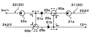
- the discharge port side of the high temperature side water pump 21a of the high pressure side heat medium circulation circuit 21 and the suction port side of the low temperature side water pump 22a of the low pressure side heat medium circulation circuit 22 are connected via the first connection flow path 25a.
- the outlet side of the radiator 24 of the low-pressure side heat medium circulation circuit 22 and the inlet side of the water passage of the high-temperature side water-refrigerant heat exchanger 12 of the high-pressure side heat medium circulation circuit 21 are connected via a second connection flow path 25b. ing.
- a first cooling water flow rate adjusting valve 26a for adjusting the flow rate of the cooling water flowing through the first connecting flow channel 25a is disposed in the first connecting flow channel 25a.
- a second cooling water flow rate adjustment valve 26b that adjusts the flow rate of the cooling water flowing through the second connection flow channel 25b is disposed in the second connection flow channel 25b.
- Each of the first and second cooling water flow rate adjusting valves 26a and 26b includes a valve body configured to change the opening degree and an electric actuator that changes the opening degree by displacing the valve body. This is an electric flow control valve.
- the operations of the first and second cooling water flow rate adjustment valves 26 a and 26 b are controlled by a control signal output from the air conditioning control device 40.
- the high-pressure side heat medium circulation circuit 21 includes the high-temperature side water-refrigerant heat exchanger 12, the heater core 23, In the low-pressure side heat medium circuit 22, the cooling water circulates between the radiator 24 and the inverter Inv. Therefore, the cooling water circulating through the high-pressure side heat medium circulation circuit 21 and the cooling water circulating through the low-pressure side heat medium circulation circuit 22 do not mix.
- the air conditioning control device 40 opens the first and second cooling water flow rate adjustment valves 26a and 26b, a part of the cooling water that circulates through the high-pressure side heat medium circulation circuit 21 according to the opening degree. However, a part of the cooling water that flows into the low-pressure side heat medium circulation circuit 22 through the first connection flow path 25a and the high-pressure flow through the low-pressure side heat medium circulation circuit 22 passes through the second connection flow path 25b. It flows into the side heat medium circulation circuit 21.
- a part of the cooling water flowing out from the heater core 23 can be made to flow into the inverter Inv by opening the first and second cooling water flow rate adjusting valves 26a and 26b. Furthermore, the cooling water flowing out from the inverter Inv can be introduced into the radiator 24, and a part of the cooling water flowing out from the radiator 24 can be returned to the water passage side of the high temperature side water-refrigerant heat exchanger 12.
- the air-conditioning control device 40 adjusts the opening degree of the first and second cooling water flow rate adjustment valves 26a and 26b, so that the cooling water flowing out from the heater core 23 arranged in the high-pressure side heat medium circulation circuit 21.
- the flow rate of the cooling water flowing into the radiator 24 arranged in the low-pressure side heat medium circulation circuit 22 can be adjusted.
- the first and second cooling water flow rate adjustment valves 26a and 26b constitute the heat medium flow rate adjustment device described in the claims.
- the air conditioning control device 40 opens the first and second cooling water flow rate adjusting valves 26a and 26b, the flow rate and the low pressure side heat flowing from the high pressure side heat medium circulation circuit 21 to the low pressure side heat medium circulation circuit 22 are opened.
- the flow rate returning from the medium circulation circuit 22 to the high-pressure side heat medium circulation circuit 21 may transiently differ, the flow rate eventually converges to the same flow rate.
- the flow rate after convergence is described as a bypass flow rate.
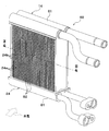
- the outdoor heat exchanger 14 and the radiator 24 of the present embodiment are each provided with a plurality of tubes through which the refrigerant or cooling water flows, and the refrigerant or cooling water that is arranged on both ends of the plurality of tubes and flows through the tubes. It is configured as a so-called tank-and-tube type heat exchanger having a pair of collecting / distributing tanks for collecting or distributing.
- the outdoor heat exchanger 14 has a plurality of refrigerant tubes 14a through which the refrigerant flows.
- the refrigerant tube 14a as shown in the cross-sectional view of FIG. 3, a multi-hole flat tube having a flat vertical cross-sectional shape in the longitudinal direction is adopted, and each of the refrigerant tubes 14a has an outer surface.
- the flat surfaces are laminated and arranged at a predetermined interval so that they are opposed to each other in parallel.
- an endothermic air passage 14b through which the outside air blown from the blower fan 14a is circulated is formed around the refrigerant tube 14a, that is, between the adjacent refrigerant tubes 14a.
- the radiator 24 has a plurality of heat medium tubes 24a through which cooling water flows.
- the heat medium tube 24a as shown in the cross-sectional view of FIG. 3, a single-hole flat tube having a flat vertical cross-sectional shape in the longitudinal direction is adopted, and similarly to the refrigerant tube 14a, the heat medium The tubes 24a are laminated and arranged at predetermined intervals so that the flat surfaces of the outer surface are parallel to each other and face each other.
- a heat radiation air passage 24b is formed around the heat medium tube 24a, that is, between the adjacent heat medium tubes 24a, for circulating the outside air blown from the blower fan 14a.
- a part of the collective distribution tank 61 of the outdoor heat exchanger 14 and the radiator 24 is formed by the same member, and the heat absorbing air passage 14b and the heat radiating air passage 24b are formed by the same member.
- the outer fin 62 is disposed.
- the outdoor heat exchanger 14 and the radiator 24 are integrated as the heat exchanger structure 60 by joining the outer fin 62 to both the tubes 14a and 24a.
- the outer fin 62 a corrugated fin obtained by bending a metal thin plate having excellent heat conductivity into a wave shape is employed.
- the portion disposed in the heat absorbing air passage 14b functions to promote heat exchange between the refrigerant and the outside air
- the portion disposed in the heat radiating air passage 24b is the heat generated between the cooling water and the outside air. Acts to facilitate exchange.
- the outer fin 62 is joined to both the refrigerant tube 14a and the heat medium tube 24a, thereby enabling the heat transfer between the refrigerant tube 14a and the heat medium tube 24a. Fulfill. Therefore, the outdoor heat exchanger 14 and the radiator 24 are integrated so that heat transfer between the refrigerant flowing through the outdoor heat exchanger 14 and the refrigerant flowing through the radiator 24 is possible.
- the function of exchanging heat between the refrigerant (first fluid) and the outside air (third fluid) and the cooling water (second fluid) and the outside air (third fluid) are provided.
- it has a function of exchanging heat between the refrigerant (first fluid) and the cooling water (second fluid).
- the heat exchanger structure 60 is configured as a composite heat exchanger or a three-fluid heat exchanger that can perform heat exchange between three types of fluids. Further, the radiator 24 converts the heat of the cooling water flowing out from the heater core 23 into the low-pressure refrigerant flowing through the refrigerant flow path from the outlet side of the heating expansion valve 13 to the compressor 11 inlet side at least in the heating mode. A heat medium heat radiating section for radiating heat is configured.
- the refrigerant tube 14a of the outdoor heat exchanger 14 of the present embodiment, the heat medium tube 24a of the radiator 24, the collective distribution tank 61, the outer fins 62, and the like are all formed of an aluminum alloy. It is integrated by being attached. Furthermore, in this embodiment, the radiator 24 is integrated with the outdoor heat exchanger 14 so as to be arranged on the windward side in the flow direction of the outside air blown by the blower fan 14a.
- the indoor air conditioning unit 30 is for blowing out the blown air whose temperature has been adjusted by the heat pump system 1 into the vehicle interior, and is disposed inside the instrument panel (instrument panel) at the forefront of the vehicle interior. Furthermore, the indoor air conditioning unit 30 is configured by housing a blower 32, an indoor evaporator 17, a heater core 23, and the like in a casing 31 that forms an outer shell thereof.
- the casing 31 forms an air passage for the blown air blown into the passenger compartment, and is formed of a resin (for example, polypropylene) having a certain degree of elasticity and excellent in strength.
- An inside / outside air switching device 33 as an inside / outside air switching unit that switches and introduces inside air (vehicle compartment air) and outside air (vehicle compartment outside air) into the casing 31 is arranged on the most upstream side of the blown air flow in the casing 31. ing.
- the inside / outside air switching device 33 continuously adjusts the opening area of the inside air introduction port through which the inside air is introduced into the casing 31 and the outside air introduction port through which the outside air is introduced by the inside / outside air switching door, so that the air volume of the inside air and the air volume of the outside air are adjusted.
- the air volume ratio is continuously changed.
- the inside / outside air switching door is driven by an electric actuator for the inside / outside air switching door, and the operation of the electric actuator is controlled by a control signal output from the air conditioning control device 40.
- a blower (blower) 32 is disposed as a blower that blows the air sucked through the inside / outside air switching device 33 toward the vehicle interior.
- the blower 32 is an electric blower that drives a centrifugal multiblade fan (sirocco fan) with an electric motor, and the number of rotations (air flow rate) is controlled by a control voltage output from the air conditioning control device 40.
- the indoor evaporator 17 and the heater core 23 are arranged in this order with respect to the flow of the blown air. Further, in the casing 31, a cold air bypass passage 35 is formed in which the blown air that has passed through the indoor evaporator 17 bypasses the heater core 23 and flows downstream.
- a mix door 34 is arranged on the downstream side of the blower air flow of the indoor evaporator 17 and on the upstream side of the blower air flow of the heater core 23, the air that adjusts the air volume ratio that passes through the heater core 23 among the blown air that has passed through the indoor evaporator 17.
- a mixing space for mixing the blown air heated by the heater core 23 and the blown air that has passed through the cold air bypass passage 35 and is not heated by the heater core 23 is provided on the downstream side of the blower air flow of the heater core 23. ing. Furthermore, the opening hole which blows off the ventilation air (air-conditioning wind) mixed in the mixing space to the vehicle interior which is an air-conditioning object space is arrange
- the opening hole includes a face opening hole that blows air-conditioned air toward the upper body of the passenger in the passenger compartment, a foot opening hole that blows air-conditioned air toward the feet of the passenger, and an inner surface of the front window glass of the vehicle.
- a defroster opening hole (both not shown) for blowing the conditioned air toward is provided. The air flow downstream of these face opening holes, foot opening holes, and defroster opening holes is connected to the face air outlet, foot air outlet, and defroster air outlet provided in the vehicle interior via ducts that form air passages, respectively. Neither is shown).
- the air mix door 34 adjusts the air volume ratio between the air volume passing through the heater core 23 and the air volume passing through the cold air bypass passage 35, thereby adjusting the temperature of the conditioned air mixed in the mixing space.
- the temperature of the blast air (air conditioned air) blown out from the air outlet into the vehicle compartment is adjusted.
- the air mix door 34 constitutes a temperature adjustment device that adjusts the temperature of the conditioned air blown into the vehicle interior.
- the air mix door 34 is driven by an electric actuator for driving the air mix door, and the operation of the electric actuator is controlled by a control signal output from the air conditioning control device 40.
- a face door for adjusting the opening area of the face opening hole a foot door for adjusting the opening area of the foot opening hole, and a defroster opening, respectively.
- a defroster door (both not shown) for adjusting the opening area of the hole is disposed.
- These face doors, foot doors, and defroster doors constitute an opening hole mode switching unit that switches the opening hole mode, and are linked to an electric actuator for driving the outlet mode door via a link mechanism or the like. And rotated.
- the operation of this electric actuator is also controlled by a control signal output from the air conditioning control device 40.
- a face mode in which the face air outlet is fully opened and air is blown out from the face air outlet toward the upper body of the passenger in the passenger compartment, the face air outlet and the foot air outlet
- the bi-level mode that opens both of the air outlets and blows air toward the upper body and feet of passengers in the passenger compartment, fully opens the foot outlet and opens the defroster outlet by a small opening, and mainly draws air from the foot outlet.
- the defroster mode in which the occupant manually operates the blowing mode changeover switch provided on the operation panel to fully open the defroster outlet and blow out air from the defroster outlet to the inner surface of the front windshield of the vehicle.
- the air conditioning control device 40 includes a known microcomputer including a CPU, a ROM, a RAM, and the like and peripheral circuits thereof. Then, various calculations and processes are performed based on the air conditioning control program stored in the ROM, and the various control target devices 11, 13, 14a, 16, 18a, 21a, 22a, 26a, 26b connected to the output side thereof. , 32, 34, etc. are controlled.
- an outside air sensor serving as an inside air temperature detector for detecting a vehicle interior temperature (inside air temperature) Tr and an outside air detector serving as an outside air temperature detector for detecting a vehicle interior outside temperature (outside air temperature) Tam
- a solar radiation sensor as a solar radiation detector for detecting the solar radiation amount As irradiated into the passenger compartment, a discharge temperature sensor for detecting the refrigerant discharge temperature Td of the refrigerant discharged from the compressor 11, and a refrigerant discharge pressure of the refrigerant discharged from the compressor 11
- a discharge pressure sensor for detecting high-pressure side refrigerant pressure (Pd)
- an evaporator temperature sensor for detecting refrigerant evaporation temperature (evaporator temperature) Tefin in the indoor evaporator 17, and an air temperature TAV for blowing air from the mixed space into the vehicle interior.
- a group of sensors for air conditioning control such as an air temperature sensor that detects the temperature of the outdoor heat exchanger and
- the evaporator temperature sensor of this embodiment has detected the heat exchange fin temperature of the indoor evaporator 17, the temperature detector which detects the temperature of the other site
- a temperature detector that detects the temperature of the refrigerant flowing through the indoor evaporator 17 may be used.
- outdoor heat exchanger temperature sensor of this embodiment has detected the temperature of the refrigerant
- other outdoor heat exchanger 14 sensors are used as an outdoor heat exchanger temperature sensor.
- a temperature detector that detects the temperature of the part may be employed, or a temperature detector that detects the temperature of the refrigerant flowing through the outdoor heat exchanger 14 may be employed.
- the ventilation air temperature sensor which detects blowing air temperature TAV is provided, the value calculated based on evaporator temperature Tefin, discharge refrigerant temperature Td, etc. is employ
- an operation panel (not shown) disposed near the instrument panel in the front part of the passenger compartment is connected to the input side of the air conditioning control device 40, and operation signals from various operation switches provided on the operation panel are input. .
- various operation switches provided on the operation panel include an auto switch for setting or canceling the automatic control operation of the vehicle air conditioner, a cooling switch for requesting cooling of the vehicle interior, and an air volume of the blower 32.
- the air-conditioning control device 40 is configured such that a control unit that controls various control target devices connected to the output side thereof is integrally configured. However, the configuration controls the operation of each control target device. (Hardware and Software) constitutes a control unit that controls the operation of each control target device.
- the configuration (hardware and software) that controls the refrigerant discharge capability of the compressor 11 constitutes the discharge capability control unit 40a
- the heat medium flow control device in this embodiment, the structure which controls the action
- the discharge capacity control unit 40a, the heat medium flow rate control unit 40b, and the like may be configured as separate control devices for the air conditioning control device 40.
- the operation in the cooling mode, the dehumidifying heating mode, and the heating mode can be switched. Switching between these operation modes is performed by executing an air conditioning control program.
- This air conditioning control program is executed when the auto switch of the operation panel is turned on.
- the detection signals of the above-described sensor group for air conditioning control and operation signals from various air conditioning operation switches are read. And based on the value of the read detection signal and operation signal, the target blowing temperature TAO which is the target temperature of the blowing air which blows off into the vehicle interior is calculated based on the following formula F1.
- TAO Kset ⁇ Tset ⁇ Kr ⁇ Tr ⁇ Kam ⁇ Tam ⁇ Ks ⁇ As + C (F1)
- Tset is the target temperature in the vehicle interior (the vehicle interior set temperature) set by the temperature setting switch
- Tr is the vehicle interior temperature (internal air temperature) detected by the internal air sensor
- Tam is the external air temperature detected by the external air sensor
- As is the amount of solar radiation detected by the solar radiation sensor.
- Kset, Kr, Kam, Ks are control gains
- C is a correction constant.
- the operation in the cooling mode is executed.
- the cooling switch is turned on and the target blowing temperature TAO is equal to or higher than the cooling reference temperature ⁇
- the operation in the dehumidifying heating mode is executed.
- the cooling switch is not turned on, the operation in the heating mode is executed.
- the operation in the cooling mode is executed, and in the dehumidifying heating mode mainly in early spring or early winter.
- the operation in the heating mode is executed.
- the operation in the heating end mode is executed when the heating mode ends. The operation in each operation mode will be described below.
- (A) Cooling mode In the cooling mode, the air-conditioning control device 40 operates the high temperature side water pump 21a and the low temperature side water pump 22a so as to exhibit a predetermined water pumping capacity, and adjusts the first and second cooling water flow rates.
- the valves 26a and 26b are fully closed.
- the bypass flow rate becomes 0, so that the cooling water circulating in the high-pressure side heat medium circulation circuit 21 and the cooling water circulating in the low-pressure side heat medium circulation circuit 22 are mixed. Rather, cooling water circulates through each heat medium circuit.
- the air-conditioning control device 40 opens the heating expansion valve 13 fully, places the cooling expansion valve 16 in a throttle state that exerts a pressure reducing action, and closes the heating on-off valve 18a.
- the compressor 11 ⁇ the high temperature side water-refrigerant heat exchanger 12 ( ⁇ the heating expansion valve 13) ⁇ the outdoor heat exchanger 14 ⁇
- a vapor compression refrigeration cycle in which the refrigerant circulates in the order of the cooling expansion valve 16 ⁇ the indoor evaporator 17 ⁇ the accumulator 19 ⁇ the compressor 11 is configured.
- the air-conditioning control device 40 operates the operation states of the various control target devices (output to the various control target devices based on the target blowing temperature TAO and the detection signal of the sensor group). Control signal) to be determined.
- the refrigerant discharge capacity of the compressor 11, that is, the control signal output to the electric motor of the compressor 11 is determined as follows. First, the target evaporator outlet temperature TEO of the indoor evaporator 17 is determined based on the target outlet temperature TAO with reference to a control map stored in the air conditioning controller 40 in advance.
- the target evaporator blowout temperature TEO is determined to decrease as the target blowout temperature TAO decreases. Further, the target evaporator blowout temperature TEO is determined to be equal to or higher than a reference frost prevention temperature (for example, 1 ° C.) determined to be able to suppress frost formation in the indoor evaporator 17.
- a reference frost prevention temperature for example, 1 ° C.
- the evaporator temperature Tefin approaches the target evaporator outlet temperature TEO using a feedback control method.
- the control signal output to the electric motor of the compressor 11 is determined.
- control voltage output to the blower 32 is determined with reference to a control map stored in advance in the air conditioning control device 40 based on the target blowing temperature TAO. Specifically, in this control map, the air volume of the blower 32 is set to the maximum air volume in the extremely low temperature region (maximum cooling region) and the extremely high temperature region (maximum heating region) of the target blowing temperature TAO.
- the air blowing amount is decreased according to the increase in the target blowing temperature TAO, and the target blowing temperature TAO is changed from the extremely high temperature range to the intermediate temperature range.
- the air pressure decreases, the air flow rate is decreased according to the decrease in the target air temperature TAO.
- the blowing amount is set as the minimum blowing amount.
- the air mix door 34 closes the air passage on the heater core 23 side, and the total air volume of the blown air after passing through the indoor evaporator 17 is the heater core 23. Is determined to flow around.
- the degree of supercooling of the refrigerant flowing into the cooling expansion valve 16 is determined by referring to a control map stored in the air conditioning control device 40 in advance.
- the coefficient of performance (COP) is determined so as to approach the target degree of supercooling determined so as to be approximately the maximum value.
- control voltage output to the blower fan 14a is determined so that the blower fan 14a exhibits a predetermined blowing ability according to the operation mode.
- control signals determined as described above are output to various control target devices. After that, until the operation stop of the vehicle air conditioner is requested, reading the above detection signal and operation signal at every predetermined control cycle ⁇ calculating the target blowing temperature TAO ⁇ determining the operating state of various control target devices ⁇ control voltage And the control routine such as the output of the control signal is repeated. Such a control routine is repeated in the other operation modes.
- the high-pressure refrigerant discharged from the compressor 11 flows into the refrigerant passage of the high temperature side water-refrigerant heat exchanger 12.
- the temperature of the cooling water flowing into the water passage of the high temperature side water-refrigerant heat exchanger 12 is lower than the temperature of the high pressure refrigerant flowing into the high temperature side water-refrigerant heat exchanger 12, The heat it has is radiated to the cooling water, and the cooling water circulating through the high-pressure side heat medium circulation circuit 21 is heated.
- the high-pressure refrigerant flows into the high-temperature side water-refrigerant heat exchanger 12. However, it flows out from the high temperature side water-refrigerant heat exchanger 12 with almost no heat exchange with the cooling water.
- the refrigerant flowing into the outdoor heat exchanger 14 is blown by the outdoor heat exchanger 14 from the blower fan 14 a and exchanges heat with the outside air after passing through the radiator 24 to radiate heat.
- the cooling water circulating in the low-pressure-side heat medium circulation circuit 22 exchanges heat with the outside air blown from the blower fan 14a to dissipate heat. More specifically, in the radiator 24, the heat absorbed from the inverter Inv when the cooling water circulates through the low-pressure side heat medium circuit 22 is radiated to the outside air.
- the refrigerant that has flowed out of the outdoor heat exchanger 14 is reduced in pressure until it flows into the cooling expansion valve 16 via the low-pressure side branch portion 15a and becomes low-pressure refrigerant.
- the refrigerant decompressed by the cooling expansion valve 16 flows into the indoor evaporator 17, absorbs heat from the blown air blown from the blower 32, and evaporates.
- the refrigerant that has flowed out of the indoor evaporator 17 flows into the accumulator 19 through the junction 15b and is separated into gas and liquid.
- the gas-phase refrigerant separated by the accumulator 19 is sucked into the compressor 11 and compressed again.
- the vehicle interior can be cooled by blowing the blown air cooled by the indoor evaporator 17 into the vehicle interior.
- the refrigerant circulating through the low-pressure-side heat medium circuit 22 radiates heat absorbed from the inverter Inv to the outside air by the radiator 24, whereby the inverter Inv can be cooled.
- This is effective in operating conditions in which the outside air temperature is relatively high and the temperature of the inverter Inv is likely to rise, such as in summer when the operation in the cooling mode is mainly performed.
- (B) Dehumidification heating mode In the dehumidification heating mode, the air-conditioning control device 40 operates the high-temperature side water pump 21a and the low-temperature side water pump 22a so as to exhibit a predetermined water pressure-feeding capability, as in the cooling mode, 1.
- the second cooling water flow rate adjusting valves 26a and 26b are fully closed.
- the bypass flow rate becomes 0, so that the cooling water circulating in the high-pressure side heat medium circulation circuit 21 and the cooling water circulating in the low-pressure side heat medium circulation circuit 22 are mixed. Rather, cooling water circulates through each heat medium circuit.
- the air-conditioning control device 40 sets the heating expansion valve 13 to the throttle state, fully opens the cooling expansion valve 16, and closes the heating on-off valve 18a.
- the compressor 11 ⁇ the high temperature side water-refrigerant heat exchanger 12 ⁇ the heating expansion valve 13 ⁇ the outdoor heat exchanger 14 ( ⁇ Cooling expansion valve 16) ⁇ Vapor compression refrigeration cycle in which the refrigerant circulates in the order of indoor evaporator 17 ⁇ accumulator 19 ⁇ compressor 11. That is, in the dehumidifying and heating mode, a refrigeration cycle in which the refrigerant circulates in the same order as in the cooling mode is configured.
- the air-conditioning control device 40 operates the operation states of the various control target devices (output to the various control target devices based on the target blowing temperature TAO and the detection signal of the sensor group). Control signal) to be determined.
- control signal output to the electric motor of the compressor 11, the control voltage output to the blower 32, and the control voltage output to the blower fan 14a are determined in the same manner as in the cooling mode.
- control signal output to the heating expansion valve 13 is such that the degree of supercooling of the refrigerant flowing into the heating expansion valve 13 approaches the target supercooling degree determined so that the COP becomes substantially the maximum value. To be determined. Moreover, about the control signal output to the electric actuator of the air mix door 34, it determines so that the ventilation air temperature TAV may approach the target blowing temperature TAO.
- the high-pressure refrigerant discharged from the compressor 11 flows into the high-temperature side water-refrigerant heat exchanger 12. Thereby, the cooling water circulating through the high-pressure side heat medium circulation circuit 21 is heated.
- the air mix door 34 opens the air passage on the heater core 23 side, so that the cooling water heated by the high temperature side water-refrigerant heat exchanger 12 flows into the heater core 23, Part of the blown air after passing through the evaporator 17 is heated.
- the temperature of the blown air that is blown from the mixed space of the indoor air conditioning unit 30 into the vehicle interior approaches the target blowing temperature TAO.
- the refrigerant that has flowed out of the refrigerant passage of the high-temperature side water-refrigerant heat exchanger 12 flows into the heating expansion valve 13 and is decompressed until it becomes a low-pressure refrigerant.
- the low-pressure refrigerant decompressed by the heating expansion valve 13 flows into the outdoor heat exchanger 14.
- the refrigerant flowing into the outdoor heat exchanger 14 is blown by the outdoor heat exchanger 14 from the blower fan 14a and absorbs heat from the outside air after passing through the radiator 24 to evaporate.
- the refrigerant circulating in the low-pressure side heat medium circuit 22 exchanges heat with the outside air blown from the blower fan 14a to dissipate heat.
- the refrigerant that has flowed out of the outdoor heat exchanger 14 flows into the indoor evaporator 17 through the low pressure side branching portion 15a and the cooling expansion valve 16 that is fully open because the heating on-off valve 18a is closed.
- the refrigerant flowing into the indoor evaporator 17 further absorbs heat and evaporates from the blown air blown from the blower 32. Thereby, blowing air is cooled and dehumidification of blowing air is made.
- the subsequent operation is the same as in the cooling mode.
- the air that has been cooled and dehumidified by the indoor evaporator 17 is reheated by the heater core 23 and blown out into the vehicle interior, thereby performing dehumidification heating in the vehicle interior.
- the inverter Inv can be cooled by dissipating the heat absorbed by the refrigerant circulating in the low-pressure side heat medium circuit 22 from the inverter Inv to the outside air or the like by the radiator 24.
- the heat exchanger structure 60 in which the outdoor heat exchanger 14 and the radiator 24 are integrated is adopted, the heat of the cooling water flowing through the radiator 24 is transferred to the outdoor heat exchanger 14. It is possible to transfer heat to the refrigerant circulating. Therefore, the waste heat of the inverter Inv absorbed by the cooling water can be effectively used as a heat source for reheating the dehumidified blown air.
- the first and second cooling water flow rate adjustment valves 26a and 26b are fully closed, so that the cooling water and the low pressure side heat medium circulation circuit that circulate in the high pressure side heat medium circulation circuit 21 are used.
- the cooling water circulating through 22 does not mix. Therefore, at the time of the dehumidifying heating mode, for example, even if the outside air temperature decreases and the heat absorption amount of the refrigerant in the outdoor heat exchanger 14 decreases, the heat stored in the cooling water circulating in the high-pressure side heat medium circuit 21 The dehumidified blown air can be reheated.
- (C) Heating mode In the heating mode, the air conditioning control device 40 operates the high-temperature side water pump 21a and the low-temperature side water pump 22a so as to exhibit a predetermined water pumping capacity, and adjusts the first and second cooling water flow rates.
- the valves 26a and 26b are opened.
- the heat medium circulation circuit 20 in the heating mode not only the cooling water circulates through the respective heat medium circulation circuits 21 and 22, but also a part of the cooling water circulated through the high-pressure side heat medium circulation circuit 21.
- a part of the cooling water that flows into the low-pressure side heat medium circulation circuit 22 through the connection flow path 25a and circulates in the low-pressure side heat medium circulation circuit 22 passes through the second connection flow path 25b.
- the air-conditioning control device 40 sets the heating expansion valve 13 to the throttle state, fully closes the cooling expansion valve 16, and opens the heating on-off valve 18a.
- the air-conditioning control device 40 operates the operation states of the various control target devices (output to the various control target devices based on the target blowing temperature TAO and the detection signal of the sensor group). Control signal) to be determined.
- the refrigerant discharge capacity of the compressor 11, that is, the control signal output to the electric motor of the compressor 11 is determined as follows.
- the target condensing temperature TCO in the high temperature side water-refrigerant heat exchanger 12 is determined based on the target blowing temperature TAO with reference to a control map stored in the air conditioning control device 40 in advance. Specifically, in this control map, the target condensing temperature TCO is determined to increase as the target blowing temperature TAO increases.
- a feedback control method is used so that the discharge refrigerant temperature Td approaches the target condensation temperature TCO.
- a control signal output to the electric motor of the compressor 11 is determined so that an abnormal increase in the refrigerant pressure Pd is suppressed.
- control voltage output to the blower 32 and the control voltage output to the blower fan 14a are determined in the same manner as in the cooling mode.
- the control signal output to the heating expansion valve 13 is determined in the same manner as in the dehumidifying heating mode.
- the air mix door 34 closes the cold air bypass passage 35, and the total air volume of the blown air after passing through the indoor evaporator 17 is the air passage on the heater core 23 side. Is determined to pass.
- a high pressure side A target bypass flow rate to be introduced from the heat medium circulation circuit 21 to the low pressure side heat medium circulation circuit 22, that is, a target bypass flow rate to be returned from the low pressure side heat medium circulation circuit 22 to the high pressure side heat medium circulation circuit 21 is determined.
- the target bypass flow rate is determined to increase as the target blowing temperature TAO increases.
- the control signal output to the 1st, 2nd cooling water flow rate adjustment valve 26a, 26b is determined so that it may become the determined target bypass flow rate.
- the above-described target blowing temperature TAO is a value determined in order to keep the actual vehicle interior temperature at the vehicle interior set temperature Tset corresponding to the desired temperature of the occupant. Therefore, as in the heating mode of the present embodiment, in the heat pump cycle 10 that heats the blown air using the cooling water heated by the high temperature side water-refrigerant heat exchanger 12 as a heat source, as the target blowing temperature TAO increases. The heating capacity of the blown air required for the heat pump cycle 10 is increased.
- the heat medium flow rate control unit 40b includes the first and second cooling water flow rate adjustment valves 26a, so that the cooling water bypass flow rate returning from the low pressure side heat medium circulation circuit 22 to the high pressure side heat medium circulation circuit 21 increases.
- the operation of 26b is controlled.
- the high-pressure refrigerant discharged from the compressor 11 flows into the high-temperature side water-refrigerant heat exchanger 12 and enters the high-pressure side heat medium circulation circuit 21.
- the circulating cooling water is heated.
- the air mix door 34 fully opens the air passage on the heater core 23 side, the heated warm water flows into the heater core 26, whereby the blown air after passing through the indoor evaporator 17 is heated.
- the refrigerant flowing out of the high temperature side water-refrigerant heat exchanger 12 flows into the heating expansion valve 13 and is decompressed until it becomes a low pressure refrigerant.
- the low-pressure refrigerant decompressed by the heating expansion valve 13 flows into the outdoor heat exchanger 14.
- the refrigerant that has flowed into the outdoor heat exchanger 14 is blown from the blower fan 14a by the outdoor heat exchanger 14 and absorbs heat from the outside air after passing through the radiator 24 to evaporate.
- the refrigerant circulating in the low-pressure side heat medium circulation circuit 22 exchanges heat with the outside air blown from the blower fan 14a to radiate heat.
- the refrigerant that has flowed out of the outdoor heat exchanger 14 flows into the accumulator 19 through the low pressure side branch portion 15a and the accumulator side passage 18 and is separated into gas and liquid because the heating on-off valve 18a is open.
- the gas-phase refrigerant separated by the accumulator 19 is sucked into the compressor 11 and compressed again as in the cooling mode and the dehumidifying heating mode.
- the heat medium circulation circuit 20 in the heating mode since the first and second cooling water flow rate adjustment valves 26a and 26b are opened, a part of the cooling water flowing out from the heater core 23 of the high pressure side heat medium circulation circuit 21 is generated. Then, it flows into the inverter Inv of the low-pressure side heat medium circulation circuit 22. Further, the cooling water flowing out from the inverter Inv flows into the radiator 24, and a part of the cooling water flowing out from the radiator 24 returns to the water passage of the high temperature side water-refrigerant heat exchanger 12 of the high pressure side heat medium circulation circuit 21.
- the vehicle interior can be heated by blowing the blown air heated by the heater core 23 into the vehicle interior.
- the heat exchanger structure 60 in which the outdoor heat exchanger 14 and the radiator 24 are integrated is adopted, the heat of the cooling water flowing through the radiator 24 is transferred to the outdoor heat exchanger 14. It is possible to transfer heat to the refrigerant circulating. Therefore, the waste heat absorbed by the cooling water from the inverter Inv can be effectively used as a heat source for heating the blown air.
- the heating end mode is an operation mode that is executed when the heating mode is ended, that is, an operation mode that is executed when a stop of heating of the blown air by the heat pump cycle 10 is requested.
- the operation in the heating end mode is performed until a predetermined time elapses after the occupant turns off the auto switch of the operation panel during the heating mode.
- the air conditioning control device 40 stops the compressor 11 and the blower 32. Therefore, in the heating end mode, the heat pump cycle 10 does not exhibit the function of adjusting the temperature of the cooling water and the blown air. Further, the air conditioning control device 40 operates the high temperature side water pump 21a and the low temperature side water pump 22a so as to exhibit a predetermined water pressure feeding capacity, and fully opens the first and second cooling water flow rate adjustment valves 26a, 26b. To do.
- the heating medium circulation circuit 20 in the heating end mode as in the heating mode, a part of the cooling water circulating in the high-pressure side heat medium circulation circuit 21 flows into the low-pressure side heat medium circulation circuit 22, and the low-pressure side heat medium A part of the cooling water circulating through the circulation circuit 22 returns to the high-pressure side heat medium circulation circuit 21.
- the first and second cooling water flow rate adjustment valves 26a and 26b are fully opened, so that the bypass flow rate increases compared to the heating mode.
- the flow rate of the cooling water flowing into the radiator 24 arranged in the low-pressure side heat medium circulation circuit 22 out of the high-temperature cooling water flowing out from the heater core 23 is larger than that in the heating mode.
- the temperature of the cooling water circulating through the low-pressure side heat medium circulation circuit 22 can be increased as compared with the heating mode.
- the heat pump system 1 operates as described above, and can perform cooling, dehumidification heating, and heating in the passenger compartment. Furthermore, according to the heat pump system 1 of the present embodiment, excellent effects can be obtained in the heating mode and the heating end mode, as described below.
- the heating mode is generally an operation mode that is executed when the outside air temperature is relatively low as in winter. Therefore, in the heating mode, the refrigerant evaporation temperature in the outdoor heat exchanger 14 of the heat pump cycle 10 is also likely to decrease. Furthermore, when the refrigerant
- FIG. 1 the refrigerant evaporation temperature in the outdoor heat exchanger 14 of the heat pump cycle 10 is also likely to decrease. Furthermore, when the refrigerant
- the radiator 24 is provided as the heat medium heat radiating section, the heat of the cooling water circulating in the heat medium circulation circuit 20 is used as the low-pressure refrigerant of the heat pump cycle 10. Can dissipate heat.
- the refrigerant evaporating temperature in the outdoor heat exchanger 14 can be increased and frost formation in the outdoor heat exchanger 14 can be suppressed regardless of the operating state of the inverter Inv that is an external heat source. Further, in the heating end mode, this can be defrosted by the heat transferred from the cooling water to the outdoor heat exchanger 14 regardless of the operating state of the inverter Inv that is an external heat source.
- the radiator 24 dissipates the heat of the cooling water flowing out of the heater core 23 to the outside air and the outdoor heat exchanger 14, the heat of the cooling water heated by the high temperature side water-refrigerant heat exchanger 12 is blown. It can be used for heating the air, and the excess heat can be used for defrosting the outdoor heat exchanger 14 or suppressing frost formation. Therefore, it is possible to suppress the frost formation of the outdoor heat exchanger 14 without increasing the energy consumption of the compressor 11.
- the defrosting or the defrosting of the outdoor heat exchanger 14 is performed without depending on the heat supplied from an external heat source or the like and without increasing the energy consumption of the compressor 11. Suppression of frost formation can be realized.
- the heat exchanger structure 60 is employ
- the heat pump system 1 of the present embodiment includes the first and second cooling water flow rate adjusting valves 26a and 26b as the heat medium flow rate adjusting devices, the amount of heat radiated from the cooling water to the low-pressure refrigerant is appropriately set. Can be adjusted.
- the flow rate of the cooling water flowing out from the heater core 23 and flowing into the radiator 24 is increased as the heating capacity of the blown air required for the heat pump cycle 10 increases.
- the temperature of the cooling water circulating in the low-pressure side heat medium circulation circuit 22 is increased, and the frost formation of the outdoor heat exchanger 14 Can be efficiently suppressed.
- the flow rate of the cooling water flowing out from the heater core 23 and flowing into the radiator 24 is increased when it is requested to stop the heating of the blown air by the heat pump cycle 10.
- the outdoor heat exchanger 14 can be quickly defrosted after the heating operation in the passenger compartment is completed.
- the outdoor heat exchanger 14 of the present embodiment is arranged so as to exchange heat between the refrigerant circulating inside and the outside air blown from the blower fan 14a and passed through the radiator 24. That is, the outdoor heat exchanger 14 is disposed downstream of the radiator 24 in the flow of the outside air blown from the blower fan 14a.
- Other configurations and operations of the heat pump system 1 are the same as those in the first embodiment.
- the heat of the cooling water flowing through the radiator 24 is indirectly transmitted through the outside air.
- heat can be transferred to the refrigerant flowing through the outdoor heat exchanger 14. Therefore, in the dehumidifying heating mode, the waste heat of the inverter Inv absorbed by the cooling water can be effectively used as a heat source for reheating the dehumidified blown air.
- the heat of the cooling water circulating in the heat medium circuit 20 is effectively used as a heat source for heating the blown air, regardless of the operating state of the inverter Inv. And can be used for suppressing frost formation of the outdoor heat exchanger 14. Further, in the heating end mode, similarly to the first embodiment, the heat of the cooling water circulating through the heat medium circulation circuit 20 is used for defrosting the outdoor heat exchanger 14 regardless of the operating state of the inverter Inv. Can be used.
- the outdoor heat exchanger 14 and the radiator 24 are configured by separate heat exchangers, defrosting or attachment of the outdoor heat exchanger 14 can be performed without using a complicated heat exchanger. Suppression of frost can be easily realized.
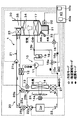
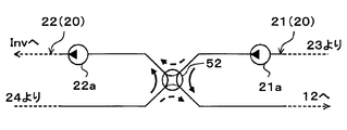
- a heat medium circuit 20 (specifically, the low-pressure side heat medium circuit 22) is used instead of the radiator 24.
- a low-temperature side water-refrigerant heat exchanger 27 that exchanges heat between circulating cooling water and low-pressure refrigerant (specifically, refrigerant flowing out of the outdoor heat exchanger 14) will be described.
- the basic configuration of the low temperature side water-refrigerant heat exchanger 27 is the same as that of the high temperature side water-refrigerant heat exchanger 12. Further, in the present embodiment, the low-temperature side water-refrigerant heat exchanger 27 constitutes a heat exchanger for radiating heat medium that exchanges heat between the cooling water flowing out from the heater core 23 and the low-pressure refrigerant.
- the structure of the other heat pump system 1 is the same as that of 1st Embodiment.
- the operation in the heating end mode is not performed.
- Other operations of the heat pump system 1 are the same as those in the first embodiment. Therefore, even if the heat pump system 1 of the present embodiment is operated, cooling, dehumidifying heating and heating in the passenger compartment can be performed, and the same effect as in the first embodiment can be obtained.
- the low-temperature refrigerant absorbs the heat of the cooling water flowing through the low-temperature side water-refrigerant heat exchanger 27 in the low-temperature side water-refrigerant heat exchanger 27. Can do. Therefore, in the dehumidifying heating mode, the waste heat of the inverter Inv absorbed by the cooling water can be effectively used as a heat source for reheating the dehumidified blown air.
- the heat of the cooling water circulating in the heat medium circuit 20 is effectively used as a heat source for heating the blown air, regardless of the operating state of the inverter Inv. And can be used for suppressing frost formation of the outdoor heat exchanger 14.
- the cooling water flowing out from the inverter Inv is heat-exchanged with the low-pressure refrigerant flowing out from the outdoor heat exchanger 14.
- Heat exchange with the circulating low-pressure refrigerant may be performed.
- the cooling water flowing out from the inverter Inv may be heat-exchanged with the low-pressure refrigerant flowing through the refrigerant flow path from the outlet side of the heating expansion valve 13 to the refrigerant inlet side of the outdoor heat exchanger 14.
- the compressor 11a two compression mechanisms, a low-stage compression mechanism and a high-stage compression mechanism, are provided inside a housing that forms the outer shell thereof, and A two-stage booster type electric compressor configured to accommodate an electric motor that rotationally drives both compression mechanisms is employed.
- An intermediate pressure suction port is provided for allowing the intermediate pressure refrigerant generated in the cycle from the outside to join the refrigerant in the compression process from low pressure to high pressure.
- the intermediate pressure suction port is connected to the refrigerant discharge port side of the low-stage compression mechanism (that is, the refrigerant suction port side of the high-stage compression mechanism).
- Various types such as a scroll type compression mechanism, a vane type compression mechanism, and a rolling piston type compression mechanism can be adopted as the low stage side compression mechanism and the high stage side compression mechanism, respectively.
- the compressor 11a which accommodated two compression mechanisms in one housing is employ
- adopted the format of a compressor is not limited to this. That is, if the intermediate pressure refrigerant can be introduced from the intermediate pressure suction port and merged with the refrigerant in the compression process from low pressure to high pressure, one fixed capacity type compression mechanism and the compression mechanism are provided inside the housing.
- An electric compressor configured to accommodate an electric motor that rotationally drives the motor may be employed.
- two compressors are connected in series, and the suction port of the low-stage compressor disposed on the low-stage side serves as the suction port of the entire two-stage booster compressor, and is disposed on the high-stage side.
- the discharge port of the high-stage compressor is the discharge port of the entire two-stage booster compressor, and the intermediate pressure is applied to the connection that connects the discharge port of the low-stage compressor and the suction port of the high-stage compressor.
- One two-stage booster compressor may be configured by providing two suction ports, ie, a low-stage compressor and a high-stage compressor.
- the refrigerant inlet of the gas-liquid separator 28, which is a gas-liquid separator that separates the gas-liquid of the refrigerant flowing out of the heating expansion valve 13, is connected to the outlet side of the heating expansion valve 13. ing.
- the gas-liquid separator 28 employs a centrifugal separation type that separates the gas-liquid refrigerant by the action of centrifugal force generated by swirling the refrigerant flowing into the internal space of the cylindrical main body. is doing. Furthermore, the internal volume of the gas-liquid separator 28 is a volume that cannot substantially store surplus refrigerant even if a load fluctuation occurs in the cycle and the refrigerant circulation flow rate circulating in the cycle fluctuates.
- the intermediate pressure suction port of the compressor 11 a is connected to the gas-phase refrigerant outlet of the gas-liquid separator 28. Further, a gas phase refrigerant passage opening / closing valve 18b for opening and closing the refrigerant passage is disposed in the refrigerant passage connecting the gas phase refrigerant outlet of the gas-liquid separator 28 and the intermediate pressure suction port of the compressor 11a.
- the basic configuration of the gas-phase refrigerant passage opening / closing valve 18b is the same as that of the heating opening / closing valve 18a.
- the air-conditioning control device 40 opens the gas-phase refrigerant passage opening / closing valve 18b, the gas-phase refrigerant flowing out from the gas-phase refrigerant outlet of the gas-liquid separator 28 moves to the intermediate pressure inlet side of the compressor 11a.
- the refrigerant circuit is switched to and the gas-phase refrigerant passage opening / closing valve 18b is closed, the refrigerant circuit is switched to a refrigerant circuit that does not allow the refrigerant to flow out from the gas-phase refrigerant outlet of the gas-liquid separator 28. Therefore, the gas-phase refrigerant passage opening / closing valve 18b constitutes a refrigerant circuit switching unit.
- the liquid-phase refrigerant outlet of the gas-liquid separator 28 is connected to the inlet side of an intermediate pressure fixed throttle 29 as a pressure reducing device that depressurizes the liquid-phase refrigerant separated by the gas-liquid separator 28.
- an intermediate pressure fixed throttle 29 As the intermediate pressure fixed throttle 29, a nozzle, an orifice, a capillary tube or the like having a fixed throttle opening can be employed.
- the refrigerant inlet side of the outdoor heat exchanger 14 is connected to the outlet side of the intermediate pressure fixed throttle 29.
- the liquid-phase refrigerant separated by the gas-liquid separator 28 is led to the refrigerant inlet side of the outdoor heat exchanger 14 by bypassing the intermediate pressure fixed throttle 29.
- a fixed throttle bypass passage 29a is connected.
- a bypass passage opening / closing valve 18c for opening and closing the fixed throttle bypass passage 29a is disposed in the fixed throttle bypass passage 29a.
- the basic configuration of the bypass passage opening / closing valve 18c is the same as that of the gas-phase refrigerant passage opening / closing valve 18b.
- the pressure loss that occurs when the refrigerant passes through the bypass passage opening / closing valve 18 c is extremely small compared to the pressure loss that occurs when the refrigerant passes through the intermediate pressure fixed throttle 29. Therefore, when the air conditioning control device 40 opens the bypass passage opening / closing valve 18c, the liquid-phase refrigerant that has flowed out of the gas-liquid separator 28 flows into the outdoor heat exchanger 14 through the fixed throttle bypass passage 29a. On the other hand, when the air-conditioning control device 40 closes the bypass passage opening / closing valve 18c, the outdoor heat exchanger 14 after the liquid refrigerant at the entire flow rate flowing out from the gas-liquid separator 28 is depressurized by the intermediate pressure fixed throttle 29. Flow into.
- a refrigerant pipe extending from the liquid-phase refrigerant outlet of the gas-liquid separator 28 to the refrigerant inlet side of the outdoor heat exchanger 14 is provided. You may arrange
- the structure of the other heat pump system 1 is the same as that of 1st Embodiment.
- the operation of the heat pump system 1 of the present embodiment having the above configuration will be described. Also in the heat pump system 1 of the present embodiment, the operations in the cooling mode, the dehumidifying heating mode, the heating mode, and the heating end mode can be performed as in the first embodiment. The operation in each operation mode will be described below.
- Cooling mode In the cooling mode of the present embodiment, the air conditioning control device 40 operates the high-temperature side water pump 21a and the low-temperature side water pump 22a so as to exhibit a predetermined water pressure-feeding capacity.
- the cooling water flow rate adjustment valves 26a and 26b are fully closed.
- the bypass flow rate becomes 0 as in the first embodiment, so that the cooling water circulating in the high-pressure side heat medium circulation circuit 21 and the low-pressure side heat medium circulation circuit 22 are changed.
- the circulating cooling water does not mix and the cooling water circulates through each heat medium circulation circuit.
- the air conditioning control device 40 fully opens the heating expansion valve 13, sets the cooling expansion valve 16 in a throttle state, closes the heating on-off valve 18a, closes the gas-phase refrigerant passage on-off valve 18b, and bypasses the on-off passage on-off valve 18c. open.
- a refrigeration cycle in which the refrigerant circulates in the same order as in the cooling mode of the first embodiment is configured.
- Other operations are the same as those in the cooling mode of the first embodiment. Therefore, in the cooling mode of the present embodiment, as in the cooling mode of the first embodiment, the vehicle interior can be cooled and the inverter Inv can be cooled.
- (B) Dehumidification heating mode In the dehumidification heating mode of this embodiment, the air-conditioning control device 40 operates the high-temperature side water pump 21a and the low-temperature side water pump 22a so as to exhibit a predetermined water pumping capacity, The second coolant flow rate adjusting valves 26a and 26b are fully closed.
- the bypass flow rate becomes 0, so that the cooling water circulating in the high pressure side heat medium circulation circuit 21 and the cooling water circulating in the low pressure side heat medium circulation circuit 22 are mixed.
- the cooling water circulates through each heat medium circuit.
- the air-conditioning control device 40 sets the heating expansion valve 13 to the throttle state, fully opens the cooling expansion valve 16, closes the heating on-off valve 18a, closes the gas-phase refrigerant passage on-off valve 18b, and bypass path on-off valve 18c. open.
- the compressor 11a ⁇ the high temperature side water-refrigerant heat exchanger 12 ⁇ the heating expansion valve 13 ( ⁇ the gas-liquid separator 28).
- a bypass compression on-off valve 18c), an outdoor heat exchanger 14 ( ⁇ cooling expansion valve 16), an indoor evaporator 17, an accumulator 19, and a compressor 11a are formed in a vapor compression refrigeration cycle in which the refrigerant circulates.
- a refrigeration cycle in which the refrigerant circulates in the same order as in the dehumidifying and heating mode of the first embodiment is configured.
- Other operations are the same as in the dehumidifying and heating mode of the first embodiment. Therefore, in the dehumidifying and heating mode of the present embodiment, as in the dehumidifying and heating mode of the first embodiment, it is possible to perform dehumidifying heating in the passenger compartment and to effectively reheat the blown air with the waste heat of the inverter Inv. Can be used.
- the air-conditioning control device 40 operates the high temperature side water pump 21a and the low temperature side water pump 22a so as to exhibit a predetermined water pumping capacity, and the first and second The cooling water flow rate adjusting valves 26a and 26b are opened.
- the cooling water not only circulates through the respective heat medium circulation circuits 21 and 22 but also circulates through the high-pressure side heat medium circulation circuit 21 as in the first embodiment.
- a part of the cooling water flows into the low-pressure side heat medium circulation circuit 22, and a part of the cooling water circulating through the low-pressure side heat medium circulation circuit 22 returns to the high-pressure side heat medium circulation circuit 21.
- the air conditioning control device 40 sets the heating expansion valve 13 to the throttle state, fully closes the cooling expansion valve 16, opens the heating on-off valve 18 a, opens the gas-phase refrigerant passage on-off valve 18 b, and bypasses the bypass passage on-off valve. Close 18c.
- the compressor 11a ⁇ the high-temperature side water-refrigerant heat exchanger 12 ⁇ the heating expansion valve 13 ⁇ the gas-liquid separator 28 ⁇ the intermediate pressure is fixed.
- the refrigerant circulates in the order of the throttle 29 ⁇ the outdoor heat exchanger 14 ( ⁇ the accumulator side passage 18) ⁇ the accumulator 19 ⁇ the compressor 11a, and from the gas-phase refrigerant outlet of the gas-liquid separator 28 to the intermediate pressure inlet of the compressor 11a.
- a gas injection cycle in which a gas-phase refrigerant is flowed into is formed. Other operations are the same as those in the heating mode of the first embodiment.
- the high-pressure refrigerant discharged from the compressor 11a flows into the high-temperature side water-refrigerant heat exchanger 12, and the high-pressure side heat medium
- the cooling water circulating in the circulation circuit 21 is heated.
- the cooling water heated by the high temperature side water-refrigerant heat exchanger 12 flows into the heater core 23, whereby the blown air is heated.
- the refrigerant flowing out of the high temperature side water-refrigerant heat exchanger 12 flows into the heating expansion valve 13 and is depressurized until it becomes an intermediate pressure refrigerant.
- the intermediate pressure refrigerant decompressed by the heating expansion valve 13 flows into the gas-liquid separator 28 and is gas-liquid separated.
- the gas-phase refrigerant separated by the gas-liquid separator 28 is sucked from the intermediate pressure suction port of the compressor 11a and discharged from the low-stage compression mechanism because the gas-phase refrigerant passage opening / closing valve 18b is open. It merges with the intermediate pressure refrigerant and is sucked into the high-stage compression mechanism.
- the liquid-phase refrigerant separated by the gas-liquid separator 28 flows from the liquid-phase refrigerant outlet of the gas-liquid separator 28 to the intermediate pressure fixed throttle 29 side because the bypass passage opening / closing valve 18c is closed.
- the pressure is reduced by the intermediate pressure fixed throttle 29 until low pressure refrigerant is obtained.
- the refrigerant that has flowed out of the intermediate pressure fixed throttle 29 flows into the outdoor heat exchanger 14, is blown from the blower fan 14a, absorbs heat from the outside air after passing through the radiator 24, and evaporates.
- the refrigerant circulating in the low-pressure side heat medium circulation circuit 22 exchanges heat with the outside air blown from the blower fan 14a to radiate heat.
- the subsequent operation of the heat pump cycle 10a is the same as in the first embodiment.
- the vehicle interior can be heated by blowing the blown air heated by the heater core 23 into the vehicle interior, as in the heating mode of the first embodiment, and the inverter
- the waste heat of Inv can be effectively used as a heat source for heating the blown air.
- the refrigerant evaporating temperature in the outdoor heat exchanger 14 is increased to suppress frost formation in the outdoor heat exchanger 14 regardless of the operating state of the inverter Inv that is an external heat source. it can.
- the refrigerant in the heating mode, the refrigerant is boosted in multiple stages, and the intermediate pressure refrigerant generated in the cycle is merged with the refrigerant discharged from the low-stage compression mechanism. It is switched to a refrigerant circuit that constitutes a gas injection cycle to be sucked into the side compression mechanism. Thereby, the mechanical efficiency (compression efficiency) of the compressor 11a can be improved and COP can be improved.
- (D) Heating end mode In the heating end mode of the present embodiment, the air conditioning control device 40 stops the compressor 11a and the blower 32. Further, the air conditioning control device 40 operates the high temperature side water pump 21a and the low temperature side water pump 22a so as to exhibit a predetermined water pressure feeding capacity, and fully opens the first and second cooling water flow rate adjustment valves 26a, 26b. To do. Other operations are the same as those in the heating end mode of the first embodiment.
- an inverter that is an external heat source Regardless of the operating state of Inv, this can be defrosted by the heat of the cooling water flowing through the radiator 24.
- the heat pump cycle 10a described in the fourth embodiment is adopted as shown in the overall configuration diagram of FIG. 8 in contrast to the second embodiment.
- Other configurations and operations of the heat pump system 1 are the same as those in the second embodiment. Therefore, even if the heat pump system 1 of this embodiment is operated, the cooling, dehumidifying heating and heating in the passenger compartment can be performed, and the same effects as those of the second embodiment can be obtained. Furthermore, in the heating mode, it is possible to obtain the COP improvement effect by configuring the gas injection cycle.
- the heat pump cycle 10a described in the fourth embodiment is adopted as shown in the overall configuration diagram of FIG. 9 with respect to the third embodiment.
- Other configurations and operations of the heat pump system 1 are the same as those in the third embodiment. Therefore, even if the heat pump system 1 of the present embodiment is operated, cooling, dehumidifying heating and heating in the passenger compartment can be performed, and the same effect as that of the third embodiment can be obtained. Furthermore, in the heating mode, it is possible to obtain the COP improvement effect by configuring the gas injection cycle.
- the inverter Inv that is an external heat source is not connected to the low-pressure side heat medium circulation circuit 22 in the first embodiment.
- Other configurations and operations are the same as those in the first embodiment.
- the defrosting or frosting suppression of the outdoor heat exchanger 14 is realized without depending on the heat supplied from an external heat source or the like. Can do. Therefore, even if the inverter Inv is eliminated as in the heat pump system 1 of the present embodiment, the same effect as that of the first embodiment can be obtained.
- the inverter Inv as an external heat source is not connected to the low-pressure side heat medium circulation circuit 22 as shown in the overall configuration diagram of FIG.
- Other configurations and operations are the same as those of the second embodiment. Therefore, according to the heat pump system 1 of this embodiment, the same effect as 2nd Embodiment can be acquired.
- the inverter Inv which is an external heat source, is not connected to the low-pressure side heat medium circuit 22 as shown in the overall configuration diagram of FIG.
- Other configurations and operations are the same as those of the third embodiment. Therefore, according to the heat pump system 1 of this embodiment, the same effect as 3rd Embodiment can be acquired.
- the heat pump cycle 10 of the present embodiment is provided with a high-pressure side branching portion 15c that branches the flow of the refrigerant flowing out from the refrigerant passage of the high-temperature side water-refrigerant heat exchanger 12.
- the basic configuration of the high-pressure branch 15c is the same as that of the low-pressure branch 15a.
- the inlet side of the heating expansion valve 13 is connected to one refrigerant outlet of the high pressure side branch 15c, and the inlet side of the outdoor unit bypass passage 51 is connected to the other refrigerant outlet of the high pressure side branch 15c. Yes.
- the outdoor unit bypass passage 51 bypasses the refrigerant branched at the high-pressure side branch portion 15c, bypasses the heating expansion valve 13 and the outdoor heat exchanger 14, and guides the refrigerant to the upstream side of the refrigerant flow of the cooling expansion valve 16. It is. Further, an outdoor unit bypass passage opening / closing valve 18 d for opening and closing the outdoor unit bypass passage 51 is disposed in the outdoor unit bypass passage 51.
- the basic configuration of the bypass passage opening / closing valve 18c is the same as that of the heating opening / closing valve 18a and the like, and constitutes the refrigerant circuit switching unit in the present embodiment.
- the structure of the other heat pump system 1 is the same as that of 1st Embodiment.
- the operation of the heat pump system 1 of the present embodiment having the above configuration will be described. Also in the heat pump system 1 of the present embodiment, the operations in the cooling mode, the dehumidifying heating mode, the heating mode, and the heating end mode can be performed as in the first embodiment. The operation in each operation mode will be described below.
- the air conditioning control device 40 operates the high-temperature side water pump 21a and the low-temperature side water pump 22a so as to exhibit a predetermined water pressure-feeding capacity.
- the cooling water flow rate adjustment valves 26a and 26b are fully closed. Further, the air-conditioning control device 40 fully opens the heating expansion valve 13, sets the cooling expansion valve 16 in the throttle state, closes the heating on-off valve 18a, and closes the outdoor unit bypass passage on-off valve 18d.
- the cooling water circulates in the same manner as in the dehumidifying heating mode of the first embodiment.
- the heat pump cycle 10 in the cooling mode as shown by the white arrows in FIG.
- a vapor compression refrigeration cycle in which the refrigerant circulates is configured in exactly the same manner as in the first embodiment. Other operations are the same as those in the cooling mode of the first embodiment.
- the vehicle interior can be cooled and the inverter Inv can be cooled as in the cooling mode of the first embodiment.
- (B) Dehumidification heating mode In the cooling mode of the present embodiment, the air conditioning control device 40 operates the high temperature side water pump 21a and the low temperature side water pump 22a so as to exhibit a predetermined water pumping capacity, and the first and first 2.
- the cooling water flow rate adjustment valves 26a and 26b are fully closed.
- the bypass flow rate becomes 0, so that the cooling water circulating in the high pressure side heat medium circulation circuit 21 and the cooling water circulating in the low pressure side heat medium circulation circuit 22 are mixed.
- the cooling water circulates through each heat medium circuit.
- the air-conditioning control device 40 sets the heating expansion valve 13 to the throttle state, sets the cooling expansion valve 16 to the throttle state, closes the heating on-off valve 18a, and opens the outdoor unit bypass passage on-off valve 18d.
- the compressor 11 ⁇ the high-temperature side water-refrigerant heat exchanger 12 ⁇ the heating expansion valve 13 ⁇ the outdoor heat exchanger 14 ( ⁇ Accumulator side passage 18) ⁇ Accumulator 19 ⁇
- Compressor 11 circulates refrigerant in this order, and high temperature side water-refrigerant heat exchanger 12 ( ⁇ outdoor bypass path 51) ⁇ cooling expansion valve 16 ⁇ indoor evaporator 17 ⁇
- a vapor compression refrigeration cycle in which the refrigerant circulates in the order of the accumulator 19 is configured.
- the outdoor heat exchanger 14 and the indoor evaporator 17 are connected in parallel to the refrigerant flow.
- the air conditioning control device 40 is configured so that the throttle opening degree of the heating expansion valve 13 and the cooling expansion valve 16 becomes a predetermined opening degree for dehumidifying heating.
- the control signals output to the heating expansion valve 13 and the cooling expansion valve 16 are determined. Other operations are the same as in the dehumidifying and heating mode of the first embodiment.
- the high-pressure refrigerant discharged from the compressor 11 flows into the high-temperature side water-refrigerant heat exchanger 12 and the high-pressure side heat.
- the cooling water circulating through the medium circulation circuit 21 is heated.
- the cooling water heated by the high temperature side water-refrigerant heat exchanger 12 flows into the heater core 23, whereby the blown air is heated.
- the flow of the refrigerant flowing out of the high temperature side water-refrigerant heat exchanger 12 is branched at the high pressure side branching portion 15c.
- One refrigerant branched by the high pressure side branching portion 15 c is decompressed by the heating expansion valve 13 until it becomes a low pressure refrigerant, and flows into the outdoor heat exchanger 14.
- the refrigerant flowing into the outdoor heat exchanger 14 is blown by the outdoor heat exchanger 14 from the blower fan 14a and absorbs heat from the outside air after passing through the radiator 24 to evaporate.
- the refrigerant circulating in the low-pressure side heat medium circulation circuit 22 exchanges heat with the outside air blown from the blower fan 14a to radiate heat.
- the heating on-off valve 18a Since the heating on-off valve 18a is open, the refrigerant flowing out of the outdoor heat exchanger 14 flows into the accumulator 19 through the low pressure side branching portion 15a, the accumulator side passage 18 and the merging portion 15b, and is separated into gas and liquid. . Under the present circumstances, the refrigerant
- the other refrigerant branched by the high pressure side branching portion 15 c is decompressed by the cooling expansion valve 16 until it becomes a low pressure refrigerant, and flows into the indoor evaporator 17.
- the refrigerant flowing into the indoor evaporator 17 absorbs heat from the blown air blown from the blower 32 and evaporates in the indoor evaporator 17. Thereby, blowing air is cooled.
- the refrigerant that has flowed out of the indoor evaporator 17 flows into the accumulator 19 through the junction 15b.
- the air blown after being dehumidified by being cooled by the indoor evaporator 17 is reheated by the heater core 23 and blown out into the vehicle interior, thereby performing dehumidification heating in the vehicle interior.
- the inverter Inv can be cooled by dissipating the heat absorbed by the refrigerant circulating in the low-pressure side heat medium circuit 22 from the inverter Inv to the outside air or the like by the radiator 24.
- the outdoor heat exchanger 14 and the indoor evaporator 17 are connected in parallel to the refrigerant flow, so that the refrigerant evaporation temperature in the outdoor heat exchanger 14 is set to the indoor evaporator.
- the refrigerant evaporating temperature in 17 can be lowered.
- the refrigerant evaporation temperature in the outdoor heat exchanger 14 is set as the reference frost formation.
- the amount of heat absorbed by the refrigerant in the outdoor heat exchanger 14 can be increased by lowering the temperature below the prevention temperature.
- the outdoor heat exchanger 14 and the indoor evaporator 17 are connected in series with respect to the refrigerant flow in this order, and the refrigerant evaporation temperature in the outdoor heat exchanger 14 is indoor evaporated.
- the heating capacity of the blown air can be increased.
- the air-conditioning control device 40 operates the high temperature side water pump 21a and the low temperature side water pump 22a so as to exhibit a predetermined water pumping capacity, and the first and second The cooling water flow rate adjusting valves 26a and 26b are opened. Furthermore, the air-conditioning control device 40 places the heating expansion valve 13 in the throttle state, fully closes the cooling expansion valve 16, opens the heating on-off valve 18a, and closes the outdoor unit bypass passage on-off valve 18d.
- the cooling water circulates similarly to the heating mode in the first embodiment, and in the heat pump cycle 10 in the cooling mode, as shown by the black arrows in FIG.
- a vapor compression refrigeration cycle in which the refrigerant circulates is configured just like the embodiment. Other operations are the same as those in the heating mode of the first embodiment.
- the vehicle interior can be heated as in the heating mode of the first embodiment, and the waste heat of the inverter Inv is effectively used as a heat source for heating the blown air. Can be used.
- the refrigerant evaporating temperature in the outdoor heat exchanger 14 is increased to suppress frost formation in the outdoor heat exchanger 14 regardless of the operating state of the inverter Inv that is an external heat source. it can.
- (D) Heating end mode In the heating end mode of the present embodiment, the air conditioning control device 40 stops the compressor 11 and the blower 32. Further, the air conditioning control device 40 operates the high temperature side water pump 21a and the low temperature side water pump 22a so as to exhibit a predetermined water pressure feeding capacity, and fully opens the first and second cooling water flow rate adjustment valves 26a, 26b. To do. Other operations are the same as those in the heating end mode of the first embodiment.
- an inverter that is an external heat source Regardless of the operating state of Inv, this can be defrosted by the heat of the cooling water flowing through the radiator 24.
- a high pressure side branching portion 15c, an outdoor unit bypass passage 51, and a bypass passage opening / closing valve 18c are added to the second embodiment.
- the structure of the other heat pump system 1 is the same as that of 2nd Embodiment.
- the outdoor unit bypass passage opening / closing valve 18d can be closed to operate in the same manner as in the second embodiment, and the same effect as in the second embodiment can be obtained.
- the heating ability of the blown air can be improved as in the tenth embodiment.
- a high pressure side branching portion 15c, an outdoor unit bypass passage 51, and a bypass passage opening / closing valve 18c are added to the third embodiment as shown in the overall configuration diagram of FIG.
- the structure of the other heat pump system 1 is the same as that of 3rd Embodiment.
- the outdoor unit bypass passage opening / closing valve 18d can be closed to operate in the same manner as in the third embodiment, and the same effect as in the third embodiment can be obtained.
- the heating ability of the blown air can be improved as in the tenth embodiment.
- the present invention may be applied to an electric vehicle (including a fuel cell vehicle) that obtains a driving force for driving a vehicle from an electric motor for driving the vehicle, or an air conditioner for a normal vehicle that obtains a driving force for driving the vehicle from an engine.
- the heat pump system 1 according to the present disclosure is not limited to a vehicle, and may be applied to a stationary air conditioner, a cold storage, a liquid heating / cooling device, and the like.
- the inverter Inv is used as an in-vehicle device (external heat source) that generates heat during operation
- the external heat source is not limited to this.
- an electric device such as an engine or a traveling electric motor can be used as an external heat source.
- first and second cooling water flow rate adjusting valves 26a and 26b are employed as the heat medium flow rate adjusting device
- the heat medium flow rate adjusting device is not limited thereto.
- one of the first and second cooling water flow rate adjustment valves 26a and 26b may be an open / close valve that opens and closes the connection flow path. Then, when the other flow rate adjustment valve opens the connection flow path, the opening / closing valve may be controlled to open.
- the flow rate for circulating the high-pressure side heat medium circulation circuit 21 at the connection portion between the high-pressure side heat medium circulation circuit 21 and the first connection flow path 25a and the low-pressure side heat medium circulation from the high-pressure side heat medium circulation circuit 21 is arranged.
- a first type 3 flow rate adjusting valve that adjusts the flow rate ratio with the bypass flow rate to flow out to the circuit 22 is arranged.
- a second three-type flow rate adjustment valve that adjusts the flow rate ratio with the bypass flow rate to be returned is arranged. And you may comprise a heat carrier flow control apparatus by these 1st, 2nd 3 system flow control valves.
- heat is generated by the first and second three-way valves 50a and 50b as shown in the schematic diagram of the heat medium circulation circuit 20 in FIG.
- a medium flow rate adjusting device may be configured.
- the first three-way valve 50a is disposed at a connection portion between the high-pressure side heat medium circulation circuit 21 and the first connection flow path 25a, and is a discharge port of the high-temperature side water pump 21a.
- the second three-way valve 50b is disposed at a connection portion between the low-pressure side heat medium circulation circuit 22 and the second connection channel 25b, and connects the cooling water outlet side of the radiator 24 and the suction port side of the low-temperature side water pump 22a. And the function of switching the circuit connecting the cooling water outlet side of the radiator 24 and the cooling water inlet side of the high-temperature side water-refrigerant heat exchanger 12.
- a first check valve 51a that allows only cooling water to flow from the high-pressure side heat medium circulation circuit 21 side to the low-pressure side heat medium circulation circuit 22 side is disposed in the first connection flow path 25a.
- a second check valve 51b that only allows cooling water to flow from the low-pressure side heat medium circulation circuit 22 side to the high-pressure side heat medium circulation circuit 21 side is disposed in the connection flow path 25b.
- the first three-way valve 50a connects the discharge port side of the high temperature side water pump 21a and the cooling water inlet side of the high temperature side water-refrigerant heat exchanger 12, and 2
- the three-way valve 50b switches to a circuit that connects the cooling water outlet side of the radiator 24 and the suction port side of the low temperature side water pump 22a, so that the cooling water circulating in the high pressure side heat medium circulation circuit 21 and the low pressure side heat medium circulation
- a heat medium circulation circuit in which the cooling water circulating in the circuit 22 is not mixed can be configured.
- the first three-way valve 50a connects the discharge port side of the high temperature side water pump 21a and the suction port side of the low temperature side water pump 22a as shown by the thick broken line arrow in FIG.
- the total flow rate of the cooling water can be increased by the high pressure side heat medium circulation circuit 21 and the low pressure side heat medium.
- a heat medium circulation circuit that circulates both circulation circuits 22 can be configured.
- the four-way valve 52 connects the discharge port side of the high temperature side water pump 21a and the cooling water inlet side of the high temperature side water-refrigerant heat exchanger 12 and at the same time the cooling water outlet side and low temperature side water of the radiator 24.
- the four-way valve 52 switches the cooling water circuit as indicated by the thick solid arrow in FIG. 17, the cooling water circulating through the high-pressure side heat medium circulation circuit 21 and the cooling water circulating through the low-pressure side heat medium circulation circuit 22 are changed.
- a heat medium circulation circuit that does not mix can be configured.
- the four-way valve 52 switches the cooling water circuit as shown by the thick broken line arrows in FIG. 17 so that the total flow rate of the cooling water circulates in both the high-pressure side heat medium circulation circuit 21 and the low-pressure side heat medium circulation circuit 22.
- a heat medium circulation circuit can be configured.
- compressors 11 and 11a are not limited thereto.
- an engine-driven compressor driven by a rotational driving force transmitted from an internal combustion engine (engine) via a pulley, a belt, or the like may be employed as the compressor.
- This type of engine-driven compressor is a variable capacity compressor that can adjust the refrigerant discharge capacity by changing the discharge capacity.
- the refrigerant discharge capacity can be increased by changing the operating rate of the compressor by switching the electromagnetic clutch.
- a fixed capacity compressor to be adjusted can be employed.
- the example in which the outdoor heat exchanger 14 and the radiator 24 are integrated as the heat exchanger structure 60 has been described.
- the refrigerant that flows through the outdoor heat exchanger 14 and the cooling water that flows through the radiator 24 are described.
- the integration of the outdoor heat exchanger 14 and the radiator 24 is not limited thereto.
- the refrigerant tubes 14a and the heat medium tubes 24a are alternately stacked, and an air passage through which the outside air blown from the blower fan 14a is circulated between the adjacent refrigerant tubes 14a and the heat medium tubes 24a.
- the outdoor heat exchanger 14 and the radiator 24 may be integrated by arrange
- the number of the refrigerant tubes 14a and the number of the heat medium tubes 24a may be different.
- bypass passage opening / closing valve 18c an example in which the bypass passage opening / closing valve 18c is used has been described.
- the liquid-phase refrigerant outlet and the intermediate pressure fixed throttle of the gas-liquid separator 28 are used instead of the bypass passage opening / closing valve 18c.
- An electric three-way valve that switches between a refrigerant circuit that connects the 29 inlet side and a refrigerant circuit that connects the liquid phase refrigerant outlet of the gas-liquid separator 28 and the fixed throttle bypass passage 29a inlet side may be adopted. .
- the air conditioning control device 40 sets the heating expansion valve 13 to the throttle state, fully opens the cooling expansion valve 16, and further sets the blown air temperature TAV to the target.
- control at the time of dehumidification heating mode is not limited to this.
- the air conditioning control device 40 controls the opening degree of the air mix door 34 so that the air passage on the heater core 23 side is fully opened, and further, as the target blowing temperature TAO rises, the throttle of the heating expansion valve 13 is controlled. Control may be performed such that the opening degree is gradually decreased and the throttle opening degree of the cooling expansion valve 16 is gradually increased.
- the outdoor heat exchanger 14 can be switched from the refrigerant circuit functioning as a radiator to the refrigerant circuit functioning as an evaporator as the target blowing temperature TAO increases. More specifically, in the refrigerant circuit in which the outdoor heat exchanger 14 functions as a radiator, the amount of heat released from the refrigerant in the outdoor heat exchanger 14 is gradually reduced as the target blowout temperature TAO rises, and the evaporator circuit changes to the evaporator. In the refrigerant circuit functioning as, the heat absorption amount of the refrigerant in the outdoor heat exchanger 14 can be gradually increased as the target blowing temperature TAO increases.
- the amount of heat released from the refrigerant in the high temperature side water-refrigerant heat exchanger 12 can be gradually increased as the target blowing temperature TAO rises, and the cooling heated by the high temperature side water-refrigerant heat exchanger 12 can be achieved.
- the temperature of water can be raised and the temperature of blowing air can be raised.
- the air conditioning control device 40 opens the outdoor unit bypass passage opening / closing valve 18d, so that the outdoor heat exchanger 14 and the indoor evaporator 17 are protected from the refrigerant flow.
- the control in the dehumidifying and heating mode is not limited to this.
- two operation modes of the first and second dehumidifying and heating modes are provided, and in the first dehumidifying and heating mode, the air conditioning control device 40 closes the outdoor unit bypass passage opening / closing valve 18d, whereby the outdoor heat exchanger 14 and the indoor evaporation are performed. Switch to a refrigerant circuit in which the vessel 17 is connected in series. Further, in the second dehumidifying and heating mode, the air conditioning controller 40 opens the outdoor unit bypass passage opening / closing valve 18d, thereby switching to the refrigerant circuit in which the outdoor heat exchanger 14 and the indoor evaporator 17 are connected in parallel.
- the bypass flow rate of the cooling water flowing from the high pressure side heat medium circulation circuit 21 to the low pressure side heat medium circulation circuit 22 (that is, the low pressure side heat)
- the operation of the heat medium flow control devices is controlled so that the coolant bypass flow rate returning from the medium circulation circuit 22 to the high-pressure side heat medium circulation circuit 21 decreases. May be.
- the temperature rise of the heating target fluid (blast air) can be prioritized with respect to the suppression of frost formation in the outdoor heat exchanger 14, for example, the blown air is quickly heated immediately after the start of the heating mode. Instant heating can be realized.
- the temperature for detecting the temperature of the cooling water flowing out from the cooling water passage provided in the inverter Inv that is an external heat source A detector (cooling water temperature sensor) is provided, and the temperature Tw of the cooling water detected by the temperature detector is determined as a reference heat medium temperature KTw determined for suppressing frost formation or defrosting of the outdoor heat exchanger 14. When it becomes below, you may make a bypass flow rate increase.
- the frost formation of the outdoor heat exchanger 14 or the defrosting can be more reliably performed regardless of the operation modes such as the cooling mode, the dehumidifying heating mode, and the heating mode. Further, when the outdoor unit temperature Ts detected by the outdoor heat exchanger temperature sensor is 0 ° C. or lower and the cooling water temperature Tw is lower than the reference heat medium temperature KTw, the bypass flow rate is increased. You may be allowed to.
- the heat that is not used to heat the blown air that is the fluid to be heated out of the heat of the cooling water is frosted by the outdoor heat exchanger 14. It may be used positively for suppression or defrosting.
- the bypass flow rate may be increased when the blown air temperature TAV becomes equal to or higher than the target blowout temperature TAO.
- the occupant turns off the auto switch on the operation panel during the execution of the heating mode.
- the outdoor temperature Ts detected by the outdoor heat exchanger temperature sensor is 0 ° C. or lower when the occupant turns off the auto switch of the operation panel during the execution of the heating mode, You may make it perform heating completion mode until it becomes high temperature.
- heating of the blown air by the heat pump cycle 10 is stopped in synchronization with the operation state of the engine, and the operation in the heating end mode is performed in accordance with this stop. You may make it perform. Further, when the vehicle is parked or stopped, the driving in the heating end mode may be executed.
- the inverter Inv is connected to the low-pressure side heat medium circuit 22 as described in the seventh to ninth embodiments. It is good also as a structure which is not. Further, as described in the tenth to twelfth embodiments, the high pressure side branch portion 15c, the outdoor unit bypass passage 51, and the bypass passage opening / closing valve 18c may be added.
Landscapes
- Engineering & Computer Science (AREA)
- Physics & Mathematics (AREA)
- Thermal Sciences (AREA)
- Mechanical Engineering (AREA)
- General Engineering & Computer Science (AREA)
- Air-Conditioning For Vehicles (AREA)
Priority Applications (3)
| Application Number | Priority Date | Filing Date | Title |
|---|---|---|---|
| CN201480064180.8A CN105764727B (zh) | 2013-11-25 | 2014-10-30 | 热泵系统 |
| US15/038,484 US10406889B2 (en) | 2013-11-25 | 2014-10-30 | Heat pump system |
| DE112014005360.0T DE112014005360T5 (de) | 2013-11-25 | 2014-10-30 | Wärmepumpensystem |
Applications Claiming Priority (2)
| Application Number | Priority Date | Filing Date | Title |
|---|---|---|---|
| JP2013-242521 | 2013-11-25 | ||
| JP2013242521A JP6015636B2 (ja) | 2013-11-25 | 2013-11-25 | ヒートポンプシステム |
Publications (1)
| Publication Number | Publication Date |
|---|---|
| WO2015075872A1 true WO2015075872A1 (ja) | 2015-05-28 |
Family
ID=53179167
Family Applications (1)
| Application Number | Title | Priority Date | Filing Date |
|---|---|---|---|
| PCT/JP2014/005501 Ceased WO2015075872A1 (ja) | 2013-11-25 | 2014-10-30 | ヒートポンプシステム |
Country Status (5)
| Country | Link |
|---|---|
| US (1) | US10406889B2 (enExample) |
| JP (1) | JP6015636B2 (enExample) |
| CN (1) | CN105764727B (enExample) |
| DE (1) | DE112014005360T5 (enExample) |
| WO (1) | WO2015075872A1 (enExample) |
Families Citing this family (72)
| Publication number | Priority date | Publication date | Assignee | Title |
|---|---|---|---|---|
| JP6088753B2 (ja) * | 2012-06-13 | 2017-03-01 | サンデンホールディングス株式会社 | 車両用空気調和装置 |
| EP3599120A1 (en) | 2012-10-19 | 2020-01-29 | Agility Fuel Systems LLC | Systems and methods for mounting a fuel system |
| CN104884285B (zh) * | 2012-11-30 | 2017-08-08 | 三电控股株式会社 | 车辆用空调装置 |
| WO2016017927A1 (ko) * | 2014-07-29 | 2016-02-04 | 한온시스템 주식회사 | 차량용 에어컨시스템 |
| DE112016000605T5 (de) * | 2015-02-04 | 2017-10-19 | Denso Corporation | Integriertes Ventil und Wärmepumpenkreislauf |
| DE102015002165B4 (de) | 2015-02-19 | 2023-09-28 | Audi Ag | Fahrzeugklimaanlage mit Reheat-Betrieb und Fahrzeug damit |
| DE102015002166B4 (de) * | 2015-02-19 | 2025-07-10 | Audi Ag | Fahrzeugklimaanlage mit Reheat-Betrieb und Fahrzeug damit |
| JP6380455B2 (ja) * | 2015-07-14 | 2018-08-29 | 株式会社デンソー | 冷凍サイクル装置 |
| DE102015112379A1 (de) * | 2015-07-29 | 2017-02-02 | Halla Visteon Climate Control Corp. | Kompakte Wärmeübertrager-Gebläse-Einheit für Kraftfahrzeuge |
| JP6578959B2 (ja) * | 2016-01-20 | 2019-09-25 | トヨタ自動車株式会社 | 車両用冷却液加熱装置及び車両用冷却液加熱プログラム |
| JP6493370B2 (ja) * | 2016-01-25 | 2019-04-03 | 株式会社デンソー | ヒートポンプシステム |
| US10279647B2 (en) * | 2016-03-23 | 2019-05-07 | Hanon Systems | Integrated thermal management system |
| DE102016119231B4 (de) | 2016-10-10 | 2022-03-31 | Konvekta Aktiengesellschaft | Klimaanlage für ein Fahrzeug mit verbesserter Temperaturregelung und Verfahren dazu |
| DE102016121362B4 (de) | 2016-11-08 | 2023-02-16 | Hanon Systems | Vorrichtung zur Wärmeverteilung in einem Kraftfahrzeug und Verfahren zum Betreiben der Vorrichtung |
| JP6948135B2 (ja) * | 2017-03-17 | 2021-10-13 | 三菱重工サーマルシステムズ株式会社 | 車両用空調システム、車両用空調システムのデフロスト処理方法及びプログラム |
| DE102017205744B4 (de) * | 2017-04-04 | 2025-05-08 | Hanon Systems | Vorrichtung zur Verteilung des Kühlmittels in einem Klimatisierungssystem eines Kraftfahrzeugs |
| DE102017109309A1 (de) | 2017-05-02 | 2018-11-08 | Hanon Systems | Klimatisierungssystem eines Kraftfahrzeugs und Verfahren zum Betreiben des Klimatisierungssystems |
| DE102017209388B4 (de) | 2017-06-02 | 2023-08-31 | Audi Ag | Kälteanlage eines Fahrzeugs und Verfahren hierzu |
| JP6798441B2 (ja) * | 2017-07-31 | 2020-12-09 | 株式会社デンソー | 冷凍サイクル装置 |
| ES2651189B8 (es) * | 2017-08-04 | 2022-03-16 | Adelte Airport Tech S L | Equipo de climatizacion para el interior de aeronaves o similares |
| JP6794964B2 (ja) * | 2017-08-31 | 2020-12-02 | 株式会社デンソー | 冷凍サイクル装置 |
| JP2019066049A (ja) * | 2017-09-28 | 2019-04-25 | 株式会社デンソー | 冷凍サイクル装置 |
| JP6852642B2 (ja) | 2017-10-16 | 2021-03-31 | 株式会社デンソー | ヒートポンプサイクル |
| JP6870570B2 (ja) | 2017-10-26 | 2021-05-12 | 株式会社デンソー | 車両用熱管理システム |
| KR102445224B1 (ko) * | 2017-10-27 | 2022-09-20 | 한온시스템 주식회사 | 차량용 히트 펌프 시스템 |
| JP6954138B2 (ja) * | 2018-01-15 | 2021-10-27 | 株式会社デンソー | 蓄熱装置 |
| US10493819B2 (en) | 2018-01-19 | 2019-12-03 | Ford Global Technologies, Llc | System and method for heating passenger cabin with combination of inverter waste heat and refrigerant |
| DE102018104410A1 (de) | 2018-02-27 | 2019-08-29 | Hanon Systems | Klimatisierungssystem eines Kraftfahrzeugs und Verfahren zum Betreiben des Klimatisierungssystems |
| JP6676682B2 (ja) * | 2018-03-09 | 2020-04-08 | マレリ株式会社 | 空調装置 |
| JP2019199113A (ja) * | 2018-05-14 | 2019-11-21 | トヨタ自動車株式会社 | 車両用熱管理装置 |
| JP6968753B2 (ja) * | 2018-06-01 | 2021-11-17 | 株式会社ヴァレオジャパン | 車両用空調装置 |
| SG11202011786VA (en) * | 2018-07-18 | 2020-12-30 | Mitsubishi Electric Corp | Air-conditioning apparatus and air-conditioning method |
| KR102589025B1 (ko) * | 2018-07-25 | 2023-10-17 | 현대자동차주식회사 | 전기자동차용 공조장치 제어방법 |
| AU2019325602B2 (en) | 2018-08-24 | 2022-06-30 | Hexagon Purus North America Holdings Inc. | Battery system for heavy duty vehicles |
| JP7262954B2 (ja) * | 2018-09-21 | 2023-04-24 | サンデン株式会社 | 車両用空調システム |
| DE102018218264A1 (de) * | 2018-10-25 | 2020-04-30 | Audi Ag | Kälteanlage |
| JP2020079679A (ja) * | 2018-11-13 | 2020-05-28 | Nok株式会社 | 熱管理システム |
| JP7375486B2 (ja) * | 2018-12-14 | 2023-11-08 | 株式会社デンソー | 車両の熱交換システム |
| JP7434847B2 (ja) | 2018-12-26 | 2024-02-21 | 株式会社デンソー | 冷凍サイクル装置および流量調整機構 |
| JP7176405B2 (ja) * | 2018-12-26 | 2022-11-22 | 株式会社デンソー | 温度調整装置 |
| PE20220154A1 (es) | 2019-04-19 | 2022-01-27 | Hexagon Purus North America Holdings Inc | Conjunto de dispositivos de accesorios de parte delantera electrica |
| US11040610B2 (en) | 2019-04-19 | 2021-06-22 | Hexagon Purus North America Holdings Inc. | Electric powertrain system for heavy duty vehicles |
| KR102730527B1 (ko) * | 2019-04-25 | 2024-11-14 | 현대자동차주식회사 | 차량의 공조장치 |
| KR102757461B1 (ko) | 2019-04-30 | 2025-01-20 | 현대자동차주식회사 | 차량용 열관리시스템 |
| KR102663607B1 (ko) | 2019-05-09 | 2024-05-08 | 현대자동차주식회사 | 차량용 열관리시스템 |
| KR102715811B1 (ko) * | 2019-06-24 | 2024-10-10 | 현대자동차 주식회사 | 차량용 히트펌프 시스템 |
| SE544219C2 (en) | 2019-07-05 | 2022-03-08 | Scania Cv Ab | Thermal Management System, Powertrain, and Vehicle |
| CN110186222B (zh) * | 2019-07-11 | 2024-08-27 | 浙江银轮机械股份有限公司 | 热泵空调系统及车辆 |
| KR102699010B1 (ko) * | 2019-08-19 | 2024-08-26 | 현대자동차주식회사 | 차량의 통합 열관리 모듈 |
| KR102703181B1 (ko) * | 2019-08-19 | 2024-09-04 | 현대자동차 주식회사 | 차량용 히트펌프 시스템 |
| KR102703179B1 (ko) * | 2019-09-02 | 2024-09-04 | 현대자동차 주식회사 | 차량용 히트펌프 시스템 |
| EP4041589A4 (en) * | 2019-11-26 | 2023-11-08 | Hexagon Purus North America Holdings Inc. | Electric vehicle power distribution and drive control modules |
| FR3105381A1 (fr) * | 2019-12-18 | 2021-06-25 | Valeo Systemes Thermiques | Procédé de dégivrage d’un circuit de régulation thermique pour véhicule, notamment pour véhicule automobile |
| DE102020200079A1 (de) | 2020-01-07 | 2021-07-08 | Volkswagen Aktiengesellschaft | Außenluftwärmeübertrager für ein Fahrzeug |
| DE102020200078A1 (de) | 2020-01-07 | 2021-07-08 | Volkswagen Aktiengesellschaft | Außenluftwärmeübertrager für ein Fahrzeug |
| DE102020103300A1 (de) | 2020-02-10 | 2021-08-12 | Volkswagen Aktiengesellschaft | Temperierungsanordnung für ein Kraftfahrzeug |
| JP7307022B2 (ja) * | 2020-03-27 | 2023-07-11 | トヨタ自動車株式会社 | 熱管理装置 |
| CN112744051B (zh) | 2020-04-02 | 2024-05-10 | 株式会社电装 | 汽车热泵空调系统 |
| CN111422103B (zh) * | 2020-04-14 | 2022-07-22 | 吉林大学 | 一种具有废热利用的热泵集成式燃料电池汽车热管理系统 |
| US11926207B2 (en) | 2020-10-09 | 2024-03-12 | Hexagon Purus North America Holdings Inc. | Battery and auxiliary components for vehicle trailer |
| CN112213355B (zh) * | 2020-10-26 | 2024-10-01 | 大连理工大学 | 一种超临界二氧化碳可视化流动传热实验系统 |
| KR20220061584A (ko) * | 2020-11-06 | 2022-05-13 | 현대자동차주식회사 | 전기차량용 공조 시스템 |
| KR20220080556A (ko) | 2020-12-07 | 2022-06-14 | 현대자동차주식회사 | 차량의 통합열관리 시스템 |
| CA3205080A1 (en) | 2020-12-11 | 2022-06-16 | Hexagon Purus North America Holdings Inc. | Trailer hookup breakaway mitigation systems and methods |
| CN112810398B (zh) * | 2021-01-06 | 2023-03-14 | 深圳博用科技有限公司 | 应用于电动汽车的可快速除霜的热泵空调系统及其快速除霜方法 |
| JP7079354B1 (ja) | 2021-01-29 | 2022-06-01 | マレリ株式会社 | 温度制御システム |
| DE102021111288A1 (de) | 2021-04-30 | 2022-11-03 | Denso Automotive Deutschland Gmbh | Klimagerät, insbesondere für ein Kraftfahrzeug |
| US20240227494A1 (en) * | 2021-05-04 | 2024-07-11 | Siemens Mobility GmbH | Vehicle for passenger transport with an electric, cooled drive device |
| FR3129196B1 (fr) * | 2021-11-15 | 2023-10-27 | Valeo Systemes Thermiques | Procédé de dégivrage d’un système de conditionnement thermique |
| JP2024080722A (ja) | 2022-12-05 | 2024-06-17 | ヴァレオ システム テルミク | 車両用熱サイクル装置およびこれを用いた冷媒充填状態確認方法 |
| CN116061645B (zh) * | 2023-03-01 | 2025-06-03 | 浙江银轮机械股份有限公司 | 换热器两用的热泵热管理系统 |
| US12466239B2 (en) * | 2023-08-03 | 2025-11-11 | Hitachi Rail Sts S.P.A. | Electric or hybrid traction vehicle equipped with an air conditioning system, with heat recovery from cooling of electrical and/or electronic components |
Citations (3)
| Publication number | Priority date | Publication date | Assignee | Title |
|---|---|---|---|---|
| JP2012506820A (ja) * | 2008-10-29 | 2012-03-22 | ヴァレオ システム テルミク | 電気推進車両に装備される暖房、換気、および/または空調設備に内蔵される熱力学的な空調ループ |
| JP2013500903A (ja) * | 2009-08-07 | 2013-01-10 | ルノー・エス・アー・エス | 電動自動車の熱の全体制御のためのシステム |
| JP2013139251A (ja) * | 2011-12-05 | 2013-07-18 | Denso Corp | 熱交換システム |
Family Cites Families (8)
| Publication number | Priority date | Publication date | Assignee | Title |
|---|---|---|---|---|
| JPS5499889A (en) | 1978-01-25 | 1979-08-07 | Toshiba Corp | Gas introducing method into nucrear fuel rod |
| JP3598657B2 (ja) | 1995-06-07 | 2004-12-08 | 株式会社デンソー | 車両用空気調和装置 |
| KR20060123206A (ko) * | 2003-11-28 | 2006-12-01 | 미쓰비시덴키 가부시키가이샤 | 냉동 장치 및 공기 조화 장치 |
| JP2007278624A (ja) * | 2006-04-07 | 2007-10-25 | Denso Corp | ヒートポンプサイクル |
| US9180753B2 (en) * | 2009-12-03 | 2015-11-10 | Hyundai Motor Company | Integrated cooling system for eco-friendly vehicle |
| JP5370402B2 (ja) | 2011-03-28 | 2013-12-18 | 株式会社デンソー | 車両用空調装置 |
| JP5659925B2 (ja) | 2011-04-04 | 2015-01-28 | 株式会社デンソー | 車両用空調装置 |
| JP5981355B2 (ja) * | 2013-01-18 | 2016-08-31 | カルソニックカンセイ株式会社 | 冷媒循環装置、車両用空調装置、冷媒循環装置の制御方法、およびプログラム |
-
2013
- 2013-11-25 JP JP2013242521A patent/JP6015636B2/ja active Active
-
2014
- 2014-10-30 CN CN201480064180.8A patent/CN105764727B/zh active Active
- 2014-10-30 WO PCT/JP2014/005501 patent/WO2015075872A1/ja not_active Ceased
- 2014-10-30 DE DE112014005360.0T patent/DE112014005360T5/de active Pending
- 2014-10-30 US US15/038,484 patent/US10406889B2/en active Active
Patent Citations (3)
| Publication number | Priority date | Publication date | Assignee | Title |
|---|---|---|---|---|
| JP2012506820A (ja) * | 2008-10-29 | 2012-03-22 | ヴァレオ システム テルミク | 電気推進車両に装備される暖房、換気、および/または空調設備に内蔵される熱力学的な空調ループ |
| JP2013500903A (ja) * | 2009-08-07 | 2013-01-10 | ルノー・エス・アー・エス | 電動自動車の熱の全体制御のためのシステム |
| JP2013139251A (ja) * | 2011-12-05 | 2013-07-18 | Denso Corp | 熱交換システム |
Also Published As
| Publication number | Publication date |
|---|---|
| US20160297283A1 (en) | 2016-10-13 |
| DE112014005360T5 (de) | 2016-08-04 |
| US10406889B2 (en) | 2019-09-10 |
| CN105764727B (zh) | 2017-08-08 |
| JP6015636B2 (ja) | 2016-10-26 |
| CN105764727A (zh) | 2016-07-13 |
| JP2015101180A (ja) | 2015-06-04 |
Similar Documents
| Publication | Publication Date | Title |
|---|---|---|
| JP6015636B2 (ja) | ヒートポンプシステム | |
| US10889163B2 (en) | Heat pump system | |
| US11718156B2 (en) | Refrigeration cycle device | |
| JP5949648B2 (ja) | 冷凍サイクル装置 | |
| CN112638674B (zh) | 制冷循环装置 | |
| US11506404B2 (en) | Refrigeration cycle device | |
| CN106457968B (zh) | 车辆用空调装置 | |
| JP5533207B2 (ja) | ヒートポンプサイクル | |
| US20160116197A1 (en) | Refrigeration cycle device | |
| JP2013217631A (ja) | 冷凍サイクル装置 | |
| WO2022181110A1 (ja) | 空調装置 | |
| JP2014126209A (ja) | 冷凍サイクル装置 | |
| CN110998209A (zh) | 复合型热交换器 | |
| JP2014034301A (ja) | 冷凍サイクル装置 | |
| JP2019105422A (ja) | 車両用ジョイントブロック | |
| JP6225709B2 (ja) | 空調装置 | |
| JP5510374B2 (ja) | 熱交換システム | |
| WO2018180291A1 (ja) | 冷凍サイクル装置 | |
| JP7472744B2 (ja) | 冷凍サイクル装置 | |
| JP7468237B2 (ja) | 冷凍サイクル装置 | |
| WO2017130845A1 (ja) | ヒートポンプシステム | |
| CN114846285A (zh) | 制冷循环装置 | |
| JP7768378B2 (ja) | ヒートポンプサイクル装置 | |
| JP2019027729A (ja) | 複合型熱交換器 | |
| WO2024101061A1 (ja) | ヒートポンプサイクル装置 |
Legal Events
| Date | Code | Title | Description |
|---|---|---|---|
| 121 | Ep: the epo has been informed by wipo that ep was designated in this application |
Ref document number: 14864640 Country of ref document: EP Kind code of ref document: A1 |
|
| WWE | Wipo information: entry into national phase |
Ref document number: 15038484 Country of ref document: US |
|
| WWE | Wipo information: entry into national phase |
Ref document number: 112014005360 Country of ref document: DE |
|
| 122 | Ep: pct application non-entry in european phase |
Ref document number: 14864640 Country of ref document: EP Kind code of ref document: A1 |