WO2015075867A1 - 電子制御装置 - Google Patents
電子制御装置 Download PDFInfo
- Publication number
- WO2015075867A1 WO2015075867A1 PCT/JP2014/005359 JP2014005359W WO2015075867A1 WO 2015075867 A1 WO2015075867 A1 WO 2015075867A1 JP 2014005359 W JP2014005359 W JP 2014005359W WO 2015075867 A1 WO2015075867 A1 WO 2015075867A1
- Authority
- WO
- WIPO (PCT)
- Prior art keywords
- data
- vehicle
- wireless
- unit
- control unit
- Prior art date
- Legal status (The legal status is an assumption and is not a legal conclusion. Google has not performed a legal analysis and makes no representation as to the accuracy of the status listed.)
- Ceased
Links
Images




Classifications
-
- H—ELECTRICITY
- H04—ELECTRIC COMMUNICATION TECHNIQUE
- H04M—TELEPHONIC COMMUNICATION
- H04M1/00—Substation equipment, e.g. for use by subscribers
- H04M1/72—Mobile telephones; Cordless telephones, i.e. devices for establishing wireless links to base stations without route selection
- H04M1/724—User interfaces specially adapted for cordless or mobile telephones
- H04M1/72403—User interfaces specially adapted for cordless or mobile telephones with means for local support of applications that increase the functionality
- H04M1/72409—User interfaces specially adapted for cordless or mobile telephones with means for local support of applications that increase the functionality by interfacing with external accessories
- H04M1/72415—User interfaces specially adapted for cordless or mobile telephones with means for local support of applications that increase the functionality by interfacing with external accessories for remote control of appliances
-
- H—ELECTRICITY
- H04—ELECTRIC COMMUNICATION TECHNIQUE
- H04L—TRANSMISSION OF DIGITAL INFORMATION, e.g. TELEGRAPHIC COMMUNICATION
- H04L67/00—Network arrangements or protocols for supporting network services or applications
- H04L67/01—Protocols
- H04L67/12—Protocols specially adapted for proprietary or special-purpose networking environments, e.g. medical networks, sensor networks, networks in vehicles or remote metering networks
-
- B—PERFORMING OPERATIONS; TRANSPORTING
- B60—VEHICLES IN GENERAL
- B60R—VEHICLES, VEHICLE FITTINGS, OR VEHICLE PARTS, NOT OTHERWISE PROVIDED FOR
- B60R21/00—Arrangements or fittings on vehicles for protecting or preventing injuries to occupants or pedestrians in case of accidents or other traffic risks
-
- G—PHYSICS
- G06—COMPUTING OR CALCULATING; COUNTING
- G06F—ELECTRIC DIGITAL DATA PROCESSING
- G06F9/00—Arrangements for program control, e.g. control units
- G06F9/06—Arrangements for program control, e.g. control units using stored programs, i.e. using an internal store of processing equipment to receive or retain programs
- G06F9/46—Multiprogramming arrangements
- G06F9/48—Program initiating; Program switching, e.g. by interrupt
-
- G—PHYSICS
- G06—COMPUTING OR CALCULATING; COUNTING
- G06F—ELECTRIC DIGITAL DATA PROCESSING
- G06F9/00—Arrangements for program control, e.g. control units
- G06F9/06—Arrangements for program control, e.g. control units using stored programs, i.e. using an internal store of processing equipment to receive or retain programs
- G06F9/46—Multiprogramming arrangements
- G06F9/48—Program initiating; Program switching, e.g. by interrupt
- G06F9/4806—Task transfer initiation or dispatching
- G06F9/4843—Task transfer initiation or dispatching by program, e.g. task dispatcher, supervisor, operating system
- G06F9/4881—Scheduling strategies for dispatcher, e.g. round robin, multi-level priority queues
- G06F9/4887—Scheduling strategies for dispatcher, e.g. round robin, multi-level priority queues involving deadlines, e.g. rate based, periodic
-
- G—PHYSICS
- G08—SIGNALLING
- G08G—TRAFFIC CONTROL SYSTEMS
- G08G1/00—Traffic control systems for road vehicles
- G08G1/09—Arrangements for giving variable traffic instructions
- G08G1/091—Traffic information broadcasting
- G08G1/093—Data selection, e.g. prioritizing information, managing message queues, selecting the information to be output
-
- G—PHYSICS
- G08—SIGNALLING
- G08G—TRAFFIC CONTROL SYSTEMS
- G08G1/00—Traffic control systems for road vehicles
- G08G1/16—Anti-collision systems
- G08G1/161—Decentralised systems, e.g. inter-vehicle communication
- G08G1/163—Decentralised systems, e.g. inter-vehicle communication involving continuous checking
-
- H—ELECTRICITY
- H04—ELECTRIC COMMUNICATION TECHNIQUE
- H04B—TRANSMISSION
- H04B1/00—Details of transmission systems, not covered by a single one of groups H04B3/00 - H04B13/00; Details of transmission systems not characterised by the medium used for transmission
- H04B1/38—Transceivers, i.e. devices in which transmitter and receiver form a structural unit and in which at least one part is used for functions of transmitting and receiving
- H04B1/3822—Transceivers, i.e. devices in which transmitter and receiver form a structural unit and in which at least one part is used for functions of transmitting and receiving specially adapted for use in vehicles
-
- H—ELECTRICITY
- H04—ELECTRIC COMMUNICATION TECHNIQUE
- H04L—TRANSMISSION OF DIGITAL INFORMATION, e.g. TELEGRAPHIC COMMUNICATION
- H04L13/00—Details of the apparatus or circuits covered by groups H04L15/00 or H04L17/00
- H04L13/02—Details not particular to receiver or transmitter
- H04L13/08—Intermediate storage means
-
- H—ELECTRICITY
- H04—ELECTRIC COMMUNICATION TECHNIQUE
- H04L—TRANSMISSION OF DIGITAL INFORMATION, e.g. TELEGRAPHIC COMMUNICATION
- H04L67/00—Network arrangements or protocols for supporting network services or applications
- H04L67/50—Network services
- H04L67/56—Provisioning of proxy services
- H04L67/568—Storing data temporarily at an intermediate stage, e.g. caching
-
- H—ELECTRICITY
- H04—ELECTRIC COMMUNICATION TECHNIQUE
- H04W—WIRELESS COMMUNICATION NETWORKS
- H04W4/00—Services specially adapted for wireless communication networks; Facilities therefor
- H04W4/30—Services specially adapted for particular environments, situations or purposes
- H04W4/40—Services specially adapted for particular environments, situations or purposes for vehicles, e.g. vehicle-to-pedestrians [V2P]
- H04W4/48—Services specially adapted for particular environments, situations or purposes for vehicles, e.g. vehicle-to-pedestrians [V2P] for in-vehicle communication
-
- H—ELECTRICITY
- H04—ELECTRIC COMMUNICATION TECHNIQUE
- H04L—TRANSMISSION OF DIGITAL INFORMATION, e.g. TELEGRAPHIC COMMUNICATION
- H04L67/00—Network arrangements or protocols for supporting network services or applications
- H04L67/50—Network services
- H04L67/60—Scheduling or organising the servicing of application requests, e.g. requests for application data transmissions using the analysis and optimisation of the required network resources
- H04L67/61—Scheduling or organising the servicing of application requests, e.g. requests for application data transmissions using the analysis and optimisation of the required network resources taking into account QoS or priority requirements
-
- H—ELECTRICITY
- H04—ELECTRIC COMMUNICATION TECHNIQUE
- H04W—WIRELESS COMMUNICATION NETWORKS
- H04W4/00—Services specially adapted for wireless communication networks; Facilities therefor
- H04W4/30—Services specially adapted for particular environments, situations or purposes
- H04W4/40—Services specially adapted for particular environments, situations or purposes for vehicles, e.g. vehicle-to-pedestrians [V2P]
- H04W4/44—Services specially adapted for particular environments, situations or purposes for vehicles, e.g. vehicle-to-pedestrians [V2P] for communication between vehicles and infrastructures, e.g. vehicle-to-cloud [V2C] or vehicle-to-home [V2H]
-
- H—ELECTRICITY
- H04—ELECTRIC COMMUNICATION TECHNIQUE
- H04W—WIRELESS COMMUNICATION NETWORKS
- H04W4/00—Services specially adapted for wireless communication networks; Facilities therefor
- H04W4/30—Services specially adapted for particular environments, situations or purposes
- H04W4/40—Services specially adapted for particular environments, situations or purposes for vehicles, e.g. vehicle-to-pedestrians [V2P]
- H04W4/46—Services specially adapted for particular environments, situations or purposes for vehicles, e.g. vehicle-to-pedestrians [V2P] for vehicle-to-vehicle communication [V2V]
Definitions
- the present disclosure relates to an electronic control device for a vehicle.
- radio data data
- radio data data
- radio data data
- radio data data
- An electronic control device to be implemented has been proposed.
- This type of electronic control device is mainly composed of a well-known microcomputer having a CPU, RAM, ROM, etc., and programs (that is, applications) corresponding to various control processes are stored in a nonvolatile memory such as a ROM. Has been.
- this type of electronic control device includes data indicating vehicle status (in-vehicle data and data) output from in-vehicle devices such as sensors and other electronic control devices provided in the vehicle. Is entered). That is, the electronic control device performs various control processes using wireless data and in-vehicle data.
- the electronic control device disclosed in Patent Document 1 performs a plurality of control processes for supporting a user's driving operation using wireless data and in-vehicle data.
- the radio wave media receiver that is, the wireless device
- the wireless data includes, for example, signal information indicating the lighting color of the signal, oncoming vehicle information indicating the presence or absence of an oncoming vehicle, pedestrian information indicating the presence or absence of a pedestrian, and the like.
- the electronic control device sequentially receives various in-vehicle data from the in-vehicle devices via the in-vehicle network built in the vehicle.
- the electronic control device generates data necessary for control processing (this is referred to as control data) from the wireless data and in-vehicle data. Then, the electronic control device executes control processing based on the generated control data and application.
- a microcomputer includes, as software, a control unit (so-called device driver) that controls a device connected to the microcomputer, an application corresponding to various control processes, and middleware positioned between the driver and the application.
- a control unit so-called device driver
- middleware positioned between the driver and the application.
- control data generation unit The function for generating the control data described above (referred to as a control data generation unit) is provided in, for example, middleware.
- a device connected to the microcomputer refers to a wireless device, an in-vehicle device, or the like, and is also simply referred to as a connected device.
- the microcomputer includes a control unit for each connected device.
- the microcomputer includes a wireless device control unit corresponding to the wireless device and an in-vehicle communication control unit corresponding to the in-vehicle device as software.
- a predetermined storage area (so-called buffer) is assigned to each of the radio control unit, the in-vehicle communication control unit, and the control data generation unit in the RAM.
- the communication control unit buffer and the data generation unit buffer are used.
- Each control unit when data is input from the connected device corresponding to itself, temporarily stores the input data in a buffer reserved for the control unit.
- the control data generation unit moves the data held in the buffer of each control unit to the data generation unit buffer reserved for the control data generation unit at a predetermined cycle or timing, and generates control data.
- the size of a buffer reserved for a device driver is generally smaller than the size of a buffer reserved for middleware or an application.
- wireless data which is data obtained by vehicle-to-vehicle communication or road-to-vehicle communication, includes various information
- the size of data received in one communication is larger than the size of the buffer for the wireless device control unit . For this reason, there is a possibility that the radio control unit buffer will be filled with radio data before the control data generation unit releases the buffer by moving the data stored in the radio unit control unit buffer. is there.
- the in-vehicle communication control buffer tends to be filled with the in-vehicle data because the in-vehicle data is received at a relatively high frequency.
- Each control unit discards the newly received data because the new data cannot be saved even if the data from the connected device is input when the buffer corresponding to itself is full. Will do. Of course, if the newly received data is discarded, the contents included in the data are not reflected in the control data, so it is desirable to avoid discarding the data.
- the wireless data is data received from a dynamically changing communication partner, there is no guarantee that the same data can be acquired again thereafter, and there was a request to avoid discarding the wireless data as much as possible.
- an electronic control device is provided as follows.
- the electronic device is mounted on the vehicle, and the wireless data received by the wireless device that performs wireless communication with at least one of the other vehicle and the roadside device, and the inside of the vehicle generated by the in-vehicle device provided in the vehicle. And control processing based on the data.
- the electronic device includes a radio control unit that stores radio data input from a radio in a first radio data storage unit, and a vehicle that stores in-vehicle data input from an in-vehicle device in the first in-vehicle data storage unit.
- An internal communication control unit a wireless data control unit that stores wireless data stored in the first wireless data storage unit in the second wireless data storage unit, and in-vehicle data stored in the first in-vehicle data storage unit From the in-vehicle data control unit that stores the data in the second in-vehicle data storage unit, the wireless data stored in the second wireless data storage unit, and the in-vehicle data stored in the second in-vehicle data storage unit, A control data generation unit that generates control data that is data necessary for executing the control process.
- the wireless data control unit further includes a wireless data receiving unit that moves wireless data stored in the first wireless data storage unit to the intermediate wireless data storage unit, and wireless data stored in the intermediate wireless data storage unit.
- the in-vehicle data control unit further includes an in-vehicle data receiving unit that moves the in-vehicle data stored in the first in-vehicle data storage unit to the intermediate in-vehicle data storage unit, and performs processing by the wireless data receiving unit, Priority is given to processing by the in-vehicle data receiving unit, and processing by the wireless data receiving unit has priority over processing by the wireless data management unit.
- the wireless data stored in the first wireless data storage unit is moved to the intermediate wireless data storage unit by the wireless data receiving unit.
- the in-vehicle data stored in the first in-vehicle data is transferred to the intermediate in-vehicle data storage unit by the in-vehicle data receiving unit.
- the process performed by the wireless data receiving unit is preferentially performed over the process performed by the in-vehicle data receiving unit and the process performed by the wireless data management unit. That is, the process of moving the wireless data stored in the first wireless data storage unit to the intermediate wireless data storage unit is performed with priority over other processes.
- the above configuration it is possible to suppress the possibility that the first wireless data storage unit is filled with wireless data. In other words, it is possible to reduce the possibility of radio data being lost due to the buffer for the radio control unit (that is, the first radio data storage unit) becoming full.
- the in-vehicle data is also sequentially transferred from the first in-vehicle data to the intermediate in-vehicle data storage unit. For this reason, since the buffer for the in-vehicle communication control unit is not easily filled, the in-vehicle data can be prevented from being missed.
- FIG. 1 is a block diagram showing an example of a schematic configuration of an electronic control system according to the present embodiment 1 is a block diagram showing an example of a schematic software configuration of a main control unit according to the present embodiment A diagram for explaining the flow of wireless data, in-vehicle data, and GPS data
- the block diagram which shows notionally the structure of the buffer allocated to RAM
- the figure which shows an example of the priority set to each task
- the flowchart figure which shows the flow of the task generation processing which a task management part implements
- FIG. 1 is a diagram illustrating an example of a schematic configuration of an electronic control system 100 mounted on a vehicle (also referred to as a host vehicle) in the present embodiment.
- the electronic control system 100 includes a main control unit 1, a wireless device 91, an in-vehicle communication microcomputer 92, and a GPS receiver 93 as various data sources 9.
- the wireless device 91, the in-vehicle communication microcomputer 92, the GPS receiver 93, and the main control unit 1 are connected to each other so as to be able to communicate with each other.
- the data source 9 only needs to have a configuration in which wireless data and in-vehicle data, which will be described later, are input to the main control unit 1, and the number of data sources 9, the types of devices, the circuit configuration, and the like are arbitrary.
- the main control unit 1 is also referred to as an electronic control device.
- the wireless device 91 is a wireless communication device that performs, for example, both vehicle-to-vehicle communication and road-to-vehicle communication, or data received by a receiving antenna included in the wireless device 91 (referred to as wireless data). Output to 1.
- the wireless data includes vehicle reception data that is data received from another vehicle through vehicle-to-vehicle communication and road and vehicle reception data that is data received from a roadside device through road-to-vehicle communication.
- both vehicle-to-vehicle communication and road-to-vehicle communication are implemented by the broadcast communication method.
- the vehicle reception data includes a transmission source vehicle identification number for identifying the transmission source vehicle from other vehicles, a destination vehicle identification number for identifying the destination vehicle from other vehicles, and a transmission source vehicle.
- Vehicle state information representing the vehicle state of the vehicle.
- the vehicle state information includes, for example, the current position, traveling speed, traveling direction, turn-on / off of the blinker switch, lighting state of the brake lamp, and the like of the transmission source vehicle. That is, the vehicle reception data includes various information regarding other vehicles that have transmitted the data.
- Road vehicle reception data may be data generated by a roadside device, or may be data transmitted by another vehicle existing in the communication area of the roadside device.
- the communication performed between the vehicle and the vehicle via the roadside device as in the latter is also referred to as so-called road vehicle communication.
- Road and vehicle reception data acquired from a roadside device that performs road and vehicle communication includes the same contents as the above-described vehicle and vehicle reception data.
- the content of the data generated by the roadside machine, not the roadside car communication, is traffic condition data representing the traffic situation around the roadside machine.
- the traffic situation data represents, for example, traffic jam information, presence / absence of presence of vehicles, pedestrians, obstacles, and the like in an area where the driver is blind spot in the vicinity of the roadside machine.
- the roadside machine periphery may be a range designed as appropriate based on the position of the roadside machine. For example, when the presence / absence of a pedestrian is used as traffic condition data, it may be within a range of 20 m.
- the road and vehicle reception data also includes various information such as vehicles existing around the roadside machine and traffic condition data around the roadside machine.
- the wireless device 91 when the wireless device 91 receives the vehicle reception data or the road vehicle reception data, the wireless device 91 sequentially outputs the reception data to the main control unit 1 as wireless data.
- the frequency with which the wireless data is output from the wireless device 91 to the main control unit 1 is the number of other vehicles (also referred to as surrounding vehicles) that exist around the host vehicle and perform inter-vehicle communication with the host vehicle.
- the wireless data includes various pieces of information as described above, the size of one data is larger than GPS data described later, and may reach 100 bytes up to a maximum of 1000 bytes.
- the host vehicle periphery mentioned above refers to the communication area which the radio
- the surrounding vehicle and the roadside device transmit the vehicle reception data and the road vehicle reception data at a predetermined transmission cycle (for example, every 100 ms).
- the wireless device 91 has the performance of receiving wireless data from each of up to P other vehicles and up to Q roadside devices, the wireless device 91 has a maximum of P + Q devices during one transmission cycle. Data transmitted from the transmission source is received.
- vehicle and vehicle reception data and road and vehicle reception data received from 208 transmission sources in 100 ms are received and output to the main control unit 1 sequentially.
- the in-vehicle communication microcomputer 92 is a well-known microcomputer, and is connected to other ECUs and sensors (these are referred to as on-vehicle devices) provided in the vehicle so as to be able to communicate with each other. Then, data acquired from these in-vehicle devices (this is used as in-vehicle data) is sequentially output to the main control unit 1.
- in-vehicle devices include known vehicle speed sensors, acceleration sensors, gyro sensors, steering angle sensors, brake sensors, shift position sensors, body ECUs, steering ECUs, etc. (all not shown).
- the steering angle sensor detects the rotation angle (that is, the steering angle) of the steering wheel.
- the body ECU controls the locking and unlocking of the door and the steering ECU controls the steering angle and the steering reaction force by driving an electric power steering device (not shown).
- the in-vehicle data is output from each in-vehicle device.
- the traveling speed, the acceleration detected by the G sensor, the rotational angular velocity detected by the gyro sensor, the depression amount of the brake pedal detected by the brake sensor, the winker Switch on / off is output from each in-vehicle device.
- the communication speed between the in-vehicle communication microcomputer 92 and the main control unit 1 is, for example, 512 kbps although it depends on the regulations of the network connecting them.
- the in-vehicle communication microcomputer 92 acquires data transmitted asynchronously from various in-vehicle devices. Therefore, the interval at which the main control unit 1 receives in-vehicle data from the in-vehicle communication microcomputer 92 is short, and the amount of data received per unit time is relatively large.
- the GPS receiver 93 acquires data (referred to as GPS data) indicating the current position of its own device by receiving GPS radio waves transmitted from satellites used in GPS (Global Positioning System).
- GPS Global Positioning System
- the current position is represented by latitude and longitude, for example.
- a GNSS receiver that acquires data indicating the current position by receiving radio waves from a satellite used in GNSS (Global Navigation Satellite System) may be provided.
- the period at which the GPS receiver 93 receives GPS radio waves is, for example, about 100 ms, and the size of the data is not as large as that of wireless data. Therefore, the data amount per unit time input from the GPS receiver 93 to the main control unit 1 is smaller than the data amount per unit time input from the wireless device 91 or the in-vehicle communication microcomputer 92.
- the main control unit 1 is a well-known microcomputer, and controls electronic devices mounted on the host vehicle based on data input from the data source 9 and predetermined application software (hereinafter simply referred to as application). Perform the process.
- Examples of the control processing performed by the main control unit 1 include a known ACC (Adaptive Cruise Control), a collision damage reduction brake function, a lane keep assist (LKA).
- ACC Adaptive Cruise Control
- LKA lane keep assist
- the drive system and the braking system are controlled so as to keep the inter-vehicle distance constant based on the distance from the preceding vehicle.
- LKA a steering angle, a steering amount, or the like as a target value for control is output to the steering ECU.
- the hardware configuration of the main control unit 1 includes a CPU 2, a flash memory 3, a ROM 4, a RAM 5, an input / output port (I / O port) 7, and a bus 6 for connecting them.
- I have.
- a signal output from the data source 9 is input via the I / O port 7.
- the I / O port 7 includes ports corresponding to various types of data and communication formats, such as a serial input / output port, a parallel input / output port, a bit input / output port, and an analog input / output port.
- the main control unit 1 is configured to have one CPU (so-called single core).
- the main control unit 1 may include a plurality of CPUs. In this case, the processing referred to in this embodiment is performed by any one CPU.
- the flash memory 3 is a rewritable nonvolatile memory, and stores various software such as an operation system (hereinafter referred to as OS: Operating System) 11.
- OS Operating System
- the configuration of software stored in the flash memory 3 will be described later with reference to FIG.
- the ROM 4 stores, for example, a program for loading the OS when the main control unit 1 is started, and plays a role as a so-called boot ROM.
- a part or all of the software stored in the flash memory 3 may be stored in the ROM 4.
- the RAM 5 is used as a work area for various computations executed by the CPU 2 based on each program stored in the flash memory 3, and includes a storage area allocated individually for each program.
- the RAM 5 also includes various buffer memories (hereinafter referred to as buffers) 5A to C, 5M to C, and 5M to C described later.
- the software configuration of the main control unit 1 will be described with reference to FIG.
- the software stored in the flash memory 3 has a hierarchical structure including a system layer 10, a subsystem layer 20, a middleware layer 30, and an application layer 40.
- the system layer 10 and the subsystem layer 20 are distinguished from each other, but the subsystem layer 20 may be collectively regarded as the system layer 10.
- the OS 11 is stored in the system layer 10.
- the OS 11 is a well-known real-time OS, and performs management of processes (that is, tasks) executed by the units 21 to 24, 31 to 35, and 41 to 43 described below, and management of memory resources such as RAM.
- Task management refers to, for example, task generation, task selection to be executed, interrupt processing, interruption processing, and the like.
- a function for executing the task management is referred to as a task management unit 111.
- the task management unit 111 performs so-called priority-type task management that determines a task to be executed based on a priority set in advance for each task. Note that the priority of each task and the operation of the task management unit 111 will be described later with reference to FIGS.
- the OS 11 has a function of managing communication between computers, a function of recovering from a failure state when a failure occurs in the main control unit 1, and a request for data from a plurality of tasks to the same input / output device. If there is, implement the function to arbitrate data input / output.
- the subsystem layer 20 includes various device drivers corresponding to the data source 9 connected to the main control unit 1, in addition to a system management unit 21 that manages a cut-off process of power supplied to the main control unit 1. . More specifically, a radio control unit 22 that is a device driver of the radio 91, an in-vehicle communication control unit 23 that is a device driver of the in-vehicle communication microcomputer 92, and a GPS control that is a device driver of the GPS receiver 93. The unit 24 is provided. Detailed operations of the wireless device control unit 22, the in-vehicle communication control unit 23, and the GPS control unit 24 will be described later with reference to FIG.
- the middleware layer 30 is located between the subsystem layer 20 and the application layer 40, and passes various data input from the data sources 9 to the applications 41 to 43 included in the application layer 40. Take a role. More specifically, the middleware layer 30 includes a middleware system control unit 31, a wireless data control unit 32, an in-vehicle data control unit 33, a GPS data control unit 34, and an application data generation unit 35. Among these, the middleware system control unit 31 controls the units 32 to 35 provided in the middleware layer 30.
- the wireless data control unit 32, the in-vehicle data control unit 33, the GPS data control unit 34, and the application data generation unit 35 will be described with reference to FIG.
- the application layer 40 includes software, that is, applications for realizing various control processes such as the above-described ACC and the collision damage reduction brake function.
- an application 41 for realizing ACC an application 42 for realizing a collision damage reduction brake function, an application 43 for realizing LKA, and the like are provided.
- the application is exemplified as an application provided in the main control unit 1 in order to realize safer driving.
- an application for reducing fuel consumption and battery consumption may be used.
- the number and type of these applications are arbitrary.
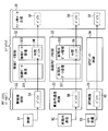
- FIG. 3 is a diagram corresponding to the subsystem layer 20 and the middleware layer 30 in FIG. 2, and the system management unit 21 and the middleware system control unit 31 described above are not shown.
- the wireless device control unit 22 and the wireless data control unit 32 will be described in the order along which the wireless data received by the wireless device 91 is transferred.
- the wireless device control unit 22 is a device driver of the wireless device 91 and receives wireless data input from the wireless device 91. Then, the radio control unit 22 stores the received radio data in the storage area 5A assigned as a buffer for the radio control unit 22 in the RAM 5 (this is referred to as a radio control unit buffer) 5A. This radio control unit buffer 5A is also referred to as a first radio data storage unit. In addition, when wireless data is input from the wireless device 91, the wireless device control unit 22 generates an event indicating that wireless data has been received (referred to as a wireless data reception event) and transmits the event to the task management unit 111. .
- the wireless data control unit 32 includes a wireless data receiving unit 321 and a wireless data management unit 322 as finer functional blocks.
- a storage area of a predetermined size is assigned to the RAM 5 as a buffer for the wireless data control unit 32 (this is an intermediate buffer for wireless data) 5M.
- the wireless data intermediate buffer 5M is also referred to as an intermediate wireless data storage unit.
- the wireless data management unit 322 is configured to virtually include the wireless data intermediate buffer 5M.
- the wireless data management unit 322 virtually includes the wireless data intermediate buffer 5M means that the data stored in the wireless data intermediate buffer 5M is authorized to be deleted. This means that the wireless data management unit 322 has.
- the state where the data can be deleted means that the data may be actually deleted or the storage area storing the data may be overwritten with other data.
- the hardware that actually includes the intermediate buffer 5M for wireless data is the RAM 5.
- a function unit virtually includes a buffer, which means that the function unit has the authority to delete data stored in the buffer. Meaning. In either case, it is the RAM 5 that actually implements the buffer, that is, as hardware.
- the wireless data receiving unit 321 moves the wireless data stored in the wireless device control unit buffer 5A to the wireless data intermediate buffer 5M based on an instruction from the task management unit 111. As a result, the wireless data stored in the wireless device control unit buffer 5A is deleted, and the resources of the wireless device control unit buffer 5A are released. When the wireless data receiving unit 321 has finished moving the wireless data stored in the wireless device control unit buffer 5A to the wireless data intermediate buffer 5M, the wireless data receiving unit 321 generates an event indicating that fact and performs the task management unit 111. Send to.
- the wireless data management unit 322 transfers the wireless data stored in the wireless data intermediate buffer 5M to the wireless data buffer 5P that is virtually included in the application data generation unit 35. , Move it together.
- the wireless data buffer 5P is a storage area allocated as a wireless data buffer used by the application data generation unit 35 in the RAM 5.
- the RAM 5 is a buffer for storing in-vehicle data buffer 5Q, which is a buffer for storing in-vehicle data used by the application data generating unit 35, and GPS data used by the application data generating unit 35.
- a certain GPS data buffer 5R is provided.
- the in-vehicle data buffer 5Q and the GPS data buffer 5R are also virtually provided in the application data generation unit 35.
- These wireless data buffer 5P, in-vehicle data buffer 5Q, and GPS data buffer 5R are also referred to as a second wireless data storage unit, a second in-vehicle data storage unit, and a second separate data storage unit, respectively.
- the wireless data management unit 322 moves the wireless data stored in the wireless data intermediate buffer 5M to the wireless data buffer 5P, the wireless data management unit 322 duplicates the wireless data stored in the wireless data intermediate buffer 5M, The copied data is stored in the wireless data buffer 5P.
- the storage of the duplicated data in the wireless data buffer 5P is completed, the data stored in the wireless data intermediate buffer 5M and overlaid with the other data may be overwritten. Put it in a state.
- to move data, or to move data stored in a certain buffer (providing source) to another buffer (moving destination) means to save the data in the moving destination and to send the data at the providing source.
- in-vehicle communication control unit 23 and the in-vehicle data control unit 33 will be described in this order along the flow of in-vehicle data output from the in-vehicle communication microcomputer 92.
- the in-vehicle communication control unit 23 is a device driver of the in-vehicle communication microcomputer 92 and receives in-vehicle data input from the in-vehicle communication microcomputer 92. Then, the in-vehicle communication control unit 23 stores the received in-vehicle data in the storage area 5B assigned as a buffer for the in-vehicle communication control unit 23 in the RAM 5 (this is used as the in-vehicle communication control unit buffer) 5B. To do.
- This in-vehicle communication control unit buffer 5B is also referred to as a first in-vehicle data storage unit.
- the in-vehicle communication control unit 23 when the in-vehicle data is input from the in-vehicle communication microcomputer 92, the in-vehicle communication control unit 23 generates an event indicating that the in-vehicle data has been received (referred to as an in-vehicle data reception event) It transmits to the task management part 111.
- the in-vehicle data control unit 33 includes an in-vehicle data reception unit 331 and an in-vehicle data management unit 332 as finer functional blocks.
- a storage area of a predetermined size is allocated to the RAM 5 as a buffer 5N for the in-vehicle data control unit 33 (this is an intermediate buffer for in-vehicle data) 5N.
- the in-vehicle data intermediate buffer 5N is virtually provided in the in-vehicle data management unit 332.
- the in-vehicle data intermediate buffer 5N is also referred to as an intermediate in-vehicle data storage unit.
- the in-vehicle data receiving unit 331 moves the in-vehicle data stored in the in-vehicle communication control unit buffer 5B to the in-vehicle data intermediate buffer 5N based on an instruction from the task management unit 111. As a result, the in-vehicle data stored in the in-vehicle communication control unit buffer 5B is deleted, and the resources of the in-vehicle communication control unit buffer 5B are released.
- the in-vehicle data receiving unit 331 generates an event indicating that when the in-vehicle data stored in the in-vehicle communication control unit buffer 5B is transferred to the in-vehicle data intermediate buffer 5N, It transmits to the task management part 111.
- the in-vehicle data management unit 332 is based on an instruction from the task management unit 111, and the in-vehicle data in which the application data generation unit 35 virtually includes the in-vehicle data stored in the in-vehicle data intermediate buffer 5N. Are transferred to the buffer 5Q.
- the in-vehicle data management unit 332 duplicates the in-vehicle data stored in the in-vehicle data intermediate buffer 5N in the same manner as the wireless data management unit 322, and copies the duplicated data into the in-vehicle data buffer 5Q. To store. When the storage of the duplicated data in the in-vehicle data buffer 5Q is completed, the duplication source data stored in the in-vehicle data intermediate buffer 5N is brought into a state where it can be overwritten by other data. .
- the GPS control unit 24 and the GPS data control unit 34 will be described along the flow of GPS data output from the GPS receiver 93.
- the GPS control unit 24 is a device driver of the GPS receiver 93 and receives GPS data output from the GPS receiver 93. Then, the GPS control unit 24 stores the received GPS data in the storage area 5C assigned as a buffer for the GPS control unit 24 in the RAM 5 (this is referred to as a GPS control unit buffer) 5C.
- the GPS control unit 24 when receiving the GPS data from the GPS receiver 93, the GPS control unit 24 generates an event indicating that the GPS data has been received (referred to as a GPS data reception event) and transmits the event to the task management unit 111.
- the GPS control unit 24 is also referred to as another data source control unit.
- GPS data is also referred to as separate data.
- the GPS control unit buffer 5C is also referred to as a first separate data storage unit.
- the GPS data control unit 34 Based on the instruction from the task management unit 111, the GPS data control unit 34 stores the GPS data stored in the GPS control unit buffer 5C in the GPS data buffer 5R that is virtually included in the application data generation unit 35. Transfer. As a result, the GPS data stored in the GPS control unit buffer 5C is deleted, and the resources of the GPS control unit buffer 5C are released.
- the GPS data control unit 34 is also referred to as another data control unit.
- the application data generation unit 35 requires the applications 41 to 43 at a predetermined cycle (referred to as a data generation cycle) based on a plurality of types of data stored in the buffers 5P to R that are virtually included in the application data generation unit 35.
- Data that is, data for application is generated.
- the generated application data is transferred to each of the applications 41 to 43.
- Application data is also referred to as control data.
- the application data generation unit 35 is also referred to as a control data generation unit.
- the data generation cycle varies depending on the application provided in the application layer 40, but is 100 ms as an example here.
- the application data generation unit 35 generates an event (referred to as an application data generation event) that requests generation of application data so that the application data can be generated in the data generation cycle, and the task management unit 111 Output. Then, application data is generated based on an instruction from the task management unit 111.
- various tasks including a task for generating the application data are sequentially executed based on the priority set for each task, as will be described later. For this reason, when there is another task having a relatively high priority, the task for generating the application data is not necessarily performed in a complete data generation cycle.
- Application data is, for example, data indicating the inter-vehicle distance between the preceding vehicle and the host vehicle, host vehicle position data indicating the host vehicle position as latitude and longitude, and the like.
- the host vehicle position data indicates a position calculated by combining GPS data, a moving distance calculated by integrating traveling speed, a traveling direction obtained by integrating angular acceleration, and the like.
- the host vehicle position data may be generated with a cycle shorter than the data generation cycle of other application data in order to ensure the accuracy of the autonomous navigation calculation.
- FIG. 4 is a conceptual diagram showing a storage area realized by the RAM 5, and its memory address is from address 0 to address N (N is an integer).
- the RAM 5 includes various buffers 5A to 5C, 5M to C, and 5P to C.
- the length in the vertical direction is the storage capacity (ie, size) of the buffer. Is conceptually represented. That is, the longer in the vertical direction, the larger the size.
- the buffers are continuously arranged on the storage area.
- the buffers need not be arranged in this way.
- a calculation area used for other purposes may be provided between the buffers.
- the order in which the buffers are arranged is not limited to the order shown in FIG.
- each buffer is only required to be arranged in a different area on the storage area, and their location (address) and order are arbitrary.
- the wireless data buffer 5P, the in-vehicle data buffer 5Q, and the GPS data buffer 5R that are virtually included in the application data generation unit 35 are independent buffers, but some or all of these are summarized. It is good also as a structure provided with a buffer.
- the size of a buffer reserved for a device driver is smaller than a buffer reserved for a program located in a higher layer in a software system such as the middleware layer 30 and the application layer 40.
- the sizes of the wireless device control unit buffer 5A, the in-vehicle communication control unit buffer 5B, and the GPS control unit buffer 5C are reserved for the application data generation unit 35. It is assumed that it is smaller than each of the buffers 5P to C.
- the size of the wireless data intermediate buffer 5M is set based on the data amount per unit time input from the wireless device 91 to the main control unit 1 and the data generation cycle.
- the maximum value of the amount of data input from the wireless device 91 to the main control unit 1 during the two data generation cycles described above that is, 200 ms is used.
- the size of the wireless data intermediate buffer 5M is not limited to this, and it is only necessary to be equal to or larger than the amount of data input from the wireless device 91 to the main control unit 1 during one data generation cycle.
- the assumed maximum value is used as the data amount per unit time input from the wireless device 91 to the main control unit 1, but as another example, an average value determined by various tests or the like. It may be.
- the in-vehicle data intermediate buffer 5N is set based on the data amount per unit time input from the in-vehicle communication microcomputer 92 to the main control unit 1.
- the maximum value of the amount of data input from the in-vehicle communication microcomputer 92 to the main control unit 1 during the two data generation cycles described above (that is, 200 ms) is used. That is, the maximum communication speed between the in-vehicle communication microcomputer 92 and the main control unit 1 is multiplied by a time corresponding to two data generation periods.
- the size of the in-vehicle data intermediate buffer 5N may be other sizes as in the case of the wireless data intermediate buffer 5M.
- the size of the wireless data buffer 5P only needs to be equal to or larger than the size of the wireless data intermediate buffer 5M, and the size of the in-vehicle data buffer 5Q is equal to or larger than the size of the in-vehicle data buffer 5Q. Just do it.
- the size of the GPS data buffer 5R only needs to be equal to or larger than the size of the GPS control unit buffer 5C.
- FIG. 5 shows the priority of the task executed by the functional unit described in the execution unit column.
- these tasks are generated by the task management unit 111.
- the task management unit 111 receives an event from each unit included in the main control unit 1, the task management unit 111 generates a task corresponding to the event.
- the task generation processing performed by the task management unit 111 will be described later with reference to FIG.
- the middleware system control task set with the highest priority is a task for controlling the operation of the entire main control unit 1 and is executed by the middleware system control unit 31.
- each of the units 32 to 35 terminates and discards a task that is being executed or is waiting for execution, so that the power source of the main control unit 1 can be safely shut off.
- the task management unit 111 when receiving an event for terminating the system from the system management unit 21, the task management unit 111 generates a middleware system control task and causes the middleware system control unit 31 to execute the task.
- the middleware system control unit 31 transmits an end notification to each of the units 32 to 35 and 41 to 43 included in the middleware layer 30 and the application layer 40. Upon receiving the end notification, each unit ends or discards the task being executed or waiting for execution. When there is no task being executed or waiting for execution, the middleware system control unit 31 transmits an event to the task management unit 111 indicating that the middleware system control task has been completed. In this way, when the power supply of the main control unit 1 can be safely shut off, the system management unit 21 shuts off the power supply.
- the middleware system control task is basically not executed except when the operation of the main control unit 1 is started and ended, basically only the tasks described below are performed during the operation of the main control unit 1. Executed. That is, the task with the second highest priority is the task that is substantially the highest priority.
- the wireless data receiving unit 321 uses the wireless data stored in the wireless device control unit buffer 5A as the wireless data intermediate unit for the wireless data management unit 322. Move to buffer 5M.
- the in-vehicle data receiving unit 331 virtually stores the in-vehicle data stored in the in-vehicle communication control unit buffer 5B, and the in-vehicle data management unit 332 virtually The vehicle data is moved to the in-vehicle data intermediate buffer 5N.
- the vehicle data management unit 332 moves the vehicle data stored in the vehicle data intermediate buffer 5N to the vehicle data buffer 5Q.
- the GPS data control unit 34 moves the GPS data stored in the GPS control unit buffer 5C to the GPS data buffer 5R.
- the wireless data management unit 322 moves the wireless data stored in the wireless data intermediate buffer 5M to the wireless data buffer 5P.
- the application data generation unit 35 generates application data based on the wireless data, in-vehicle data, and GPS data stored in the buffers 5P to 5R. Provided to the applications 41 to 43.
- step S101 a task corresponding to the received event is generated, and the process proceeds to step S103.
- step S101 for example, when a wireless data reception event is received from the wireless device control unit 22, a wireless data reception task is generated.
- an in-vehicle data reception event is received from the in-vehicle communication control unit 23
- an in-vehicle data reception task is generated.
- a GPS data management task is generated.
- a wireless data management task is generated.
- an in-vehicle data management task is generated.
- an application data generation task is generated.
- step S103 the priority of the task generated in step S101 (assumed to be a new task) is compared with the priority of the task currently being executed. If the priority of the new task is higher than the task being executed, Is YES at step S103, and proceeds to step S105. On the other hand, when the priority of the new task is equal to or lower than the priority of the task being executed, step S103 is NO and the process proceeds to step S107.
- the task management unit 111 in this embodiment selects a task to be executed by using both the priority method and the FCFS (First Com First Service) method.
- the tasks are executed in order from the highest priority, and when there are a plurality of tasks having the same priority, the tasks are executed from the task that has been in the executable state earlier. Even when there is no task currently being executed, step S103 is determined as YES.
- step S105 the task being executed is interrupted, and the new task is put into an execution state (so-called dispatch is performed).
- the interrupted task is put into an executable state, and necessary data is left so that the task can be resumed from the point where it was interrupted later.
- step S107 the new task is set to an executable state.
- step S103 if a task having a higher priority than the suspended task is in an executable state, the task with the higher priority is selected. Executed.
- the wireless data stored in the wireless device control unit buffer 5A is moved to the wireless data intermediate buffer 5M by the wireless data receiving unit 321.
- the in-vehicle data stored in the in-vehicle communication control unit buffer 5B is transferred to the in-vehicle data intermediate buffer 5N by the in-vehicle data receiving unit 331.
- the wireless data reception task is preferentially performed over other processes for transferring various data such as the in-vehicle data reception task and the GPS data management task. That is, the wireless data received by the wireless device control unit 22 is sequentially transferred to the intermediate buffer for wireless data 5M as soon as it is stored in the wireless device control unit buffer 5A.
- the in-vehicle data reception task is performed prior to the wireless data reception task. More specifically, the in-vehicle data reception task is performed with priority over the GPS data management task and the in-vehicle data management task.
- the in-vehicle data received by the in-vehicle communication control unit 23 and stored in the in-vehicle communication control unit buffer 5B is The data is moved to the data intermediate buffer 5N. For this reason, since the in-vehicle communication control unit buffer 5B is also unlikely to become full, an event in which in-vehicle data is discarded due to the in-vehicle communication control unit buffer 5B being full can be suppressed.
- the priority of the wireless data management task is set lower than that of the wireless data reception task, the frequency with which the wireless data management task is executed is relatively low. Accordingly, there is a tendency that the wireless data is accumulated in the wireless data intermediate buffer 5M.
- the size of the wireless data intermediate buffer 5M is based on the amount of data input to the wireless device control unit 22 in the data generation cycle. Therefore, it is unlikely that the wireless data intermediate buffer 5M is full, and the possibility that the wireless data is lost when the wireless data intermediate buffer 5M is full can be reduced.
- the priority of the in-vehicle data management task is set lower than that in the in-vehicle data receiving task, but the size of the in-vehicle data intermediate buffer 5N is input to the in-vehicle communication control unit 23 in the data generation cycle.
- the size is based on the amount of data to be processed. Therefore, the possibility that the in-vehicle data is missed by filling the in-vehicle data intermediate buffer 5N can be reduced.
- both wireless data and in-vehicle data having a larger received data amount per unit time than GPS data are discarded when each buffer becomes full. Fear can be reduced. That is, it is possible to improve the reliability of both wireless data and in-vehicle data communication.
- the following method is also conceivable as another solution technique for reducing the possibility of losing each data when the buffers 5A and 5B are full. That is, the design of the wireless device control unit 22 and the in-vehicle communication control unit 23 is changed so as to secure a larger size of the wireless device control unit buffer 5A and the in-vehicle communication control unit buffer 5B.
- the software adopts a hierarchical structure and a configuration divided into parts for each function, so that it can cope with various applications and can be updated in units of layers or parts.
- the software included in the subsystem layer 20 located in a lower layer can support various applications.
- each of the units 32 and 33 provided in the middleware layer 30 located between the subsystem layer 20 and the application layer 40 is provided with an intermediate buffer according to the application as appropriate. According to such a configuration, since the software at the level of the subsystem layer 20 is not changed, the above-described effects can be achieved without impairing the expandability and updateability of the software.
- the priority of each task is set in descending order: wireless data reception task, in-vehicle data reception task, in-vehicle data management task, GPS data management task, wireless data management task, application data generation task.
- this is not a limitation.
- the priorities are set in descending order: wireless data reception task, wireless data management task, in-vehicle data reception task, in-vehicle data management task, GPS data management task, application data generation task. May be. Further, a wireless data reception task, an in-vehicle data reception task, a wireless data management task, an in-vehicle data management task, a GPS data management task, and an application data generation task may be set in descending order.
- the priority of each task should be higher for the wireless data reception task than for the in-vehicle data reception task and higher for the wireless data reception task than for the wireless data management task.
- the wireless data reception task is set higher than the in-vehicle data reception task
- the in-vehicle data reception task is set higher than the in-vehicle data management task.
- GPS data was illustrated as data used for control processes other than the in-vehicle data indicating the state inside the host vehicle and the wireless data indicating the state around the host vehicle, the physical condition of the user is also included. The data shown may be used. GPS data is not an essential element.
- the main control unit 1 is configured to receive in-vehicle data output from the in-vehicle device via the in-vehicle communication microcomputer 92, but is not limited thereto. It is good also as a structure which inputs in-vehicle data to the main control part 1 directly from each vehicle equipment.
- the in-vehicle device is not limited to the outside of the main control unit 1 but may be a sensor or the like provided inside the casing of the main control unit 1.
Landscapes
- Engineering & Computer Science (AREA)
- Computer Networks & Wireless Communication (AREA)
- Signal Processing (AREA)
- Physics & Mathematics (AREA)
- General Physics & Mathematics (AREA)
- Theoretical Computer Science (AREA)
- Software Systems (AREA)
- General Engineering & Computer Science (AREA)
- Computing Systems (AREA)
- Multimedia (AREA)
- Mechanical Engineering (AREA)
- Medical Informatics (AREA)
- General Health & Medical Sciences (AREA)
- Health & Medical Sciences (AREA)
- Human Computer Interaction (AREA)
- Traffic Control Systems (AREA)
- Communication Control (AREA)
Abstract
無線機制御部用バッファ(5A)に格納されている無線機(91)を介して得られた無線データは、無線データ受信部(321)によって無線データ用中間バッファ(5M)に移される。また、車両内通信制御部用バッファ(5B)に格納されている車両内データは、車両内データ受信部(331)によって車両内データ用中間バッファ(5N)に移される。このとき、無線データ受信タスクは、車両内データ受信タスクなどの、種々のデータを移す他の処理よりも優先的に行われる。すなわち、無線機制御部(22)が受信した無線データは、無線機制御部用バッファ(5A)に格納され次第、逐次無線データ用中間バッファ(5M)に移される為、無線機制御部用バッファ(5A)が無線データで一杯になる可能性を抑制することができる。
Description
本開示は、2013年11月19日に出願された日本出願番号2013-239171号に基づくもので、ここにその記載内容を援用する。
本開示は、車両用の電子制御装置に関する。
近年、車車間通信や路車間通信を実施するための無線機で受信した、他の車両や路側機からのデータ(無線機データあるいは無線データと言及される)に基づいて、種々の制御処理を実施する電子制御装置が提案されている。この種の電子制御装置は、CPU、RAM、ROMなどを備える周知のマイクロコンピュータを主体として構成されており、ROMなどの不揮発性メモリに、種々の制御処理に対応するプログラム(すなわちアプリケーション)が格納されている。
また、この種の電子制御装置には、無線データ以外にも、車両に備えられたセンサや他の電子制御装置等の車両内機器から出力された、車両の状態を示すデータ(車両内データと言及される)が入力される。すなわち、電子制御装置は、無線データ及び車両内データを用いて種々の制御処理を実施する。
例えば特許文献1に開示の電子制御装置は、無線データ及び車両内データを用いて、ユーザの運転操作を支援するための複数の制御処理を実施する。より具体的には、電波メディア受信機(すなわち無線機)が、路側機から送信されたインフラ情報(すなわち、無線データ)を逐次受信し、当該無線データを電子制御装置に逐次出力する。無線データには、例えば、信号の点灯色などを示す信号情報や、対向車の有無などを示す対向車情報、歩行者の有無を示す歩行者情報などを含んでいる。また、電子制御装置は、車両内に構築された車内ネットワークを介して、車両内機器から種々の車両内データを逐次受信する。
電子制御装置は、無線データ及び車両内データから、制御処理に必要なデータ(これを制御データとする)を生成する。そして、電子制御装置は、この生成した制御データとアプリケーションとに基づいて制御処理を実行する。
一般に、マイクロコンピュータはソフトウェアとして、マイクロコンピュータに接続する機器の制御を行う制御部(いわゆるデバイスドライバ)と、種々の制御処理に対応するアプリケーションと、ドライバとアプリケーションとの中間に位置するミドルウェアと、を備える。
前述の制御データを生成するための機能(制御データ生成部とする)は、例えばミドルウェアに設けられる。また、マイクロコンピュータに接続する機器とは、無線機や、車両内機器などを指し、単に接続機器とも称す。
マイクロコンピュータは、接続機器毎に制御部を備えており、具体的には、無線機に対応する無線機制御部、及び車両内機器に対応する車両内通信制御部をそれぞれソフトウェアとして備えている。RAMには、無線機制御部、車両内通信制御部、及び制御データ生成部のそれぞれに対して所定の記憶領域(いわゆるバッファ)が割り当てられており、順に、無線機制御部用バッファ、車両内通信制御部用バッファ、データ生成部用バッファとする。
各制御部は、自身に対応する接続機器からデータが入力されると、その入力されたデータを、その制御部用に確保されているバッファにいったん格納して保持する。制御データ生成部は、各制御部のバッファに保持されているデータを、所定の周期又はタイミングで、制御データ生成部用に確保されているデータ生成部用バッファに移し、制御データを生成する。
ここで、無線機制御部用バッファや車両内通信制御部用バッファなど、デバイスドライバ用に確保されるバッファのサイズは、一般的に、ミドルウェアやアプリケーションのために確保されるバッファのサイズよりも小さい。また、車車通信や路車間通信によって得られるデータである無線データは、様々な情報を含むため、1回の通信で受信するデータのサイズは、無線機制御部用バッファのサイズに対して大きい。このため、制御データ生成部が、無線機制御部用バッファに格納されているデータを移すことによって当該バッファを解放するまでに、無線機制御部用バッファが無線データで一杯になってしまう恐れがある。
また、車両内データのサイズは無線データほど大きくはないが、車両内データを受信する頻度は相対的に多いため、やはり車両内通信制御部用バッファもまた、車両内データで一杯になりやすい。
各制御部は、自身に対応するバッファが一杯になっている場合には、接続機器からのデータが入力されてもその新規データを保存することが出来ない為、その新たに受信したデータを破棄することになる。もちろん、新たに受信したデータを破棄してしまうと、当該データに含まれる内容が制御データに反映されなくなってしまうため、データを破棄することは避けたい。
特に、無線データは動的に変化する通信相手から受信するデータであるため、以降において再び同じデータを取得できる保証はなく、当該無線データを破棄することはできるだけ避けたいという要求があった。
本開示の目的は、無線機制御部用のバッファが一杯になることに起因する無線機を介して得られた無線データの取りこぼしが生じる可能性を低減する電子制御装置を提供することにある。
上記の目的を達成するため、本開示の一つの例によれば、電子制御装置は、次のように提供される。電子装置は、車両に搭載され、別車両又は路側機の少なくとも何れか一方と無線通信を実施する無線機が受信した無線データと、車両内に備えられている車両内機器で生成された車両内データと、に基づいた制御処理を実施する。電子装置は、無線機から入力される無線データを第1無線データ記憶部に格納する無線機制御部と、車両内機器から入力される車両内データを第1車両内データ記憶部に格納する車両内通信制御部と、第1無線データ記憶部に格納されている無線データを第2無線データ記憶部に格納する無線データ制御部と、第1車両内データ記憶部に格納されている車両内データを第2車両内データ記憶部に格納する車両内データ制御部と、第2無線データ記憶部に格納されている無線データ、及び第2車両内データ記憶部に格納されている車両内データから、制御処理を実施するために必要なデータである制御データを生成する制御データ生成部と、を備える。無線データ制御部は、さらに、第1無線データ記憶部に格納されている無線データを中間無線データ記憶部に移す無線データ受信部と、中間無線データ記憶部に格納されている無線データを、第2無線データ記憶部に移す無線データ管理部と、を備える。車両内データ制御部は、さらに、第1車両内データ記憶部に格納されている車両内データを、中間車両内データ記憶部に移す車両内データ受信部を備え、無線データ受信部による処理を、車両内データ受信部による処理よりも優先し、かつ、無線データ受信部による処理を、無線データ管理部による処理よりも優先する。
以上の構成では、第1無線データ記憶部に格納されている無線データは、無線データ受信部によって中間無線データ記憶部に移される。また、第1車両内データに格納されている車両内データは、車両内データ受信部によって中間車両内データ記憶部に移される。このとき、無線データ受信部が実施する処理は、車両内データ受信部が実施する処理や、無線データ管理部が実施する処理よりも、優先的に行われる。すなわち、第1無線データ記憶部に格納されている無線データを中間無線データ記憶部に移す処理は、他の処理よりも優先して行われる。
したがって、以上の構成によれば、第1無線データ記憶部が無線データで一杯になる可能性を抑制することができる。言い換えれば、無線機制御部用のバッファ(すなわち第1無線データ記憶部)が一杯になることに起因する無線データの取りこぼしが生じる可能性を低減することができる。
また、車両内データも、第1車両内データから中間車両内データ記憶部に順次移される。このため、車両内通信制御部用のバッファも一杯になりにくいため、車両内データの取りこぼしも抑制することが出来る。
本開示についての上記目的およびその他の目的、特徴や利点は、添付の図面を参照しながら下記の詳細な記述により、より明確になる。
本実施形態に係る電子制御システムの概略的な構成の一例を示すブロック図
本実施形態に係る主制御部の概略的なソフトウェア構成の一例を示すブロック図
無線データ、車両内データ、GPSデータの流れを説明するための図
RAMに割り当てられているバッファの構成を概念的に示すブロック図
各タスクに設定される優先度の一例を示す図
タスク管理部が実施するタスク生成処理の流れを示すフローチャート図
以下、本開示の実施形態の一例について図を用いて説明する。図1は、本実施形態における車両(ホスト車両とも言及される)に搭載される電子制御システム100の概略的な構成の一例を示す図である。図1に示すように電子制御システム100は、主制御部1と、種々のデータソース9としての、無線機91、車両内通信マイクロコンピュータ92、及びGPS受信機93を備える。
これら無線機91、車両内通信マイクロコンピュータ92、及びGPS受信機93と主制御部1とは、それぞれ相互通信可能に接続されている。なお、データソース9は、後述する無線データ及び車両内データが主制御部1に入力される構成となっていれば良く、データソース9の数や機器の種類、回路構成などは任意である。主制御部1は、電子制御装置とも言及される。
無線機91は、例えば車車間通信および路車間通信の両方、またはいずれか一方を行う無線通信装置であり、無線機91が備える受信アンテナで受信したデータ(無線データとする)を、主制御部1に出力する。無線データには、車車間通信によって別車両から受信したデータである車車受信データと、路車間通信によって路側機から受信したデータである路車受信データがある。なお、車車間通信及び路車間通信はいずれも同報通信方式で実施される。
車車受信データは、送信元となる車両を他の車両と識別するための送信元車両識別番号や、宛先となる車両を他の車両と識別するための宛先車両識別番号、送信元となる車両の車両状態を表す車両状態情報、などを含んでいる。車両状態情報としては、例えば送信元の車両の、現在位置、走行速度、進行方向、ウィンカースイッチのオン/オフ、ブレーキランプの点灯状態などを含んでいる。すなわち、車車受信データには、当該データを送信した他の車両に関する様々な情報を含まれている。
路車受信データは、路側機が生成するデータであってもよいし、路側機の通信エリア内に存在する他の車両が送信したデータであってもよい。後者のように車両と車両が路側機を介して行う通信は、いわゆる車路車通信ともいう。車路車通信を実施する路側機から取得する路車受信データは、前述の車車受信データと同様の内容を含んでいる。
車路車通信でなく、路側機が生成するデータの内容としては、路側機周辺の交通状況を表す交通状況データなどである。交通状況データとは、例えば、渋滞情報や、路側機周辺において運転者の死角となる領域の車両、歩行者、障害物などの存在の有無などを表す。ここで、路側機周辺とは、路側機の位置を基準として適宜設計される範囲であればよい。例えば歩行者の有無を交通状況データとする場合には、20m圏内とすればよい。このように路車受信データもまた、路側機周辺に存在する車両や、路側機周辺の交通状況データなど、様々な情報を備えている。
以上で述べたように、無線機91は、車車受信データ又は路車受信データを受信すると、その受信データを無線データとして逐次主制御部1に出力する。ここで、無線機91から主制御部1に無線データが出力される頻度は、ホスト車両周辺に存在し、ホスト車両と車々間通信を実施する別車両(これを周辺車両とも言及する)の数や、ホスト車両と路車間通信を実施する路側機の数によって異なる。ただし、無線データには上述したように様々な情報が含まれているため、1つのデータのサイズは後述するGPSデータなどに比べて大きく、100Byteから最大1000Byteに達する場合もある。
なお、上述したホスト車両周辺とは、無線機91が形成する通信エリアを指し、例えばホスト車両の前方200m、後方100m、両側方100mとする。また、周辺車両及び路側機は、それぞれ所定の送信周期(例えば100ms毎)で車車受信データ及び路車受信データを送信する。無線機91は、最大P台の他車両、及び最大Q台の路側機のそれぞれから無線データを受信する性能を備えるとすると、無線機91は、1つの送信周期の間に、最大P+Q台の送信元から送信されたデータを受信することになる。一例としてP=200、Q=8とすると、100msの間に208台の送信元から受信した車車受信データ及び路車受信データを受信し、これらを逐次主制御部1に出力する。
車両内通信マイクロコンピュータ92は、周知のマイクロコンピュータであって、車両に備えられている他のECUやセンサ(これらを車載機器とする)と、相互通信可能に接続されている。そして、これら車載機器から取得するデータ(これを車両内データとする)を、逐次主制御部1に出力する。
例えば、車載機器は、周知の車速センサ、加速度センサ、ジャイロセンサ、操舵角センサ、ブレーキセンサ、シフトポジションセンサ、ボディECU、操舵ECUなどがある(何れも図示略)。操舵角センサは、ステアリングホイールの回転角(すなわち操舵角)を検出する。ボディECUは、ドアの施解錠などを制御し、操舵ECUは、図示しない電動パワーステアリング装置を駆動させることで操舵角や操舵反力を制御する。
車両内データは、各車載機器から出力されるものであって、例えば、走行速度や、Gセンサが検出する加速度、ジャイロセンサが検出する回転角速度、ブレーキセンサが検出するブレーキペダルの踏み込み量、ウィンカースイッチのオン/オフなどがある。すなわち、車両内データは、車両内機器で生成された、ホスト車両の状態を表すデータである。
車両内通信マイクロコンピュータ92と主制御部1との通信速度はこれらを接続するネットワークの規定にもよるが、例えば512kbpsである。また、車両内通信マイクロコンピュータ92は、様々な車載機器から非同期で送信されるデータを取得する。したがって、主制御部1が車両内通信マイクロコンピュータ92から車両内データを受信する間隔は短く、単位時間当りに受信するデータ量は相対的に大きい。
GPS受信機93は、GPS(Global Positioning System)で用いられる衛星から送信されるGPS電波を受信することで自装置の現在位置を示すデータ(GPSデータとする)を取得する。現在位置は例えば緯度及び経度で表される。もちろん、GPS受信機93に代わって、GNSS(Global Navigation Satellite System)で用いられる衛星からの電波を受信することで現在位置を示すデータを取得するGNSS受信機を備えていても良い。
なお、GPS受信機93がGPS電波を受信する周期は、例えば100ms程度であって、そのデータのサイズも無線データほど大きくない。したがって、GPS受信機93から主制御部1に入力される単位時間当りのデータ量は、無線機91や車両内通信マイクロコンピュータ92から入力される単位時間当りのデータ量よりも小さい。
主制御部1は、周知のマイクロコンピュータであって、データソース9から入力されるデータと、予め定められたアプリケーションソフトウェア(以降、単にアプリケーション)に基づいて、ホスト車両に搭載される電子機器の制御処理を実施する。
主制御部1が実施する制御処理としては、例えば、公知のACC(Adaptive Cruise Control)や、衝突被害軽減ブレーキ機能、レーンキープアシスト(LKA:Lane Keeping Assist)などがある。ACCでは、先行車との距離に基づいて、車間距離を一定に保つように、駆動系及び制動系のシステムを制御する。また、LKAを実施する場合には、操舵ECUに、制御の目標値とする操舵角や操舵量などを出力する。
主制御部1のハードウェア構成としては、図1に示されるように、CPU2、フラッシュメモリ3、ROM4、RAM5、入出力ポート(I/0ポートとする)7、及びそれらを接続するバス6を備えている。データソース9から出力された信号は、I/Oポート7を介して入力される。なお、I/Oポート7は、シリアル入出力ポート、パラレル入出力ポート、ビット入出力ポート、アナログ入出力ポートなど、種々のデータの種類や通信形式に応じたポートを備えている。
なお、本実施形態において主制御部1は、1つのCPUを備える構成(いわゆるシングルコア)とする。もちろん、主制御部1は、複数のCPUを備えていても良いが、その場合、本実施形態で言及する処理は何れか1つのCPUで行うものとする。
フラッシュメモリ3は、書き換え可能な不揮発性メモリであって、オペレーションシステム(以降、OS:Operating System)11などの種々のソフトウェアを記憶している。これらフラッシュメモリ3に格納されているソフトウェアの構成については、図2を用いて後述する。
ROM4には、例えば主制御部1の起動時にOSをロードするためのプログラムが格納されており、いわゆるブートROMとしての役割を担う。もちろん、他の例として、フラッシュメモリ3に格納されているソフトウェアの一部または全部は、このROM4に格納されていても良い。
RAM5は、フラッシュメモリ3に格納された各プログラムに基づいてCPU2が実行する各種演算のための作業領域として用いられ、プログラム毎に個別に割り当てられた記憶領域を備えている。また、後述する種々のバッファメモリ(以降、バッファ)5A~C、5M~C、5M~Cも、このRAM5が備えている。
また、主制御部1が備えるソフトウェアの構成について図2を用いて説明する。図2に示すようにフラッシュメモリ3に格納されるソフトウェアは、システム層10、サブシステム層20、ミドルウェア層30、アプリケーション層40からなる階層構造を有している。なお、ここではシステム層10とサブシステム層20とを区別しているが、サブシステム層20も纏めてシステム層10とみなしてもよい。
システム層10には、OS11が格納されている。このOS11は、周知のリアルタイムOSであって、以下で説明する各部21~24、31~35、41~43が実施する処理(すなわち、タスク)の管理や、RAMなどのメモリ資源の管理などを行う。タスク管理とは、例えば、タスクの生成や、実行させるタスクの選択、割りこみ処理、中断処理などを指す。OS11によって実現される種々の機能のうち、このタスク管理を実行する機能をタスク管理部111とする。
タスク管理部111は、各タスクに予め設定されている優先度に基づいて、実行させるタスクを決定する、いわゆる優先度方式のタスク管理を行う。なお、各タスクの優先度やタスク管理部111の作動については、図5及び図6を用いて後述する。
この他、OS11は、コンピュータ間の通信の管理する機能や、主制御部1に障害が発生した場合にその障害状態から復旧する機能、複数のタスクから同じ入出力装置に対し、データの要求があった場合に、データ入出力の調停を行う機能などを実現する。
サブシステム層20は、主制御部1に供給される電力の遮断処理などを管理するシステム管理部21の他、主制御部1に接続するデータソース9に応じた種々のデバイスドライバを備えている。より具体的には、無線機91のデバイスドライバである無線機制御部22、車両内通信マイクロコンピュータ92のデバイスドライバである車両内通信制御部23、及びGPS受信機93のデバイスドライバであるGPS制御部24を備えている。無線機制御部22、車両内通信制御部23、及びGPS制御部24の詳細な作動については、図3を用いて後述する。
ミドルウェア層30は、サブシステム層20とアプリケーション層40間の中間に位置するものであって、データソース9のそれぞれから入力される種々のデータを、アプリケーション層40が備える各アプリケーション41~43に渡す役割を担う。より具体的に、ミドルウェア層30は、ミドルウェアシステム制御部31、無線データ制御部32、車両内データ制御部33、GPSデータ制御部34、アプリ用データ生成部35を備えている。このうち、ミドルウェアシステム制御部31は、ミドルウェア層30に備えられている各部32~35を制御する。無線データ制御部32、車両内データ制御部33、GPSデータ制御部34、アプリ用データ生成部35については、図3を用いて説明する。
アプリケーション層40は、前述のACCや、衝突被害軽減ブレーキ機能など、種々の制御処理を実現するためのソフトウェア、すなわちアプリケーションを備えている。例えば、ACCを実現するためのアプリケーション41、衝突被害軽減ブレーキ機能を実現するためのアプリケーション42、LKAを実現するためのアプリケーション43などを備える。なお、以上では、より安全な走行を実現するためアプリケーションを主制御部1が備えるアプリケーションとして例示したが、その他、燃費やバッテリー消費を低減するためのアプリケーションなどであってもよい。こうしたアプリケーションの数や種類は任意である。
次に、図3を用いて、無線機制御部22、車両内通信制御部23、及びGPS制御部24、無線データ制御部32、車両内データ制御部33、GPSデータ制御部34、アプリ用データ生成部35について説明する。図3は、図2のサブシステム層20とミドルウェア層30に対応する図であって、先に説明したシステム管理部21及びミドルウェアシステム制御部31については、図示を省略している。
まず、無線機91が受信した無線データが渡されていく流れに沿って、無線機制御部22、無線データ制御部32の順に説明する。
無線機制御部22は、無線機91のデバイスドライバであって、無線機91から入力される無線データを受信する。そして、無線機制御部22は、受信した無線データを、RAM5において無線機制御部22用のバッファとして割り当てられた記憶領域(これを無線機制御部用バッファとする)5Aに格納する。この無線機制御部用バッファ5Aは第1無線データ記憶部とも言及される。また、無線機制御部22は、無線データを無線機91から入力されると、無線データを受信した旨を表すイベント(無線データ受信イベントとする)を生成して、タスク管理部111に送信する。
無線データ制御部32は、より細かい機能ブロックとして、無線データ受信部321と無線データ管理部322を備える。また、RAM5には、無線データ制御部32用のバッファ(これを無線データ用中間バッファとする)5Mとして、所定のサイズの記憶領域が割り当てられている。この無線データ用中間バッファ5Mは中間無線データ記憶部とも言及される。本実施形態では図3に示すように、無線データ管理部322が、この無線データ用中間バッファ5Mを仮想的に備える構成とする。
なお、ここでの無線データ管理部322が無線データ用中間バッファ5Mを仮想的に備える、とは、無線データ用中間バッファ5Mに格納されているデータを、削除しても良い状態にする権限を無線データ管理部322が有する、という意味である。削除してもよい状態にする、とは、実際に削除してもよいし、そのデータが格納されている記憶領域を、他のデータによって上書きしてもよい状態にすることを指す。もちろん、無線データ用中間バッファ5Mを実際に備えるハードウェアはRAM5である。
以降においても、或る機能部が或るバッファを仮想的に備える、とは、その機能部がそのバッファに格納されているデータを削除しても良い状態にする権限を有している、という意味である。いずれの場合にも、そのバッファを実際に、すなわちハードウェアとして、実現しているのはRAM5である。
無線データ受信部321は、タスク管理部111からの指示に基づいて、無線機制御部用バッファ5Aに格納されている無線データを、無線データ用中間バッファ5Mに移す。これによって、無線機制御部用バッファ5Aに格納されていた当該無線データは削除され、無線機制御部用バッファ5Aのリソースが解放される。なお、無線データ受信部321は、無線機制御部用バッファ5Aに格納されている無線データを、無線データ用中間バッファ5Mに移し終えると、その旨を示すイベントを生成して、タスク管理部111に送信する。
無線データ管理部322は、タスク管理部111からの指示に基づいて、無線データ用中間バッファ5Mに格納されている無線データを、アプリ用データ生成部35が仮想的に備える無線データ用バッファ5Pに、纏めて移す。この無線データ用バッファ5Pは、RAM5においてアプリ用データ生成部35が用いる無線データ用のバッファとして割り当てられた記憶領域である。
なお、RAM5には、アプリ用データ生成部35が用いる車両内データを格納するためのバッファである車両内データ用バッファ5Q、及びアプリ用データ生成部35が用いるGPSデータを格納するためのバッファであるGPSデータ用バッファ5Rが設けられている。これら車両内データ用バッファ5Q、及びGPSデータ用バッファ5Rもまた、仮想的にアプリ用データ生成部35が備えている。これら無線データ用バッファ5P、車両内データ用バッファ5Q、GPSデータ用バッファ5Rは、それぞれ第2無線データ記憶部、第2車両内データ記憶部、第2別データ記憶部とも言及される。
また、無線データ管理部322は、無線データ用中間バッファ5Mに格納されている無線データを、無線データ用バッファ5Pに移す際、無線データ用中間バッファ5Mに格納されている無線データを複製し、その複製したデータを無線データ用バッファ5Pに格納する。そして、この複製したデータの無線データ用バッファ5Pへの格納が完了すると、無線データ用中間バッファ5Mに格納されてあって、複製の元となったデータを、他のデータによって上書きされても良い状態にする。
本実施形態では、このようにデータの提供先に格納したデータと同じデータが、データの提供元に残っている場合であっても、その提供元に残っているデータを他のデータで上書きしても良い状態にする場合には、データを移す、と表現する。もちろん、本来の、提供先へデータを格納した時に提供元の当該データを削除する場合も、データを移すという意味に含まれる。
すなわち、データを移す、あるいは、或るバッファ(提供元)に保存されているデータを他のバッファ(移動先)に移す、とは、そのデータを移動先に保存するとともに、提供元においてそのデータを保存していた記憶領域を自由に使えるようにする(すなわちリソースの解放)という意味である。
次に、車両内通信マイクロコンピュータ92から出力される車両内データの流れに沿って、車両内通信制御部23、車両内データ制御部33の順に説明する。
車両内通信制御部23は、車両内通信マイクロコンピュータ92のデバイスドライバであって、車両内通信マイクロコンピュータ92から入力される車両内データを受信する。そして、車両内通信制御部23は、受信した車両内データを、RAM5において車両内通信制御部23用のバッファとして割り当てられた記憶領域(これを車両内通信制御部用バッファとする)5Bに格納する。この車両内通信制御部用バッファ5Bは第1車両内データ記憶部とも言及される。また、車両内通信制御部23は、車両内データが車両内通信マイクロコンピュータ92から入力されると、車両内データを受信した旨を表すイベント(車両内データ受信イベントとする)を生成して、タスク管理部111に送信する。
車両内データ制御部33は、より細かい機能ブロックとして、車両内データ受信部331及び車両内データ管理部332を備える。また、RAM5には、車両内データ制御部33用のバッファ(これを車両内データ用中間バッファとする)5Nとして、所定のサイズの記憶領域が割り当てられている。この車両内データ用中間バッファ5Nは、車両内データ管理部332が仮想的に備えている。車両内データ用中間バッファ5Nは中間車両内データ記憶部とも言及される。
車両内データ受信部331は、タスク管理部111からの指示に基づいて、車両内通信制御部用バッファ5Bに格納されている車両内データを、車両内データ用中間バッファ5Nに移す。これによって、車両内通信制御部用バッファ5Bに格納されていた当該車両内データは削除され、車両内通信制御部用バッファ5Bのリソースが解放される。なお、車両内データ受信部331は、車両内通信制御部用バッファ5Bに格納されている車両内データを、車両内データ用中間バッファ5Nに移し終えると、その旨を示すイベントを生成して、タスク管理部111に送信する。
車両内データ管理部332は、タスク管理部111からの指示に基づいて、車両内データ用中間バッファ5Nに格納されている車両内データを、アプリ用データ生成部35が仮想的に備える車両内データ用バッファ5Qに纏めて移す。
このとき、車両内データ管理部332は、無線データ管理部322と同様に、車両内データ用中間バッファ5Nに格納されている車両内データを複製し、その複製したデータを車両内データ用バッファ5Qに格納する。そして、この複製したデータの車両内データ用バッファ5Qへの保存が完了すると、車両内データ用中間バッファ5Nに格納されてある複製元のデータを、他のデータによって上書きされても良い状態にする。
また、GPS受信機93から出力されるGPSデータの流れに沿って、GPS制御部24、GPSデータ制御部34について説明する。
GPS制御部24は、GPS受信機93のデバイスドライバであって、GPS受信機93から出力されるGPSデータを受信する。そして、GPS制御部24は、受信したGPSデータを、RAM5においてGPS制御部24用のバッファとして割り当てられた記憶領域(これをGPS制御部用バッファとする)5Cに格納する。
また、GPS制御部24は、GPSデータをGPS受信機93から受信すると、GPSデータを受信した旨を表すイベント(GPSデータ受信イベントとする)を生成して、タスク管理部111に送信する。このGPS制御部24は別データソース制御部とも言及される。GPSデータは別データとも言及される。GPS制御部用バッファ5Cは第1別データ記憶部とも言及される。
GPSデータ制御部34は、タスク管理部111からの指示に基づいて、GPS制御部用バッファ5Cに格納されているGPSデータを、アプリ用データ生成部35が仮想的に備えるGPSデータ用バッファ5Rに移す。これによって、GPS制御部用バッファ5Cに格納されていた当該GPSデータは削除され、GPS制御部用バッファ5Cのリソースが解放される。このGPSデータ制御部34は別データ制御部とも言及される。
アプリ用データ生成部35は、自身が仮想的に備えるバッファ5P~Rに格納されている複数種別のデータに基づいて、所定の周期(データ生成周期とする)で、アプリケーション41~43が必要とするデータ、すなわちアプリ用データを生成する。生成されたアプリ用データは各アプリケーション41~43へ渡される。アプリ用データは制御データとも言及される。アプリ用データ生成部35は制御データ生成部とも言及される。
データ生成周期は、アプリケーション層40に備えられるアプリケーションによって異なるが、ここでは一例として100msとする。アプリ用データ生成部35は、データ生成周期でアプリ用データを生成できるように、アプリ用データを生成することを要求するイベント(アプリ用データ生成イベントとする)を生成してタスク管理部111に出力する。そして、タスク管理部111からの指示に基づいて、アプリ用データの生成を実施する。
なお、このアプリ用データを生成するタスク(アプリ用データ生成タスクとする)も含めて種々のタスクは、後述するように、各タスクに設定される優先度に基づいて順次実行される。このため、優先度が相対的に高い他のタスクが存在する場合には、アプリ用データを生成するタスクは、完全なデータ生成周期で実施されるとは限らない。
アプリ用データは、例えば、先行車両とホスト車両との車間距離を示すデータや、ホスト車位置を緯度及び経度を示すホスト車位置データなどである。例えば、ホスト車位置データは、GPSデータ、走行速度を積分して算出される移動距離、角加速度を積分して得られる進行方向などを組み合わせて算出される位置を示す。なお、ホスト車位置データに関しては、自律航法演算の精度を確保するために、他のアプリ用データのデータ生成周期よりも短い周期で生成されてもよい。
ここで、図4を用いてRAM5内に設けられる各バッファについて述べる。図4はRAM5によって実現される記憶領域を表した概念図であって、そのメモリアドレスは0番地からN番地(Nは整数)までとする。上述したようにRAM5は、種々のバッファ5A~C、5M~C、5P~Cを備えており、各バッファを示す記憶領域において、縦方向の長さが、そのバッファの記憶容量(すなわちサイズ)を概念的に表している。すなわち、縦方向に長いほど、サイズが大きいことを示す。
なお、図4においては、各バッファを記憶領域上において連続して配置しているが、このように連続した配置となっていなくてもよい。例えば、各バッファの間に他の用途に用いられる演算領域が設けられていても良い。また、各バッファを配置する順番も図4に示す順番に限らない。
すなわち、記憶領域上において各バッファはそれぞれ異なる領域に配置されていればよく、それらの場所(アドレス)や順番は任意である。また、ここでは、アプリ用データ生成部35が仮想的に備える無線データ用バッファ5P、車両内データ用バッファ5Q、GPSデータ用バッファ5Rを独立したバッファとしているが、これら一部又は全部を纏めたバッファを備える構成としてもよい。
一般的に、デバイスドライバ用に確保されるバッファのサイズは、ミドルウェア層30やアプリケーション層40など、ソフトウェアシステムにおいて、より上層に位置するプログラム用に確保されるバッファよりも小さい。図4に示すように本実施形態においても、無線機制御部用バッファ5A、車両内通信制御部用バッファ5B、GPS制御部用バッファ5Cのサイズは、アプリ用データ生成部35用に確保される各バッファ5P~Cよりも小さいものとする。
無線データ用中間バッファ5Mのサイズは、無線機91から主制御部1に入力される単位時間当りのデータ量と、データ生成周期と、に基づいて設定される。本実施形態では、一例として、上述したデータ生成周期の2周期分(すなわち200ms)の間に無線機91から主制御部1に入力されるデータ量の最大値とする。
もちろん、無線データ用中間バッファ5Mのサイズは、これに限らず、データ生成周期1回分の間に無線機91から主制御部1に入力されるデータ量以上となっていればよい。なお、無線機91から主制御部1に入力される単位時間当りのデータ量は、本実施形態では、その想定される最大値を用いるが、他の例として、種々の試験などによって定まる平均値などであってもよい。
車両内データ用中間バッファ5Nは、車両内通信マイクロコンピュータ92から主制御部1に入力される単位時間当りのデータ量に基づいて設定される。本実施形態では、一例として、上述したデータ生成周期の2周期分(すなわち200ms)の間に車両内通信マイクロコンピュータ92から主制御部1に入力されるデータ量の最大値とする。すなわち、車両内通信マイクロコンピュータ92と主制御部1との間の通信速度の最大通信速度にデータ生成周期の2周期分の時間を乗算した値とする。もちろん、車両内データ用中間バッファ5Nのサイズも、無線データ用中間バッファ5Mと同様に、他のサイズとしてもよい。
無線データ用バッファ5Pのサイズは、無線データ用中間バッファ5Mのサイズ以上となっていればよく、また、車両内データ用のバッファ5Qのサイズは、車両内データ用バッファ5Qのサイズ以上となっていればよい。また、GPSデータ用バッファ5Rのサイズは、GPS制御部用バッファ5Cのサイズ以上となっていればよい。
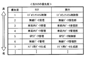
次に、ミドルウェア層30が備える各部31~35が実行するタスクに設定されている優先度について、図5を用いて説明する。図5は、実行部の欄に記載されている機能部が実行するタスクの優先度を示しており、優先度の欄の数字が小さいほど、すなわち表においてより上部に配置されているほど、優先度が高いことを表す。なお、これらのタスクは、タスク管理部111によって生成される。タスク管理部111は、主制御部1が備える各部からイベントを受信すると、そのイベントに応じたタスクを生成する。このタスク管理部111が実施するタスク生成時の処理については、図6を用いて後述する。
最も優先度が高く設定されているミドルウェアシステム制御タスクは、主制御部1全体の動作を制御するタスクであって、ミドルウェアシステム制御部31によって実行される。ミドルウェアシステム制御タスクでは、例えば、各部32~35が実行中又は実行待機中のタスクを終了及び破棄させ、主制御部1の電源を安全に遮断できる状態にする。
例えば、タスク管理部111は、システム管理部21からシステムを終了させる旨のイベントを受信した場合に、ミドルウェアシステム制御タスクを生成し、当該タスクをミドルウェアシステム制御部31に実行させる。
ミドルウェアシステム制御部31は、ミドルウェア層30及びアプリケーション層40が備える各部32~35、41~43に、終了通知を送信する。各部は、終了通知を受信すると実行中又は実行待機中のタスクを終了又は破棄する。そして、実行中及び実行待機中のタスクがいずれも無くなると、ミドルウェアシステム制御部31は、ミドルウェアシステム制御タスクが完了した旨のイベントをタスク管理部111に送信する。このようにして、主制御部1の電源を安全に遮断できる状態になると、システム管理部21が電源を遮断させる。
なお、ミドルウェアシステム制御タスクは、基本的に主制御部1の動作を開始する時と終了する時以外は実行されない為、主制御部1の動作中においては、基本的に以降で述べるタスクのみが実行される。すなわち、優先度が2番目のタスクが実質的に最優先されるタスクとなる。
優先度が2番目に高い無線データ受信タスクでは、無線データ受信部321が、無線機制御部用バッファ5Aに格納されている無線データを、無線データ管理部322が仮想的に備える無線データ用中間バッファ5Mに移す。優先度が3番目に高い車両内データ受信タスクでは、車両内データ受信部331が、車両内通信制御部用バッファ5Bに格納されている車両内データを、車両内データ管理部332が仮想的に備える車両内データ用中間バッファ5Nに移す。
優先度が4番目である車両内データ管理タスクでは、車両内データ管理部332が、車両内データ用中間バッファ5Nに格納されている車両内データを車両内データ用バッファ5Qに移す。優先度が5番目であるGPSデータ管理タスクでは、GPSデータ制御部34が、GPS制御部用バッファ5Cに格納されているGPSデータを、GPSデータ用バッファ5Rに移す。
優先度が6番目である無線データ管理タスクでは、無線データ管理部322が、無線データ用中間バッファ5Mに格納されている無線データを、無線データ用バッファ5Pに移す。優先度が7番目であるアプリ用データ生成タスクでは、アプリ用データ生成部35が、バッファ5P~5Rに格納されている無線データ、車両内データ、GPSデータに基づいて、アプリ用データを生成して、アプリケーション41~43に提供する。
次に、図6に示すフローチャートを用いて、タスク管理部111が実施するタスク生成処理の流れについて説明する。このフローチャートは、タスク管理部111がイベントを受信した時に開始される。
まず、ステップS101では、受信したイベントに応じたタスクを生成してステップS103に移る。このステップS101では、例えば、無線機制御部22から無線データ受信イベントを受信した場合には、無線データ受信タスクを生成する。車両内通信制御部23から車両内データ受信イベントを受信した場合には、車両内データ受信タスクを生成する。GPS制御部24からGPSデータ受信イベントを受信した場合には、GPSデータ管理タスクを生成する。
また、無線データ受信タスクが完了したことを示すイベントを受信した場合には、無線データ管理タスクを生成する。車両内データ受信タスクが完了したことを示すイベントを受信した場合には、車両内データ管理タスクを生成する。さらに、アプリ用データ生成イベントを受信した場合には、アプリ用データ生成タスクを生成する。
ステップS103では、ステップS101で生成したタスク(新規タスクとする)の優先度と、現在実行中のタスクの優先度とを比較し、新規タスクのほうが、実行中タスクよりも優先度が高い場合には、ステップS103がYESとなってステップS105に移る。一方、新規タスクの優先度が、実行中タスクの優先度以下である場合には、ステップS103がNOとなってステップS107に移る。
このように本実施形態におけるタスク管理部111は、優先度方式とFCFS(First Come First Service)方式を併用して、実行させるタスクを選択するものとする。すなわち、優先度の高いものから順次実行させるとともに、優先度が等しいタスクが複数ある場合には、より先に実行可能状態となったタスクから実行させる。なお、現在実行中のタスクが無い場合にもステップS103はYESと判定する。
ステップS105では、実行中タスクを中断させ、新規タスクを実行状態とする(いわゆるディスパッチを実施する)。中断されたタスクは、実行可能状態とし、後で中断したところから当該タスクを再開できるように必要なデータは残しておく。ステップS107では、新規タスクを実行可能状態に設定する。
そして、実行中タスクが終了すると、実行可能状態となっているタスクの中で最も優先度が高いタスクを実行させる。このとき、ステップS103で中断されていたタスクがある場合でも、その中断されているタスクよりも優先度が高いタスクが実行可能状態となっている場合には、その優先度が高いほうのタスクが実行される。
(実施形態のまとめ)
以上のような構成では、無線機制御部用バッファ5Aに格納されている無線データは、無線データ受信部321によって無線データ用中間バッファ5Mに移される。また、車両内通信制御部用バッファ5Bに格納されている車両内データは、車両内データ受信部331によって車両内データ用中間バッファ5Nに移される。
以上のような構成では、無線機制御部用バッファ5Aに格納されている無線データは、無線データ受信部321によって無線データ用中間バッファ5Mに移される。また、車両内通信制御部用バッファ5Bに格納されている車両内データは、車両内データ受信部331によって車両内データ用中間バッファ5Nに移される。
このとき、無線データ受信タスクは、車両内データ受信タスクや、GPSデータ管理タスクなどの、種々のデータを移す他の処理よりも優先的に行われる。すなわち、無線機制御部22が受信した無線データは、無線機制御部用バッファ5Aに格納され次第、逐次無線データ用中間バッファ5Mに移される。
したがって、無線機制御部用バッファ5Aが無線データで一杯になる可能性を抑制することができる。すなわち、無線機制御部用バッファ5Aが一杯になることに起因する無線データの取りこぼしが生じる可能性を低減することができる。
また、種々のデータを移す処理の中では、車両内データ受信タスクを、無線データ受信タスクの次に優先して実施する。より具体的には、車両内データ受信タスクを、GPSデータ管理タスクや車両内データ管理タスクよりも優先して実施する。
したがって、無線機制御部22が無線データを受信していない場合には、車両内通信制御部23が受信して車両内通信制御部用バッファ5Bに格納された車両内データは、逐次、車両内データ用中間バッファ5Nに移されていく。このため、車両内通信制御部用バッファ5Bも一杯になりにくいため、車両内通信制御部用バッファ5Bが一杯になっていることによって車両内データを破棄する事象を抑制することが出来る。
また、無線データ管理タスクの優先度を、無線データ受信タスクよりも低く設定しているため、無線データ管理タスクが実行される頻度は、相対的に少なくなる。したがって、無線データ用中間バッファ5Mには、無線データが溜まる傾向が生じる。しかし、無線データ用中間バッファ5Mのサイズは、データ生成周期において無線機制御部22に入力されるデータ量に基づいたサイズとなっている。したがって、無線データ用中間バッファ5Mが一杯になる可能性は低く、無線データ用中間バッファ5Mが一杯になることによって無線データを取りこぼす恐れも低減することが出来る。
同様に、車両内データ管理タスクの優先度を、車両内データ受信タスクよりも低く設定しているが、車両内データ用中間バッファ5Nのサイズは、データ生成周期において車両内通信制御部23に入力されるデータ量に基づいたサイズとなっている。したがって、車両内データ用中間バッファ5Nが一杯になることによって車両内データを取りこぼす恐れも低減することが出来る。
すなわち、以上のような構成によれば、GPSデータなどに比べて、単位時間当りの受信データ量が大きい無線データや車両内データのいずれも、各バッファが一杯になってしまうことによって破棄される恐れを低減することができる。すなわち、無線データ及び車両内データの両方の通信の信頼性を高めることができる。
なお、各バッファ5A及び5Bが一杯となることによって各データを取りこぼしてしまう可能性を低減する他の解決技法として、次の方法も考えられる。すなわち、より大きいサイズの無線機制御部用バッファ5A及び車両内通信制御部用バッファ5Bを確保するように、無線機制御部22及び車両内通信制御部23の設計を変更する。
しかしながら、ソフトウェアは、階層化構造、及び、機能毎に部品化した構成をとることで、多様なアプリケーションに対応するとともに、階層単位、又は部品単位での更新を可能にしている。そして、ソフトウェア構成において、より下層に位置するサブシステム層20が備えるソフトウェアは、多様なアプリケーションに対応できることが好ましい。
したがって、ソフトウェアの拡張性や更新性などの観点から、サブシステム層20において備える部品(すなわちデバイスドライバ)を、あるアプリケーションのみに特化させた内容とすることは避けたいという要求が有る。すなわち、デバイスドライバである無線機制御部22及び車両内通信制御部23のためのバッファのサイズを変更した構成とすることは避けたい。
本実施形態では、サブシステム層20とアプリケーション層40との中間に位置するミドルウェア層30が備える各部32及び33が、適宜アプリケーションに応じた中間バッファを設ける構成とした。このような構成によれば、サブシステム層20のレベルにおいてのソフトウェアは変更していないため、ソフトウェアの拡張性や更新性を損なうこと無く、上述した効果を奏することができる。
なお、以上では、各タスクの優先度は、降順に、無線データ受信タスク、車両内データ受信タスク、車両内データ管理タスク、GPSデータ管理タスク、無線データ管理タスク、アプリ用データ生成タスク、と設定した例を挙げたが、これに限らない。
他の例として、それぞれの優先度は、降順に、無線データ受信タスク、無線データ管理タスク、車両内データ受信タスク、車両内データ管理タスク、GPSデータ管理タスク、アプリ用データ生成タスク、と設定してもよい。また、降順に、無線データ受信タスク、車両内データ受信タスク、無線データ管理タスク、車両内データ管理タスク、GPSデータ管理タスク、アプリ用データ生成タスク、と設定してもよい。
各タスクの優先度は、無線データ受信タスクのほうが車両内データ受信タスクよりも高く、かつ、無線データ受信タスクのほうが無線データ管理タスクよりも高くなっていればよい。ただし、より好ましくは上述したように、無線データ受信タスクは、車両内データ受信タスクよりも高く、かつ、車両内データ受信タスクは車両内データ管理タスクよりも高くなるように設定する。
また、本実施形態では、ホスト車両内部の状態を示す車両内データと、ホスト車両周辺の状態を示す無線データ以外の制御処理に用いるデータとして、GPSデータを例示したが、その他、ユーザの体調を示すデータなどを用いてもよい。また、GPSデータは、必須の要素では無い。
さらに、本実施形態では、主制御部1は、車載機器から出力される車両内データを車両内通信マイクロコンピュータ92を介して受信する構成としたが、これに限らない。各車載機器から直接主制御部1に車両内データを入力する構成としても良い。車載機器は、主制御部1の外部に限らず、主制御部1の筐体内部に備えられたセンサなどであってもよい。
本開示は、実施例に準拠して記述されたが、本開示は当該実施例や構造に限定されるものではないと理解される。本開示は、様々な変形例や均等範囲内の変形をも包含する。加えて、様々な組み合わせや形態、さらには、それらに一要素のみ、それ以上、あるいはそれ以下、を含む他の組み合わせや形態をも、本開示の範疇や思想範囲に入るものである。
Claims (7)
- 車両に搭載され、別車両又は路側機の少なくとも何れか一方と無線通信を実施する無線機(91)が受信した無線データと、前記車両に備えられている車両内機器で生成された車両内データと、に基づいた制御処理を実施する電子制御装置(1)であって、
前記無線機から入力される前記無線データを第1無線データ記憶部(5A)に格納する無線機制御部(22)と、
前記車両内機器から入力される前記車両内データを第1車両内データ記憶部(5B)に格納する車両内通信制御部(23)と、
前記第1無線データ記憶部に格納されている前記無線データを第2無線データ記憶部(5P)に格納する無線データ制御部(32)と、
前記第1車両内データ記憶部に格納されている前記車両内データを第2車両内データ記憶部(5Q)に格納する車両内データ制御部(33)と、
前記第2無線データ記憶部に格納されている前記無線データ、及び前記第2車両内データ記憶部に格納されている前記車両内データから、前記制御処理を実施するために必要なデータである制御データを生成する制御データ生成部(35)と、を備え、
前記無線データ制御部は、さらに、
前記第1無線データ記憶部に格納されている前記無線データを中間無線データ記憶部(5M)に移す無線データ受信部(321)と、
前記中間無線データ記憶部に格納されている前記無線データを、前記第2無線データ記憶部に移す無線データ管理部(322)と、を備え、
前記車両内データ制御部は、さらに、
前記第1車両内データ記憶部に格納されている前記車両内データを、中間車両内データ記憶部(5N)に移す車両内データ受信部(331)を備え、
前記無線データ受信部による処理を、前記車両内データ受信部による処理よりも優先し、かつ、前記無線データ受信部による処理を、前記無線データ管理部による処理よりも優先する電子制御装置。 - 請求項1において、
前記車両内データ制御部は、さらに、
前記中間車両内データ記憶部に格納されている前記車両内データを前記第2車両内データ記憶部に移す車両内データ管理部(332)を備え、
前記車両内データ受信部による処理を、前記車両内データ管理部による処理よりも優先する電子制御装置。 - 請求項1または2において、
前記制御データ生成部は、所定の周期で前記制御データを生成し、
前記中間無線データ記憶部の記憶容量は、
前記無線機から前記無線機制御部に入力される単位時間当りのデータ量と、前記周期と、から定まる、前記周期の間に前記無線機から前記無線機制御部に入力されるデータ量以上の大きさとなっている電子制御装置。 - 請求項3において、
前記中間車両内データ記憶部の記憶容量は、
前記車両内機器から前記車両内通信制御部に入力される単位時間当りのデータ量と、前記周期と、から定まる、前記周期の間に前記車両内機器から前記車両内通信制御部に入力されるデータ量以上の大きさとなっている電子制御装置。 - 請求項1から4の何れか1項において、
前記電子制御装置は、前記無線データと、前記車両内データと、を含む複数種別のデータに基づいた制御処理を実施する電子制御装置であって、
前記複数種別のデータのうち前記無線データ及び前記車両内データ以外のデータである別データを出力する、別データソース(93)から入力される前記別データを、第1別データ記憶部(5C)に格納する別データソース制御部(24)と、
前記第1別データ記憶部に格納されている前記別データを第2別データ記憶部(5R)に格納する別データ制御部(34)と、を備え、
前記制御データ生成部は、前記第2無線データ記憶部に格納されている前記無線データ、前記第2車両内データ記憶部に格納されている前記車両内データ、及び第2別データ記憶部に格納されている前記別データから、前記制御データを生成する電子制御装置。 - 請求項5において、
前記無線データ受信部による処理、及び前記車両内データ受信部による処理の両方を、前記別データ制御部による処理よりも優先する電子制御装置。 - 請求項5又は6において、
前記無線機制御部、前記車両内通信制御部、前記別データソース制御部、前記無線データ制御部、前記車両内データ制御部、及び前記別データ制御部による処理は何れも単一のCPUによって実行される電子制御装置。
Priority Applications (3)
| Application Number | Priority Date | Filing Date | Title |
|---|---|---|---|
| DE112014005275.2T DE112014005275T5 (de) | 2013-11-19 | 2014-10-22 | Elektronische Steuervorrichtung |
| US15/036,705 US9742899B2 (en) | 2013-11-19 | 2014-10-22 | Electronic control apparatus |
| CN201480063384.XA CN105745694B (zh) | 2013-11-19 | 2014-10-22 | 电子控制装置 |
Applications Claiming Priority (2)
| Application Number | Priority Date | Filing Date | Title |
|---|---|---|---|
| JP2013239171A JP6171881B2 (ja) | 2013-11-19 | 2013-11-19 | 電子制御装置 |
| JP2013-239171 | 2013-11-19 |
Publications (1)
| Publication Number | Publication Date |
|---|---|
| WO2015075867A1 true WO2015075867A1 (ja) | 2015-05-28 |
Family
ID=53179162
Family Applications (1)
| Application Number | Title | Priority Date | Filing Date |
|---|---|---|---|
| PCT/JP2014/005359 Ceased WO2015075867A1 (ja) | 2013-11-19 | 2014-10-22 | 電子制御装置 |
Country Status (5)
| Country | Link |
|---|---|
| US (1) | US9742899B2 (ja) |
| JP (1) | JP6171881B2 (ja) |
| CN (1) | CN105745694B (ja) |
| DE (1) | DE112014005275T5 (ja) |
| WO (1) | WO2015075867A1 (ja) |
Families Citing this family (1)
| Publication number | Priority date | Publication date | Assignee | Title |
|---|---|---|---|---|
| JP7655244B2 (ja) * | 2022-02-16 | 2025-04-02 | トヨタ自動車株式会社 | 制御装置、制御方法、制御プログラム、及び車両 |
Citations (6)
| Publication number | Priority date | Publication date | Assignee | Title |
|---|---|---|---|---|
| WO2007010898A1 (ja) * | 2005-07-20 | 2007-01-25 | Matsushita Electric Industrial Co., Ltd. | 通信制御装置、受信装置、集積回路、及び通信制御方法 |
| JP2007109032A (ja) * | 2005-10-14 | 2007-04-26 | Mitsubishi Electric Corp | Dsrc車載器 |
| JP2009009486A (ja) * | 2007-06-29 | 2009-01-15 | Denso Corp | 無線通信装置及び車車間通信システム |
| JP2009123083A (ja) * | 2007-11-16 | 2009-06-04 | Denso Corp | 情報取得装置 |
| WO2011013708A1 (ja) * | 2009-07-31 | 2011-02-03 | 日本電気株式会社 | パケット優先制御機能を有する通信装置及び通信方法 |
| JP2012204931A (ja) * | 2011-03-24 | 2012-10-22 | Nec Corp | 通信装置、通信方法、プログラム |
Family Cites Families (16)
| Publication number | Priority date | Publication date | Assignee | Title |
|---|---|---|---|---|
| JP3608441B2 (ja) * | 1999-07-15 | 2005-01-12 | セイコーエプソン株式会社 | データ転送制御装置及び電子機器 |
| JP2003217074A (ja) | 2002-01-28 | 2003-07-31 | Toshiba Corp | 車両専用道路における車両運行制御方法およびシステム |
| JP4032814B2 (ja) | 2002-04-25 | 2008-01-16 | 株式会社デンソー | 通信端末、ルータ、端末局、および固定端末 |
| KR101058871B1 (ko) * | 2003-10-08 | 2011-08-23 | 제너럴 모터스 엘엘씨 | 포획 시험 차량군 |
| JP4313832B2 (ja) * | 2005-02-10 | 2009-08-12 | 富士通株式会社 | 移動体診断を含む各種サービスを提供するサービス提供システム及び提供方法並びに該システムに用いる携帯情報機器 |
| JP3985002B2 (ja) * | 2005-07-15 | 2007-10-03 | 三菱電機株式会社 | 車載電子制御装置 |
| CN103119574B (zh) * | 2010-06-22 | 2016-01-20 | 富士通株式会社 | 数据传送控制装置及方法 |
| US9263058B2 (en) * | 2010-06-24 | 2016-02-16 | Honda Motor Co., Ltd. | Communication system and method between an on-vehicle voice recognition system and an off-vehicle voice recognition system |
| JP2013037676A (ja) * | 2011-07-12 | 2013-02-21 | Nissan Motor Co Ltd | 車両情報提供装置及び車両情報管理システム |
| WO2013010162A2 (en) * | 2011-07-14 | 2013-01-17 | General Electric Company | Method and system for rail vehicle control |
| JP5796529B2 (ja) | 2012-03-30 | 2015-10-21 | トヨタ自動車株式会社 | 運転支援装置 |
| JP5766360B2 (ja) * | 2012-08-24 | 2015-08-19 | 三菱電機株式会社 | 車載通信システムおよび車載通信方法 |
| JP5825269B2 (ja) * | 2013-01-24 | 2015-12-02 | トヨタ自動車株式会社 | 車両用電源装置 |
| JP5676667B2 (ja) * | 2013-03-14 | 2015-02-25 | 株式会社小松製作所 | 作業機械 |
| US9910660B2 (en) * | 2013-08-05 | 2018-03-06 | Harman International Industries, Incorporated | Operating system replacement for in-vehicle computing system |
| US20160267335A1 (en) * | 2015-03-13 | 2016-09-15 | Harman International Industries, Incorporated | Driver distraction detection system |
-
2013
- 2013-11-19 JP JP2013239171A patent/JP6171881B2/ja active Active
-
2014
- 2014-10-22 DE DE112014005275.2T patent/DE112014005275T5/de active Pending
- 2014-10-22 US US15/036,705 patent/US9742899B2/en active Active
- 2014-10-22 WO PCT/JP2014/005359 patent/WO2015075867A1/ja not_active Ceased
- 2014-10-22 CN CN201480063384.XA patent/CN105745694B/zh active Active
Patent Citations (6)
| Publication number | Priority date | Publication date | Assignee | Title |
|---|---|---|---|---|
| WO2007010898A1 (ja) * | 2005-07-20 | 2007-01-25 | Matsushita Electric Industrial Co., Ltd. | 通信制御装置、受信装置、集積回路、及び通信制御方法 |
| JP2007109032A (ja) * | 2005-10-14 | 2007-04-26 | Mitsubishi Electric Corp | Dsrc車載器 |
| JP2009009486A (ja) * | 2007-06-29 | 2009-01-15 | Denso Corp | 無線通信装置及び車車間通信システム |
| JP2009123083A (ja) * | 2007-11-16 | 2009-06-04 | Denso Corp | 情報取得装置 |
| WO2011013708A1 (ja) * | 2009-07-31 | 2011-02-03 | 日本電気株式会社 | パケット優先制御機能を有する通信装置及び通信方法 |
| JP2012204931A (ja) * | 2011-03-24 | 2012-10-22 | Nec Corp | 通信装置、通信方法、プログラム |
Also Published As
| Publication number | Publication date |
|---|---|
| CN105745694A (zh) | 2016-07-06 |
| US20160352889A1 (en) | 2016-12-01 |
| JP2015099502A (ja) | 2015-05-28 |
| JP6171881B2 (ja) | 2017-08-02 |
| CN105745694B (zh) | 2017-06-27 |
| US9742899B2 (en) | 2017-08-22 |
| DE112014005275T5 (de) | 2016-08-11 |
Similar Documents
| Publication | Publication Date | Title |
|---|---|---|
| JP7750324B2 (ja) | 自動運転装置、車両制御方法 | |
| CN108136977B (zh) | 自动驾驶系统、自动驾驶控制方法、数据ecu以及自动驾驶ecu | |
| JP5760835B2 (ja) | 走行支援装置及び走行支援システム | |
| CN112298181B (zh) | 车辆控制装置、车辆控制方法及存储介质 | |
| US10875541B2 (en) | Vehicle control system, vehicle control method, and vehicle control program | |
| JP5565385B2 (ja) | 車両用無線通信装置および通信システム | |
| JP6424853B2 (ja) | 通信制御装置 | |
| EP3675538B1 (en) | Moving vehicle communication system | |
| WO2017086087A1 (ja) | 処理装置および車両制御システム | |
| JP2019209770A (ja) | 走行制御装置 | |
| JP6898388B2 (ja) | 車両の制御システム、車両の制御方法、およびプログラム | |
| JP6527070B2 (ja) | 走行制御装置 | |
| WO2020021859A1 (ja) | 電子制御装置 | |
| CN102729821A (zh) | 节省能源的运行控制 | |
| CN113353005B (zh) | 用于处理自动驾驶系统与车辆之间的通信延迟的系统 | |
| JP6536445B2 (ja) | 車両用通信制御装置 | |
| JP6171881B2 (ja) | 電子制御装置 | |
| JP7579332B2 (ja) | 自動運転車両隊列のウェイポイント情報伝送方法、装置及びシステム | |
| JP2023107508A (ja) | 情報処理装置、移動体、システム、情報処理方法、及びプログラム | |
| JP2020015345A (ja) | 車両制御装置 | |
| JP2019185212A (ja) | 車両制御装置 | |
| JP7624878B2 (ja) | 車両運動制御装置、および、車両運動制御方法 | |
| CN115771469A (zh) | 运算装置 | |
| US12393416B2 (en) | Updating software in a wireless switching control system | |
| CN116101317B (zh) | 车辆平台、以及车辆控制接口盒 |
Legal Events
| Date | Code | Title | Description |
|---|---|---|---|
| 121 | Ep: the epo has been informed by wipo that ep was designated in this application |
Ref document number: 14864183 Country of ref document: EP Kind code of ref document: A1 |
|
| WWE | Wipo information: entry into national phase |
Ref document number: 15036705 Country of ref document: US |
|
| WWE | Wipo information: entry into national phase |
Ref document number: 112014005275 Country of ref document: DE |
|
| 122 | Ep: pct application non-entry in european phase |
Ref document number: 14864183 Country of ref document: EP Kind code of ref document: A1 |