WO2015075813A1 - アキシャルギャップ型回転電機 - Google Patents
アキシャルギャップ型回転電機 Download PDFInfo
- Publication number
- WO2015075813A1 WO2015075813A1 PCT/JP2013/081503 JP2013081503W WO2015075813A1 WO 2015075813 A1 WO2015075813 A1 WO 2015075813A1 JP 2013081503 W JP2013081503 W JP 2013081503W WO 2015075813 A1 WO2015075813 A1 WO 2015075813A1
- Authority
- WO
- WIPO (PCT)
- Prior art keywords
- core
- gap type
- axial gap
- electric machine
- housing
- Prior art date
- Legal status (The legal status is an assumption and is not a legal conclusion. Google has not performed a legal analysis and makes no representation as to the accuracy of the status listed.)
- Ceased
Links
Images


Classifications
-
- H—ELECTRICITY
- H02—GENERATION; CONVERSION OR DISTRIBUTION OF ELECTRIC POWER
- H02K—DYNAMO-ELECTRIC MACHINES
- H02K5/00—Casings; Enclosures; Supports
- H02K5/04—Casings or enclosures characterised by the shape, form or construction thereof
- H02K5/22—Auxiliary parts of casings not covered by groups H02K5/06-H02K5/20, e.g. shaped to form connection boxes or terminal boxes
- H02K5/225—Terminal boxes or connection arrangements
-
- H—ELECTRICITY
- H02—GENERATION; CONVERSION OR DISTRIBUTION OF ELECTRIC POWER
- H02K—DYNAMO-ELECTRIC MACHINES
- H02K21/00—Synchronous motors having permanent magnets; Synchronous generators having permanent magnets
- H02K21/12—Synchronous motors having permanent magnets; Synchronous generators having permanent magnets with stationary armatures and rotating magnets
- H02K21/24—Synchronous motors having permanent magnets; Synchronous generators having permanent magnets with stationary armatures and rotating magnets with magnets axially facing the armatures, e.g. hub-type cycle dynamos
-
- H—ELECTRICITY
- H02—GENERATION; CONVERSION OR DISTRIBUTION OF ELECTRIC POWER
- H02K—DYNAMO-ELECTRIC MACHINES
- H02K1/00—Details of the magnetic circuit
- H02K1/06—Details of the magnetic circuit characterised by the shape, form or construction
- H02K1/12—Stationary parts of the magnetic circuit
- H02K1/14—Stator cores with salient poles
-
- H—ELECTRICITY
- H02—GENERATION; CONVERSION OR DISTRIBUTION OF ELECTRIC POWER
- H02K—DYNAMO-ELECTRIC MACHINES
- H02K1/00—Details of the magnetic circuit
- H02K1/06—Details of the magnetic circuit characterised by the shape, form or construction
- H02K1/12—Stationary parts of the magnetic circuit
- H02K1/18—Means for mounting or fastening magnetic stationary parts on to, or to, the stator structures
- H02K1/182—Means for mounting or fastening magnetic stationary parts on to, or to, the stator structures to stators axially facing the rotor, i.e. with axial or conical air gap
-
- H—ELECTRICITY
- H02—GENERATION; CONVERSION OR DISTRIBUTION OF ELECTRIC POWER
- H02K—DYNAMO-ELECTRIC MACHINES
- H02K1/00—Details of the magnetic circuit
- H02K1/06—Details of the magnetic circuit characterised by the shape, form or construction
- H02K1/22—Rotating parts of the magnetic circuit
- H02K1/27—Rotor cores with permanent magnets
- H02K1/2793—Rotors axially facing stators
- H02K1/2795—Rotors axially facing stators the rotor consisting of two or more circumferentially positioned magnets
-
- H—ELECTRICITY
- H02—GENERATION; CONVERSION OR DISTRIBUTION OF ELECTRIC POWER
- H02K—DYNAMO-ELECTRIC MACHINES
- H02K15/00—Processes or apparatus specially adapted for manufacturing, assembling, maintaining or repairing of dynamo-electric machines
- H02K15/02—Processes or apparatus specially adapted for manufacturing, assembling, maintaining or repairing of dynamo-electric machines of stator or rotor bodies
- H02K15/021—Magnetic cores
- H02K15/022—Magnetic cores with salient poles
-
- H—ELECTRICITY
- H02—GENERATION; CONVERSION OR DISTRIBUTION OF ELECTRIC POWER
- H02K—DYNAMO-ELECTRIC MACHINES
- H02K15/00—Processes or apparatus specially adapted for manufacturing, assembling, maintaining or repairing of dynamo-electric machines
- H02K15/02—Processes or apparatus specially adapted for manufacturing, assembling, maintaining or repairing of dynamo-electric machines of stator or rotor bodies
- H02K15/03—Processes or apparatus specially adapted for manufacturing, assembling, maintaining or repairing of dynamo-electric machines of stator or rotor bodies having permanent magnets
-
- H—ELECTRICITY
- H02—GENERATION; CONVERSION OR DISTRIBUTION OF ELECTRIC POWER
- H02K—DYNAMO-ELECTRIC MACHINES
- H02K15/00—Processes or apparatus specially adapted for manufacturing, assembling, maintaining or repairing of dynamo-electric machines
- H02K15/12—Impregnating, moulding insulation, heating or drying of windings, stators, rotors or machines
-
- H—ELECTRICITY
- H02—GENERATION; CONVERSION OR DISTRIBUTION OF ELECTRIC POWER
- H02K—DYNAMO-ELECTRIC MACHINES
- H02K3/00—Details of windings
- H02K3/46—Fastening of windings on the stator or rotor structure
- H02K3/52—Fastening salient pole windings or connections thereto
- H02K3/521—Fastening salient pole windings or connections thereto applicable to stators only
-
- H—ELECTRICITY
- H02—GENERATION; CONVERSION OR DISTRIBUTION OF ELECTRIC POWER
- H02K—DYNAMO-ELECTRIC MACHINES
- H02K5/00—Casings; Enclosures; Supports
- H02K5/02—Casings or enclosures characterised by the material thereof
Definitions
- the present invention relates to an axial gap type rotating electrical machine.
- Patent Document 1 describes a rotating electrical machine in which a conductive member for electrically connecting a first bracket and a second bracket is embedded in a mold body (mold resin portion).
- an axial gap type rotating electric machine comprises: a rotor fixed to a rotating shaft; a stator arranged to face the rotor along an axial direction of the rotating shaft; A housing for housing the stator and the stator, and a resin member for holding the stator on the inner wall of the housing, the stator holding a plurality of cores arranged in the circumferential direction of the rotation shaft, and the core , And the first conductive member for shielding electrostatic coupling between the winding and the rotor, the bobbin accommodating the core And a flange portion surrounding the opening portion, and the flange portion forms a groove portion for housing the first conductive member.
- the occurrence of electrolytic corrosion of the bearing can be prevented.
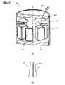
- FIG. 1 is a cutaway perspective view showing a configuration of an axial gap type rotary electric machine according to a first embodiment of the present invention.
- BRIEF DESCRIPTION OF THE DRAWINGS The fracture perspective view which shows the structure of the axial gap type rotary electric machine which concerns on the 1st Embodiment of this invention (figure which abbreviate
- FIG. 7 is a partial enlarged perspective view showing a stator core, a conductive ring and a conductive bar.
- the perspective view which shows the structure of a stator core.
- the perspective view which shows the electrical connection part of a conductive ring and a stator core.
- FIG. 15 The figure which illustrates the process of rotating the bending tool inserted in the slit and bending the bending piece.
- (A) is the elements on larger scale of FIG. 15
- (b) is a figure for demonstrating the deformation part of the circumferential direction end surface of a stator core.
- the cross-sectional schematic diagram which shows the state which formed resin filling space with the lower mold
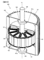
- FIG. 7 is a cutaway perspective view showing a configuration of an axial gap type rotating electric machine according to a second embodiment of the present invention.
- FIG. 10 is a cutaway perspective view showing a configuration of an axial gap type rotary electric machine according to a third embodiment of the present invention.
- FIG. 23 is a schematic cross-sectional view cut along a plane parallel to the axial direction including a center line m that divides the width of the core in the circumferential direction shown in FIG.
- the partial cross section perspective view which shows the holding member holding a core in the case of a molding process.
- the cross-sectional schematic diagram which shows the state which formed resin filling space with the lower mold
- (A) is a broken perspective view which shows the structure of the axial gap type rotary electric machine which concerns on the modification of the 3rd Embodiment of this invention,
- (b) is a metal mold
- the cross-sectional schematic diagram which shows the state which formed resin filling space with the lower mold
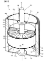
- FIGS. 1 and 2 are cutaway perspective views showing the configuration of an axial gap type rotating electrical machine according to a first embodiment of the present invention
- FIG. 2 is a view in which the mold body 140 and the rotor 150 are omitted.
- the housing 180 and the rotor 150 are shown cut along a plane that includes the central axis CL of the rotating shaft 188 and is parallel to the axial direction of the rotating shaft 188 (hereinafter also simply referred to as the axial direction).
- the axial direction hereinafter also simply referred to as the axial direction.
- each coil 122 which the conducting wire with an insulation film is wound in multiple times by the stator core 121, it has shown typically in each figure.
- An axial gap type rotating electric machine (hereinafter simply referred to as rotating electric machine 100) comprises a rotating shaft 188, a pair of rotors 150 fixed to the rotating shaft 188, and a stator 120 disposed between the pair of rotors 150. And a housing 180 for housing the pair of rotors 150 and the stator 120.
- the rotary electric machine 100 according to the present embodiment is a two-rotor one stator-type axial gap type rotary electric machine having a structure in which a stator 120 is sandwiched between a pair of rotors 150 with a predetermined gap interposed therebetween. Compared to stator type axial gap type rotating electrical machines, more magnet flux can be used, which is advantageous in terms of high efficiency and high power density.
- the pair of rotors 150 are disposed to face each other at a predetermined interval in the axial direction.
- the pair of rotors 150 have the same shape, and therefore, one of the rotors 150 will be described as a representative.
- the rotor 150 is provided at its center with an axial hole through which the rotation shaft 188 is inserted.
- the rotor 150 is integrated with the rotating shaft 188 by inserting and fixing the rotating shaft 188 in the shaft hole.
- the rotor 150 includes a substantially disk-shaped structural member 151 and a plurality of magnets 152.
- a recess 151a in which the magnet 152 is fitted is provided along the circumferential direction of the rotation shaft 188 (hereinafter, also simply referred to as the circumferential direction).
- Magnets 152 are arranged at equal intervals along the circumferential direction in the recess 151a.
- the magnet 152 is magnetized in the axial direction, and one side in the axial direction is an S pole and the other side is an N pole.
- the magnets 152 are arranged such that the magnetic poles adjacent in the circumferential direction alternately turn in opposite directions, that is, N, S, N, S,.
- One magnet 152 of the pair of rotors 150 and the other magnet 152 of the pair of rotors 150 are arranged at the same position in the circumferential direction and in the same shape when viewed from the axial direction It is done.
- a neodymium-based or samarium-based sintered magnet or ferrite magnet, a neodymium-based bonded magnet, or the like can be employed as the magnet 152.
- the stator 120 is disposed to face the rotor 150 along the axial direction.
- the stator 120 includes a plurality of stator cores (hereinafter, also simply referred to as cores 121) arranged at equal intervals along the circumferential direction, and a bobbin 110 around each core 121.
- stator cores hereinafter simply referred to as coils 122
- conductive bars 161 and 162 mounted on the bobbins 110 of each core 121, and axial both ends of the stator 120
- a pair of conductive rings 130 are formed, and as shown in FIG. 1, they are integrally molded of insulating resin in the housing 180.
- the slots of the stator 120 are open slots.
- each of the cores 121 constituting the stator 120 is held by a molded resin of insulating resin (hereinafter referred to as a molded body 140), and the molded body 140 is formed of the center bracket 182 of the housing 180. It is fixed to the inner wall.
- a molded resin of insulating resin hereinafter referred to as a molded body 140
- the housing 180 is made of conductive metal.
- the housing 180 is configured to include a cylindrical center bracket 182 provided with a radiation fin, and a pair of end brackets 181 for closing the openings at both ends of the center bracket 182.
- a space surrounded by the center bracket 182 and the pair of end brackets 181 is a housing space for housing the pair of rotors 150 and the stator 120.
- Each end bracket 181 is provided with a through hole through which the rotating shaft 188 passes, and a bearing holding portion 181 a for holding the bearing 186.
- the rotating shaft 188 is rotatably held by a bearing 186.
- FIG. 3 is a partially enlarged perspective view showing the core 121, the conductive ring 130 and the conductive bars 161 and 162. As shown in FIG. In FIG. 3, a schematic cross-sectional view taken along the line AA is shown.
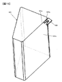
- FIG. 4 is a perspective view showing the configuration of the core 121
- FIG. 5 is a perspective view showing the configuration of the bobbin 110.
- the core 121 is formed by laminating a plurality of magnetic thin plates 121 a made of an iron-based amorphous metal, and has a substantially trapezoidal columnar shape. Note that an insulating layer having an insulating property may be provided between the magnetic thin plates 121a.
- the thickness of the magnetic thin plate 121a is exaggerated.
- the actual thickness of the magnetic thin plate 121a is, for example, about 0.2 to 0.3 mm, and the core 121 is formed by laminating about 300 to 500 magnetic thin plates 121a.
- the outer surface of the core 121 is defined and described as follows.
- a surface parallel to the axial direction close to the rotation axis 188 that is, a surface facing the rotation axis 188 is an inner surface 121i.
- An axially parallel surface close to the center bracket 182 of the housing 180 that is, a surface opposite to the center bracket 182 is an outer side surface 121o.
- two surfaces parallel to the axial direction connecting the inner surface 121i and the outer surface 121o, that is, both end surfaces in the circumferential direction facing the adjacent core 121 are side surfaces 121s.
- Both axial end surfaces of the core 121 facing the rotor 150 are top surfaces 121t.
- the lamination direction of the plurality of magnetic thin plates 121a constituting the core 121 is the radial direction of the rotary shaft 188 (hereinafter simply referred to as the radial direction Note also).
- the plane of the magnetic thin plate 121 a is orthogonal to the radial direction of the rotating shaft 188.
- the core 121 is held by the bobbin 110.
- the bobbin 110 is formed of an insulating resin material.
- the bobbin 110 has a substantially trapezoidal cylindrical cylindrical portion 111 and a pair of flange portions 112 projecting outward from the cylindrical portion 111 at both axial ends of the cylindrical portion 111. .
- a conductor wire with an insulating coating is wound a predetermined number of times around the outer peripheral surface of the cylindrical portion 111, and a coil 122 is formed (see FIG. 3).
- the cylindrical portion 111 is provided with an opening for housing the core 121, and a flange portion 112 is provided so as to surround the opening.
- the flange portion 112 is provided with an inner edge 116 along the edge of the opening.
- the inner edge portion 116 has a substantially isosceles trapezoidal shape when viewed in the axial direction, and the outer edge portion 117 is along the outer edge of the flange portion 112 opposite to the long side portion 116 a corresponding to the trapezoidal leg. Is provided.
- the long side 116a of the inner edge 116 and the outer edge 117 opposed to the long side 116a are spaced apart by a predetermined distance so as to be parallel to each other.
- the inner edge 116 and the outer edge 117 are provided so as to axially project from the flat surface of the flange 112, and the flat edge of the flange 112, the inner edge 116 and the outer edge 117 have a predetermined width.
- a groove 118 is formed.
- Each flange portion 112 is provided with a pair of groove portions 118.
- the conductive bar 161 is housed in one of the pair of groove portions 118, and the conductive bar 162 is housed in the other.
- the cross-sectional shape of each of the conductive bars 161 and 162 is rectangular.
- the width of each conductive bar 161, 162 is formed to be the same as or slightly larger than the width of the groove 118 to be stored, and each conductive bar 161, 162 is fitted and fixed to the groove 118.
- Each conductive bar 161, 162 is formed longer than the long side 116a of the inner edge portion 116, and one end of each conductive bar 161, 162 is located radially inward of one end of the long side 116a, The other end of each conductive bar 161, 162 is located radially outward of the other end of the long side portion 116a. Since each conductive bar 161, 162 is disposed between the coil 122 and the rotor 150, electrostatic coupling between the coil 122 and the rotor 150 is shielded.
- the radially outer end portions 161e and 162e of the conductive bars 161 and 162 are held by the inner circumferential portion 132 of the conductive ring 130 and the flange portion 112 of the bobbin 110, which will be described later. And are electrically and mechanically connected.
- a step is formed on the surface of the inner peripheral portion 132 of the conductive ring 130 on the side of the flange portion 112 as shown in the schematic sectional view taken along line AA in FIG. 3, and the diameter of the inner peripheral portion 132 is
- the direction inner side portion is a thin portion formed thinner than the thickness of the radially outer side portion of the inner circumferential portion 132.
- the end portions 161 e and 162 e of the conductive bars 161 and 162 are in contact with the thin-walled portion of the inner portion of the inner circumferential portion 132.
- the axial length of the core 121 is longer than the axial length of the bobbin 110, and both axial end portions of the core 121 protrude from the both end openings of the cylindrical portion 111 by a predetermined length.
- both end portions of the core 121 protruding from the bobbin 110 will be referred to as protruding end portions 121 e. Therefore, the inner surface 121i, the outer surface 121o and the pair of side surfaces 121s excluding the projecting end 121e of the core 121 are covered by the cylindrical portion 111, and the inner surface 121i, the outer surface 121o and the pair of side surfaces 121s in the projecting end 121e and The top surface 121t is exposed.
- two pins 115 and a lead-out portion 119 are provided on the side of the center bracket 182 in the flange portion 112 of the bobbin 110.
- the two pins 115 are erected on the flange portion 112 so as to be parallel to the axial direction in each of the pair of flange portions 112.
- the lead-out portion 119 is a portion through which the lead-out wire of the coil 122 is inserted, and is formed only in one of the pair of flange portions 112.
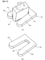
- FIG. 6 is a perspective view showing the configuration of the conductive ring 130.
- the conductive ring 130 is a conductive member that electrically connects the cores 121 and the center bracket 182.
- the conductive ring 130 has an annular base 133 in contact with the inner surface of the center bracket 182 and a plurality of protrusions 136 projecting from the annular base 133 toward the center of the rotation shaft 188. It is integrally molded.
- Each of the plurality of protrusions 136 is in contact with the side surface 121s of each of the plurality of cores 121, as shown in FIG.
- the protrusion 136 may be in contact with both of the pair of side surfaces 121s.
- the base portion 133 of the conductive ring 130 is an annular portion on the outer circumferential side (hereinafter referred to as the outer circumferential portion 131) and an annular portion on the inner circumferential side (hereinafter referred to as the inner circumferential portion 132)
- the thickness is different, and a step is formed on the surface opposite to the flange portion 112 side.
- the thickness of the outer peripheral part 131 is about 3 mm, and the thickness of the inner peripheral part 132 is about 1 mm.
- a step is formed on the surface of the inner circumferential portion 132 on the side of the flange portion 112, and the end portions 161e and 162e of the conductive bars 161 and 162 are in contact with the inner portion of the inner circumferential portion 132. It is considered as a thin portion.
- the base 133 is provided with a fitting hole 135 into which the pins 115 provided on the bobbin 110 described above are fitted.
- the base portion 133 is provided with a notch portion 138 in which the lead-out portion 119 provided on the above-described bobbin 110 is disposed.
- a plurality of slits 134 extending radially outward from the inner peripheral end surface are arranged in parallel along the circumferential direction.
- a plurality of projecting pieces 132a radially inward from the outer peripheral portion 131 are provided along the circumferential direction.
- the shape of the plurality of slits 134 is set in consideration of the positional relationship with the fitting holes 135 so that the fitting holes 135 and the slits 134 are not connected.
- the projecting portion 136 is provided so as to protrude radially inward from the base portion 133 along the radial direction.
- the protrusion 136 is provided with a slit 139 extending radially outward from the tip of the protrusion 136.
- the projecting portion 136 is divided into the pair of projecting pieces 137 by the slit 139 and has a bifurcated shape.
- FIG. 7 is a perspective view showing the electrical connection portion between the conductive ring 130 and the core 121. As shown in FIG. As shown in FIG. 7, of the pair of projecting pieces 137, the projecting piece 137 closer to the core 121 is in contact with the side surface 121 s of the core 121.
- FIG. 8 is a flow chart for explaining a process of manufacturing the rotary electric machine 100
- FIG. 9 is a flow chart for explaining an arrangement process.
- the method of manufacturing the rotating electrical machine 100 includes a preparation step S100, a conductive ring formation step S110, a core formation step S120, a bobbin attachment step S130, a coil winding step S140, and a placement step S150.
- bending step S160, molding step S170, rotor assembling step S180, connection step S190, and closing step S195 are examples of manufacturing the rotating electrical machine 100.
- each component which comprises the rotary electric machine 100 for example, the center bracket 182, the end bracket 181, the magnetic thin plate 121a which comprises the core 121, the rotor 150 grade
- a rotating shaft 188 is attached to one of the pair of rotors 150 in advance.
- the conductive ring formation step S110 the conductive ring 130 is formed by pressing a metallic plate member having conductivity.
- -Core formation process In the core forming step S120, a predetermined number of rectangular elongated amorphous foil strips made of iron-based amorphous metal are stacked, pressed from both sides in the stacking direction, and then cut into substantially trapezoidal columns, The core 121 is formed.
- the core 121 formed in the core forming step S120 is press-fit into the opening of the cylindrical portion 111 of the bobbin 110. Both ends of the core 121 project from both ends of the cylindrical portion 111 of the bobbin 110.
- the respective top surfaces 121t constituting the end surfaces of the core 121 are set at positions separated from the flange portion 112 of the bobbin 110 by a predetermined distance.
- the conductive bars 161 and 162 are fitted in the grooves 118 of the flange 112.
- the wire with the insulating coating is wound around the cylindrical portion 111 of the bobbin 110 a predetermined number of times to form the coil 122. That is, the coil 122 is attached to the core 121 via the bobbin 110.
- the lead wire of the coil 122 is disposed at the opening of the lead portion 119 provided on the flange portion 112 of the bobbin 110.
- the core 121, the conductive ring 130, and the center bracket 182 are placed at predetermined positions.
- FIG. 10 is a schematic cross-sectional view for explaining the process of arranging the lower conductive ring 130L and the core 121
- FIG. 11 is a schematic cross-sectional view for explaining the process of arranging the center bracket 182 and the upper conductive ring 130U.
- FIGS. 10 and 11 schematically show a cross section of each member cut in a plane along the axial direction and including the central axis of the rotation axis 188.
- the vertical direction is defined as illustrated.
- the lower mold 191 which is the lower mold, is used to lower the conductive ring 130L. Place.
- the lower mold 191 has a base 191a, a first cylindrical portion 191b vertically provided from the base 191a, and a second cylindrical portion 191c provided vertically from the central portion of the first cylindrical portion 191b. doing.
- Each of the first cylindrical portion 191 b and the second cylindrical portion 191 c has a circular cross section.
- the diameter of the first cylindrical portion 191 b is set to substantially the same size as the inner diameter of the center bracket 182.
- the diameter of the second cylindrical portion 191 c is set to a size slightly larger than the diameter of the rotating shaft 188.
- the upper surfaces of the first cylindrical portion 191b, the second cylindrical portion 191c, and the base 191a are flat surfaces, and the lower conductive ring 130L is disposed on the upper surface of the first cylindrical portion 191b.
- the core arranging step S153 twelve cores 121 are arranged on the upper surface of the first cylindrical portion 191b so that the lead lines (not shown) are arranged on the upper side.
- the lower top surface 121t of the core 121 is in contact with the upper surface of the first cylindrical portion 191b, and the flange portion 112 of the bobbin 110 is in contact with the lower conductive ring 130L.
- end portions 161e and 162e of the conductive bars 161 and 162 are disposed between the flange portion 112 of the bobbin 110 and the inner circumferential portion 132 of the lower conductive ring 130L.
- the plurality of cores 121 are arranged at equal intervals along the circumferential direction such that the lamination direction of the plurality of magnetic thin plates 121 a constituting the core 121 is the radial direction.
- the core 121 can be easily positioned by fitting the pins 115 of the bobbins 110 attached to the cores 121 into the fitting holes 135 of the lower conductive ring 130L.
- the lower conductive ring 130 ⁇ / b> L is disposed radially outward of the projecting end 121 e of the core 121.
- the opening at the lower end of the center bracket 182 is fitted to the first cylindrical portion 191b, and one end surface of the center bracket 182 is the upper surface of the base 191a. Abut on.
- the center bracket 182 is provided with a plate-like upper support protrusion 183U and a lower support protrusion 183L protruding from the inner surface.
- the upper support protrusion 183U and the lower support protrusion 183L have an annular shape when viewed from the axial direction.
- the upper support protrusion 183U and the lower support protrusion 183L are disposed at predetermined intervals corresponding to the axial dimension of the bobbin 110.
- the lower support protrusion 183 ⁇ / b> L of the center bracket 182 is in contact with the lower conductive ring 130 ⁇ / b> L at the radially outer side of the flange portion 112 of the bobbin 110.
- step S157 (see FIG. 9) of arranging the other of the pair of conductive rings 130 (hereinafter referred to as the upper conductive ring 130U), the upper conductive ring 130U is disposed radially outward of the projecting end 121e of the core 121. Do.
- the upper conductive ring 130U is press-fit from the opening on the upper end side of the center bracket 182, and the base portion 133 of the upper conductive ring 130U is mounted on the flange portion 112 and the upper support protrusion 183U provided on the upper end of the bobbin 110 attached to the core 121 Do.
- end portions 161e and 162e of the conductive bars 161 and 162 are disposed between the flange portion 112 of the bobbin 110 and the inner peripheral portion 132 of the upper conductive ring 130U.
- the upper conductive ring 130U can be easily positioned relative to the core 121 by fitting the pin 115 of the bobbin 110 into the fitting hole 135 of the upper conductive ring 130U. Further, by bringing the upper support projection 183U of the center bracket 182 and the upper conductive ring 130U into contact with each other, axial positioning of the upper conductive ring 130U with respect to the center bracket 182 is performed.
- the base 133 of the upper conductive ring 130U is in contact with the inner surface of the center bracket 182. Specifically, the outer peripheral side surface of the annular base portion 133 is in contact with the inner peripheral surface of the center bracket 182, and the lower surface of the base portion 133 is in contact with the upper surface of the upper support protrusion 183U.
- FIG. 12 is a view showing a state before the protrusion 136 of the conductive ring 130 is bent.
- FIG. 11 when the upper conductive ring 130U is positioned, as shown in FIG. 12, the circumferential side of the projecting end 121e of the core 121 projected from the upper end of the bobbin 110, ie, adjacent cores
- the protrusions 136 are disposed between the two members 121.
- the protruding piece closer to the core 121 (hereinafter referred to as a bending piece 137a) of the pair of protruding pieces 137 is bent toward the core 121, and the bending piece 137a is cored.
- the side surface 121s of 121 is brought into contact.
- FIG. 13 is a view for explaining the process of inserting the bending tool 196 into the slit 139 of the projection 136 of the conductive ring 130
- FIG. 14 is a bending piece 137a by rotating the bending tool 196 inserted into the slit 139. It is a figure explaining the process of making it bend.
- the protrusion 136 is shown enlarged.
- a flat bending tool 196 for example, a tip of a flathead screwdriver, is inserted into the slit 139 of the projection 136.
- one end of the bending tool 196 is brought into contact with the projecting piece far from the core 121 of the pair of projecting pieces 137 (hereinafter referred to as the holding piece 137b) while bending
- the bending tool 196 is rotated so that the other end of the tool 196 approaches the core 121.
- one end of the bending tool 196 is in contact at a point P1 on the base end side of the holding piece 137b.
- the other end of the bending tool 196 is in contact at a point P2 on the tip side of the bending piece 137a.
- the same level of force from the bending tool 196 acts on each of the position P1 of the holding piece 137b and the position P2 of the bending piece 137a.
- the bending piece 137a can be bent toward the side surface 121s of the core 121 without deforming the holding piece 137b.
- the holding piece 137b has substantially the same projection length as the bending piece 137a, but the holding piece 137b has a length for bending at point P1 when bending the bending piece 137a. It may be long enough to support one end of the tool 196.
- FIG. 14B when the bending piece 137a is bent by a predetermined angle, as shown in FIG. 15, a part of the bending piece 137a pushes the side surface 121s of the core 121.
- FIG. 15 is a view for explaining a state in which the bending piece 137 a is pushed into the side surface 121 s of the core 121.
- Fig.16 (a) is the elements on larger scale of FIG.
- FIG.16 (b) is a figure for demonstrating the deformation part of 121 s of side surfaces of the core 121.
- FIGS. 15 and 16A when the bending piece 137a is bent, the side portion of the bending piece 137a bites into the core 121.
- the side surface 121s of the core 121 is recessed to form a recess 121c.
- the contact area between the bent piece 137a and the core 121 corresponds to the area of the entire inner surface of the recess 121c. Therefore, the contact area can be increased as compared with the case where the bending piece 137a is abutted on the side surface 121s without biting into the core 121.
- FIG. 17 is a schematic cross-sectional view showing a state in which a resin-filled space is formed by the lower die 191 and the upper die 193
- FIG. 18 is a schematic cross-sectional view showing a state in which a plurality of cores 121 are integrally molded.
- FIG. 17 and FIG. 18 schematically show a cross-sectional portion obtained by cutting each member in a plane along the axial direction and including the central axis of the rotation axis 188.
- the vertical direction is defined as illustrated.
- the diameter of the first cylindrical portion 193 b is the same as the diameter of the first cylindrical portion 191 b of the lower die 191. That is, the diameter of the first cylindrical portion 193 b of the upper die 193 is set to substantially the same size as the inner diameter of the center bracket 182.
- the diameter of the second cylindrical portion 193 c has the same diameter as that of the second cylindrical portion 191 c of the lower die 191.
- the diameter of the second cylindrical portion 193 c of the upper die 193 is set to a size slightly larger than the diameter of the rotating shaft 188.
- the lower surfaces of the first cylindrical portion 193b, the second cylindrical portion 193c, and the base 193a are flat.
- the outer peripheral portion 131 of the base portion 133 of the upper conductive ring 130U and the top surface 121t of the core 121 are in contact with the lower surface of the first cylindrical portion 193b.
- the upper end surface of the center bracket 182 is in contact with the lower surface of the base 193a.
- the lower surface of the second cylindrical portion 193 c is disposed to face the upper surface of the second cylindrical portion 191 c of the lower mold 191.
- a predetermined gap is formed between the second cylindrical portion 193c of the upper mold 193 and the second cylindrical portion 191c of the lower mold 191, thereby forming a flow path through which the resin flows.
- a resin having fluidity and insulation is injected from the injection hole 193 h provided in the upper mold 193 into the space S for resin filling surrounded by the lower mold 191, the upper mold 193 and the center bracket 182, and the space S is Fill the resin. Thereafter, when the resin is cured, a mold body 140 shown in FIGS. 18 and 1 is formed.
- FIG. 19 is a view showing the relationship between the core 121 and the mold body 140.
- FIG. 19A is a view showing a state before molding, which corresponds to a schematic cross-sectional view cut along a plane parallel to the axial direction along the line XIX-XIX in FIG.
- FIG. 19B is a view showing a state after molding, which corresponds to a schematic cross-sectional view cut along a plane parallel to the axial direction along line XIX-XIX in FIG.
- the projecting end 121e of the core 121 is exposed before molding.
- the mold body 140 covers the outer surface of the projecting end 121e excluding the top surface 121t.
- the pair of side surfaces 121s, the inner side surface 121i and the outer side surface 121o in each of the protruding end portions 121e are covered by the mold body 140, and the top surface 121t is exposed.
- the rotary shaft 188 on which one of the rotors 150 is mounted is mounted on the bearing 186 of one of the end brackets 181.
- One rotor 150 is disposed opposite to one end face in the axial direction of the stator 120, and one end bracket 181 closes the opening at one end side of the center bracket 182 to fix the end bracket 181 to the center bracket 182 .
- the other rotor 150 is mounted on the rotating shaft 188 so as to sandwich the stator 120 with one of the mounted rotors 150.
- connection step S190 the lead wire of each core 121 is connected to a connection conductive member (not shown).
- the coils 122 attached to each of the plurality of cores 121 can be connected by star connection.
- Annular conductive members for connection corresponding to U phase, V phase and W phase hereinafter referred to as U phase connection ring, V phase connection ring and W phase connection ring, respectively
- a neutral point A ring-shaped conductive member for wire connection (hereinafter referred to as a wire connection ring for neutral point) to be configured is a predetermined member between the rotor 150 and the end bracket 181 by a support member or the like (not shown) having an insulating property. Place in position.
- each of the plurality of coils 122 constituting the U-phase winding is connected to the U-phase connection ring, and the other end is connected to the neutral point connection ring.
- One end of each of the plurality of coils 122 constituting the V-phase winding is connected to the V-phase connection ring, and the other end is connected to the neutral point connection ring.
- One end of each of the plurality of coils 122 constituting the W-phase winding is connected to the W-phase connection ring, and the other end is connected to the neutral point connection ring.
- the installation position of each connection ring is not limited between the rotor 150 and the end bracket 181.
- the neutral point connection ring may be disposed on the flange portion 112 of the bobbin 110. In this case, the step of connecting the neutral point connection ring and the lead wire of the coil 122 is performed in the arrangement step S150 or the like.
- the stator 120 of the rotary electric machine 100 formed in this manner includes a plurality of cores 121 arranged in the circumferential direction of the rotation shaft 188, a bobbin 110 for holding the core 121, and a coil 122 wound around the bobbin 110. , Conductive bars 161 and 162 for shielding electrostatic coupling between the coil 122 and the rotor 150, and a conductive ring 130 for electrically connecting the side surface 121s, which is the circumferential end surface of each core 121, and the housing 180. have.
- the core 121 and the housing 180 are electrically connected by the conductive ring 130. Therefore, the core 121 is grounded to the housing 180, and the core 121 can be prevented from becoming a floating potential.
- the stator 120, the housing 180, and the rotation shaft 188 of the rotor 150 held in the housing 180 via the bearing 186 provided in the housing 180 can be at the same potential, and the occurrence of electrolytic corrosion of the bearing 186 Can be prevented.
- the conductive bars 161 and 162 are accommodated in the groove portion 118, even if a molding pressure is applied to the conductive bars 161 and 162 in the molding process, displacement of the positions of the conductive bars 161 and 162 is prevented. As a result, the conductive bars 161 and 162 can be fixed at predetermined positions, and the shield by the conductive bars 161 and 162 can be reliably performed.
- the conductive bars 161 and 162 are held by the flange portion 112 of the bobbin 110 and the conductive ring 130. Thereby, positional deviation of the conductive bars 161 and 162 can be prevented more reliably. Further, since the conductive bars 161 and 162 and the housing 180 are electrically connected via the conductive ring 130, the conductive bars 161 and 162 are grounded to the housing 180, and the conductive bars 161 and 162 have a floating potential. Can be prevented.
- the core 121 is composed of a plurality of magnetic thin plates 121 a stacked in the radial direction of the rotating shaft 188.
- the conductive ring 130 electrically connects the housing 180 and the side surface 121s of the core 121, that is, the circumferential end surface of the core 121. For this reason, it is not affected by the radial dimension of the core 121 formed by laminating the magnetic thin plates 121a in the radial direction, that is, the dimensional accuracy in the stacking direction.
- the conductive member and the core 121 are electrically connected by the conductive member, and the radial dimension of the core 121 is slightly shorter than the design value, the conductive member and the core 121 There is a concern that it will not touch.
- the housing 180 and the outer surface 121o of the core 121 are electrically connected by a conductive member, and the radial dimension of the core 121 is slightly longer than the design value, depending on the distance between the core 121 and the housing 180. There is a concern that the conductive member is pinched and the conductive member is deformed.
- dimensional tolerance between the outer surface 121o of the core 121 and the inner surface of the housing 180 or the lamination direction of the core 121 The dimensional tolerances must be strictly defined.
- the magnetic thin plate 121a constituting the core 121 is made of an amorphous foil band, and the thickness (for example, about 0.3 mm) is thinner than the thickness (for example, about 0.5 mm) of the electromagnetic steel sheet.
- the number of laminated layers is also larger than that of the electromagnetic steel sheet.
- the housing 180 and the core 121 can be reliably and electrically connected without an excessive force acting on the conductive ring 130.
- the dimensional tolerance is relaxed, which facilitates manufacture.
- the projecting portion 136 is provided with a slit 139 directed radially outward of the rotation shaft 188 from the tip of the projecting portion 136. Therefore, by inserting the bending tool 196 into the slit 139 and rotating it, the bent piece 137a of the projection 136 can be easily bent, and the working efficiency can be improved.
- the flange portion 112 of the bobbin 110 is provided with a pair of pins 115 for positioning, and the conductive ring 130 is provided with a pair of fitting holes 135 into which the pins 115 are inserted.
- the conductive ring 130 can be easily positioned by fitting the pin 115 and the fitting hole 135. The improvement of the workability can reduce the number of manufacturing processes.
- the magnetic thin plate 121a constituting the core 121 is made of amorphous metal. Thereby, energy loss (hysteresis loss) can be reduced compared with the core 121 which laminates
- the thickness (for example, about 0.3 mm) of the magnetic thin plate 121a constituting the core 121 is thinner than the thickness (for example, about 0.5 mm) of the electromagnetic steel sheet. For this reason, compared with the core which consists of an electromagnetic steel plate, the core 121 of this Embodiment is easy to deform
- the bending piece 137a can be bited into the side surface 121s of the core 121.
- the connection strength is improved, and the contact area between the bent piece 137a and the core 121 can be increased, so that the electrical resistance is reduced.
- the thickness of the base portion 133 is changed or a plurality of slits 134 are formed to reduce the eddy current loss and improve the motor efficiency. I am trying to
- the influence of the eddy current is large.
- the thickness of the inner peripheral portion 132 is reduced (for example, about 1 mm) with respect to the thickness (for example, about 3 mm) of the outer peripheral portion 131 of the conductive ring 130, the eddy current loss in the inner peripheral portion 132 Can be reduced.
- the inner circumferential portion 132 of the base portion 133 is provided with a plurality of slits 134 radially outward from the inner circumferential end surface.
- the slit 134 cuts off the path of the eddy current, so that the eddy current loss can be reduced as compared with the case where the slit 134 is not provided.
- the projecting portion 136 is provided with a slit 139. Since the path of the eddy current is blocked by the slit 139, the eddy current loss can be reduced as compared with the case without the slit 139.
- the thickness of the outer peripheral portion 131 is made thicker (for example, about 3 mm) than the thickness (for example, about 1 mm) of the inner peripheral portion 132 of the conductive ring 130.
- the rigidity is improved while suppressing an increase in the eddy current loss.
- the conductive ring 130 is press-fit to the center bracket 182, so that it is possible to prevent the conductive ring 130 from being deformed by the clamping force from the center bracket 182 acting on the conductive ring 130.
- the thickness of the bending piece 137a is the same as that of the inner circumferential portion 132, so that the bending piece 137a can be easily bent and deformed, and the workability is good.
- the plurality of cores 121 are integrally molded of insulating resin so that the side surface 121 s, which is the circumferential end surface of the core 121, is covered with the projecting portion 136 of the conductive ring 130.
- the mold body 140 can hold the core 121, and can further maintain the connection strength at the electrical connection portion between the core 121 and the conductive ring 130. As a result, the rotary electric machine 100 excellent in vibration resistance and impact resistance can be provided.
- an annular base portion 133 in contact with the inner surface of the housing 180 and a plurality of projecting portions 136 projecting from the base portion 133 toward the center of the rotation shaft 188 are integrally formed. Therefore, in the arranging step S150, relative positioning of the cores 121 can be facilitated while preventing the cores 121 from being displaced in the axial direction or tilting. That is, the arrangement workability of the conductive ring 130 and the core 121 can be improved as compared with the case where the plurality of conductive members are arranged.
- FIG. 20 is a cutaway perspective view showing the configuration of an axial gap type rotary electric machine according to a second embodiment
- FIG. 21 is a view of one of the core 121 and the conductive member 230 of FIG.
- the illustration of the mold body 140 is omitted.
- the rotating electrical machine 200 of the second embodiment is configured the same as the rotating electrical machine 100 described in the first embodiment except for the configuration of the conductive member 230.
- the conductive ring 130 which is the conductive member of the first embodiment, an annular base portion 133 and a plurality of projecting portions 136 projecting from the base portion 133 are integrally formed (see FIG. 6).
- the conductive member 230 of the second embodiment corresponds to the one obtained by dividing the annular base portion 133 described in the first embodiment, and as shown in FIG.
- the conductive members 230 are individually attached to the above.
- the conductive member 230 is integrally provided with an arc-shaped base portion 233 in contact with the inner surface of the center bracket 182 and a single protrusion 136 projecting from the base portion 233.
- the conductive member 230 can be easily positioned by fitting the pair of fitting holes 135 provided in the conductive member 230 with the pair of pins 115 provided upright on the flange portion 112 of the bobbin 110.
- the base portion 233 of the conductive member 230 is in contact with the inner surface of the center bracket 182, and the bending piece 137a of the projection 136 is bent by the bending tool 196 (see FIGS. 13 and 14) to contact the side surface 121s of the core 121. There is.
- the plurality of conductive members 230 are formed by dividing the substantially annular conductive ring 130 in the circumferential direction.
- the loss due to the eddy current is further reduced compared to the substantially annular conductive ring 130 described in the first embodiment. It can be reduced.
- the number of divisions is not limited to the number of cores 121.
- FIGS. 22 to 25 An axial gap type rotary electric machine according to a third embodiment will be described with reference to FIGS. 22 to 25.
- FIG. In the figure, the same or corresponding parts as in the first embodiment are designated by the same reference numerals, and the description will be omitted. Hereinafter, the difference from the first embodiment will be described in detail.
- FIG. 22 is a cutaway perspective view showing a configuration of an axial gap type rotating electric machine (hereinafter simply referred to as rotating electric machine 300) according to the third embodiment
- FIG. 23 is a width in the circumferential direction of core 121 shown in FIG. Fig. 3 is a schematic cross-sectional view cut along a plane parallel to the axial direction, including a center line m that divides 2 into two.
- the conductive ring and the conductive bar are not shown.
- illustration of the rotating shaft is omitted, and the central axis CL of the rotating shaft is illustrated.
- the top surface 121t of the core 121 is exposed without being covered by the mold body 140 .
- the magnetic characteristics are inferior as compared to the case where a rare earth magnet is used, so it is necessary to increase the diameter of the rotor 150 is there.
- the size and weight of the stator core 121 increase, so it is necessary to further increase the holding strength of the core 121. Therefore, in the third embodiment, the top surface 121t of the core 121 is covered with the mold body 340 to increase the retention strength of the core 121.
- a technique for enhancing the holding strength for example, there is a technique (hereinafter referred to as a prior art) described in JP-A-2007-28855.
- the core while inserting a T-shaped core into a stator yoke core, the core is made to project from the stator yoke core, and the entire protrusion is covered with resin.
- a convex portion extending in the radial direction is formed on the facing surface of the core facing the rotor, and the core is covered with resin except for the convex portion to enhance the holding strength.
- providing a convex portion on the core is not preferable because it leads to an increase in the number of manufacturing steps.
- the core is formed by laminating magnetic thin plates made of an amorphous foil band, there is also a problem that the formation of the convex portion is difficult.
- rotating electrical machine 300 differs from the rotating electrical machine according to the first embodiment in the number of cores 121 and the shape and size of each component but has the same configuration. That is, rotating electric machine 300 includes a rotating shaft (not shown), a pair of rotors 150 fixed to the rotating shaft, a stator 120 disposed between a pair of rotors 150, a pair of rotors 150 and a fixing And a housing for accommodating the child 120 (only the center bracket 182 is shown in FIGS. 22 and 23).
- FIG. 24 is a partial cross-sectional perspective view showing the holding member 397 for holding the core 121 in the molding step.
- the holding member 397 is made of an insulating resin, and has an annular outer peripheral portion 398 and a plurality of sandwiching portions 399 projecting from the outer peripheral portion 398 toward the center of the rotation shaft.
- the holding member 397 is attached to the center bracket 182 of the housing 180 by press-fitting or adhesion, and the outer peripheral portion 398 of the holding member 397 is fixed to the inner peripheral surface of the center bracket 182.
- a plurality of sandwiching portions 399 are provided at predetermined intervals along the circumferential direction.
- An opening 399a into which the core 121 and the bobbin (not shown) are press-fitted is provided between the pair of sandwiching portions 399 adjacent in the circumferential direction.
- the outer peripheral portion 398 of the holding member 397 is provided with a plurality of through holes extending in the axial direction, which becomes a flow path of the fluid resin during molding.
- the coil 122 is wound around the upper and lower sides of the sandwiching portion 399 so as to avoid the sandwiching portion 399.
- Each core 121 is attached to the opening 399a by press-fitting or the like, and is held by a pair of holding portions 399 adjacent in the circumferential direction.
- the holding member 397 is formed of a resin material capable of being elastically deformed and having an appropriate flexibility so that the core 121 can be press-fitted into the opening 399a, and the trapezoidal shape of the core 121 having a substantially trapezoidal column shape. The difference between the lengths of the upper and lower bases in the cross section is set small.
- the shape of the core 121 may be a substantially rectangular parallelepiped shape instead of the substantially trapezoidal prismatic shape.
- the upper surface of the first cylindrical portion 191 b of the lower mold 191 is brought into contact with the lower top surface 121 t of the core 121, and The resin was filled in a state where the lower surface of the first cylindrical portion 193 b was in contact with the top surface 121 t on the upper side of the core 121.
- FIG. 25 is a schematic cross-sectional view showing a state in which a resin-filled space is formed by the lower mold 391 and the upper mold 393.
- FIG. 25 is a plane along the axial direction and is a plane including the central axis of the rotation axis 188, and schematically shows a cross-sectional portion obtained by cutting each member.
- the vertical direction is defined as illustrated.
- the lower mold 391 includes a base 391 a, a first cylindrical portion 391 b erected vertically from the base 391 a, and a first erected vertically from a central portion of the first cylindrical portion 391 b. And 2 cylindrical portion 391c.
- Each of the first cylindrical portion 391 b and the second cylindrical portion 391 c has a circular cross section.
- the diameter of the first cylindrical portion 391 b is set to substantially the same size as the inner diameter of the center bracket 182.
- the diameter of the second cylindrical portion 391 c is set to a size slightly larger than the diameter of the rotating shaft 188.
- the top surfaces of the first cylindrical portion 191b, the second cylindrical portion 191c, and the base 191a are flat.
- the upper die 393 is vertically movable up and down, and a base 393a, a first cylindrical portion 393b vertically erected from the base 393a, and a second cylindrical portion vertically erected from the first cylindrical portion 393b And 393c.
- the diameter of the first cylindrical portion 393 b is the same as the diameter of the first cylindrical portion 391 b of the lower mold 391. That is, the diameter of the first cylindrical portion 393 b of the upper die 393 is set to substantially the same size as the inner diameter of the center bracket 182.
- the diameter of the second cylindrical portion 393c is the same as the diameter of the second cylindrical portion 391c of the lower mold 391.
- the diameter of the second cylindrical portion 393 c of the upper die 393 is set to a size slightly larger than the diameter of the rotating shaft 188.
- the lower surfaces of the first cylindrical portion 393b, the second cylindrical portion 393c, and the base 393a are flat.
- a holding member 397 is fixed in advance to the center bracket 182, and a core 121 is mounted to the holding member 397.
- the opening on the lower end side of the center bracket 182 is fitted to the first cylindrical portion 391b, and one end surface of the center bracket 182 is brought into contact with the upper surface of the base 391a.
- a gap is formed between the upper surface of the first cylindrical portion 391 b of the lower mold 391 and the top surface 121 t on the lower side of the core 121.
- the lower surface of the second cylindrical portion 393 c abuts on the upper surface of the second cylindrical portion 391 c of the lower die 391.
- a gap is formed between the lower surface of the first cylindrical portion 393 b of the upper mold 393 and the top surface 121 t on the upper side of the core 121.
- a resin having fluidity and insulating properties is injected from the injection hole 393 h provided in the upper mold 393 into the space S for resin filling surrounded by the lower mold 391, the upper mold 393, and the center bracket 182, Fill the resin. Thereafter, when the resin is cured, a mold body 340 shown in FIGS. 22 to 24 is formed. As shown in FIG. 24, the mold body 340 covers the pair of side surfaces 121s, the inner surface 121i, the outer surface 121o, and the top surface 121t of each of the protruding end portions 121e of the core 121.
- the following function and effect can be obtained.
- the entire outer surface of the projecting end 121e of the core 121 projecting from the bobbin 110, that is, the top surface 121t and the pair of side surfaces 121s, the inner surface 121i, and the outer surface 121o are covered with the mold body 340. Therefore, compared to the first embodiment, the holding strength of the core 121 can be increased, and a rotating electrical machine excellent in vibration resistance and impact resistance can be provided. Furthermore, the oxidation reaction of the core 121 by the moisture contained in the air in the housing 180 can be suppressed. That is, since the occurrence of rusting of the core 121 can be suppressed, it is possible to provide a rotating electrical machine that can maintain motor performance for a long time.
- Amorphous foil strips are thinner than magnetic steel plates etc. and are difficult to process because they are hard. Therefore, when making the core a complicated shape as in the prior art, it is amorphous on the magnetic thin plate 121a. It is difficult to adopt a foil band. On the other hand, in the present embodiment, since the top surface 121t and the side surface 121s of the core 121 can be formed in a simple trapezoidal prism shape, the core 121 can be easily manufactured.
- a ferrite magnet can be adopted as the magnet 152 mounted on the rotor 150. Ferrite magnets can be obtained inexpensively and stably as compared to other magnet materials, so the cost of the rotary electric machine 100 can be reduced.
- FIG. 26A is a view similar to FIG. 22 and is a cutaway perspective view showing a configuration of an axial gap type rotating electrical machine according to a modification of the third embodiment.
- the mold body 440 is provided with a recess 441 that is recessed toward the top surface 121t of the core 121.
- FIG. 26 (b) is a view showing a die contact area 421 d at the axial end face of the core 121, that is, the top face 121 t.
- FIG. 26B On each top surface 121t of the core 121, a rectangular area extending in the radial direction is set as a mold contact area 421d.
- FIG. 27 is a view similar to FIG. 25 and is a schematic cross-sectional view showing a state in which the resin filling space is formed by the lower mold 491 and the upper mold 493.
- the lower mold 491 has a configuration similar to that of the lower mold 491 described in the third embodiment, except that a rectangular parallelepiped contact convex portion 494 is provided from the upper surface of the first cylindrical portion 391b. Is different from the lower mold 391.
- the upper mold 493 has the same configuration as the upper mold 393 described in the third embodiment, but a rectangular parallelepiped contact convex portion 494 is provided from the lower surface of the first cylindrical portion 393b. The point is different from the upper mold 393.
- the contact convex portion 494 is provided for each core 121.
- the mold contact area 421d in which the contact convex part 494 of the mold is in contact is set on each of the pair of top surfaces 121t.
- the mold contact areas 421d of the pair of top surfaces 121t are set at the same position and in the same shape when viewed from the axial direction.
- Each of the die contact areas 421d of the pair of top surfaces 121t is set at least on the same vertical line. For this reason, in the molding process, the contact convex portion 494 of the upper die 493 and the contact convex portion 494 of the lower die 491 are disposed to face each other on the same vertical line.
- the core 121 is sandwiched between the contact convex portion 494 of the upper mold 493 and the contact convex portion 494 of the lower mold 491 on the same vertical line, so the core 121 is inclined or misaligned. Can be prevented. Since each core 121 can be held by the mold body 440 at an appropriate position, a rotary electric machine with excellent motor efficiency can be provided.
- the holding member 397 described in the third embodiment can be omitted.
- the projecting piece 132a (see FIGS. 3 and 21) provided on the base portion 133 facing the outer side surface 121o of the core 121 may be in contact with the outer side surface 121o.
- the heat of the core 121 can be absorbed from the outer side surface 121o and transmitted to the housing 180, so that the core 121 can be cooled more effectively.
- a member having thermal conductivity is attached to the gap to form the outer surface 121o and the projecting piece 132a. It may be thermally connected via a heat conductive member.
- the present invention is not limited to this.
- the protruding portion 136 without the slit 139 may be pressed against the side surface 121 s of the core 121 to electrically connect the core 121 and the protruding portion 136.
- the present invention is not limited to the case where the core 121 and the protrusion 136 are brought into contact by bending the protrusion 136 toward the side surface 121s of the core 121.
- a protruding portion 136 slightly inclined toward the core 121 is formed.
- the protrusion 136 may be elastically deformed in a direction away from the core 121 in advance, and then the protrusion 136 may be brought into contact with the core 121 by an elastic restoring force.
- the shapes of the conductive ring 130 and the conductive member 230 are not limited to the embodiments described above. It is sufficient that the side surface 121s of the core 121 and the housing 180 can be electrically connected, and various shapes can be adopted. Further, the shapes of the conductive bars 161 and 162 and the shapes of the groove portions 118 in which the conductive bars 161 and 162 are accommodated are not limited to the above-described embodiment. In the embodiment described above, the conductive bars 161 and 162 have been described to have an example in which the cross-sectional shape is a rectangular shape, but for example, the cross-sectional shape may be various shapes such as a circular shape, a semicircular shape, an elliptical shape, and a polygonal shape. be able to.
- the type of motor is not limited to the above embodiment.
- a switched reluctance motor (SR motor) having a rotor having salient poles may be employed.
- an axial gap type rotating electrical machine of two rotors and one stator type has been described as an example, but the present invention is not limited to this.
- the present invention can also be applied to an axial gap type rotary electric machine of a 1 rotor 1 stator type.
- the core 121 may be formed by laminating electromagnetic steel sheets.
- the core 121 may be formed of a soft magnetic material such as a dust core. Even in the case where the core 121 is formed of a dust core, the bending piece 137a of the conductive ring 130 is bent and connected to the side surface 121s of the core 121, thereby ensuring reliable regardless of the dimensional accuracy of the core 121 in the radial direction. And, the conductive ring 130 and the core 121 can be electrically connected easily.
- the bending piece 137a is pushed into the side surface 121s of the core 121, but the present invention is not limited to this.
- the core 121 and the bending piece 137a may be electrically connected by bringing the bending piece 137a into contact with the side surface 121s of the core without bending the core 121 and deforming the core 121.
- the conductive ring 130 may be electrically connected to the projecting end 121 e of the core 121.
- each core 121 and the housing 180 were electrically connected was described, the present invention is not limited to this. At least one core 121 of the plurality of cores 121 may be electrically connected to the housing 180. Thereby, the occurrence of electrolytic corrosion can be suppressed as compared with the case where all of the plurality of cores 121 are not electrically connected to the housing 180.
- (13) In the first embodiment, an example in which the pair of groove portions 118 are provided in each of the pair of flange portions 112 of the bobbin 110 of each core 121 and the conductive bars 161 and 162 are accommodated in each groove portion 118 has been described. The present invention is not limited to this.
- the conductive bars 161 and 162 may be provided only on one of the pair of flanges 112.
- one of the pair of groove portions 118 of the flange portion 112 may be omitted, and one conductive bar may be provided on one flange portion 112.
- the groove portion 118 may be provided in the bobbin 110 of at least one of the plurality of cores 121, and the conductive bar may be accommodated in the groove portion 118.
- the present invention is not limited to this.
- a bolt penetrating the center bracket 182 and the core 121 can be provided, and the core 121 can be held by the bolt.
- the flange portion 112 of the bobbin 110 may be held, and the entire outer surface of the projecting end 121 e of the core 121 may be covered with the molded body 140.
- the conductive ring 130 and the conductive bars 161 and 162 may be omitted. Even when the conductive ring and the conductive bar are omitted, it is possible to provide a rotating electrical machine in which the holding strength of the core 121 is enhanced.
- the number of magnets 152 and the number of cores 121 can be set as appropriate.
Landscapes
- Engineering & Computer Science (AREA)
- Power Engineering (AREA)
- Manufacturing & Machinery (AREA)
- Insulation, Fastening Of Motor, Generator Windings (AREA)
- Motor Or Generator Frames (AREA)
Abstract
Description
-第1の実施の形態-
図1および図2は本発明の第1の実施の形態に係るアキシャルギャップ型回転電機の構成を示す破断斜視図であり、図2はモールド体140と回転子150の図示を省略した図である。図1および図2ではハウジング180および回転子150を、回転軸188の中心軸CLを含み、かつ、回転軸188の軸方向(以下、単に軸方向とも記す)に平行な平面で切断して示している。なお、固定子コア121に絶縁被膜付導線が複数回巻回されてなるコイル122については、各図において模式的に示している。
準備工程S100では、回転電機100を構成する各部品、たとえばセンターブラケット182、エンドブラケット181、コア121を構成する磁性薄板121a、回転子150等を準備する。一対の回転子150のうちの一方には、予め回転軸188が装着されている。
導電リング形成工程S110では、導電性を有する金属性の板状部材に対してプレス加工を施すことにより、導電リング130を形成する。
-コア形成工程-
コア形成工程S120では、鉄基アモルファス金属からなる矩形長尺状のアモルファス箔帯を所定枚数積層し、積層方向に両側からプレスし、その後、略台形柱形状となるように切断加工を施して、コア121を形成する。
ボビン装着工程S130では、コア形成工程S120で形成されたコア121をボビン110の筒部111の開口部に圧入する。ボビン110の筒部111の両端からは、コア121の両端部が突出される。コア121の両端面を構成する各頂面121tを、ボビン110のフランジ部112から所定距離だけ離れた位置に設定する。導電バー161,162をフランジ部112の溝部118に嵌合させておく。
コイル巻回工程S140では、絶縁被膜付導線をボビン110の筒部111に所定回数巻回して、コイル122を形成する。つまり、コイル122は、ボビン110を介してコア121に装着されている。コイル122の引出し線を、ボビン110のフランジ部112に設けられた引出し部119の開口に配置する。
配置工程S150では、コア121、導電リング130、および、センターブラケット182を所定位置に配置する。配置工程S150は、図9に示すように、下側の導電リング130を配置する工程S151と、コア121を配置する工程S153と、センターブラケット182を配置する工程S155と、上側の導電リング130を配置する工程S157とを含む。
一対の導電リング130のうちの一方(以下、下側導電リング130Lと記す)を配置する工程S151では、図10に示すように、下側の金型である下型191に下側導電リング130Lを配置する。下型191は、基台191aと、基台191aから垂直に立設された第1円柱部191bと、第1円柱部191bの中心部から垂直に立設された第2円柱部191cとを有している。第1円柱部191bおよび第2円柱部191cは、それぞれ断面が円形状とされている。第1円柱部191bの径は、センターブラケット182の内径と略同一の寸法に設定されている。第2円柱部191cの径は、回転軸188の径よりも僅かに大きい寸法に設定されている。第1円柱部191b、第2円柱部191cおよび基台191aの上面は平坦な面とされ、下側導電リング130Lは第1円柱部191bの上面に配置される。
コア配置工程S153(図9参照)では、12個のコア121を、引出し線(不図示)が上側に配置されるように、第1円柱部191bの上面に配置する。コア121の下側の頂面121tは第1円柱部191bの上面に当接され、ボビン110のフランジ部112は下側導電リング130Lに当接されている。図示しないが、ボビン110のフランジ部112と下側導電リング130Lの内周部132との間には導電バー161,162の端部161e,162eが配置されている。コア121を構成する複数の磁性薄板121aの積層方向が径方向となるように、複数のコア121を周方向に沿って等間隔に配置する。なお、各コア121に装着されているボビン110のピン115を下側導電リング130Lの嵌合孔135に嵌合することで、容易にコア121を位置決めすることができる。下側導電リング130Lは、コア121の突出端部121eの径方向外方に配置されている。
センターブラケット配置工程S155(図9参照)では、図11に示すように、センターブラケット182の下端側の開口を第1円柱部191bに嵌合させ、センターブラケット182の一端面を基台191aの上面に当接させる。センターブラケット182には、内面から突出する板状の上側支持突起183Uおよび下側支持突起183Lが設けられている。上側支持突起183Uおよび下側支持突起183Lは、軸方向から見て円環状を呈している。上側支持突起183Uと下側支持突起183Lとはボビン110の軸方向の寸法に対応して所定の間隔をあけて配置されている。センターブラケット182の下側支持突起183Lは、ボビン110のフランジ部112の径方向外方において下側導電リング130Lに当接される。
一対の導電リング130のうちの他方(以下、上側導電リング130Uと記す)を配置する工程S157(図9参照)では、コア121の突出端部121eの径方向外方に上側導電リング130Uを配置する。上側導電リング130Uをセンターブラケット182の上端側の開口から圧入し、コア121に装着されるボビン110の上端に設けられたフランジ部112および上側支持突起183Uに上側導電リング130Uの基部133を載置する。図示しないが、ボビン110のフランジ部112と上側導電リング130Uの内周部132との間には導電バー161,162の端部161e,162eが配置されている。
曲げ工程S160(図8参照)では、一対の突出片137のうちのコア121に近い方の突出片(以下、屈曲片137aと記す)をコア121に向かって屈曲させて、屈曲片137aをコア121の側面121sに接触させる。
モールド工程S170(図8参照)では、コア121の突出端部121eにおける側面121sが導電リング130の突出部136とともに覆われるように、複数のコア121を絶縁性を有する樹脂により一体的にモールドする。図17は下型191と上型193とで樹脂充填空間を形成した状態を示す断面模式図であり、図18は複数のコア121が一体的にモールドされた状態を示す断面模式図である。図17および図18は、軸方向に沿う平面であって、回転軸188の中心軸を含む平面で、各部材を切断した断面部分を簡略的に示している。以下、図示するように上下方向を規定する。
回転子組付け工程S180(図8参照)では、一方の回転子150が装着された回転軸188を、一方のエンドブラケット181の軸受186に装着する。一方の回転子150を固定子120の軸方向の一端面に対向して配置し、一方のエンドブラケット181によりセンターブラケット182の一端側の開口を塞いで、エンドブラケット181をセンターブラケット182に固着させる。その後、装着されている一方の回転子150とで固定子120を挟むように、回転軸188に他方の回転子150を装着する。
結線工程S190(図8参照)では、各コア121の引出し線と、図示しない結線用導電部材とを接続する。たとえば、複数のコア121ごとに装着されたコイル122はスター結線にて結線することができる。U相、V相、W相のそれぞれに対応する円環状の結線用導電部材(以下、それぞれU相用結線リング、V相用結線リング、W相用結線リングと記す)と、中性点を構成する円環状の結線用導電部材(以下、中性点用結線リングと記す)とを、絶縁性を有する支持部材等(不図示)によって、回転子150とエンドブラケット181との間における所定の位置に配置する。
閉止工程S195(図8参照)では、回転軸188に軸受186を介して他方のエンドブラケット181を装着する。センターブラケット182の他端側の開口を他方のエンドブラケット181によって塞いで、エンドブラケット181をセンターブラケット182に固着させる。以上で、回転電機100が完成する。
(1)コア121とハウジング180とが導電リング130により電気的に接続されている。したがって、コア121がハウジング180に接地され、コア121が浮動電位となることを防止できる。固定子120と、ハウジング180と、ハウジング180に設けられた軸受186を介してハウジング180に保持される回転子150の回転軸188とを同電位とすることができ、軸受186の電食の発生を防止することができる。
溝部118に導電バー161,162を収納することで、回転子150とコイル122との間における所定位置に対する位置決めを容易に行うことができる。
溝部118に導電バー161,162が収納されているため、モールド工程において導電バー161,162に成形圧が作用しても、導電バー161,162の位置がずれることが防止される。その結果、所定位置において導電バー161,162を固定することができ、導電バー161,162によるシールドを確実に行うことができる。
上述したように、コア121を構成する磁性薄板121aの厚み(たとえば0.3mm程度)は、電磁鋼板の厚み(たとえば0.5mm程度)に比べて薄い。このため、電磁鋼板からなるコアに比べると、本実施の形態のコア121は、側面121sに力が作用したときに変形しやすい。このため、曲げ工程S160において、屈曲片137aをコア121の側面121sに食い込ませることができる。その結果、接続強度が向上され、さらに、屈曲片137aとコア121との接触面積を大きくすることができるので、電気抵抗が低減されている。
(12)突出部136にはスリット139が設けられている。スリット139により、渦電流の経路が遮断されるため、スリット139がない場合に比べて渦電流損失を低減できる。
図20および図21を参照して第2の実施の形態に係るアキシャルギャップ型回転電機(以下、単に回転電機200と記す)について説明する。図中、第1の実施の形態と同一もしくは相当部分には同一符号を付し、説明を省略する。以下、第1の実施の形態との相違点について詳しく説明する。
図20は第2の実施の形態に係るアキシャルギャップ型回転電機の構成を示す破断斜視図であり、図21は図20の一のコア121および導電部材230を軸方向から見た図である。なお、図20では、モールド体140の図示を省略している。
(16)略円環状の導電リング130を周方向に分割して複数の導電部材230を形成した。第2の実施の形態では分割面により渦電流の経路を遮断することができるので、第1の実施の形態で説明した略円環状の導電リング130に比べて、渦電流に起因する損失をさらに低減することができる。なお、分割数はコア121の数に合わせる場合に限定されない。
図22~図25を参照して第3の実施の形態に係るアキシャルギャップ型回転電機について説明する。図中、第1の実施の形態と同一もしくは相当部分には同一符号を付し、説明を省略する。以下、第1の実施の形態との相違点について詳しく説明する。
(17)ボビン110から突出したコア121の突出端部121eの外表面の全体、すなわち頂面121tおよび一対の側面121s、内側面121i、外側面121oをモールド体340で覆うようにした。このため、第1の実施の形態に比べて、コア121の保持強度を高めることができ、耐振動性および耐衝撃性に優れた回転電機を提供できる。
さらに、ハウジング180内の空気に含まれる水分による、コア121の酸化反応を抑制できる。すなわち、コア121の錆の発生を抑制できるため、モータ性能を長期にわたって維持できる回転電機を提供できる。
第3の実施の形態を次のように変形して実施することもできる。
図26(a)は、図22と同様の図であり、第3の実施の形態の変形例に係るアキシャルギャップ型回転電機の構成を示す破断斜視図である。図26(a)に示すように、第3の実施の形態の変形例では、モールド体440に、コア121の頂面121tに向かって窪む凹部441が設けられている。図26(b)は、コア121の軸方向端面、すなわち頂面121tにおける金型当接領域421dを示す図である。
(1)コア121の外側面121oに対向する基部133に設けられた突片132a(図3および図21参照)と外側面121oとは接触させるようにしてもよい。外側面121oに突片132aを接触させることで、外側面121oからコア121の熱を吸収して、ハウジング180に伝えることができるため、より効果的にコア121を冷却することができる。なお、径方向の寸法公差により、外側面121oと突片132aとの間に隙間が形成される場合には、隙間に熱伝導性を有する部材を取り付けて、外側面121oと突片132aとを熱伝導性部材を介して熱的に接続してもよい。
(3)本発明は、突出部136をコア121の側面121sに向かって屈曲させることで、コア121と突出部136とを接触させる場合に限定されない。たとえば、基部133から回転軸188の中心に向かって突出した突出部136に代えて、僅かにコア121側に傾いた突出部136を形成しておく。この導電リング130を配置する際に、予め突出部136をコア121から離れる方向に弾性変形させておき、配置した後に弾性復元力により突出部136をコア121に接触させてもよい。
コア121を圧粉磁心などの軟磁性体により形成してもよい。コア121を圧粉磁心で形成する場合であっても、コア121の側面121sに導電リング130の屈曲片137aを屈曲させて接続させることで、コア121の径方向の寸法精度にかかわらず、確実かつ容易に、導電リング130とコア121とを電気的に接続することができる。
(9)上述した実施の形態では、突出部136とコア121の側面121sとを電気的に接続する例について説明したが、本発明はこれに限定されない。導電リング130は、コア121の突出端部121eに電気的に接続されていればよい。
(13)第1の実施の形態では、各コア121のボビン110の一対のフランジ部112のそれぞれに一対の溝部118を設け、各溝部118に導電バー161,162を収納する例について説明したが、本発明はこれに限定されない。一対のフランジ部112のうちの一方にのみ導電バー161,162を設けるようにしてもよい。また、フランジ部112の一対の溝部118のうちの一方を省略し、一のフランジ部112に一の導電バーを設けるようにしてもよい。さらに、複数のコア121のうちの少なくとも一つのコア121のボビン110に溝部118を設け、当該溝部118に導電バーを収納させることもできる。これにより、複数のコア121の全てのボビン110に導電バーが設けられていない場合に比べて、シールドの効果を得ることができる。
(16)第3の実施の形態では、導電リング130や導電バー161,162を省略してもよい。導電リングや導電バーを省略した場合であってもコア121の保持強度が高められた回転電機を提供することができる。
Claims (7)
- アキシャルギャップ型回転電機であって、
回転軸に固定された回転子と、
前記回転軸の軸方向に沿って、前記回転子に対向して配置された固定子と、
前記回転子および前記固定子を収容するハウジングと、
前記ハウジングの内壁に前記固定子を保持するための樹脂部材と、を備え、
前記固定子は、前記回転軸の周方向に配置された複数のコアと、当該コアを保持する絶縁性のボビンと、当該ボビンに巻回される巻線と、当該巻線と回転子との静電結合を遮蔽するための第1導電部材と、を有し、
前記ボビンは、前記コアを収納するための開口部と、当該開口部を囲むフランジ部と、を形成し、
前記フランジ部は、前記第1導電部材を収納する溝部を形成するアキシャルギャップ型回転電機。 - 請求項1に記載されたアキシャルギャップ型回転電機であって、
前記複数のコアのうちの少なくとも一つのコアと前記ハウジングとを電気的に接続する第2導電部材を備え、
前記第1導電部材は、前記ボビンの前記フランジ部と前記第2導電部材により挟持されるアキシャルギャップ型回転電機。 - 請求項2に記載されたアキシャルギャップ型回転電機であって、
前記第2導電部材は、前記複数のコアのうちの少なくとも一つのコアの周方向端面と接触し、
前記コアは、前記回転軸の径方向に積層された複数の磁性板からなるアキシャルギャップ型回転電機。 - 請求項3に記載のアキシャルギャップ型回転電機において、
前記コアを構成する前記磁性板は、アモルファス金属からなるアキシャルギャップ型回転電機。 - 請求項3または4に記載のアキシャルギャップ型回転電機において、
前記第2導電部材は、前記ハウジングの内面に接触する基部と、前記基部から前記回転軸の中心に向かって突出する突出部とを有し、
前記突出部が前記コアの周方向端面に接触しているアキシャルギャップ型回転電機。 - 請求項5に記載のアキシャルギャップ型回転電機において、
前記突出部には、前記突出部の先端から前記回転軸の径方向外方に向かうスリットが設けられているアキシャルギャップ型回転電機。 - 請求項3または4に記載のアキシャルギャップ型回転電機において、
前記第2導電部材は、前記ハウジングの内面に接触する円環状の基部と、前記円環状の基部から前記回転軸の中心に向かって突出する複数の突出部とが一体成形され、
前記複数の突出部のそれぞれは、前記複数のコアのそれぞれの周方向端面に接触しているアキシャルギャップ型回転電機。
Priority Applications (4)
| Application Number | Priority Date | Filing Date | Title |
|---|---|---|---|
| US15/030,677 US20160268866A1 (en) | 2013-11-22 | 2013-11-22 | Axial gap type rotating electrical machine |
| JP2015548934A JP6154024B2 (ja) | 2013-11-22 | 2013-11-22 | アキシャルギャップ型回転電機 |
| CN201380080542.8A CN105684269A (zh) | 2013-11-22 | 2013-11-22 | 轴向间隙型旋转电机 |
| PCT/JP2013/081503 WO2015075813A1 (ja) | 2013-11-22 | 2013-11-22 | アキシャルギャップ型回転電機 |
Applications Claiming Priority (1)
| Application Number | Priority Date | Filing Date | Title |
|---|---|---|---|
| PCT/JP2013/081503 WO2015075813A1 (ja) | 2013-11-22 | 2013-11-22 | アキシャルギャップ型回転電機 |
Publications (1)
| Publication Number | Publication Date |
|---|---|
| WO2015075813A1 true WO2015075813A1 (ja) | 2015-05-28 |
Family
ID=53179119
Family Applications (1)
| Application Number | Title | Priority Date | Filing Date |
|---|---|---|---|
| PCT/JP2013/081503 Ceased WO2015075813A1 (ja) | 2013-11-22 | 2013-11-22 | アキシャルギャップ型回転電機 |
Country Status (4)
| Country | Link |
|---|---|
| US (1) | US20160268866A1 (ja) |
| JP (1) | JP6154024B2 (ja) |
| CN (1) | CN105684269A (ja) |
| WO (1) | WO2015075813A1 (ja) |
Cited By (9)
| Publication number | Priority date | Publication date | Assignee | Title |
|---|---|---|---|---|
| WO2018142463A1 (ja) * | 2017-01-31 | 2018-08-09 | 株式会社日立産機システム | アキシャルギャップ型回転電機 |
| JPWO2017145274A1 (ja) * | 2016-02-24 | 2018-11-01 | 株式会社日立製作所 | アキシャルギャップ型回転電機 |
| JPWO2018138858A1 (ja) * | 2017-01-27 | 2019-04-11 | 株式会社日立産機システム | アキシャルギャップ型回転電機及びその製造方法 |
| WO2019077983A1 (ja) * | 2017-10-19 | 2019-04-25 | 株式会社日立産機システム | アキシャルギャップ型回転電機 |
| JP2020099187A (ja) * | 2018-12-17 | 2020-06-25 | ヴァレオ ジーメンス エーアオトモーティヴェ ゲルマニー ゲーエムベーハーValeo Siemens eAutomotive Germany GmbH | 電気機器の鋳造ステータの製造方法 |
| WO2021002138A1 (ja) * | 2019-07-03 | 2021-01-07 | 株式会社日立産機システム | 回転電機 |
| JP2021065096A (ja) * | 2021-01-12 | 2021-04-22 | 株式会社日立産機システム | アキシャルギャップ型回転電機 |
| JP2022546783A (ja) * | 2019-09-10 | 2022-11-08 | ユー.ティー.ティー. ユニーク トランスフォーマー テクノロジーズ リミテッド | 三相非同期電気機械およびその製造方法 |
| JP2023047730A (ja) * | 2021-09-27 | 2023-04-06 | 株式会社デンソー | 回転電機 |
Families Citing this family (14)
| Publication number | Priority date | Publication date | Assignee | Title |
|---|---|---|---|---|
| JP5851432B2 (ja) * | 2013-02-08 | 2016-02-03 | 株式会社日立製作所 | 回転電機 |
| US9667126B2 (en) * | 2015-01-05 | 2017-05-30 | Langham Automatic Co., Ltd. | Motor |
| US11489390B2 (en) * | 2017-06-30 | 2022-11-01 | Regal Beloit America, Inc. | Stator assembly including insulation member and method of assembly thereof |
| TWI699074B (zh) * | 2017-09-29 | 2020-07-11 | 日商日立金屬股份有限公司 | 徑向間隙式旋轉電機及其製造方法、旋轉電機用齒片的製造裝置、旋轉電機用齒構件的製造方法 |
| CN109256884A (zh) * | 2017-10-13 | 2019-01-22 | 朱卫 | 一种用钛金属生产的马达外壳 |
| US10818427B2 (en) * | 2018-01-12 | 2020-10-27 | Regal Beloit America, Inc. | Stator assembly including a bobbin having an extension tab and a retention rib |
| JP7221008B2 (ja) * | 2018-08-09 | 2023-02-13 | 日機装株式会社 | キャンドモータ、および、キャンドモータの製造方法 |
| US10892654B2 (en) * | 2018-11-09 | 2021-01-12 | Shenzhen Shanxiang Intelligent Technology Enterprise | Axial magnetic field motor with grain-oriented silicon steel sheets |
| CN111354552B (zh) * | 2018-12-24 | 2024-02-27 | 深圳迈瑞生物医疗电子股份有限公司 | 线包组、高压线包、高压发生器及x射线摄影系统 |
| EP4071978B1 (en) * | 2020-01-14 | 2023-11-29 | Yamaha Hatsudoki Kabushiki Kaisha | Axial-gap-dynamoelectric machine |
| JP7477377B2 (ja) * | 2020-06-17 | 2024-05-01 | 株式会社日立産機システム | アキシャルギャップ型回転電機 |
| CN112152340B (zh) * | 2020-08-19 | 2023-04-04 | 沈阳工业大学 | 高散热的无轭分块电枢轴向磁通轴向固定永磁电机定子 |
| US20250357814A1 (en) * | 2024-05-14 | 2025-11-20 | Delta Electronics, Inc. | Axial flux motor |
| KR102741752B1 (ko) | 2024-10-15 | 2024-12-16 | 주식회사 서진캠 | 축방향 자속모터의 고정자용 보빈 및 평각 코일 권취방법 |
Citations (4)
| Publication number | Priority date | Publication date | Assignee | Title |
|---|---|---|---|---|
| JP2011091933A (ja) * | 2009-10-22 | 2011-05-06 | Hitachi Industrial Equipment Systems Co Ltd | アキシャルギャップモータ、圧縮機、モータシステム、および発電機 |
| JP2011193564A (ja) * | 2010-03-12 | 2011-09-29 | Daikin Industries Ltd | アキシャルギャップ型回転電機用ステータとその製造方法 |
| JP2012005307A (ja) * | 2010-06-21 | 2012-01-05 | Hitachi Industrial Equipment Systems Co Ltd | 回転電機 |
| JP2013135541A (ja) * | 2011-12-27 | 2013-07-08 | Hitachi Industrial Equipment Systems Co Ltd | アキシャルギャップ回転電機 |
-
2013
- 2013-11-22 US US15/030,677 patent/US20160268866A1/en not_active Abandoned
- 2013-11-22 WO PCT/JP2013/081503 patent/WO2015075813A1/ja not_active Ceased
- 2013-11-22 JP JP2015548934A patent/JP6154024B2/ja not_active Expired - Fee Related
- 2013-11-22 CN CN201380080542.8A patent/CN105684269A/zh active Pending
Patent Citations (4)
| Publication number | Priority date | Publication date | Assignee | Title |
|---|---|---|---|---|
| JP2011091933A (ja) * | 2009-10-22 | 2011-05-06 | Hitachi Industrial Equipment Systems Co Ltd | アキシャルギャップモータ、圧縮機、モータシステム、および発電機 |
| JP2011193564A (ja) * | 2010-03-12 | 2011-09-29 | Daikin Industries Ltd | アキシャルギャップ型回転電機用ステータとその製造方法 |
| JP2012005307A (ja) * | 2010-06-21 | 2012-01-05 | Hitachi Industrial Equipment Systems Co Ltd | 回転電機 |
| JP2013135541A (ja) * | 2011-12-27 | 2013-07-08 | Hitachi Industrial Equipment Systems Co Ltd | アキシャルギャップ回転電機 |
Cited By (18)
| Publication number | Priority date | Publication date | Assignee | Title |
|---|---|---|---|---|
| US10756600B2 (en) | 2016-02-24 | 2020-08-25 | Hitachi, Ltd. | Axial gap rotary electric machine |
| JPWO2017145274A1 (ja) * | 2016-02-24 | 2018-11-01 | 株式会社日立製作所 | アキシャルギャップ型回転電機 |
| JPWO2018138858A1 (ja) * | 2017-01-27 | 2019-04-11 | 株式会社日立産機システム | アキシャルギャップ型回転電機及びその製造方法 |
| JPWO2018142463A1 (ja) * | 2017-01-31 | 2019-04-04 | 株式会社日立産機システム | アキシャルギャップ型回転電機 |
| WO2018142463A1 (ja) * | 2017-01-31 | 2018-08-09 | 株式会社日立産機システム | アキシャルギャップ型回転電機 |
| US10886803B2 (en) | 2017-01-31 | 2021-01-05 | Hitachi Industrial Equipment Systems Co., Ltd. | Axial gap-type rotary electrical machine |
| US20190245418A1 (en) * | 2017-01-31 | 2019-08-08 | Hitachi Industrial Equipment Systems Co., Ltd. | Axial Gap-Type Rotary Electrical Machine |
| WO2019077983A1 (ja) * | 2017-10-19 | 2019-04-25 | 株式会社日立産機システム | アキシャルギャップ型回転電機 |
| JP2019075952A (ja) * | 2017-10-19 | 2019-05-16 | 株式会社日立産機システム | アキシャルギャップ型回転電機 |
| JP7007150B2 (ja) | 2017-10-19 | 2022-01-24 | 株式会社日立産機システム | アキシャルギャップ型回転電機 |
| JP2020099187A (ja) * | 2018-12-17 | 2020-06-25 | ヴァレオ ジーメンス エーアオトモーティヴェ ゲルマニー ゲーエムベーハーValeo Siemens eAutomotive Germany GmbH | 電気機器の鋳造ステータの製造方法 |
| WO2021002138A1 (ja) * | 2019-07-03 | 2021-01-07 | 株式会社日立産機システム | 回転電機 |
| JP2021010275A (ja) * | 2019-07-03 | 2021-01-28 | 株式会社日立産機システム | 回転電機 |
| TWI761871B (zh) * | 2019-07-03 | 2022-04-21 | 日商日立產機系統股份有限公司 | 旋轉電機 |
| JP2022546783A (ja) * | 2019-09-10 | 2022-11-08 | ユー.ティー.ティー. ユニーク トランスフォーマー テクノロジーズ リミテッド | 三相非同期電気機械およびその製造方法 |
| JP2021065096A (ja) * | 2021-01-12 | 2021-04-22 | 株式会社日立産機システム | アキシャルギャップ型回転電機 |
| JP7233451B2 (ja) | 2021-01-12 | 2023-03-06 | 株式会社日立産機システム | アキシャルギャップ型回転電機 |
| JP2023047730A (ja) * | 2021-09-27 | 2023-04-06 | 株式会社デンソー | 回転電機 |
Also Published As
| Publication number | Publication date |
|---|---|
| CN105684269A (zh) | 2016-06-15 |
| JP6154024B2 (ja) | 2017-06-28 |
| US20160268866A1 (en) | 2016-09-15 |
| JPWO2015075813A1 (ja) | 2017-03-16 |
Similar Documents
| Publication | Publication Date | Title |
|---|---|---|
| JP6154024B2 (ja) | アキシャルギャップ型回転電機 | |
| CN113258704B (zh) | 线圈骨架、定子铁芯及分布绕组径向间隙型旋转电机 | |
| CN103597714B (zh) | 旋转电机用转子、旋转电机以及旋转电机用转子的制造方法 | |
| CN108463939B (zh) | 无刷电动机的定子、无刷电动机以及无刷电动机的定子的制造方法 | |
| JP5879121B2 (ja) | アキシャルギャップ回転電機 | |
| JP5128538B2 (ja) | アキシャルギャップ型回転電機 | |
| JP2015012679A (ja) | アキシャルギャップ型回転電機 | |
| JP2008035616A (ja) | モータ | |
| JP2009219314A (ja) | 回転電機の回転子及びその製造方法 | |
| WO2016136384A1 (ja) | 電機子および回転電機 | |
| CN111245164B (zh) | 旋转电机及其制造方法 | |
| JP2009232607A (ja) | 回転電機の固定子用巻線および回転電機 | |
| JP2003259571A (ja) | 回転電機 | |
| JP6545387B2 (ja) | コンシクエントポール型の回転子、電動機および空気調和機 | |
| JP2016005350A (ja) | アキシャルギャップ型回転電機 | |
| JP2010259266A (ja) | 回転電機の固定子及び回転電機 | |
| JP4535147B2 (ja) | 回転電機の固定子及び回転電機 | |
| JP3954399B2 (ja) | 回転電機 | |
| JP6652308B2 (ja) | 電機子、回転電機および電機子の製造方法 | |
| JP6824348B2 (ja) | 単相ブラシレスモータ、単相ブラシレスモータの製造方法、単相ブラシレスモータを備えた電気掃除機、および電気掃除機の製造方法 | |
| JP5901432B2 (ja) | 電機子と電機子の製造方法 | |
| CN116742868A (zh) | 一种绕线筒 | |
| JP6429400B2 (ja) | ステータコア、ステータ及び回転電機 | |
| WO2022172593A1 (ja) | ステータ及びブラシレスモータ | |
| JP2014054044A (ja) | ステータ及びこのステータを備えた回転電機 |
Legal Events
| Date | Code | Title | Description |
|---|---|---|---|
| 121 | Ep: the epo has been informed by wipo that ep was designated in this application |
Ref document number: 13897849 Country of ref document: EP Kind code of ref document: A1 |
|
| WWE | Wipo information: entry into national phase |
Ref document number: 15030677 Country of ref document: US |
|
| ENP | Entry into the national phase |
Ref document number: 2015548934 Country of ref document: JP Kind code of ref document: A |
|
| NENP | Non-entry into the national phase |
Ref country code: DE |
|
| 122 | Ep: pct application non-entry in european phase |
Ref document number: 13897849 Country of ref document: EP Kind code of ref document: A1 |