WO2015072226A1 - シートスライド装置 - Google Patents
シートスライド装置 Download PDFInfo
- Publication number
- WO2015072226A1 WO2015072226A1 PCT/JP2014/074745 JP2014074745W WO2015072226A1 WO 2015072226 A1 WO2015072226 A1 WO 2015072226A1 JP 2014074745 W JP2014074745 W JP 2014074745W WO 2015072226 A1 WO2015072226 A1 WO 2015072226A1
- Authority
- WO
- WIPO (PCT)
- Prior art keywords
- rail
- locking member
- longitudinal direction
- seat slide
- slide device
- Prior art date
- Legal status (The legal status is an assumption and is not a legal conclusion. Google has not performed a legal analysis and makes no representation as to the accuracy of the status listed.)
- Ceased
Links
Images





Classifications
-
- B—PERFORMING OPERATIONS; TRANSPORTING
- B60—VEHICLES IN GENERAL
- B60N—SEATS SPECIALLY ADAPTED FOR VEHICLES; VEHICLE PASSENGER ACCOMMODATION NOT OTHERWISE PROVIDED FOR
- B60N2/00—Seats specially adapted for vehicles; Arrangement or mounting of seats in vehicles
- B60N2/02—Seats specially adapted for vehicles; Arrangement or mounting of seats in vehicles the seat or part thereof being movable, e.g. adjustable
- B60N2/04—Seats specially adapted for vehicles; Arrangement or mounting of seats in vehicles the seat or part thereof being movable, e.g. adjustable the whole seat being movable
- B60N2/06—Seats specially adapted for vehicles; Arrangement or mounting of seats in vehicles the seat or part thereof being movable, e.g. adjustable the whole seat being movable slidable
- B60N2/08—Seats specially adapted for vehicles; Arrangement or mounting of seats in vehicles the seat or part thereof being movable, e.g. adjustable the whole seat being movable slidable characterised by the locking device
- B60N2/0831—Movement of the latch
- B60N2/0837—Movement of the latch pivoting
- B60N2/085—Movement of the latch pivoting about a transversal axis
-
- B—PERFORMING OPERATIONS; TRANSPORTING
- B60—VEHICLES IN GENERAL
- B60N—SEATS SPECIALLY ADAPTED FOR VEHICLES; VEHICLE PASSENGER ACCOMMODATION NOT OTHERWISE PROVIDED FOR
- B60N2/00—Seats specially adapted for vehicles; Arrangement or mounting of seats in vehicles
- B60N2/02—Seats specially adapted for vehicles; Arrangement or mounting of seats in vehicles the seat or part thereof being movable, e.g. adjustable
- B60N2/04—Seats specially adapted for vehicles; Arrangement or mounting of seats in vehicles the seat or part thereof being movable, e.g. adjustable the whole seat being movable
- B60N2/06—Seats specially adapted for vehicles; Arrangement or mounting of seats in vehicles the seat or part thereof being movable, e.g. adjustable the whole seat being movable slidable
- B60N2/07—Slide construction
- B60N2/0702—Slide construction characterised by its cross-section
- B60N2/0705—Slide construction characterised by its cross-section omega-shaped
-
- B—PERFORMING OPERATIONS; TRANSPORTING
- B60—VEHICLES IN GENERAL
- B60N—SEATS SPECIALLY ADAPTED FOR VEHICLES; VEHICLE PASSENGER ACCOMMODATION NOT OTHERWISE PROVIDED FOR
- B60N2/00—Seats specially adapted for vehicles; Arrangement or mounting of seats in vehicles
- B60N2/02—Seats specially adapted for vehicles; Arrangement or mounting of seats in vehicles the seat or part thereof being movable, e.g. adjustable
- B60N2/04—Seats specially adapted for vehicles; Arrangement or mounting of seats in vehicles the seat or part thereof being movable, e.g. adjustable the whole seat being movable
- B60N2/06—Seats specially adapted for vehicles; Arrangement or mounting of seats in vehicles the seat or part thereof being movable, e.g. adjustable the whole seat being movable slidable
- B60N2/07—Slide construction
- B60N2/0702—Slide construction characterised by its cross-section
- B60N2/0715—C or U-shaped
-
- B—PERFORMING OPERATIONS; TRANSPORTING
- B60—VEHICLES IN GENERAL
- B60N—SEATS SPECIALLY ADAPTED FOR VEHICLES; VEHICLE PASSENGER ACCOMMODATION NOT OTHERWISE PROVIDED FOR
- B60N2/00—Seats specially adapted for vehicles; Arrangement or mounting of seats in vehicles
- B60N2/02—Seats specially adapted for vehicles; Arrangement or mounting of seats in vehicles the seat or part thereof being movable, e.g. adjustable
- B60N2/04—Seats specially adapted for vehicles; Arrangement or mounting of seats in vehicles the seat or part thereof being movable, e.g. adjustable the whole seat being movable
- B60N2/06—Seats specially adapted for vehicles; Arrangement or mounting of seats in vehicles the seat or part thereof being movable, e.g. adjustable the whole seat being movable slidable
- B60N2/08—Seats specially adapted for vehicles; Arrangement or mounting of seats in vehicles the seat or part thereof being movable, e.g. adjustable the whole seat being movable slidable characterised by the locking device
- B60N2/0812—Location of the latch
- B60N2/0818—Location of the latch inside the rail
Definitions
- This invention relates to a seat slide device.
- a vehicle seat slide device configured to be able to adjust a vehicle seat position in the front-rear direction of the vehicle.
- the vehicle seat slide device is arranged in a lower rail corresponding to the first rail, an upper rail corresponding to the second rail movably connected to the lower rail, and a space formed between the lower rail and the upper rail.
- a locking member is provided.
- the locking member 120 has a plurality of locking claws 124 that protrude in the width direction W at the tip portion thereof.
- Locking claw holes 149 are formed on two surfaces of the upper rail 130 facing the width direction W.
- the locking member 120 has two rotating shaft portions 128 that protrude outwardly from each other in the width direction W at substantially the center in the longitudinal direction L thereof.
- the rotary shaft 128 is formed by punching through a press.
- shaft through holes 131 are formed in the side walls 130 a and 130 b facing the width direction W in the upper rail 130. Both rotating shafts 128 of the locking member 120 are inserted through the corresponding shaft through holes 131, respectively. As a result, the locking member 120 is rotatably supported in the upper rail 130.
- Patent Document 1 Japanese Patent Document 1
- a support structure of the locking member 120 a structure in which a support pin (not shown) is inserted through the side walls 130a and 130b of the upper rail 130 and the locking member 120 is also known. For example, see Patent Document 2.
- An object of the present invention is to provide a seat slide device that rotatably supports a locking member with a simpler configuration.
- the seat slide device that achieves the above object includes a long first rail, a second rail connected to the first rail so as to be relatively movable along a longitudinal direction of the first rail, and the second rail.
- a rail is provided between the first and second side wall portions facing the width direction orthogonal to the longitudinal direction, and the first and second side wall portions, and A locking member that rotates between a locking position locked to the first rail and a release position spaced from the first rail according to a rotation position of the locking member; and the first and second side walls.
- FIG. 3 is a sectional view taken along line 3-3 in FIG. 2.
- (A) is a top view of the locking member
- (b) is a side view of the locking member
- (c) is a partially enlarged view of (a).
- (A) is a top view of the spring
- (b) is a side view of the spring.
- the perspective view of the upper rail in other embodiment.
- the vehicle seat slide device 1 includes two lower rails 30 corresponding to the first rail, two upper rails 40 corresponding to the second rail, two locking members 20, and two springs. 50. Since the vehicle seat slide device 1 has a symmetrical structure, only the structure on one side of the vehicle seat slide device 1 is shown in FIG.
- Each lower rail 30 is long and extends in the front-rear direction of the vehicle, and is fixed on the vehicle floor 2.
- the longitudinal direction L of each lower rail 30 is the same direction as the longitudinal direction of the vehicle.
- Each upper rail 40 is connected to the corresponding lower rail 30 so as to be relatively movable in the longitudinal direction L.
- the two lower rails 30 and the two upper rails 40 are arranged in pairs in the width direction W perpendicular to the longitudinal direction L. As shown in FIG. 2, a seat 5 that forms a seating portion for an occupant is fixed on a pair of upper rails 40.
- a release handle 60 is connected between the upper rails 40.
- the release handle 60 extends operably from the upper rails 40 to the front of the seat 5.
- the release handle 60 is pushed down toward the vehicle floor 2, the upper rail 40 can move relative to the lower rail 30 together with the seat 5.
- the configuration of the vehicle seat slide device 1 will be described in detail.
- the lower rail 30 includes a lower connecting wall portion 32, a pair of lower side wall portions 31, and a pair of lower folded wall portions 33.
- the lower connecting wall portion 32 is formed in a rectangular plate shape and is fixedly installed on the vehicle floor 2.
- the lower side wall portion 31 is formed so as to be bent at a substantially right angle from both sides of the lower connecting wall portion 32 in the width direction W. Further, the lower folded wall portion 33 is formed so that the tip end portion of the lower side wall portion 31 is bent inside the lower rail 30.
- a plurality of rectangular lock holes 33 a are formed along the longitudinal direction L at the base ends, that is, the upper ends of both lower folded wall portions 33 of the lower rail 30. These lock holes 33a are formed at regular intervals and open upward in the height direction H.
- the height direction H is a direction orthogonal to the width direction W and the longitudinal direction L.
- the upper rail 40 includes an upper connecting wall portion 45, first and second upper side wall portions 44 a and 44 b, and two upper folding wall portions 46.
- the upper connecting wall 45 is formed in a rectangular plate shape like the lower connecting wall 32. Both the upper side wall portions 44a and 44b are formed so as to be bent substantially at right angles in the direction of the vehicle floor 2 from both sides of the upper connecting wall portion 45 in the width direction W. Further, the upper folding wall portion 46 is formed so that the front end portions of the upper side wall portions 44 a and 44 b are bent to the outside of the upper rail 40.
- the lower folded wall portion 33 of the lower rail 30 is positioned between the upper side wall portions 44 a and 44 b and the upper folded wall portion 46 of the upper rail 40.
- the upper rail 40 can move along the lower rail 30, and the upper rail 40 is prevented from coming off from the lower rail 30 in a direction away from the lower rail 30.
- a plurality (three in this embodiment) of locking claw holes 49a to 49c arranged in the longitudinal direction L are formed.
- the interval between adjacent locking claw holes 49a to 49c is the same as the interval between adjacent lock holes 33a.
- the locking claw holes 49a to 49c have a substantially rectangular shape that penetrates in the width direction W, is long in the height direction H, and is slightly curved. Further, the locking claw holes 49a to 49c are formed over a range extending from each of the upper side wall portions 44a and 44b to a part of the upper connecting wall portion 45.
- a plurality (three in this embodiment) of insertion grooves 46a arranged in parallel in the longitudinal direction L are provided at the tips, that is, the upper ends of the upper folding wall portions 46 in the respective locking claw holes 49a to 49c. It is formed in the corresponding position.
- Each insertion groove 46a is open upward.
- the fitting groove 46a and the locking claw holes 49a to 49c are arranged at positions that can match the adjacent three of the plurality of lock holes 33a of the lower rail 30.
- support holes 47 opened in the width direction W are formed in the upper side wall portions 44a and 44b.
- the support hole 47 is formed between the locking claw holes 49 a to 49 c and the release handle 60.
- a holding hole 43 a penetrating in the height direction H is formed in the upper connecting wall portion 45 between the support hole 47 and the release handle 60.
- the holding hole 43a is formed in a substantially elliptical shape that is long in the longitudinal direction L.
- holding holes 43b and 43c penetrating in the height direction H are formed on both sides of the holding hole 43a along the longitudinal direction L in the upper connecting wall portion 45.
- the holding holes 43b and 43c are formed in a substantially rectangular shape that is larger than the holding hole 43a and extends in the longitudinal direction L.
- ⁇ Rolling member> a pair of front and rear rolling members 16 is provided between each upper folding wall portion 46 and the lower side wall portion 31 opposed thereto.
- the upper rail 40 is supported so as to be slidable in the longitudinal direction L with respect to the lower rail 30 in such a manner that the rolling member 16 rolls between the upper rail 40 and the lower rail 30.
- the locking member 20 is installed along the longitudinal direction L in a space formed between the lower rail 30 and the upper rail 40.
- the locking member 20 includes a body portion 21, two sets of locking claws 22aR to 22cR, 22aL to 22cL, a support portion 26, and an input portion 28. Are integrally formed.
- the locking member 20 is manufactured by pressing a metal plate.
- the main body 21 is formed in a substantially rectangular plate shape extending in the longitudinal direction L.
- Each of the locking claws 22aR to 22cR and 22aL to 22cL is formed at the tip 23 of the main body 21, that is, the end opposite to the release handle 60.
- the locking claws 22aR to 22cR and 22aL to 22cL are formed in a square bar shape protruding in the width direction W.
- the locking claws 22aR to 22cR and 22aL to 22cL are arranged along the longitudinal direction L at the same intervals as the lock holes 33a of the lower rail 30.
- the support portion 26 of the locking member 20 extends in the width direction W with respect to the main body portion 21 and protrudes downward along the longitudinal direction L. It is formed in a slightly curved plate shape. Each support portion 26 is located in both support holes 47 described above. The support hole 47 is formed with a size that allows the underlying support portion 26 to rotate and move in the longitudinal direction L.
- fitting holes 29 are formed in the locking member 20.
- the fitting hole 29 is formed on each side surface extending in the longitudinal direction L of the main body portion 21 between the support portion 26 and the locking claws 22aR to 22cR and 22aL to 22cL. Both fitting holes 29 are formed at positions facing the width direction W.
- the fitting hole 29 has a width Wh that becomes smaller toward the center side (downward in the drawing) of the locking member 20 and has an arc-shaped bottom. That is, the two side surfaces 29 b facing each other along the longitudinal direction L in the fitting hole 29 are formed as pressure angles forming a constant angle with respect to the width direction W.
- the fitting hole 29 has a slit shape.
- the support part 26 and the support hole 47 are an example of a support structure.
- the spring 50 is formed by bending one elastically deformable wire into a substantially U shape.
- the spring 50 is a space formed between the lower rail 30 and the upper rail 40 and is located on the upper surface of the locking member 20, that is, the surface facing the upper connecting wall portion 45.
- the spring 50 includes a first elastic part 51, a second elastic part 52, and a holding part 53 between the elastic parts 51 and 52. .
- Each part in the spring 50 is formed symmetrically with respect to the center line in the width direction W.
- only one part of one side of the spring 50 will be described.
- the holding portion 53 has two convex portions 53a and 53b projecting upward of the vehicle, and a curved portion 53c between both convex portions 53a and 53b.
- the bending portion 53c is curved so as to protrude outward in the longitudinal direction L.
- the convex portions 53 a and 53 b are inserted into the holding holes 43 b and 43 c from the inside of the upper rail 40. Thereby, the position in the longitudinal direction L of the spring 50 is maintained.
- the first elastic portion 51 includes a fitting portion 51a and an extending portion 51b.
- the extending portion 51b extends in a direction away from the convex portion 53b (right direction in the figure) and is directed in the direction toward the vehicle floor 2 (downward in FIG. 5 (b)) toward the same direction. Inclined.
- a fitting portion 51a is formed at the tip of the extending portion 51b.
- the fitting portion 51a is formed by being bent at a substantially right angle toward the vehicle floor 2 with respect to the extending direction of the extending portion 51b.
- the second elastic part 52 extends in a direction away from the convex part 53a (left direction in the figure) and is inclined in a manner toward the direction of the vehicle floor 2 toward the same direction.
- the ends of the two second elastic portions 52 facing each other in the width direction W are connected to each other through the connecting portion 52 a extending in the width direction W.
- the distal end portion 61 of the release handle 60 is fitted into the second elastic portion 52 and the connecting portion 52a from above.
- the spring 50 is supported by the upper rail 40 through a support pin 55.
- the support pin 55 is located between the curved portions 53 c of the spring 50. Thereby, the support pin 55 is held by the spring 50.
- the tip of the support pin 55 passes through the holding hole 43a. As a result, the support pins 55 are supported by the upper rail 40.
- both extended portions 51 b extend along the longitudinal direction L when no external force is applied to the spring 50.
- the distance between the first elastic portions 51 in the width direction W is set to be sufficiently smaller than the length of the main body portion 21 of the locking member 20 in the width direction W.
- both the first elastic portions 51 are fitted in the fitting holes 29 of the locking member 20 by moving in a direction approaching each other.
- the fitting hole 29 is formed so that the width Wh decreases toward the bottom, that is, the back. For this reason, the force added to the side surface 29b of the fitting hole 29 from the fitting part 51a can be enlarged. As a result, the fitting portion 51 a is difficult to be removed from the fitting hole 29.
- the tip portion 61 resists the elastic force of the second elastic portion 52 as shown by the arrow A in FIG. Rotated clockwise inside.
- the second elastic portion 52 reaches a specific position, the distal end portion 61 comes into contact with the input portion 28 of the locking member 20 and further presses the input portion 28 toward the vehicle floor 2.
- the locking member 20 starts to rotate counterclockwise against the elastic force of the spring 50 (more precisely, the first elastic portion 51).
- the locking member 20 slightly moves to the right in the drawing along the longitudinal direction L while rotating counterclockwise.
- the lower surface of the support portion 26 of the locking member 20 slides while rotating in the support hole 47.
- the support portion 26 can move in the longitudinal direction L.
- the end portion of the extending portion 51b near the convex portion 53b is bent and deformed, so that the extending portion 51b is in a direction along the longitudinal direction L.
- the locking claws 22aR to 22cR, 22aL to 22cL are separated from the lower rail 30, and the locking claws 22aR to 22cR, 22aL to 22cL escape from the lock holes 33a. At this time, the movement of the upper rail 40 with respect to the lower rail 30 is allowed. At this time, the locking member 20 is in the release position. Therefore, the position of the seat 5 in the vehicle front-rear direction can be adjusted.
- the locking member 20 is supported so as to be movable and rotatable along the longitudinal direction L between the side wall portions 44a and 44b. Further, the spring 50 biases the locking member 20 in the direction in which the locking member 20 becomes the locking position, and elastically holds the position of the locking member 20 in the longitudinal direction L. In this configuration, the locking member 20 can be rotated while moving in the longitudinal direction L in accordance with the operation of the release handle 60. Therefore, the locking member 20 is rotatably supported without having a clear rotation axis. Therefore, the locking member 20 can be rotatably supported with a simpler configuration. In addition, this configuration eliminates the need for high shape accuracy required for the conventional rotating shaft and shaft through-hole, and can be easily manufactured.
- the locking member 20 and the spring 50 are fixedly connected through the fitting portion 51a of the spring 50. For this reason, even when the locking member 20 rotates while moving in the longitudinal direction L against the elastic force of the first elastic portion 51 as described above, the external force on the locking member 20 is released. Thus, the locking member 20 is returned to the original locking position through the fitting portion by the restoring force of the first elastic portion 51.
- fitting portion 51a can be guided to a desired position through the both side surfaces 29b of the fitting hole 29. Also by this, it is suppressed that each fitting part 51a detaches
- the fitting hole 29 in the locking member 20 is set such that the width Wh increases toward the outside. For this reason, it becomes easy to put the fitting portion 51 a into the fitting hole 29.
- the said embodiment can be implemented with the following forms which changed this suitably.
- the lower rail 30 is fixed to the vehicle floor 2 and the upper rail 40 is configured to be movable relative to the lower rail 30.
- the upper rail 40 and the lower rail 30 may be reversed.
- the number of the locking claws 22aR to 22cR, 22aL to 22cL and the locking claw holes 49a to 49c of the locking member 20 can be changed as appropriate.
- the spring 50 is attached to the locking member 20 by the elastic force that acts between the extending portions 51b of the spring 50.
- the spring 50 may be attached to the locking member 20 by other methods.
- first elastic part 51 and the second elastic part 52 are integrally formed, but may be formed separately. Further, the second elastic portion 52 may be omitted from the spring 50.
- the support structure is configured by the support portion 26 and the support hole 47, but the configuration of the support structure is not limited to this.
- the support structure is a pair of support members. 48 may be comprised.
- the support member 48 is formed in a square plate shape in which a part of each upper folding wall portion 46 is folded inside the upper rail 40. Both support members 48 support the support portion 26 of the locking member 20 in a manner that allows the locking member 20 to rotate and move in the longitudinal direction L from its lower surface. In this configuration, the support portion 26 and the support hole 47 can be omitted.
Landscapes
- Engineering & Computer Science (AREA)
- Aviation & Aerospace Engineering (AREA)
- Transportation (AREA)
- Mechanical Engineering (AREA)
- Seats For Vehicles (AREA)
Abstract
シートスライド装置(1)は、長尺状の第1レール(30)、第2レール(40)、係止部材(20)、支持構造(26,47)、及びスプリング(50)を備える。第2レール(40)は、第1レール(30)に対し該第1レール(30)の長手方向の相対移動可能に連結される。第2レール(40)は、第1及び第2の側壁部(44a,44b)を有する。係止部材(20)は、第1及び第2の側壁部(44a,44b)間に設けられるものであって、自身の回動位置に応じて第1レール(30)に係止した係止位置と第1レール(30)から離間した解除位置との間で回動する。支持構造(26,47)は、第1及び第2の側壁部(44a,44b)間に係止部材(20)を長手方向に沿った移動を許容可能かつ幅方向に沿って延びる軸心を中心とした回動を許容可能に支持する。スプリング(50)は、係止位置に向かう方向に係止部材(20)を付勢するとともに、長手方向における係止部材(20)の位置を弾性的に保持する。
Description
この発明は、シートスライド装置に関する。
従来から、車両用のシート位置を車両の前後方向に調整可能に構成された車両用シートスライド装置が知られている。
車両用シートスライド装置は、第1レールに相当するロアレールと、このロアレールに対し移動可能に連結された第2レールに相当するアッパレールと、これらロアレール及びアッパレール間に形成される空間内に配置された係止部材とを備える。
車両用シートスライド装置は、第1レールに相当するロアレールと、このロアレールに対し移動可能に連結された第2レールに相当するアッパレールと、これらロアレール及びアッパレール間に形成される空間内に配置された係止部材とを備える。
詳しくは、図8に示すように、係止部材120は、その先端部に幅方向Wに突出した複数の係止爪124を有する。アッパレール130における幅方向Wに対向する2つの面には係止爪用孔149が形成されている。アッパレール130内に係止部材120が設置された状態で、各係止爪124が係止爪用孔149を通じて幅方向Wにアッパレール130から突出する。よって、各係止爪124の先端は、アッパレール130の外側に露出した状態となる。
また、係止部材120は、その長手方向Lの略中央に、幅方向Wの外側に向かって互いに反対側に突出した二つの回転軸部128を有する。この回転軸部128は、プレス機を通じた打ち出しにより形成されている。
また、アッパレール130において幅方向Wに対面する側壁130a,130bには軸通孔131が形成されている。係止部材120の両回転軸部128は、対応する軸通孔131にそれぞれ挿通されている。これにより、係止部材120は、アッパレール130内において回動可能に支持される。例えば、特許文献1参照。
また、係止部材120の支持構成として、アッパレール130の側壁130a,130b及び係止部材120に対して図示しない支持ピンを挿通する構成も知られている。例えば、特許文献2参照。
上記特許文献1,2に記載の構成では、係止部材を回動させるために明確な回転軸、即ち回転軸部128又は支持ピンが必要である。
この発明の目的は、より簡易な構成で係止部材を回動可能に支持するシートスライド装置を提供することにある。
この発明の目的は、より簡易な構成で係止部材を回動可能に支持するシートスライド装置を提供することにある。
上記目的を達成するシートスライド装置は、長尺状の第1レールと、前記第1レールに対し前記第1レールの長手方向に沿って相対移動可能に連結される第2レールと、前記第2レールを構成するものであって、前記長手方向に直交する幅方向に対面する第1及び第2の側壁部と、前記第1及び第2の側壁部間に設けられるものであって、前記係止部材の回動位置に応じて前記第1レールに係止した係止位置と前記第1レールから離間した解除位置との間で回動する係止部材と、前記第1及び第2の側壁部間に前記係止部材を前記長手方向に沿った移動を許容可能かつ前記幅方向に沿って延びる軸心を中心とした回動を許容可能に支持する支持構造と、前記係止部材が前記係止位置に向かう方向に前記係止部材を付勢するとともに、前記長手方向における前記係止部材の位置を弾性的に保持するスプリングと、を備えている。
図1~図6を参照して本発明の一実施形態について説明する。
<概略構成>
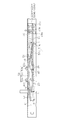
図1に示すように、車両用シートスライド装置1は、第1レールに相当する二つのロアレール30と、第2レールに相当する二つのアッパレール40と、二つの係止部材20と、二つのスプリング50とを備える。車両用シートスライド装置1は左右対称の構造を有するため、図1では車両用シートスライド装置1の片側の構造のみを示している。
<概略構成>
図1に示すように、車両用シートスライド装置1は、第1レールに相当する二つのロアレール30と、第2レールに相当する二つのアッパレール40と、二つの係止部材20と、二つのスプリング50とを備える。車両用シートスライド装置1は左右対称の構造を有するため、図1では車両用シートスライド装置1の片側の構造のみを示している。
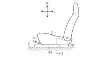
各ロアレール30は、長尺状であり、車両の前後方向に延出するとともに、車両フロア2上に固定されている。各ロアレール30の長手方向Lは車両の前後方向と同一の方向である。各アッパレール40は、対応するロアレール30に対して長手方向Lに相対移動可能に連結されている。
二つのロアレール30及び二つのアッパレール40は、長手方向Lに直交する幅方向Wでそれぞれ対をなして配設されている。図2に示すように、対をなすアッパレール40上には、乗員の着座部を形成するシート5が固定されている。
両アッパレール40間には、解除ハンドル60が連結されている。この解除ハンドル60は、両アッパレール40からシート5の前方に操作可能に延出している。この解除ハンドル60が車両フロア2に向かって押し下げ操作されることで、アッパレール40がシート5とともにロアレール30に対して移動可能となる。以下、車両用シートスライド装置1の構成について詳細に説明する。
<ロアレール>
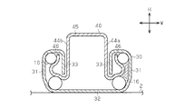
図3に示すように、ロアレール30は、ロア連結壁部32と、一対のロア側壁部31と、一対のロア折返し壁部33とを備える。
図3に示すように、ロアレール30は、ロア連結壁部32と、一対のロア側壁部31と、一対のロア折返し壁部33とを備える。
ロア連結壁部32は直方板状に形成されるとともに、車両フロア2上に固定的に設置されている。ロア側壁部31はロア連結壁部32における幅方向Wの両側から略直角に折り曲げられるように形成されている。また、ロア折返し壁部33は、ロア側壁部31の先端部がロアレール30の内側に折り曲げられるように形成されている。
図1に示すように、ロアレール30の両ロア折返し壁部33の基端、即ち上端には、それぞれの長手方向Lに沿って複数の四角形のロック孔33aが形成されている。これらロック孔33aは、一定間隔で形成されるとともに高さ方向Hにおける上方に開口している。高さ方向Hは、幅方向W及び長手方向Lに対して直交する方向である。
<アッパレール>
図3に示すように、アッパレール40は、アッパ連結壁部45と、第1及び第2のアッパ側壁部44a,44bと、二つのアッパ折返し壁部46とを備える。
図3に示すように、アッパレール40は、アッパ連結壁部45と、第1及び第2のアッパ側壁部44a,44bと、二つのアッパ折返し壁部46とを備える。
アッパ連結壁部45は、上記ロア連結壁部32と同様に直方板状に形成されている。両アッパ側壁部44a,44bは、アッパ連結壁部45における幅方向Wの両側から車両フロア2の方向に略直角に折り曲げられるように形成されている。また、アッパ折返し壁部46は、アッパ側壁部44a,44bの先端部がアッパレール40の外側に折り曲げられるように形成されている。
アッパレール40がロアレール30に組み付けられた状態においては、アッパレール40におけるアッパ側壁部44a,44b及びアッパ折返し壁部46間に、ロアレール30のロア折返し壁部33が位置する。このアッパレール40がロアレール30に組み付けられた状態においては、アッパレール40はロアレール30に沿って移動可能となるとともに、アッパレール40がロアレール30から当該ロアレール30と離間する方向に外れることが抑制される。
また、図1に示すように、アッパレール40における長手方向Lの中間には、それぞれの長手方向Lに並設された複数(この実施形態では3個)の係止爪用孔49a~49cが形成されている。隣接する係止爪用孔49a~49cの間隔は、隣接するロック孔33aの間隔と同一である。係止爪用孔49a~49cは、幅方向Wに貫通するとともに、高さ方向Hに長く、僅かに湾曲した略長方形状を有する。また、係止爪用孔49a~49cは、各アッパ側壁部44a,44bからアッパ連結壁部45の一部に及ぶ範囲に亘って形成されている。
さらに、各アッパ折返し壁部46の先端、即ち上端には、それぞれの長手方向Lに並設された複数(この実施形態では3個)の嵌入溝46aが各係止爪用孔49a~49cに対応する位置に形成されている。各嵌入溝46aは、上方に開口している。これら嵌入溝46a及び係止爪用孔49a~49cは、ロアレール30の複数のロック孔33aのうちの隣接する3個と合致可能な位置に配置されている。
また、各アッパ側壁部44a,44bには、幅方向Wに開口した支持孔47が形成されている。支持孔47は、係止爪用孔49a~49cと解除ハンドル60との間に形成されている。また、支持孔47と解除ハンドル60との間におけるアッパ連結壁部45には高さ方向Hに貫通した保持孔43aが形成されている。保持孔43aは長手方向Lに長い略楕円状に形成されている。
また、アッパ連結壁部45における長手方向Lに沿った保持孔43aの両側に高さ方向Hに貫通した保持孔43b,43cが形成されている。保持孔43b,43cは、保持孔43aより大きく、かつ長手方向Lに延出する略長方形状で形成されている。
<転動部材>
また、図3に示すように、各アッパ折返し壁部46及びこれに対向するロア側壁部31間には、前後一対の転動部材16が設けられている。アッパレール40は、ロアレール30との間で転動部材16を転動させる態様で、ロアレール30に対し長手方向Lに摺動自在に支持されている。
また、図3に示すように、各アッパ折返し壁部46及びこれに対向するロア側壁部31間には、前後一対の転動部材16が設けられている。アッパレール40は、ロアレール30との間で転動部材16を転動させる態様で、ロアレール30に対し長手方向Lに摺動自在に支持されている。
<係止部材>
図1に示すように、係止部材20は、ロアレール30及びアッパレール40間に形成される空間に長手方向Lに沿うように設置されている。
図1に示すように、係止部材20は、ロアレール30及びアッパレール40間に形成される空間に長手方向Lに沿うように設置されている。
図4(a)及び図5(b)に示すように、係止部材20は、本体部21と、2組の係止爪22aR~22cR,22aL~22cLと、支持部26と、入力部28とが一体的に形成されてなる。この係止部材20は金属板がプレス加工されることで製造される。
本体部21は長手方向Lに延出した略長方板状に形成されている。また、各係止爪22aR~22cR,22aL~22cLは本体部21における先端部23、即ち解除ハンドル60と反対側の端部に形成されている。係止爪22aR~22cR,22aL~22cLは、幅方向Wに突出した角棒状に形成されている。各係止爪22aR~22cR,22aL~22cLは、長手方向Lに沿って上記ロアレール30のロック孔33aと同一の間隔で配置されている。
図4(b)に示すように、係止部材20の支持部26は、本体部21に対して幅方向Wに延出するとともに、長手方向Lに沿って下側に向かって凸となるように僅かに湾曲した板状で形成されている。各支持部26は、上述した両支持孔47内に位置する。この支持孔47は、内在する支持部26の回動及び長手方向Lへの移動を許容する大きさで形成されている。
また、係止部材20には2つの嵌合穴29が形成されている。この嵌合穴29は、支持部26と係止爪22aR~22cR,22aL~22cLとの間における本体部21の長手方向Lに延びる各側面に形成されている。両嵌合穴29は幅方向Wに対向した位置に形成されている。
図4(c)に示すように、嵌合穴29は、係止部材20の中心側(図中の下方向)に向かうにつれて小さくなる幅Whを有するとともに円弧状の底を有する。すなわち、嵌合穴29における長手方向Lに沿って対向する2つの側面29bは幅方向Wに対して一定角度をなす圧力角として形成されている。嵌合穴29は、スリット状である。
なお、支持部26及び支持孔47は支持構造の一例である。
<スプリング>
図1に示すように、スプリング50は、弾性変形可能な1本の線材が略U字状に曲げられて形成されている。また、スプリング50は、ロアレール30及びアッパレール40間に形成される空間であって係止部材20の上面、即ちアッパ連結壁部45と対向する面に位置する。
<スプリング>
図1に示すように、スプリング50は、弾性変形可能な1本の線材が略U字状に曲げられて形成されている。また、スプリング50は、ロアレール30及びアッパレール40間に形成される空間であって係止部材20の上面、即ちアッパ連結壁部45と対向する面に位置する。
図5(a)及び図5(b)に示すように、スプリング50は、第1の弾性部51と、第2の弾性部52と、これら弾性部51,52間に保持部53とを有する。スプリング50における各部は幅方向Wの中心線に関して対称に形成されている。ここでは、特に必要がない限り、スプリング50における片側の各部についてのみ説明する。
図5(b)に示すように、保持部53は、車両上方に突出した2つの凸部53a,53bと、両凸部53a,53b間の湾曲部53cと、を有する。図5(a)に示すように、湾曲部53cは、長手方向Lにおいて外側に突出するように湾曲している。図6に示すように、凸部53a,53bは保持孔43b,43cにアッパレール40の内側から挿通される。これにより、スプリング50の長手方向Lにおける位置が保持される。
図5(a)及び図5(b)に示すように、第1の弾性部51は、嵌合部51aと、延出部51bとを備える。
延出部51bは、凸部53bから離間する方向(図中の右方向)に延出するとともに、同方向に向かうにつれて車両フロア2の方向(図5(b)の下方向)に向かう態様で傾斜している。延出部51bにおける先端には嵌合部51aが形成されている。この嵌合部51aは、延出部51bの延出方向に対して車両フロア2に向かって略直角に折り曲げられて形成されている。
延出部51bは、凸部53bから離間する方向(図中の右方向)に延出するとともに、同方向に向かうにつれて車両フロア2の方向(図5(b)の下方向)に向かう態様で傾斜している。延出部51bにおける先端には嵌合部51aが形成されている。この嵌合部51aは、延出部51bの延出方向に対して車両フロア2に向かって略直角に折り曲げられて形成されている。
第2の弾性部52は、凸部53aから離間する方向(図中の左方向)に延出するとともに、同方向に向かうにつれて車両フロア2の方向に向かう態様で傾斜している。幅方向Wにおいて対向する2つの第2の弾性部52における凸部53aと反対側の端部は、幅方向Wに延出する連結部52aを通じて連結されている。第2の弾性部52及び連結部52a内には、その上側から解除ハンドル60の先端部61が嵌め込まれる。
図1に示すように、スプリング50は、支持ピン55を通じてアッパレール40に支持される。支持ピン55は、スプリング50の両湾曲部53c間に位置している。これにより、支持ピン55がスプリング50によって保持される。そして、支持ピン55の先端は保持孔43aを通過する。これにより、支持ピン55がアッパレール40に支持される。
<スプリングの係止部材への取り付け時の作用>
次に、スプリング50の係止部材20への取り付け時の作用について説明する。
図5(a)の実線に示すように、スプリング50に対して外力が加わっていない状態においては、両延出部51bは長手方向Lに沿って延出している。このとき、幅方向Wにおける両第1の弾性部51間の距離は、幅方向Wにおける係止部材20の本体部21の長さより十分に小さく設定されている。
次に、スプリング50の係止部材20への取り付け時の作用について説明する。
図5(a)の実線に示すように、スプリング50に対して外力が加わっていない状態においては、両延出部51bは長手方向Lに沿って延出している。このとき、幅方向Wにおける両第1の弾性部51間の距離は、幅方向Wにおける係止部材20の本体部21の長さより十分に小さく設定されている。
スプリング50を係止部材20に取り付けるにあたって、まず、図5(a)の2点鎖線で示すように、両第1の弾性部51の嵌合部51aを互いに離間する方向に開くように嵌合部51aに対して外力が加えられる。これにより、図5(a)の2点鎖線に示すように、両第1の弾性部51は、嵌合部51aに向かうにつれて幅方向Wの距離が大きくなる。この状態から、両嵌合部51a間を結ぶ仮想的な直線が係止部材20の幅方向Wに沿う向きとした係止部材20が両嵌合部51a間に挿入される。
そして、各嵌合部51aが各嵌合穴29に対応した位置で、上記第1の弾性部51に対する外力が解除される。すると、両第1の弾性部51の復元力により、両第1の弾性部51は、互いに接近する方向に移動することで係止部材20の嵌合穴29に嵌合する。
ここで、図4(c)に示すように、嵌合穴29は底、即ち奥に向かうにつれて幅Whが小さくなるように形成されている。このため、嵌合部51aから嵌合穴29の側面29bに加わる力を大きくすることができる。これにより、嵌合部51aが嵌合穴29から外れづらくなる。
<シート位置調整に係る作用>
次に、シート5の位置を調整する際の作用について説明する。
図6の実線に示すように、解除ハンドル60に操作力が加えられていない状態においては、スプリング50からの付勢力を通じて、係止部材20の係止爪22aR~22cR,22aL~22cLは、スプリング50からの付勢力を通じてロアレール30のロック孔33a内に保持されている。このとき係止部材20は係止位置にある。これにより、ロアレール30に対するアッパレール40の移動が規制されている。この状態においては、第2の弾性部52は先端部61を支持している。
次に、シート5の位置を調整する際の作用について説明する。
図6の実線に示すように、解除ハンドル60に操作力が加えられていない状態においては、スプリング50からの付勢力を通じて、係止部材20の係止爪22aR~22cR,22aL~22cLは、スプリング50からの付勢力を通じてロアレール30のロック孔33a内に保持されている。このとき係止部材20は係止位置にある。これにより、ロアレール30に対するアッパレール40の移動が規制されている。この状態においては、第2の弾性部52は先端部61を支持している。
ここで、解除ハンドル60が持ち上げるように操作されると、図6の矢印Aに示すように、先端部61が第2の弾性部52の弾性力に抗して第2の弾性部52を図中の時計回りに回転される。第2の弾性部52が特定の位置まで到達すると、先端部61が係止部材20の入力部28に当接し、さらにその入力部28を車両フロア2の方向に押圧する。
これにより、図6の矢印B,Cに示すように、係止部材20がスプリング50(正確には第1の弾性部51)の弾性力に抗して反時計回りに回転を開始する。このとき、係止部材20は反時計回りに回動しつつ長手方向Lに沿って図中の右側に僅かに移動する。また、このとき、係止部材20における支持部26の下面が支持孔47の内で回転しながら摺動する。また、支持部26に対して支持孔47は十分大きく形成されているため、支持部26は長手方向Lに移動可能である。係止部材20の回動に伴い、延出部51bにおける凸部53b近傍の端部が曲げ変形することで延出部51bが長手方向Lに沿った方向となる。これにより、図6の矢印Dに示すように、係止爪22aR~22cR,22aL~22cLがロアレール30から離間し、係止爪22aR~22cR,22aL~22cLがロック孔33aから脱出する。このとき、ロアレール30に対するアッパレール40の移動が許容される。このとき係止部材20は解除位置にある。よって、シート5の車両前後方向における位置調整が可能となる。
この状態から、解除ハンドル60への操作力が解除されると、スプリング50の第1の弾性部51の復元力により、係止部材20が時計回りに回転しつつ、長手方向Lに沿って左方向に移動する。これにより、係止爪22aR~22cR,22aL~22cLがロック孔33aに嵌合した状態に戻る。
以上、説明した実施形態によれば、以下の効果を奏することができる。
(1)係止部材20は、両側壁部44a,44b間において長手方向Lに沿って移動可能かつ回動可能に支持されている。また、スプリング50は、係止部材20が係止位置となる方向に係止部材20を付勢するとともに、長手方向Lにおける係止部材20の位置を弾性的に保持する。この構成では、解除ハンドル60の操作に応じて、係止部材20は長手方向Lに移動しつつ回動可能である。従って、係止部材20は、明確な回転軸を有することなく回動可能に支持される。よって、より簡易な構成で係止部材20を回動可能に支持できる。また、この構成では、従来の回転軸及び軸通孔に要求される高い形状精度が不要となるため、容易に製造することができる。
(1)係止部材20は、両側壁部44a,44b間において長手方向Lに沿って移動可能かつ回動可能に支持されている。また、スプリング50は、係止部材20が係止位置となる方向に係止部材20を付勢するとともに、長手方向Lにおける係止部材20の位置を弾性的に保持する。この構成では、解除ハンドル60の操作に応じて、係止部材20は長手方向Lに移動しつつ回動可能である。従って、係止部材20は、明確な回転軸を有することなく回動可能に支持される。よって、より簡易な構成で係止部材20を回動可能に支持できる。また、この構成では、従来の回転軸及び軸通孔に要求される高い形状精度が不要となるため、容易に製造することができる。
(2)スプリング50の第1の弾性部51を通じて、係止部材20が係止位置となる方向に付勢される。よって、係止部材20に対して解除ハンドル60からの操作力が加わらない状態においては、係止部材20の係止位置が保持される。また、係止部材20に対して解除ハンドル60からの操作力が加わると、係止部材20は第1の弾性部51の弾性力に抗して長手方向Lに移動しつつ回動することで解除位置に移動する。
また、スプリング50の嵌合部51aを通じて係止部材20とスプリング50とが固定的に連結されている。このため、係止部材20が上記のように第1の弾性部51の弾性力に抗して長手方向Lに移動しつつ回動した場合であっても、係止部材20に対する外力が解除されることで、第1の弾性部51の復元力により嵌合部を通じて係止部材20をもとの係止位置に戻される。
(3)図5(a)に示すように、スプリング50を係止部材20に取り付けるにあたって、まず、スプリング50における嵌合部51aを、両延出部51b間で作用する弾性力に抗して離間させるように外力が加えられる。そして、両延出部51b間に係止部材20が挿入されていき、各嵌合部51aが対応する嵌合穴29に応じた位置に配置される。この状態から、上記外力を解除することで、各嵌合部51aが対応する嵌合穴29に進入する。これにより、スプリング50によって係止部材20が保持された状態となる。この構成では、より簡易な構成で、係止部材20をスプリング50に保持することができる。
(4)嵌合穴29における嵌合部51aが当接する側面29bは、嵌合穴29の底、即ち奥に向かうにつれて幅Whが小さくなるように傾斜している。各嵌合部51aが対応する嵌合穴29内に嵌合している際に、各嵌合部51aが対応する嵌合穴29の側面29bに付与する力が大きくなる。このため、各嵌合部51aが対応する嵌合穴29から離脱すること、ひいてはスプリング50が係止部材20から外れることが抑制される。
また、嵌合穴29の両側面29bを通じて、嵌合部51aを所望の位置に案内することができる。これによっても、各嵌合部51aが対応する嵌合穴29から離脱することが抑制される。
(5)係止部材20における嵌合穴29は、外側に向かうほど幅Whが大きくなように設定されている。このため、嵌合部51aを嵌合穴29内に入れ易くなる。
なお、上記実施形態は、これを適宜変更した以下の形態にて実施することができる。
なお、上記実施形態は、これを適宜変更した以下の形態にて実施することができる。
・上記実施形態においては、ロアレール30が車両フロア2に固定され、アッパレール40がロアレール30に対して相対移動可能に構成されていた。しかし、アッパレール40とロアレール30とを反対にしてもよい。
・上記実施形態における車両用シートスライド装置1を車両以外に適用してもよい。
・上記実施形態における係止部材20の係止爪22aR~22cR,22aL~22cL及び係止爪用孔49a~49cの数は適宜変更可能である。
・上記実施形態における係止部材20の係止爪22aR~22cR,22aL~22cL及び係止爪用孔49a~49cの数は適宜変更可能である。
・上記実施形態においては、スプリング50の両延出部51b間で作用する弾性力によりスプリング50が係止部材20に取り付けられている。しかし、スプリング50の先端と係止部材20とが連結されていれば、これ以外の方法で、スプリング50を係止部材20に取り付けてもよい。
・上記実施形態においては、第1の弾性部51及び第2の弾性部52が一体として形成されていたが、別体で形成してもよい。さらに、スプリング50において第2の弾性部52を省略してもよい。
・上記実施形態においては、支持構造は支持部26及び支持孔47から構成されていたが、支持構造の構成はこれに限らず、例えば、図7に示すように、支持構造は一対の支持部材48から構成されていてもよい。支持部材48は各アッパ折返し壁部46の一部がアッパレール40の内側に折り返された正方板状に形成されている。両支持部材48は、係止部材20の支持部26をその下面から係止部材20の回動及び長手方向Lへの移動を許容する態様で支持する。本構成では、支持部26及び支持孔47の省略が可能である。
Claims (5)
- 長尺状の第1レールと、
前記第1レールに対し前記第1レールの長手方向に沿って相対移動可能に連結される第2レールと、
前記第2レールを構成するものであって、前記長手方向に直交する幅方向に対面する第1及び第2の側壁部と、
前記第1及び第2の側壁部間に設けられるものであって、自身の回動位置に応じて前記第1レールに係止した係止位置と前記第1レールから離間した解除位置との間で回動する係止部材と、
前記第1及び第2の側壁部間に前記係止部材を前記長手方向に沿った移動を許容可能かつ前記幅方向に沿って延びる軸心を中心とした回動を許容可能に支持する支持構造と、
前記係止位置に向かう方向に前記係止部材を付勢するとともに、前記長手方向における前記係止部材の位置を弾性的に保持するスプリングと、を備えたシートスライド装置。 - 請求項1に記載のシートスライド装置において、
前記スプリングは、
前記第2レール内における前記係止部材及び前記第2レール間で弾性変形可能な弾性部と、
前記係止部材に固定的に連結された嵌合部と、を備えたシートスライド装置。 - 請求項2に記載のシートスライド装置において、
前記弾性部は、前記長手方向に沿って延出する二つの棒状の延出部を備え、
前記両延出部は、前記幅方向における前記係止部材の長さより小さい間隔で隣接して設けられるとともに、互いに離間する方向に弾性変形可能に構成され、
前記嵌合部は、前記弾性部の各先端部が前記係止部材の方向に屈曲される態様で形成されるとともに、前記係止部材における前記長手方向に延出する両側面に形成される嵌合穴内に前記両延出部間に作用する弾性力により位置可能に形成されるシートスライド装置。 - 請求項3に記載のシートスライド装置において、
前記嵌合穴における前記嵌合部が当接する側面は、前記嵌合穴の底に向かうにつれて幅が小さくなるように傾斜しているシートスライド装置。 - 請求項1に記載のシートスライド装置において、
前記支持構造は前記係止部材を構成するとともに前記幅方向の外側に向かって互いに反対側に延出する二つの支持部と、前記第1及び第2の側壁部にそれぞれ設けられる支持孔とから構成され、前記各支持部は対応する支持孔内において前記長手方向に移動可能かつ回動可能に構成されるシートスライド装置。
Applications Claiming Priority (2)
| Application Number | Priority Date | Filing Date | Title |
|---|---|---|---|
| JP2013-234199 | 2013-11-12 | ||
| JP2013234199A JP2015093578A (ja) | 2013-11-12 | 2013-11-12 | シートスライド装置 |
Publications (1)
| Publication Number | Publication Date |
|---|---|
| WO2015072226A1 true WO2015072226A1 (ja) | 2015-05-21 |
Family
ID=53057171
Family Applications (1)
| Application Number | Title | Priority Date | Filing Date |
|---|---|---|---|
| PCT/JP2014/074745 Ceased WO2015072226A1 (ja) | 2013-11-12 | 2014-09-18 | シートスライド装置 |
Country Status (2)
| Country | Link |
|---|---|
| JP (1) | JP2015093578A (ja) |
| WO (1) | WO2015072226A1 (ja) |
Cited By (1)
| Publication number | Priority date | Publication date | Assignee | Title |
|---|---|---|---|---|
| US20170341535A1 (en) * | 2016-05-26 | 2017-11-30 | Toyota Boshoku Kabushiki Kaisha | Seat sliding device |
Families Citing this family (5)
| Publication number | Priority date | Publication date | Assignee | Title |
|---|---|---|---|---|
| DE102016211029B4 (de) * | 2016-05-27 | 2019-05-23 | Adient Luxembourg Holding S.À R.L. | Längseinsteller für einen Fahrzeugsitz und Fahrzeugsitz |
| EP3546281B1 (en) * | 2018-03-16 | 2021-08-25 | TF-Metal Co., Ltd. | Seat slide device |
| JP7173884B2 (ja) * | 2019-01-25 | 2022-11-16 | トヨタ紡織株式会社 | スライド装置 |
| JP7186102B2 (ja) | 2019-01-25 | 2022-12-08 | トヨタ紡織株式会社 | スライド装置 |
| JP7173885B2 (ja) * | 2019-01-25 | 2022-11-16 | トヨタ紡織株式会社 | スライド装置 |
Citations (3)
| Publication number | Priority date | Publication date | Assignee | Title |
|---|---|---|---|---|
| JP2004322692A (ja) * | 2003-04-21 | 2004-11-18 | Gifu Auto Body Industry Co Ltd | 車両用シートトラックスライド装置におけるロック機構 |
| JP2013052844A (ja) * | 2011-09-06 | 2013-03-21 | Aisin Seiki Co Ltd | 車両用シートスライド装置 |
| JP2013052843A (ja) * | 2011-09-06 | 2013-03-21 | Aisin Seiki Co Ltd | 車両用シートスライド装置 |
-
2013
- 2013-11-12 JP JP2013234199A patent/JP2015093578A/ja active Pending
-
2014
- 2014-09-18 WO PCT/JP2014/074745 patent/WO2015072226A1/ja not_active Ceased
Patent Citations (3)
| Publication number | Priority date | Publication date | Assignee | Title |
|---|---|---|---|---|
| JP2004322692A (ja) * | 2003-04-21 | 2004-11-18 | Gifu Auto Body Industry Co Ltd | 車両用シートトラックスライド装置におけるロック機構 |
| JP2013052844A (ja) * | 2011-09-06 | 2013-03-21 | Aisin Seiki Co Ltd | 車両用シートスライド装置 |
| JP2013052843A (ja) * | 2011-09-06 | 2013-03-21 | Aisin Seiki Co Ltd | 車両用シートスライド装置 |
Cited By (3)
| Publication number | Priority date | Publication date | Assignee | Title |
|---|---|---|---|---|
| US20170341535A1 (en) * | 2016-05-26 | 2017-11-30 | Toyota Boshoku Kabushiki Kaisha | Seat sliding device |
| US10471853B2 (en) * | 2016-05-26 | 2019-11-12 | Toyota Boshoku Kabushiki Kaisha | Seat sliding device |
| US10703227B2 (en) | 2016-05-26 | 2020-07-07 | Toyota Boshoku Kabushiki Kaisha | Seat sliding device |
Also Published As
| Publication number | Publication date |
|---|---|
| JP2015093578A (ja) | 2015-05-18 |
Similar Documents
| Publication | Publication Date | Title |
|---|---|---|
| JP2015093578A (ja) | シートスライド装置 | |
| JP7173885B2 (ja) | スライド装置 | |
| JP5830954B2 (ja) | 車両用シートスライド装置 | |
| JP7186102B2 (ja) | スライド装置 | |
| JP7173884B2 (ja) | スライド装置 | |
| JP6488939B2 (ja) | 車両用シートスライド装置 | |
| JP6587893B2 (ja) | シートスライドアジャスタ | |
| JPS6025286B2 (ja) | 車両用屋根 | |
| JP5287128B2 (ja) | 車両用シートスライド装置 | |
| WO2013008630A1 (ja) | 車両用シートスライド装置 | |
| JP2017035914A (ja) | シートスライド装置 | |
| CN108349409A (zh) | 车用座椅滑动装置 | |
| JP5347651B2 (ja) | 車両用シートスライド装置 | |
| CN107921889A (zh) | 车辆座椅滑动装置 | |
| JP6094557B2 (ja) | シートスライド装置 | |
| JPH0576429A (ja) | スライドレール | |
| JP6094454B2 (ja) | シートスライド装置 | |
| JP2018052401A (ja) | シートスライド装置 | |
| JP6140546B2 (ja) | 乗物用シートのスライドレール装置 | |
| JP2016145025A (ja) | シートスライド装置 | |
| JP5974815B2 (ja) | 車両用シートスライド装置 | |
| JP6213149B2 (ja) | シートスライド装置 | |
| DE202014102504U1 (de) | Schwenkbedienelement mit multifunktionaler Blattfeder | |
| JP2009006643A (ja) | クリップ取付構造 | |
| JP6044507B2 (ja) | シートスライド装置 |
Legal Events
| Date | Code | Title | Description |
|---|---|---|---|
| 121 | Ep: the epo has been informed by wipo that ep was designated in this application |
Ref document number: 14862547 Country of ref document: EP Kind code of ref document: A1 |
|
| NENP | Non-entry into the national phase |
Ref country code: DE |
|
| 122 | Ep: pct application non-entry in european phase |
Ref document number: 14862547 Country of ref document: EP Kind code of ref document: A1 |