WO2015064189A1 - 冷蔵庫 - Google Patents
冷蔵庫 Download PDFInfo
- Publication number
- WO2015064189A1 WO2015064189A1 PCT/JP2014/072215 JP2014072215W WO2015064189A1 WO 2015064189 A1 WO2015064189 A1 WO 2015064189A1 JP 2014072215 W JP2014072215 W JP 2014072215W WO 2015064189 A1 WO2015064189 A1 WO 2015064189A1
- Authority
- WO
- WIPO (PCT)
- Prior art keywords
- door
- corner
- packing
- upper left
- refrigerator
- Prior art date
- Legal status (The legal status is an assumption and is not a legal conclusion. Google has not performed a legal analysis and makes no representation as to the accuracy of the status listed.)
- Ceased
Links
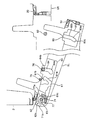
Images










Classifications
-
- F—MECHANICAL ENGINEERING; LIGHTING; HEATING; WEAPONS; BLASTING
- F25—REFRIGERATION OR COOLING; COMBINED HEATING AND REFRIGERATION SYSTEMS; HEAT PUMP SYSTEMS; MANUFACTURE OR STORAGE OF ICE; LIQUEFACTION SOLIDIFICATION OF GASES
- F25D—REFRIGERATORS; COLD ROOMS; ICE-BOXES; COOLING OR FREEZING APPARATUS NOT OTHERWISE PROVIDED FOR
- F25D23/00—General constructional features
- F25D23/08—Parts formed wholly or mainly of plastics materials
- F25D23/082—Strips
- F25D23/087—Sealing strips
-
- F—MECHANICAL ENGINEERING; LIGHTING; HEATING; WEAPONS; BLASTING
- F25—REFRIGERATION OR COOLING; COMBINED HEATING AND REFRIGERATION SYSTEMS; HEAT PUMP SYSTEMS; MANUFACTURE OR STORAGE OF ICE; LIQUEFACTION SOLIDIFICATION OF GASES
- F25D—REFRIGERATORS; COLD ROOMS; ICE-BOXES; COOLING OR FREEZING APPARATUS NOT OTHERWISE PROVIDED FOR
- F25D2323/00—General constructional features not provided for in other groups of this subclass
- F25D2323/02—Details of doors or covers not otherwise covered
- F25D2323/021—French doors
Definitions
- the present invention relates to a refrigerator.
- Patent Document 1 a refrigerator having a door that opens and closes an opening of a storage room is known. Such a conventional refrigerator is disclosed in Patent Document 1.
- the conventional refrigerator described in Patent Document 1 includes a packing for sealing between the door and the opening of the storage room when the door is closed.
- packing is generally provided on the four peripheral edges of the door having a rectangular shape in front view.
- packing may be provided on the portions of the left and right doors facing each other.
- the packing in the conventional refrigerator, in the process of forming the packing to be attached to the four peripheral edges of the door, there may be a problem that, for example, burrs are generated at the joint portion of the two-side packing joined at the corner portion. . Further, with respect to the packing of the facing doors of the double doors, the packing may be deformed by the action of friction generated between the packings when the door is closed.
- This invention is made
- the refrigerator of the present invention is attached to a storage chamber having an opening, a door having a rectangular shape in front view that opens and closes the opening, and a portion corresponding to the periphery of the opening of the door. And a packing that contacts a peripheral edge of the opening when the door is closed, and the packing has a portion corresponding to the corner of the door when the door is opened, and the corner and the other corner. It protrudes in the direction which leaves
- the packing includes a hollow portion that can be expanded and contracted in a direction away from or approaching the door, and the hollow portion of the portion corresponding to the corner portion of the door is different from the corner portion.
- a portion corresponding to the corner portion of the door is the corner portion when the door is opened. It protrudes in the direction away from the said door compared with the intermediate part with another corner
- the thickness of the corner portion of the packing when the door is opened increases, and the contact pressure of the corner portion of the packing when the door is closed increases. Therefore, it is suppressed that a gap is formed between the packing and the opening of the storage chamber at the corner of the door.
- the packing has a portion corresponding to the corner portion of the door locked by the locking portion that is separated from the door as compared with an intermediate portion between the corner portion and the other corner portion.
- a portion corresponding to the corner portion of the door protrudes in a direction away from the door as compared with an intermediate portion between the corner portion and another corner portion.
- a locking piece that is provided at a location where the packing is attached to the door and has a cross-sectional arrowhead shape protruding toward the door, and a substantially intermediate portion between the tip and the root of the locking piece.
- An engagement protrusion extending outward with respect to the peripheral surface of the provided locking piece, and a first recess formed between the arrowhead portion at the tip of the locking piece and the engagement protrusion.
- the first locking portion of the locking piece is locked in the region of the first cross-sectional shape, and the third disconnection is performed. It is characterized by locking the second locking portion of the locking piece in the area of the shape.
- the thickness of the corner of the packing when the door is opened increases, and the contact pressure of the corner of the packing when the door is closed increases. Therefore, it is suppressed that a gap is formed between the packing and the opening of the storage chamber at the corner of the door.
- a portion corresponding to the corner portion of the door of the packing which is provided at an attachment position of the packing with respect to the door, is locally movable in a direction away from or close to the door. And the packing is separated from the door in the opening process from the closed state of the door, the portion corresponding to the corner of the door is the corner and the other corner.
- the portion corresponding to the corner portion of the door is formed between the corner portion and the other corner portion. It protrudes in the direction which leaves
- the engagement portion is provided at a location where the packing is attached to the door and has a cross-sectional arrowhead shape protruding toward the door, and the tip of the lock piece A locking portion formed as a recess between the arrowhead portion and the root, and the locking piece to lock the packing and to move away from the corner of the door toward the other corner And an engagement groove whose cross-sectional shape changes to a fourth cross-sectional shape and a fifth cross-sectional shape, and the engagement groove has a shape in which the fourth cross-sectional shape is not caught by the locking piece, The locking portion of the locking piece is locked in a region having a fifth cross-sectional shape.
- the configuration of the present invention it is possible to provide a refrigerator capable of reliably sealing the opening of the storage room and improving the cooling efficiency.
- FIG. 8 is a vertical sectional side view of the packing shown in FIG. 7 taken along line VIII-VIII.
- FIG. 8 is a vertical sectional side view of the packing shown in FIG. 7 taken along line IX-IX.
- FIG. 11 is a vertical sectional side view taken along line XII-XII of the packing shown in FIG. 10.
- FIG. 11 is a vertical sectional side view taken along line XIII-XIII of the packing shown in FIG. 10. It is a partial back view which shows the upper left corner
- FIG. 15 is a vertical sectional side view taken along line XV-XV of the packing shown in FIG. 14.
- FIG. 15 is a vertical sectional side view taken along line XVI-XVI of the packing shown in FIG. 14. The state which opened the upper left door is made into the partial expansion top view which shows the opposing part of the left and right upper door of the refrigerator of 3rd Embodiment of this invention.
- the state which opened the upper left door is made into the partial expansion top view which shows the opposing part of the left and right upper door of the refrigerator of 3rd Embodiment of this invention.
- It is front sectional drawing which shows a part of cam mechanism of the door opening / closing mechanism of the refrigerator of 4th Embodiment of this invention.
- FIGS. 1 is a front view of the refrigerator when the door is closed
- FIG. 2 is a front view of the refrigerator when the upper door is opened
- FIG. 3 is a partial top view showing the door when the refrigerator is closed
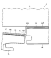
- FIG. It is a partial enlarged top view which shows the opposing part of a door.
- the left side in FIG. 1 will be described as the left side of the refrigerator
- the right side will be described as the right side of the refrigerator.
- the front side in the depth direction of FIG. 1 will be described as the front (front) of the refrigerator
- the back side in the depth direction of the paper will be described as the back (rear) of the refrigerator.
- the refrigerator 1 includes a main body housing 2 having a heat insulating structure as shown in FIGS. 1 and 2.
- the main body housing 2 includes a refrigeration chamber 3 in the upper stage as a storage room for food and the like, and a freezing room (not shown) in the lower stage.
- the refrigerator compartment 3 and the freezer compartment are partitioned by a partition 4.
- the refrigerator 1 includes an upper door 5 and a lower door 6 having a double-spread type heat insulating structure on the upper and lower sides of the front of the main body housing 2.
- the opening 3 a in front of the refrigerator compartment 3 is opened and closed by the upper door 5.
- the opening in front of the freezer compartment is opened and closed by the lower door 6.
- the upper door 5 is composed of an upper left door 5L and an upper right door 5R that are rectangular in front view.
- the lower door 6 includes a lower left door 6L and a lower right door 6R that form a front view rectangle.
- the upper left door 5L and the lower left door 6L each rotate in a double door manner with the axis extending in the vertical direction at the left end as the center of rotation, and the upper right door 5R and the lower right door 6R each rotate in the vertical direction at the right end in the vertical direction.
- Packing 10, 20 is attached to the part of the upper door 5 corresponding to the periphery of the opening 3 a of the refrigerator compartment 3.
- the packing is also attached to a portion of the lower door 6 corresponding to the periphery of the opening of the freezer compartment.
- the packing 10 is formed, for example, by extrusion molding of soft vinyl chloride, and has a rectangular (four sides) frame shape surrounding the periphery of the upper left door 5L.
- the packing 20 has a rectangular frame shape surrounding the periphery of the upper right door 5R.
- Each of the packings 10 and 20 includes upper side portions 10T and 20T extending left and right on the upper side, lower side portions 10B and 20B extending left and right on the lower side, outer side portions 10S and 20S extending vertically on the outer side in the lateral direction, It consists of four sides with opposing portions 10K and 20K extending vertically at the portions of the upper door 5 facing each other.
- the refrigerator compartment 3 is not provided with a partition portion at a position corresponding to a portion where the left and right upper doors 5 face each other as shown in FIG. 2, when the upper door 5 is closed, the facing portion 10K as shown in FIG. , 20K are in contact with each other, the opening 3a is sealed.
- FIGS. 5 is a partial rear view showing the upper part of the packing 10 of the upper left door 5L of the refrigerator 1
- FIG. 6 is a top view of the packing 10
- FIG. 7 is a partial top view showing the corners of the packing 10
- FIG. 9 is a vertical cross-sectional side view taken along line VIII-VIII of the packing 10
- FIG. 9 is a vertical cross-sectional side view taken along line IX-IX of the packing 10 shown in FIG. 8 and 9, the left side with respect to the packing 10 is the left upper door 5L side, and the right side with respect to the packing 10 is the opening 3a side of the refrigerator compartment 3.
- the packings 10 and 20 have the same structure with only left-right symmetry with respect to the portions facing each other, the packing 10 will be described below as a representative.
- the packing 10 has an outer side portion 10 ⁇ / b> S and an upper side portion 10 ⁇ / b> T joined to each other to form a corner portion 11, and the upper side portion 10 ⁇ / b> T and the facing portion 10 ⁇ / b> K are mutually connected.
- the corner portions 12 are formed by joining the end portions.
- the outer side portion 10S and the lower side portion 10B are joined to each other at the end portions, and the lower side portion 10B and the facing portion 10K are joined to each other at the end portions.
- these joining is made
- the packing 10 is attached to the upper left door 5L via the engaging portion 30.
- the engaging portion 30 includes a locking piece 31 and an engaging groove (not shown).
- the locking piece 31 is provided on the mounting surface 10a of the packing 10 with respect to the upper left door 5L, protrudes toward the upper left door 5L side (left in FIGS. 8 and 9) and opens. It has a cross-sectional arrowhead shape extending along the periphery of the portion 3a.
- the engaging groove is provided at a location corresponding to the locking piece 31 of the packing 10 in the upper left door 5L, and has a shape and a size capable of receiving and locking the locking piece 31.
- the packing 10 includes a hollow portion 14 that can expand and contract in a direction away from or approaching from the upper left door 5L (left and right lateral directions in FIGS. 8 and 9).
- the hollow portion 14 is divided into a plurality by the partition wall 15.
- a magnetized body holding portion 16 is formed at a location of the packing 10 closest to the opening 3a.
- the magnetized body holding portion 16 has a rectangular cross section surrounded by the partition wall 15 and the outer peripheral wall of the packing 10.
- the magnetized body holding portion 16 accommodates a magnetized body 17 having a rectangular cross section.
- the magnetized body 17 is composed of a flexible magnet or the like.
- the flexible magnet can be formed, for example, by kneading a granular ferromagnetic material in soft rubber and then magnetizing it.
- the magnetized body 17 is brought into close contact with the main body housing 2 at the periphery of the opening 3a at the upper side 10T, the lower side 10B, and the outer side 10S of the packing 10 by the magnetic force, and is opposed at the opposing part 10K.
- the upper right door 5R is in close contact with the facing portion 20K of the packing 20 of the upper right door 5R. Thereby, the opening 3a is sealed.
- the packing 10 corresponds to the upper corner portion of the upper left door 5L facing the upper right door 5R, that is, the corner portion 12 (the IX-IX line portion in FIG. ) Protrudes in a direction away from the upper left door 5L as compared with an intermediate portion between the corner portion 12 and another corner portion, for example, the corner portion 11 (the VIII-VIII line portion in FIG. 7 and FIG. 8). That is, when the packing 10 is joined to the end portions of the upper side portion 10T, the lower side portion 10B, the outer side portion 10S, and the facing portion 10K to form the rectangular frame shape shown in FIGS.
- the hollow part 14 of the corresponding part is formed in a state extending in a direction away from the upper left door 5L as shown in FIG. 9 as compared with the intermediate part with the corner part 11 shown in FIG.
- the upper side portion 10T of the packing 10 has a contact surface 10c (see FIGS. 8 and 9) with respect to the peripheral edge of the opening 3a as shown in FIGS. As it approaches, it extends with a gentle inclination so as to protrude in a direction away from the upper left door 5L (downward direction in FIGS. 6 and 7).
- FIGS. 10 is a partial rear view showing the upper left corner as viewed from the rear side of the upper left door of the refrigerator, and FIGS. 11, 12 and 13 are the XI-XI line, XII-XII line and XIII- of the packing shown in FIG. It is a vertical cross section side view in the XIII line. Since the basic configuration of this embodiment is the same as that of the first embodiment described with reference to FIGS. 1 to 9, the same components as those of the first embodiment are denoted by the same reference numerals as before. The description of the drawings and the description thereof will be omitted.
- the refrigerator 1 of the second embodiment includes an engagement groove 42 shown in FIGS. 10 to 13 and an engagement piece shown in FIGS. 11 to 13 as an engagement portion 40 between the upper side portion 10T of the packing 10 and the upper left door 5L.
- 41. 10 depicts a portion corresponding to the upper corner of the upper left door 5L facing the upper right door 5R, that is, a portion corresponding to the corner 12 of the packing 10 described above.
- the locking piece 41 is provided on the attachment surface 10a of the packing 10 with respect to the upper left door 5L, protrudes toward the upper left door 5L (left side in FIGS. 11 to 13), and extends along the periphery of the opening 3a. Make a shape.
- the locking piece 41 includes an engaging projection 43 at a substantially intermediate portion between the tip and the base in a direction protruding toward the upper left door 5L.
- the engagement protrusion 43 is shorter than the arrowhead portion at the tip of the locking piece 41 with respect to the direction along the mounting surface 10a toward the outer side with respect to the peripheral surface of the locking piece 41, that is, outward along the mounting surface 10a (see FIG. 11 to the vertical direction of FIG.
- the locking piece 41 includes a first locking portion 44 formed as a recess between the arrowhead portion at the tip and the engaging projection 43 on the tip side of the engaging projection 43. Furthermore, the locking piece 41 includes a second locking portion 45 formed as a recess between the base and the engaging projection 43 on the root side from the engaging projection 43.
- the engaging groove 42 is provided at a location corresponding to the locking piece 41 of the packing 10 in the upper left door 5L, and corresponds to the direction in which the packing 10 extends along the periphery of the opening 3a, that is, the corner portion 12 of the packing 10. It extends substantially linearly toward the corner 11 (see FIG. 5, left-right direction in FIG. 10).
- the engaging groove 42 has a cross-sectional shape 42a (first cross-sectional shape) in a region close to the corner 12 shown in FIG. 11 and a cross-sectional shape 42c (third) in an intermediate region between the corner 12 and the corner 11 shown in FIG.
- the cross-sectional shape is substantially the same.
- the cross-sectional shapes 42a and 42c have a shape in which the groove width of the opening edge 42w is narrower than the tip of the locking piece 41 and the width of the engaging projection 43, and the locking piece 41 is locked to hold the packing 10 firmly.
- the engagement groove 42 is different from the cross-sectional shapes 42a and 42c in the cross-sectional shape 42b (second cross-sectional shape, see FIG. 12) of the region between them in the extending direction.
- the groove width of the opening edge 42w is wider than the cross-sectional shapes 42a and 42c, and the engaging protrusion 43 of the locking piece 41 is difficult to interfere.
- the cross-sectional shape thereof changes to the cross-sectional shape 42a, the cross-sectional shape 42b, and the cross-sectional shape 42c.
- the cross-sectional shape of the engaging groove 42 changes gently in the region between the region of the cross-sectional shape 42a and the region of the cross-sectional shape 42b and the region between the region of the cross-sectional shape 42b and the region of the cross-sectional shape 42c.
- the locking piece 41 of the packing 10 is locked in the engaging groove 42 in which the corner portion 12 is separated from the upper left door 5L as compared with the intermediate portion between the corner portion 12 and the corner portion 11. Further, in the intermediate region between the corner portion 12 and the corner portion 11 having the cross-sectional shape 42 c of the engagement groove 42, the second engagement portion 45 of the engagement piece 41 of the packing 10 is engaged with the engagement groove 42. In the region having the cross-sectional shape 42 b of the engaging groove 42, the opening edge 42 w of the engaging groove 42 is unlikely to interfere with the engaging protrusion 43 of the locking piece 41, so that the packing 10 extends with a gentle inclination.
- the upper side portion 10T of the packing 10 is gently moved so that the contact surface 10c with respect to the peripheral edge of the opening 3a protrudes away from the upper left door 5L as the corner portion 11 approaches the corner portion 12. Inclined and extended.
- FIGS. 14 is a partial rear view showing the upper left corner as seen from the rear side of the upper left door of the refrigerator
- FIGS. 15 and 16 are vertical sectional side views of the packing shown in FIG. 14 taken along lines XV-XV and XVI-XVI, respectively. is there.
- FIGS. 17 and 18 are partially enlarged top views showing the facing portions of the left and right upper doors of the refrigerator, and show the state in which the upper left door is opened by 1 ° and 5 °, respectively. Since the basic configuration of this embodiment is the same as that of the first embodiment described with reference to FIGS. 1 to 9, the same components as those of the first embodiment are denoted by the same reference numerals as before. The description of the drawings and the description thereof will be omitted.
- the refrigerator 1 of the third embodiment includes an engaging groove 52 shown in FIGS. 14 to 16 as an engaging portion 50 between the upper side portion 10T of the packing 10 and the upper left door 5L, and an engaging piece shown in FIGS. 51. 14 depicts a portion corresponding to the upper corner of the upper left door 5L facing the upper right door 5R, that is, a portion corresponding to the corner 12 of the packing 10 described above.
- the locking piece 51 is provided on the mounting surface 10a of the packing 10 with respect to the upper left door 5L, protrudes toward the upper left door 5L (left side in FIGS. 15 and 16), and extends along the periphery of the opening 3a. Make a shape.
- the locking piece 51 includes a locking portion 54 formed as a recess between the arrowhead portion at the tip and the root.
- the engagement groove 52 has a cross-sectional shape 52a (fourth cross-sectional shape) in a region close to the corner 12 shown in FIG. 15 and a cross-sectional shape 52b (fifth cross-section) in an intermediate region between the corner 12 and the corner 11 shown in FIG.
- the cross-sectional shape is different.
- the cross-sectional shape 52b of the engaging groove 52 has a shape that holds the packing 10 firmly by locking the locking portion 54 of the locking piece 51 as shown in FIG.
- the cross-sectional shape 52a of the engaging groove 52 is wider than the cross-sectional shape 52b of the opening edge portion 52w, and the arrowhead portion at the tip of the locking piece 51 is not caught. ing. That is, the cross-sectional shape 52a makes the shape which enables the corner
- the cross-sectional shape of the engaging groove 52 changes from the corner portion 12 toward the corner portion 11 to the cross-sectional shape 52a and the cross-sectional shape 52b. Note that the cross-sectional shape of the engagement groove 52 gradually changes in a region between the cross-sectional shape 52a region and the cross-sectional shape 52b region.
- the packing 10 When the packing 10 is attached to the upper left door 5L using the engaging portion 50 having such a structure and the upper left door 5L is closed with respect to the opening 3a, the packing 10 is a portion of the corner portion 12, and the corner portion 12 and the corner portion. Both of the intermediate portions with the portion 11 are sandwiched between the upper left door 5L and the main body housing 2 and closely contact each other (see FIG. 4). The thickness in the direction from the upper left door 5L of the packing 10 toward the opening 3a (main body housing 2) is uniform overall.
- the corner portion 12 of the packing 10 is pulled toward the opening 3a by the magnetic force of the magnetized body 17 in the opening process.
- the packing 10 moves away from the corner 12 toward the corner 11 in a region between the cross-sectional shape 52a and the cross-sectional shape 52b of the engaging groove 52, the packing 10 is gradually locked by the locking portion 54.
- the degree increases.
- the corner portion 12 of the packing 10 moves locally in a direction away from the upper left door 5L as compared with the intermediate portion between the corner portion 12 and the corner portion 11, and FIGS. It becomes the form shown in.
- the position of the contact surface 10 c when the corner portion 12 of the packing 10 does not move locally in the direction away from the upper left door 5 ⁇ / b> L is drawn by a two-dot chain line. ing.
- the upper side portion 10T of the packing 10 is separated from the upper left door 5L as the contact surface 10c with respect to the periphery of the opening 3a approaches the corner portion 12 with respect to the corner portion 11. It extends with a gentle inclination so as to protrude in the direction.
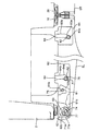
- FIG. 19 is a front sectional view showing a part of the cam mechanism of the door opening / closing mechanism of the refrigerator.
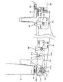
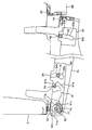
- 20 to 23 are plan views showing the operation of the cam mechanism of the door opening / closing mechanism. Since the basic configuration of this embodiment is the same as that of the first embodiment described with reference to FIGS. 1 to 9, the same components as those of the first embodiment are denoted by the same reference numerals as before. The description of the drawings and the description thereof will be omitted.
- the refrigerator 1 according to the fourth embodiment includes a cam mechanism shown in FIGS. 19 to 23 in a door opening / closing mechanism that allows the upper door 5 and the lower door 6 to rotate.
- the cam mechanism is provided with the same structure at the upper and lower portions of the upper left door 5L, upper right door 5R, lower left door 6L, and lower right door 6R.
- a description will be given by taking the cam mechanism provided at the lower part of the upper left door 5L as an example.
- FIG. 19 is a front cross-sectional view showing a part of the cam mechanism arranged at the lower part of the upper left door 5L, that is, a member group arranged at a position corresponding to the shaft side of the lower part of the upper left door 5L.
- a slide cam member 60 disposed on the shaft side and a guide cam 81 (see FIG. 20) disposed on the open side are attached to the upper left door 5L.
- a lock cam assembly 70 that engages with the slide cam member 60 and a guide pin 82 (see FIG. 20) that engages with the guide cam 81 are attached to the main body housing 2.
- the slide cam member 60 is made of a resin molded product, and bosses 60a and 60b projecting upward are formed on the upper surface, and screw holes 60c and 60d penetrating in the vertical direction are formed.
- the bosses 60a and 60b are fitted into boss holes (not shown) provided on the lower surface of the upper left door 5L, and tapping screws (not shown) are inserted into the screw holes 60c and 60d from below so that the slide cam member 60 is moved to the upper left door. It is attached to the lower surface of 5L.
- the slide cam member 60 is formed with a boss hole 60f for positioning a lock member 61 described later.
- a lock cam member 71 and an angle 72 are integrated by a screw 73, and engage with the slide cam member 60 to constitute a part of the cam mechanism.
- the lock cam member 71 is made of a resin molded product
- the angle 72 is made of a metal member to support the weight of the upper left door 5L.
- the screw holes 72a are formed in the angle 72 at three locations.
- An angle 72 that is, the lock cam assembly 70 is attached to the main body housing 2 by inserting a tapping screw into the screw hole 72a.
- a hinge pin 74, a lock pin 75, and an auxiliary guide pin 76 made of metal such as stainless steel are caulked and integrated with the angle 72, respectively.
- the hinge pin 74, the lock pin 75, and the auxiliary guide pin 76 pass through the lock cam member 71 and protrude upward.
- a pedestal 74 a is formed concentrically on the bottom of the hinge pin 74.
- the bottom surface 62a of the boss 62 formed on the slide cam member 60 rides on the pedestal 74a when the upper left door 5L is closed.
- the boss 62 has a stepped portion 62b that protrudes downward with respect to the bottom surface 62a.
- the inner peripheral side of the stepped portion 62b is formed along the pedestal portion 74a, and is chamfered in contact with the peripheral portion of the pedestal portion 74a.
- FIG. 20 is a plan view of the cam mechanism, showing a state in which the upper left door 5L is closed, and members attached to the main body housing 2 side are hatched.
- a lock member 61 is attached to the slide cam member 60.
- the lock member 61 is made of a resin molded product, and includes a boss (not shown) protruding upward on the upper surface.
- the lock member 61 is attached by a tapping screw (not shown) or the like by fitting this boss into a boss hole 60f (see FIG. 19) provided on the lower surface of the slide cam member 60.
- An arm portion 61 a is formed at one end of the lock member 61.
- the arm portion 61a is elastically deformed with respect to a load in a direction substantially perpendicular to the extending direction (a direction substantially parallel to the paper surface of FIG. 20).
- An engaging portion 61b that engages with the lock pin 75 is provided at the end of the arm portion 61a.
- the other end of the lock member 61 is provided with a restricting portion 61c that abuts against a stopper 71a formed on the lock cam member 71 (see FIG. 19) and restricts the rotation of the upper left door 5L.
- a long hole-like hinge groove 63 is formed as a recess recessed upward on the lower surface of one end of the slide cam member 60.
- a boss 62 having a cylindrical surface 62c centering on a hinge pin 74 at the second locking position described later is formed.
- a rib 77 having a cylindrical concave surface 77a concentric with the hinge pin 74 is provided around the hinge pin 74 of the lock cam member 71 so as to protrude upward.
- An auxiliary guide groove 64 that is bent in an L shape is formed as a concave portion that is depressed upward on the lower surface of the center portion of the opening 3 a than the hinge groove 63 of the slide cam member 60.
- the auxiliary guide groove 64 has a guide portion 64a for relatively guiding the auxiliary guide pin 76 from a first locking position to a second locking position, which will be described later, and a clearance for relatively releasing the auxiliary guide pin 76 at the second locking position. Part 64b.
- the guide cam 81 attached to the open side of the upper left door 5L is made of a resin molded product and includes a bent guide groove 83.
- a stainless steel guide pin 82 engaging with the guide groove 83 is attached to the main body housing 2 while being supported by an angle (not shown).
- the guide groove 83 includes a guide portion 83a that relatively guides the guide pin 82 from a first locking position to a second locking position, which will be described later, and an escape portion 83b that relatively releases the guide pin 82 at the second locking position. And an arc portion 83c extending from the end of the guide portion 83a in the circumferential direction around the hinge pin 74 at the first locking position.
- each part of the cam mechanism should be originally represented by a broken line, but is represented by a solid line for convenience. Further, the hatched portion indicates the member disposed on the main body housing 2 side as described above.
- FIG. 20 shows a state in which the upper left door 5L is closed.
- the hinge pin 74 is locked to one end of the hinge groove 63, and the cam mechanism takes the first locking position.
- the guide pin 82 is disposed at the end of the guide portion 83 a of the guide groove 83.
- An auxiliary guide pin 76 is disposed at the end of the guide portion 64 a of the auxiliary guide groove 64.
- the upper left door 5L is rotated in the closing direction with the hinge pin 74 as a rotation shaft at the first locking position. Can move. Therefore, the upper left door 5L at the first locking position can be reliably closed.
- the auxiliary guide pin 76 and the guide portion 64a are not in the first locking position so that the guide portion 64a of the auxiliary guide groove 64 and the auxiliary guide pin 76 abut and the rotation of the upper left door 5L is not restricted. Between the gaps, gaps A1 and A2 in the longitudinal direction and the width direction of the groove are provided.
- the lock pin 75 is engaged with the engagement portion 61b of the lock member 61, and the upper left door 5L is biased in the direction of the upper right door 5R by the elastic force of the arm portion 61a. Accordingly, a predetermined amount of gap between the upper left door 5L and the upper right door 5R is securely held, and floating of the upper left door 5L due to a gap for fitting between the hinge pin 74 and the hinge groove 63 is prevented. . Therefore, the cam mechanism maintains the state of the first locking position and further ensures a closed and sealed state with respect to the opening 3a of the upper left door 5L.
- the hinge pin 74 cannot be rotated as an axis. For this reason, the hinge pin 74 is relatively guided to the hinge groove 63 and the guide pin 82 is guided to the guide portion 83a. Further, the relative movement of the auxiliary guide pin 76 is not restricted by the gap A2 provided in the guide portion 64a of the auxiliary guide groove 64.
- the upper left door 5L slides in a direction away from the upper right door 5R (left direction in FIG. 20) while rotating. Therefore, the packing 10 provided in the upper left door 5L is separated from the packing 20 provided in the upper right door 5R. As a result, the sliding of the packings 10 and 20 is avoided to prevent damage, and the opening operating force is reduced by reducing sliding friction.
- the step 62b (see FIG. 19) of the boss 62 rides on the pedestal 74a (see FIG. 19), and the upper left door 5L is lifted. Therefore, the upper left door 5L can be opened only when an operating force for pulling the upper left door 5L is applied, and the upper left door 5L is not easily opened from the closed state by the elastic force of the packing 10.
- the arm portion 61a of the lock member 61 is elastically deformed, and the disengagement between the lock pin 75 and the engagement portion 61b is started. At this time, when the hand holding the upper left door 5L is released, the upper left door 5L returns to the state shown in FIG. 20 by the elastic force of the arm portion 61a. Therefore, the lock member 61 and the lock pin 75 have a self-closing function so that the upper left door 5L can be reliably closed.
- the guide pin 82 and the auxiliary guide pin 76 are disposed at the intersecting positions of the guide portions 83a and 64a and the escape portions 83b and 64b of the guide groove 83 and the auxiliary guide groove 64, respectively.
- the escape portions 83b and 64b of the guide groove 83 and the auxiliary guide groove 64 are formed in an arc shape centered on the hinge pin 74 at the second locking position, and the guide pin 82 and the auxiliary guide pin 76 are relatively released and the upper left door. The 5L rotation is guided to securely hold the second locking position.
- the cylindrical surface 62c of the boss 62 slides at two locations on the concave surface 77a of the rib 77 as shown in FIG. 22, and the boss 62 cannot move in the longitudinal direction of the hinge groove 63. Thereby, the cam mechanism maintains the state of the second locking position, and the upper left door 5L is pivotally supported.
- the concave surface 77a of the rib 77 only needs to be able to guide the boss 62, and may be formed by a plurality of pins arranged on an arc concentric with the hinge pin 74, for example, instead of the rib 77.
- the upper left door 5L rotates while the guide groove 83 relatively guides the guide pin 82 and the cam mechanism holds the second locking position.
- the guide portion 64 a of the auxiliary guide groove 64 is provided with gaps A 1 and A 2 (see FIG. 20) between the guide portion 64 a and the auxiliary guide pin 76, the engagement between the relief portion 83 b of the guide groove 83 and the guide pin 82. After that, the engagement between the relief portion 64b of the auxiliary guide groove 64 and the auxiliary guide pin 76 is started.
- the distance between the guide pin 82 and the auxiliary guide pin 76 and the distance between the corresponding relief portions 83b and 64b coincide with each other due to the mounting error of the guide cam 81 and the auxiliary guide pin 76 and the dimensional error of the guide cam. May not.
- the guide groove 83 and the guide pin 82 and the engagement between the auxiliary guide groove 64 and the auxiliary guide pin 76 occur at the same time, for example, the guide groove 83 and the guide pin 82 And the upper left door 5L cannot be opened smoothly.
- the clearance between the escape portion 64b and the auxiliary guide pin 76 is increased, and the engagement between the escape portion 83b and the guide pin 82 is released.
- the gap between the escape portion 64b and the auxiliary guide pin 76 is reduced.
- the restricting portion 61c of the lock member 61 comes into contact with a stopper 71a formed on the lock cam member 71 (see FIG. 19), and the rotation range of the upper left door 5L is restricted. Further, the upper left door 5L can be closed by an operation reverse to the operation shown in FIGS. 20 to 23 described above.
- the upper left door 5L when closing the upper left door 5L, when the cam mechanism shifts from the second locking position to the first locking position, the upper left door 5L rotates and approaches the upper right door 5R (right in FIG. 20). Direction). Therefore, the packing 10 provided on the upper left door 5L comes into contact with the packing 20 provided on the upper right door 5R. With this configuration, even if the refrigerator compartment 3 is not provided with a partition at a location corresponding to the portion where the upper left door 5L and the upper right door 5R face each other, the facing portion is sealed and cold air leaks to the outside. Can be prevented.
- the present embodiment has the structure described as the third embodiment regarding the attachment of the packing 10 to the upper left door 5L (see FIGS. 14 to 18). That is, in the process of opening the upper left door 5L, the packing 10 moves in a direction in which the corner portion 12 moves locally away from the upper left door 5L as compared with the intermediate portion between the corner portion 12 and the corner portion 11. 15, 17, and 18.
- the upper left door 5L If the degree of close contact with the upper right door 5R is relatively high, when the upper left door 5L is opened, the upper left door 5L may be caught and the upper right door 5R may be opened. Thereby, the outflow amount of the cold air to the outside of the refrigerator compartment 3 increases, and the energy saving of the refrigerator 1 may be hindered.
- the corner portion 12 of the packing 10 is locally moved away from the upper left door 5L as compared with the intermediate portion between the corner portion 12 and the corner portion 11 (FIG. 15). 17 and 18), when the upper left door 5L is opened, the contact pressure between the upper left door 5L and the upper right door 5R is reduced, and the upper right door 5R is opened by being caught by the upper left door 5L. It is possible to suppress.
- the upper side portion 10T of the packing 10 of the refrigerator 1 is a contact surface with respect to the periphery of the opening portion 3a at the corner portion 12 corresponding to the corner portion of the upper left door 5L when the upper left door 5L is opened.
- 10c protrudes in a direction away from the upper left door 5L as compared with an intermediate portion between the corner portion 12 and the corner portion 11 which is another corner portion.
- the packing 10 demonstrated in 1st Embodiment is equipped with the hollow part 14 which can be expanded-contracted in the direction which leaves
- the corner 12 is formed so as to extend in a direction away from the upper left door 5L as compared with the intermediate portion between the corner 12 and the other corner 11.
- a portion of the corner portion 12 corresponding to the corner portion of the upper left door 5L protrudes in a direction away from the upper left door 5L as compared with an intermediate portion between the corner portion 12 and the corner portion 11 which is another corner portion.
- the thickness of the corner portion 12 of the packing 10 when the upper left door 5L is opened increases, and the corner portion 12 of the packing 10 when the upper left door 5L is closed.
- Contact pressure increases. Therefore, it is possible to suppress the formation of a gap between the packing 10 and the opening 3a of the refrigerator compartment 3 at the corner of the upper left door 5L.
- the refrigerator 1 demonstrated in 2nd Embodiment is provided in the attachment location with respect to the upper left door 5L of the packing 10, and can lock the packing 10 with respect to the upper left door 5L in the several places of the direction which leaves
- the corner portion 12 of the packing 10 corresponding to the corner portion of the upper left door 5L is the corner portion 12 and the other corner portion.
- the corner portion corresponding to the corner portion of the upper left door 5L is locked by the first locking portion 44 that is separated from the upper left door 5L compared to the intermediate portion with the upper left door 11L.
- 12 part protrudes in the direction which leaves
- the refrigerator 1 includes a locking piece 41 having a cross-sectional arrowhead shape that is provided on the mounting surface 10a of the packing 10 and protrudes toward the upper left door 5L, and a substantially intermediate portion between the tip and the root of the locking piece 41.
- the engaging projection 43 extending outward with respect to the peripheral surface of the locking piece 41 provided on the first portion is formed as a recess between the arrowhead portion at the tip of the locking piece 41 and the engaging projection 43.
- the engaging groove 42 has a cross-sectional shape 42a, a cross-sectional shape 42b, and a cross-sectional shape 42c, the cross-sectional shape of which changes from the portion 12 toward the corner 11 which is another corner. And the engaging groove 42 latches the 1st latching
- the thickness of the corner 12 of the packing 10 when the upper left door 5L is opened increases, and the corner 12 of the packing 10 when the upper left door 5L is closed.
- the contact pressure increases. Therefore, it is possible to suppress the formation of a gap between the packing 10 and the opening 3a of the refrigerator compartment 3 at the corner of the upper left door 5L.
- the refrigerator 1 demonstrated in 3rd Embodiment is provided in the attachment location with respect to the upper left door 5L of the packing 10, and the part of the corner
- An engaging portion 50 is provided that is movable in the direction of leaving or approaching and engages, and when the packing 10 is separated from the upper left door 5L in the opening process from the closed state of the upper left door 5L, the upper left door 5L of the packing 10
- the portion of the corner portion 12 corresponding to the corner portion of the upper left portion moves locally in the direction away from the upper left door 5L as compared with the intermediate portion between the corner portion 12 and the corner portion 11 which is the other corner portion.
- the portion of the corner portion 12 corresponding to the corner portion of the upper left door 5L is away from the upper left door 5L as compared with the intermediate portion between the corner portion 12 and the other corner portion 11. Protruding.
- the engaging portion 50 is provided on the mounting surface 10a of the packing 10 and has a locking piece 51 having a cross-sectional arrowhead shape protruding toward the upper left door 5L, and a front end of the locking piece 51.
- An engaging portion 54 formed as a recess between the arrowhead portion and the base, and the engaging piece 51 are engaged to hold the packing 10, and a cross section thereof as it is separated from the corner portion 12 toward the corner portion 11.
- the engaging groove 52 has a cross-sectional shape 52a and a cross-sectional shape 52b.
- the engaging groove 52 has a cross-sectional shape 52a that does not catch the arrowhead at the tip of the locking piece 51, and locks the locking portion 54 of the locking piece 51 in the region of the cross-sectional shape 52b.
- the thickness of the corner portion 12 of the packing 10 when the upper left door 5L is opened increases.
- the contact pressure of the corner portion 12 of the packing 10 at the time of closing of 5 L increases. Therefore, it is possible to suppress the formation of a gap between the packing 10 and the opening 3a of the refrigerator compartment 3 at the corner of the upper left door 5L.
- the opening part 3a ahead of the refrigerator compartment 3 can be sealed reliably, and the refrigerator 1 which can improve cooling efficiency can be provided.
- the corner portion 12 of the upper side portion 10T of the packing 10 corresponding to the upper corner portion of the upper left door 5L facing the upper right door 5R has been described as an example.
- the application target of the invention is not limited to the location, and may be another location.
- the application target of the present invention may be the corner 11 of the upper side 10T, or the other side of the lower side 10B, the outer side 10S, or the facing portion 10K.
- the application target of the present invention is not limited to application to only one of the four corners, and may be applied to a plurality of, for example, all four. Furthermore, the present invention may be applied to the lower door 6.
- the opening and closing direction of the door is not limited, and the present invention can be applied to a door that opens and closes in either the left-right direction or the up-down direction.
- the present invention can be used in a refrigerator.
Landscapes
- Engineering & Computer Science (AREA)
- Chemical & Material Sciences (AREA)
- Combustion & Propulsion (AREA)
- Physics & Mathematics (AREA)
- Mechanical Engineering (AREA)
- Thermal Sciences (AREA)
- General Engineering & Computer Science (AREA)
- Refrigerator Housings (AREA)
Abstract
冷蔵庫1は、開口部3aを有する冷蔵室3と、開口部3を開閉する正面視矩形をなす上扉5と、上扉5の開口部3aの周縁に対応する部分に取り付けられ上扉5の閉鎖時に開口部3aの周縁に接触するパッキン10、20と、を備え、左上扉5Lの開放時において、パッキン10の、左上扉5Lの角部に対応する角部12の部分が角部12と他の角部11との中間部分と比較して左上扉5Lから離れる方向に突出する。
Description
本発明は冷蔵庫に関する。
従来、貯蔵室の開口部を開閉する扉を備えた冷蔵庫が知られている。このような従来の冷蔵庫が特許文献1に開示されている。
特許文献1に記載された従来の冷蔵庫は扉の閉鎖状態において扉と貯蔵室の開口部との間を密閉させるためのパッキンを備えている。例えば、片開き式の扉の場合、一般的に正面視矩形をなす扉の周縁四辺にパッキンが設けられる。また例えば、特許文献1に記載された所謂観音開き式の扉の場合のように、左右の扉の互いに対向し合う部分にもパッキンが設けられることがある。このような構成により、庫内の空気を外部に逃がしたり、外部の空気が庫内へ侵入したりすることを防止して、庫内の温度や湿度を所定の状態に保持できるようにしている。
しかしながら、上記従来の冷蔵庫では、扉の周縁四辺に取り付けるパッキンを形成する工程において、角部で接合する二辺のパッキンのその接合部に、例えばバリが発生するなどの不具合が生じることがあった。また、観音開き式の左右の扉の互いに対向し合う部分のパッキンについては、扉の閉鎖時におけるパッキンどうしの間で生じる摩擦の作用によりパッキンが変形することがあった。
これらの不具合により、扉の角部においてパッキンと貯蔵室の開口部との間に隙間ができてしまうことがあった。したがって、貯蔵室を扉で密閉することができず、冷蔵庫の冷却性能が低下する虞があるといった問題があった。
本発明は上記の点に鑑みなされたものであり、貯蔵室の開口部を確実に密閉することができ、冷却効率を向上させることが可能な冷蔵庫を提供することを目的とする。
上記の課題を解決するため、本発明の冷蔵庫は、開口部を有する貯蔵室と、前記開口部を開閉する正面視矩形をなす扉と、前記扉の前記開口部の周縁に対応する部分に取り付けられ前記扉の閉鎖時に前記開口部の周縁に接触するパッキンと、を備え、前記パッキンは、前記扉の開放時において、前記扉の角部に対応する部分が前記角部と他の角部との中間部分と比較して前記扉から離れる方向に突出することを特徴としている。
この構成によれば、扉の開放時において、パッキンの角部の扉から貯蔵室の開口部に向かう方向の厚みが増加する。さらに、扉の閉鎖時において、パッキンの角部の開口部との接触圧力が増加する。したがって、扉の角部においてパッキンと貯蔵室の開口部との間に隙間ができることが抑制される。
また、上記構成の冷蔵庫において、前記パッキンは、前記扉から離れる方向または近づく方向に伸縮可能な中空部を備え、前記扉の前記角部に対応する部分の前記中空部が、前記角部と他の角部との中間部分と比較して前記扉から離れる方向に伸びた状態にして形成されることにより、前記扉の開放時において、前記扉の前記角部に対応する部分が前記角部と他の角部との中間部分と比較して前記扉から離れる方向に突出することを特徴としている。
この構成によれば、パッキンの中空部の構造を利用することで、扉の開放時におけるパッキンの角部の厚みが増加し、扉の閉鎖時におけるパッキンの角部の接触圧力が増加する。したがって、扉の角部においてパッキンと貯蔵室の開口部との間に隙間ができることが抑制される。
また、上記構成の冷蔵庫において、前記パッキンの前記扉に対する取り付け箇所に設けられ前記パッキンを前記扉から離れる方向または近づく方向の複数箇所で前記扉に対して係止可能にする係止部を備え、前記パッキンは、前記扉の前記角部に対応する部分が、前記角部と他の角部との中間部分と比較して前記扉から離れる形態となる前記係止部に係止されることにより、前記扉の開放時において、前記扉の前記角部に対応する部分が前記角部と他の角部との中間部分と比較して前記扉から離れる方向に突出することを特徴としている。
また、上記構成の冷蔵庫において、前記パッキンの前記扉に対する取り付け箇所に設けられ前記扉に向かって突出する断面矢尻形状をなす係止片と、前記係止片の先端と根本との略中間部に設けられた前記係止片の周面に対して外側に向かって延びる係合突起と、前記係止片の先端の前記矢尻の部分と前記係合突起との間で凹部として形成された第1係止部と、前記係止片の根元と前記係合突起との間で凹部として形成された第2係止部と、前記係止片を係止して前記パッキンを保持するとともに前記扉の前記角部から他の角部に向かって離れるに連れてその断面形状が第1断面形状、第2断面形状、第3断面形状と変化する係合溝と、を備え、前記係合溝は、前記第1断面形状の領域で前記係止片の前記第1係止部を係止し、前記第3断面形状の領域で前記係止片の前記第2係止部を係止することを特徴としている。
これらの構成によれば、パッキンの扉に対する取り付け構造を利用することで、扉の開放時におけるパッキンの角部の厚みが増加し、扉の閉鎖時におけるパッキンの角部の接触圧力が増加する。したがって、扉の角部においてパッキンと貯蔵室の開口部との間に隙間ができることが抑制される。
また、上記構成の冷蔵庫において、前記パッキンの前記扉に対する取り付け箇所に設けられ前記パッキンの前記扉の前記角部に対応する部分を局部的に前記扉から離れる方向または近づく方向に移動可能にして係合する係合部を備え、前記パッキンは、前記扉の閉鎖状態からの開放過程おいて前記扉から離隔するとき、前記扉の前記角部に対応する部分が、前記角部と他の角部との中間部分と比較して局部的に前記扉から離れる方向に移動することにより、前記扉の開放時において、前記扉の前記角部に対応する部分が前記角部と他の角部との中間部分と比較して前記扉から離れる方向に突出することを特徴としている。
また、上記構成の冷蔵庫において、前記係合部が、前記パッキンの前記扉に対する取り付け箇所に設けられ前記扉に向かって突出する断面矢尻形状をなす係止片と、前記係止片の先端の前記矢尻の部分と根元との間で凹部として形成された係止部と、前記係止片を係止して前記パッキンを保持するとともに前記扉の前記角部から他の角部に向かって離れるに連れてその断面形状が第4断面形状、第5断面形状と変化する係合溝と、を備え、前記係合溝は、前記第4断面形状が前記係止片に引っ掛からない形状をなし、前記第5断面形状の領域で前記係止片の前記係止部を係止することを特徴としている。
これらの構成によれば、扉の開放時にパッキンの角部が変位するというパッキンの構造を利用することで、扉の開放時におけるパッキンの角部の厚みが増加し、扉の閉鎖時におけるパッキンの角部の接触圧力が増加する。したがって、扉の角部においてパッキンと貯蔵室の開口部との間に隙間ができることが抑制される。
本発明の構成によれば、貯蔵室の開口部を確実に密閉することができ、冷却効率を向上させることが可能な冷蔵庫を提供することができる。
以下、本発明の実施形態を図1~図23に基づき説明する。
<第1実施形態>
最初に、本発明の第1実施形態の冷蔵庫について、図1~図4を用いてその構造の概略を説明する。図1は冷蔵庫の扉閉鎖時の正面図、図2は冷蔵庫の上扉開放時の正面図、図3は冷蔵庫の扉閉鎖時の扉部分を示す部分上面図、図4は冷蔵庫の左右の上扉の対向部分を示す部分拡大上面図である。なお、図1に矢印で示したとおり、図1における左方を冷蔵庫の左側とし、右方を冷蔵庫の右側として説明する。また、図1の紙面奥行き方向手前側を冷蔵庫の正面(前方)とし、紙面奥行き方向奥側を冷蔵庫の背面(後方)として説明する。
最初に、本発明の第1実施形態の冷蔵庫について、図1~図4を用いてその構造の概略を説明する。図1は冷蔵庫の扉閉鎖時の正面図、図2は冷蔵庫の上扉開放時の正面図、図3は冷蔵庫の扉閉鎖時の扉部分を示す部分上面図、図4は冷蔵庫の左右の上扉の対向部分を示す部分拡大上面図である。なお、図1に矢印で示したとおり、図1における左方を冷蔵庫の左側とし、右方を冷蔵庫の右側として説明する。また、図1の紙面奥行き方向手前側を冷蔵庫の正面(前方)とし、紙面奥行き方向奥側を冷蔵庫の背面(後方)として説明する。
冷蔵庫1は、図1及び図2に示すように断熱構造の本体筐体2を備える。本体筐体2はその内部に食品等の貯蔵室として上段に冷蔵室3を備え、下段に不図示の冷凍室を備える。冷蔵室3と冷凍室との間は仕切り部4によって仕切られる。
冷蔵庫1は本体筐体2の前方の上下それぞれに観音開き式の断熱構造の上扉5及び下扉6を備える。冷蔵室3の前方の開口部3aは上扉5によって開閉される。冷凍室の前方の開口部は下扉6によって開閉される。
上扉5は正面視矩形をなす左上扉5L及び右上扉5Rからなる。下扉6は正面視矩形をなす左下扉6L及び右下扉6Rからなる。左上扉5L及び左下扉6Lは各々左端の上下方向に延びる軸線を回転中心とし、右上扉5R及び右下扉6Rは各々右端の上下方向に延びる軸線を回転中心として観音開き式に回動する。
上扉5の、冷蔵室3の開口部3aの周縁に対応する部分にはパッキン10、20が取り付けられる。なお、パッキンは下扉6の、冷凍室の開口部の周縁に対応する部分にも取り付けられる。
パッキン10は例えば軟質塩化ビニルの押し出し成型により形成され、左上扉5Lの周縁を囲む長方形(四辺)の枠形状をなす。同様に、パッキン20は右上扉5Rの周縁を囲む長方形の枠形状をなす。パッキン10、20は各々、上側で左右に延びる上辺部10T、20Tと、下側で左右に延びる下辺部10B、20Bと、横方向の外側で上下に延びる外辺部10S、20Sと、左右の上扉5の互いに対向し合う部分で上下に延びる対向部10K、20Kとの四辺からなる。
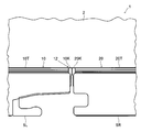
上扉5を閉鎖すると、上辺部10T、20Tと、下辺部10B、20Bと、外辺部10S、20Sとが冷蔵室3の開口部3aの周縁に接触する(上辺部10T、20Tを描画した図3参照)。冷蔵室3が図2に示すように左右の上扉5の互いに対向し合う部分に対応する箇所に仕切り部を備えていないので、上扉5の閉鎖時、図4に示すように対向部10K、20Kが互いに接触することにより開口部3aが密閉される。
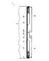
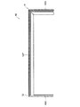
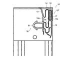
続いて、パッキン10、20の詳細な構成について、図5~図9を用いて説明する。図5は冷蔵庫1の左上扉5Lのパッキン10の上部を示す部分背面図、図6はパッキン10の上面図、図7はパッキン10の角部を示す部分上面図、図8は図7に示すパッキン10のVIII-VIII線における垂直断面側面図、図9は図7に示すパッキン10のIX-IX線における垂直断面側面図である。なお、図8及び図9において、パッキン10に対する左方が左上扉5L側であり、パッキン10に対する右方が冷蔵室3の開口部3a側である。また、パッキン10、20は互いに対向し合う部分に関して左右対称をなすだけで同じ構造であるので、以下パッキン10を代表として掲げて説明する。
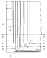
パッキン10は、図5及び図6に示すように外辺部10Sと上辺部10Tとが互いの端部どうしで接合されて角部11を形成し、上辺部10Tと対向部10Kとが互いの端部どうしで接合されて角部12を形成する。図示しないが、パッキン10の下側においても、外辺部10Sと下辺部10Bとが互いの端部どうしで接合され、下辺部10Bと対向部10Kとが互いの端部どうしで接合される。なお、これらの接合は超音波等を利用した溶着などによりなされる。
パッキン10は係合部30を介して左上扉5Lに取り付けられる。係合部30は係止片31と係合溝(不図示)とを備える。係止片31は、図7~図9に示すようにパッキン10の左上扉5Lに対する取り付け面10aに設けられ、左上扉5L側(図8及び図9では左方)に向かって突出するとともに開口部3aの周縁に沿って延びる断面矢尻形状をなす。係合溝は左上扉5Lの、パッキン10の係止片31に対応する箇所に設けられ、係止片31を収容して係止することが可能な形状、大きさをなす。係合部30を介してパッキン10を左上扉5Lに取り付けると、取り付け面10a、または取り付け面10aの縁部に設けたシール片13の先端が左上扉5Lに密接する。
パッキン10は左上扉5Lから離れる方向または近づく方向(図8及び図9における左右横方向)に伸縮可能な中空部14を備える。中空部14は仕切り壁15により複数に区分される。
パッキン10の、開口部3aに最も近接する箇所には着磁体保持部16が形成される。着磁体保持部16は仕切り壁15とパッキン10の外周壁とにより囲まれた断面長方形状をなす。着磁体保持部16は断面長方形状の着磁体17を収容する。
着磁体17は可撓性の磁石などで構成される。可撓性の磁石としては、例えば軟質ゴムに粒状の強磁性体を練り込んだ後に着磁して形成することができる。左上扉5Lの閉鎖時、着磁体17はその磁力により、パッキン10の上辺部10T、下辺部10B及び外辺部10Sにおいて開口部3aの周縁の本体筐体2に密着し、対向部10Kにおいて対向し合う右上扉5Rのパッキン20の対向部20Kに密着する。これにより開口部3aが密閉される。
そして、パッキン10は左上扉5Lの開放時において、左上扉5Lの右上扉5Rに対向する上側の角部に対応する部分、すなわち角部12の部分(図7のIX-IX線部分及び図9)が角部12と他の角部である例えば角部11との中間部分(図7のVIII-VIII線部分及び図8)と比較して左上扉5Lから離れる方向に突出している。すなわち、パッキン10は上辺部10T、下辺部10B、外辺部10S及び対向部10Kの各々の端部を接合して図2及び図5に示す長方形の枠形状に形成する際、角部12に対応する部分の中空部14が、図8に示す角部11との中間部分と比較して図9に示すように左上扉5Lから離れる方向に伸びた状態にして形成される。
このようにして、パッキン10の上辺部10Tは、図6及び図7に示すように開口部3aの周縁に対する接触面10c(図8及び図9参照)が角部11に対して角部12に接近するに連れて左上扉5Lから離れる方向(図6及び図7における下方向)に突出するように緩やかに傾斜して延びる。
<第2実施形態>
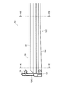
次に、本発明の第2実施形態の冷蔵庫について、図10~図13を用いて説明する。図10は冷蔵庫の左上扉の背面側から見た左上角部を示す部分背面図、図11、図12及び図13はそれぞれ図10に示すパッキンのXI-XI線、XII-XII線及びXIII-XIII線における垂直断面側面図である。なお、この実施形態の基本的な構成は図1~図9を用いて説明した前記第1実施形態と同じであるので、第1実施形態と共通する構成要素には前と同じ符号を付し、図面の記載及びその説明を省略するものとする。
次に、本発明の第2実施形態の冷蔵庫について、図10~図13を用いて説明する。図10は冷蔵庫の左上扉の背面側から見た左上角部を示す部分背面図、図11、図12及び図13はそれぞれ図10に示すパッキンのXI-XI線、XII-XII線及びXIII-XIII線における垂直断面側面図である。なお、この実施形態の基本的な構成は図1~図9を用いて説明した前記第1実施形態と同じであるので、第1実施形態と共通する構成要素には前と同じ符号を付し、図面の記載及びその説明を省略するものとする。
第2実施形態の冷蔵庫1は、パッキン10の上辺部10Tと左上扉5Lとの係合部40として、図10~図13に示す係合溝42と、図11~図13に示す係止片41とを備える。なお、図10は左上扉5Lの右上扉5Rに対向する上側の角部に対応する部分、すなわち前述のパッキン10の角部12に対応する部分を描画している。
係止片41はパッキン10の左上扉5Lに対する取り付け面10aに設けられ、左上扉5L側(図11~図13の左方)に向かって突出するとともに開口部3aの周縁に沿って延びる断面矢尻形状をなす。係止片41は左上扉5L側に向かって突出する方向の先端と根本との略中間部に係合突起43を備える。係合突起43は取り付け面10aに沿う方向に関して係止片41先端の矢尻部分より短い長さで係止片41の周面に対して外側に向かって、すなわち取り付け面10aに沿って外側(図11~図13の上下方向)に向かって突出する。
これにより、係止片41は係合突起43より先端側に、その先端の矢尻部分と係合突起43との間で凹部として形成された第1係止部44を備える。さらに、係止片41は係合突起43より根本側に、その根元と係合突起43との間で凹部として形成された第2係止部45を備える。
係合溝42は左上扉5Lの、パッキン10の係止片41に対応する箇所に設けられ、開口部3aの周縁に沿ってパッキン10が延びる方向に対応して、すなわちパッキン10の角部12から角部11(図5参照、図10の左右方向)に向かって略直線状に延びている。係合溝42は図11に示す角部12に近接した領域の断面形状42a(第1断面形状)と、図13に示す角部12と角部11との中間領域の断面形状42c(第3断面形状)とがほぼ同じ形状をなす。断面形状42a、42cは開口縁部42wの溝幅が係止片41の先端及び係合突起43の幅より狭く、係止片41を係止してパッキン10をしっかりと保持する形状をなす。
そして、係合溝42は自身が延びる方向に関してそれらの間の領域の断面形状42b(第2断面形状、図12参照)が断面形状42a、42cと異なる。断面形状42bは開口縁部42wの溝幅が断面形状42a、42cと比較して広く、係止片41の係合突起43が干渉し難い形状となっている。
上記のように、係合溝42は角部12から角部11に向かって離れるに連れてその断面形状が断面形状42a、断面形状42b、断面形状42cと変化する。なお、係合溝42の、断面形状42aの領域と断面形状42bの領域との間の領域、及び断面形状42bの領域と断面形状42cの領域との間の領域では断面形状がなだらかに変化する。
このような構造の係合部40に対して、パッキン10を左上扉5Lに取り付ける際、係合溝42の断面形状42aを有する角部12に近接した領域では、パッキン10の係止片41の第1係止部44を、角部12が角部12と角部11との中間部分と比較して左上扉5Lから離れる形態となる係合溝42に係止させる。また、係合溝42の断面形状42cを有する角部12と角部11との中間領域では、パッキン10の係止片41の第2係止部45を係合溝42に係止させる。係合溝42の断面形状42bを有する領域では、係合溝42の開口縁部42wが係止片41の係合突起43に干渉し難いので、パッキン10が緩やかに傾斜して延びる。
このようにして、パッキン10の上辺部10Tは開口部3aの周縁に対する接触面10cが角部11に対して角部12に接近するに連れて左上扉5Lから離れる方向に突出するように緩やかに傾斜して延びる。
<第3実施形態>
次に、本発明の第3実施形態の冷蔵庫について、図14~図18を用いて説明する。図14は冷蔵庫の左上扉の背面側から見た左上角部を示す部分背面図、図15及び図16はそれぞれ図14に示すパッキンのXV-XV線及びXVI-XVI線における垂直断面側面図である。図17及び図18は冷蔵庫の左右の上扉の対向部分を示す部分拡大上面図にして、それぞれ左上扉を1°及び5°開放した状態を示すものである。なお、この実施形態の基本的な構成は図1~図9を用いて説明した前記第1実施形態と同じであるので、第1実施形態と共通する構成要素には前と同じ符号を付し、図面の記載及びその説明を省略するものとする。
次に、本発明の第3実施形態の冷蔵庫について、図14~図18を用いて説明する。図14は冷蔵庫の左上扉の背面側から見た左上角部を示す部分背面図、図15及び図16はそれぞれ図14に示すパッキンのXV-XV線及びXVI-XVI線における垂直断面側面図である。図17及び図18は冷蔵庫の左右の上扉の対向部分を示す部分拡大上面図にして、それぞれ左上扉を1°及び5°開放した状態を示すものである。なお、この実施形態の基本的な構成は図1~図9を用いて説明した前記第1実施形態と同じであるので、第1実施形態と共通する構成要素には前と同じ符号を付し、図面の記載及びその説明を省略するものとする。
第3実施形態の冷蔵庫1は、パッキン10の上辺部10Tと左上扉5Lとの係合部50として、図14~図16に示す係合溝52と、図15及び図16に示す係止片51とを備える。なお、図14は左上扉5Lの右上扉5Rに対向する上側の角部に対応する部分、すなわち前述のパッキン10の角部12に対応する部分を描画している。
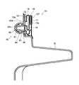
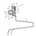
係止片51はパッキン10の左上扉5Lに対する取り付け面10aに設けられ、左上扉5L側(図15及び図16の左方)に向かって突出するとともに開口部3aの周縁に沿って延びる断面矢尻形状をなす。係止片51はその先端の矢尻部分と根元との間で凹部として形成された係止部54を備える。
係合溝52は図15に示す角部12に近接した領域の断面形状52a(第4断面形状)と、図16に示す角部12と角部11との中間領域の断面形状52b(第5断面形状)とが異なる形状をなす。係合溝52の断面形状52bは、図16に示すように係止片51の係止部54を係止してパッキン10をしっかりと保持する形状をなす。
一方、係合溝52の断面形状52aは、図15に示すように開口縁部52wの溝幅が断面形状52bと比較して広く、係止片51の先端の矢尻部分が引っ掛からない形状となっている。すなわち、断面形状52aはパッキン10の角部12を局部的に左上扉5Lから離れる方向または近づく方向に移動可能にする形状をなす。これにより、角部12に近接した領域において、パッキン10は係合部50に係止されない。
上記のように、係合溝52は角部12から角部11に向かって離れるに連れてその断面形状が断面形状52a、断面形状52bと変化する。なお、係合溝52の、断面形状52aの領域と断面形状52bの領域との間の領域では断面形状がなだらかに変化する。
このような構造の係合部50を用いてパッキン10を左上扉5Lに取り付け、左上扉5Lを開口部3aに対して閉鎖すると、パッキン10はその角部12の部分、及び角部12と角部11との中間部分ともに、左上扉5Lと本体筐体2との間に挟まれてピッタリと密着する(図4参照)。パッキン10の左上扉5Lから開口部3a(本体筐体2)に向かう方向の厚みは全体的に均一をなす。
続いて、左上扉5Lを閉鎖状態から開放するとき、開放過程おいてパッキン10はその角部12の部分が、着磁体17の磁力により開口部3a側に引っ張られる。パッキン10は係合溝52の、断面形状52aの領域と断面形状52bの領域との間の領域において、角部12から角部11に向かって離れるに連れて徐々に係止部54による係止度合いが高まる。これにより、パッキン10はその角部12の部分が、角部12と角部11との中間部分と比較して局部的に左上扉5Lから離れる方向に移動して図15、図17及び図18に示す形態となる。なお、図17及び図18には従来例の参考として、パッキン10の角部12の部分が局部的に左上扉5Lから離れる方向に移動しない場合の接触面10cの位置を二点鎖線で描画している。
このようにして、左上扉5Lの開放時において、パッキン10の上辺部10Tは開口部3aの周縁に対する接触面10cが角部11に対して角部12に接近するに連れて左上扉5Lから離れる方向に突出するように緩やかに傾斜して延びる。
<第4実施形態>
次に、本発明の第4実施形態の冷蔵庫について、図19~図23を用いて説明する。図19は冷蔵庫の扉開閉機構のカム機構の一部を示す正面断面図である。図20~図23は扉開閉機構のカム機構の動作を示す平面図である。なお、この実施形態の基本的な構成は図1~図9を用いて説明した前記第1実施形態と同じであるので、第1実施形態と共通する構成要素には前と同じ符号を付し、図面の記載及びその説明を省略するものとする。
次に、本発明の第4実施形態の冷蔵庫について、図19~図23を用いて説明する。図19は冷蔵庫の扉開閉機構のカム機構の一部を示す正面断面図である。図20~図23は扉開閉機構のカム機構の動作を示す平面図である。なお、この実施形態の基本的な構成は図1~図9を用いて説明した前記第1実施形態と同じであるので、第1実施形態と共通する構成要素には前と同じ符号を付し、図面の記載及びその説明を省略するものとする。
第4実施形態の冷蔵庫1は、上扉5及び下扉6各々を回動可能にする扉開閉機構に、図19~図23に示すカム機構を備える。カム機構は左上扉5L、右上扉5R、左下扉6L及び右下扉6R各々の上部及び下部に同様の構造で設けられる。なおここでは、左上扉5Lの下部に設けられたカム機構を例に掲げて説明する。
カム機構は、左上扉5Lと本体筐体2とに設けられた部材からなる。図19は、左上扉5Lの下部に配置されるカム機構の一部、すなわち左上扉5Lの下部の軸側に対応する箇所に配置される部材群を示す正面断面図である。左上扉5Lには軸側に配置されるスライドカム部材60と、開放側に配置されるガイドカム81(図20参照)とが取り付けられる。本体筐体2にはスライドカム部材60と係合するロックカム組品70と、ガイドカム81と係合するガイドピン82(図20参照)とが取り付けられる。
スライドカム部材60は樹脂成形品からなり、上面に上方に向かって突出するボス60a、60bが形成され、上下方向に貫通するネジ孔60c、60dが形成される。ボス60a、60bを左上扉5Lの下面に設けられたボス孔(不図示)に嵌合し、ネジ孔60c、60dに下方からタッピングネジ(不図示)を挿通してスライドカム部材60が左上扉5Lの下面に取り付けられる。また、スライドカム部材60には後述するロック部材61を位置決めするボス孔60fが形成される。
ロックカム組品70はロックカム部材71とアングル72とがネジ73により一体化され、スライドカム部材60と係合してカム機構の一部を構成する。ロックカム部材71は樹脂成形品からなり、アングル72は左上扉5Lの重量を支えるため金属部材からなる。
アングル72には3箇所にネジ孔72aが形成される。ネジ孔72aにタッピングネジを挿通してアングル72、すなわちロックカム組品70が本体筐体2に取り付けられる。また、例えばステンレス鋼等の金属から成るヒンジピン74、ロックピン75及び補助ガイドピン76がそれぞれかしめてアングル72に一体化されている。ヒンジピン74、ロックピン75及び補助ガイドピン76はロックカム部材71をそれぞれ貫通して上方に向かって突出する。
ヒンジピン74の底部には台座部74aが同心に形成される。スライドカム部材60に形成されるボス62の底面62aは左上扉5Lの閉鎖時に台座部74aの上に乗る。ボス62には底面62aに対して下方に突出する段差部62bが形成される。段差部62bの内周側は台座部74aに沿って形成され、台座部74aの周部に接して面取りされる。
図20はカム機構の平面図であって左上扉5Lを閉鎖した状態を示しており、本体筐体2側に取り付けられる部材には斜線を付している。スライドカム部材60には、ロック部材61が取り付けられる。ロック部材61は樹脂成形品からなり、上面に上方に向かって突出するボス(不図示)を備える。ロック部材61はこのボスをスライドカム部材60の下面に設けられたボス孔60f(図19参照)に嵌合させて、タッピングネジ(不図示)等により取り付けられる。
ロック部材61の一端にはアーム部61aが形成される。アーム部61aは延びた方向に略垂直な方向(図20の紙面と略平行をなす方向)の荷重に対して弾性変形するようになっている。アーム部61aの端部にはロックピン75と係合する係合部61bが設けられる。ロック部材61の他端にはロックカム部材71(図19参照)に形成されたストッパー71aに当接して左上扉5Lの回動を規制する規制部61cが設けられる。
スライドカム部材60の一端の下面には長孔状のヒンジ溝63が上方に向かって窪んだ凹部として形成される。ヒンジ溝63の周囲には後述する第2係止位置のときのヒンジピン74を中心とした円筒面62cを有するボス62が形成される。
ロックカム部材71のヒンジピン74の周囲にはヒンジピン74と同心の円筒状の凹面77aを有するリブ77が上方に向かって突出する形で設けられる。スライドカム部材60のヒンジ溝63よりも開口部3aの中央側の下面にはL字型に屈曲した補助ガイド溝64が上方に向かって窪んだ凹部として形成される。補助ガイド溝64は後述する第1係止位置から第2係止位置まで補助ガイドピン76を相対的に案内する案内部64aと、第2係止位置で補助ガイドピン76を相対的に逃がす逃げ部64bとを有する。
左上扉5Lの開放側に取り付けられるガイドカム81は樹脂成形品からなり、屈曲したガイド溝83を備える。本体筐体2にはガイド溝83に係合する例えばステンレス製のガイドピン82がアングル(不図示)に支持されて取り付けられる。
ガイド溝83は後述する第1係止位置から第2係止位置までガイドピン82を相対的に案内する案内部83aと、第2係止位置でガイドピン82を相対的に逃がす逃げ部83bと、案内部83aの端部から第1係止位置のヒンジピン74を中心とする円周方向に延設される円弧部83cとを有する。
続いて、図20~図23を参照して、左上扉5Lの下部のカム機構の動作を説明する。他のカム機構についても同様の動作が行われる。なお、これらの図においてカム機構の各部位は本来破線で表すべきであるが、便宜上実線で示している。また、斜線部分は前述したように本体筐体2側に配置される部材を示している。
前述したように、図20は左上扉5Lを閉鎖した状態を示している。左上扉5Lの閉鎖状態ではヒンジ溝63の一端にヒンジピン74が係止され、カム機構は第1係止位置をとる。第1係止位置では、ガイドピン82がガイド溝83の案内部83aの端部に配置されている。また、補助ガイドピン76が補助ガイド溝64の案内部64aの端部に配置されている。
ガイド溝83の円弧部83cは第1係止位置のヒンジピン74を中心とする円弧上に形成されているので、第1係止位置でヒンジピン74を回動軸として左上扉5Lは閉じる方向に回動することができる。したがって、第1係止位置の左上扉5Lを確実に閉じることができる。このとき、補助ガイド溝64の案内部64aと補助ガイドピン76とが当接して左上扉5Lの回動を規制しないように、第1係止位置のときに補助ガイドピン76と案内部64aとの間には溝の長手方向及び幅方向の隙間A1、A2が設けられている。
ロックピン75はロック部材61の係合部61bと係合し、アーム部61aの弾性力により左上扉5Lが右上扉5Rの方向に付勢されている。これにより、左上扉5Lと右上扉5Rとの間の所定量の隙間を確実に保持するとともに、ヒンジピン74とヒンジ溝63との間の嵌合のための隙間による左上扉5Lの遊動を防止する。したがって、カム機構が第1係止位置の状態を保持するとともに左上扉5Lの開口部3aに対する閉鎖密閉状態をより確実にしている。
外側から左上扉5Lを引くことにより左上扉5Lが開き始めると、左上扉5Lは開放に伴って回動するが、ガイド溝83の案内部83aがガイドピン82と係合するため、第1係止位置のままではヒンジピン74を軸として回動することができない。このため、ヒンジピン74が相対的にヒンジ溝63に案内されるとともにガイドピン82が案内部83aに案内される。また、補助ガイド溝64の案内部64aに設けられた隙間A2により補助ガイドピン76の相対移動が規制されないようになっている。
これにより、左上扉5Lは回動しながら右上扉5Rから離れる方向(図20の左方向)へスライド移動する。したがって、左上扉5Lに設けられたパッキン10は右上扉5Rに設けられたパッキン20から離れる。その結果、パッキン10、20の摺動を回避して損傷が防止されるとともに、摺動摩擦の低減によって開放の操作力が軽減される。
このとき、ボス62の段差部62b(図19参照)が台座部74a(図19参照)に乗り上げて左上扉5Lが持ち上げられる。したがって、左上扉5Lを引く操作力が働いた場合にのみ左上扉5Lを開くことができ、パッキン10の弾性力によって容易に左上扉5Lが閉鎖状態から開いてしまわないようになっている。
また、ロック部材61のアーム部61aが弾性変形し、ロックピン75と係合部61bとの係合解除が開始される。このときに左上扉5Lを持つ手を離すと、左上扉5Lはアーム部61aの弾性力により図20の状態に戻る。したがって、ロック部材61とロックピン75により自閉機能を有し、左上扉5Lを確実に閉じることができるようになっている。
左上扉5Lが回動しながらスライド移動していくと、図21に示すようにヒンジピン74がヒンジ溝63の他端に係止され、カム機構は第2係止位置をとる。また、ボス62の円筒面62cがリブ77の凹面77aに沿って摺動を開始する。
このとき、ガイドピン82及び補助ガイドピン76はそれぞれガイド溝83及び補助ガイド溝64の案内部83a、64aと逃げ部83b、64bとの交差位置に配置される。ガイド溝83及び補助ガイド溝64の逃げ部83b、64bは第2係止位置でのヒンジピン74を中心とする円弧状に形成され、ガイドピン82及び補助ガイドピン76を相対的に逃がすとともに左上扉5Lの回動を案内し、第2係止位置を確実に保持するようになっている。
さらに左上扉5Lを開くと、図22に示すように、ボス62の円筒面62cがリブ77の凹面77aの2箇所で摺動し、ボス62がヒンジ溝63の長手方向に移動できなくなる。これにより、カム機構は第2係止位置の状態を保持し、左上扉5Lが枢支される。リブ77の凹面77aはボス62を案内できればよいので、リブ77に替えて例えばヒンジピン74と同心の円弧上に配列された複数のピン等によって形成しても良い。
また、ガイド溝83がガイドピン82を相対的に案内してカム機構が第2係止位置を保持しながら左上扉5Lが回動する。補助ガイド溝64の案内部64aには補助ガイドピン76との間に隙間A1、A2(図20参照)が設けられているため、ガイド溝83の逃げ部83bとガイドピン82との係合よりも後に補助ガイド溝64の逃げ部64bと補助ガイドピン76との係合が開始される。
さらに左上扉5Lを開くと、図23に示すように、ガイド溝83とガイドピン82との係合が解除される。その後、カム機構は補助ガイド溝64が補助ガイドピン76を相対的に案内して第2係止位置を保持し、左上扉5Lが回動する。また、ロックピン75とロック部材61との係合が解除される。
ここで、ガイドカム81や補助ガイドピン76の取り付け誤差やガイドカムの寸法誤差により、ガイドピン82と補助ガイドピン76との距離と、対応する位置の逃げ部83b、64b間の距離とが一致しない場合がある。このとき、ガイド溝83とガイドピン82との係合と、補助ガイド溝64と補助ガイドピン76との係合とが同時に生じている期間は、該誤差により例えばガイド溝83とガイドピン82との摺動摩擦が大きくなってスムーズに左上扉5Lを開くことができなくなる。
このため、逃げ部83bとガイドピン82とが係合している期間は、逃げ部64bと補助ガイドピン76との隙間を大きくし、逃げ部83bとガイドピン82との係合が解除された後の期間は逃げ部64bと補助ガイドピン76との隙間を小さくしている。逃げ部64bと補助ガイドピン76の隙間を可変して取り付け誤差の影響を回避することによって、左上扉5Lをスムーズに回動させることができる。
なお、逃げ部64bと補助ガイドピン76の係合が開始される前の逃げ部83bとガイドピン82との隙間を小さくし、逃げ部64bと補助ガイドピン76の係合が開始された後の逃げ部83bとガイドピン82との隙間を大きくしても同様の効果を得ることができる。
そして、さらに左上扉5Lが開放されるとロック部材61の規制部61cがロックカム部材71(図19参照)に形成されたストッパー71aと当接し、左上扉5Lの回動の範囲が規制される。また、以上に説明した図20~図23に示す動作と逆の動作により左上扉5Lを閉じることができる。
本実施形態において左上扉5Lを閉じる場合、カム機構が第2係止位置から第1係止位置に移行するときに、左上扉5Lは回動しながら右上扉5Rに近づく方向(図20の右方向)へスライド移動する。したがって、左上扉5Lに設けられたパッキン10は右上扉5Rに設けられたパッキン20に押し付けられるように接触する。この構成により、左上扉5Lと右上扉5Rとが互いに対向し合う部分に対応する箇所に冷蔵室3が仕切り部を備えていなくても、その対向し合う部分が密閉されて外部への冷気漏れを防止することができる。
また、本実施形態は、左上扉5Lに対するパッキン10の取り付けに関して、第3実施形態として説明した構造を有する(図14~図18参照)。すなわち、左上扉5Lの開放過程において、パッキン10はその角部12の部分が、角部12と角部11との中間部分と比較して局部的に左上扉5Lから離れる方向に移動して図15、図17及び図18に示す形態となる。
ここで、図17及び図18に参考例として二点鎖線で描画した従来例のようにパッキン10の角部12の部分が局部的に左上扉5Lから離れる方向に移動しない場合、左上扉5Lと右上扉5Rとの密着度合いが比較的高いと、左上扉5Lを開放するときに左上扉5Lに釣られて右上扉5Rも開いてしまう虞がある。これにより、冷蔵室3の外部への冷気の流出量が増加し、冷蔵庫1の省エネルギー化が阻害される可能性がある。
そこで、本実施形態によれば、パッキン10の角部12の部分が、角部12と角部11との中間部分と比較して局部的に左上扉5Lから離れる方向に移動するので(図15、図17及び図18参照)、左上扉5Lを開放するとき、左上扉5Lと右上扉5Rとの間の接触圧力が低減されて左上扉5Lに釣られて右上扉5Rも開いてしまうことを抑制することが可能である。
これらの実施形態のように、冷蔵庫1のパッキン10の上辺部10Tは、左上扉5Lの開放時において、左上扉5Lの角部に対応する角部12の部分の開口部3aの周縁に対する接触面10cが角部12と他の角部である角部11との中間部分と比較して左上扉5Lから離れる方向に突出する。これにより、左上扉5Lの開放時において、パッキン10の角部12の左上扉5Lから冷蔵室3の開口部3aに向かう方向の厚みが増加する。さらに、左上扉5Lの閉鎖時において、パッキン10の角部12の開口部3aとの接触圧力が増加する。したがって、左上扉5Lの角部においてパッキン10と冷蔵室3の開口部3aとの間に隙間ができることを抑制することが可能である。
また、第1実施形態で説明したパッキン10は、左上扉5Lから離れる方向または近づく方向に伸縮可能な中空部14を備え、左上扉5Lの角部に対応する角部12の部分の中空部14が、角部12と他の角部11との中間部分と比較して左上扉5Lから離れる方向に伸びた状態にして角部12の部分が形成されることにより、左上扉5Lの開放時において、左上扉5Lの角部に対応する角部12の部分が角部12と他の角部である角部11との中間部分と比較して左上扉5Lから離れる方向に突出する。これにより、パッキン10の中空部14の構造を利用することで、左上扉5Lの開放時におけるパッキン10の角部12の厚みが増加し、左上扉5Lの閉鎖時におけるパッキン10の角部12の接触圧力が増加する。したがって、左上扉5Lの角部においてパッキン10と冷蔵室3の開口部3aとの間に隙間ができることを抑制することが可能である。
そして、第2実施形態で説明した冷蔵庫1は、パッキン10の左上扉5Lに対する取り付け箇所に設けられパッキン10を左上扉5Lから離れる方向または近づく方向の複数箇所で左上扉5Lに対して係止可能にする第1係止部44及び第2係止部45を備え、パッキン10の、左上扉5Lの角部に対応する角部12の部分が、角部12と他の角部である角部11との中間部分と比較して左上扉5Lから離れる形態となる第1係止部44に係止されることにより、左上扉5Lの開放時において、左上扉5Lの角部に対応する角部12の部分が角部12と他の角部である角部11との中間部分と比較して左上扉5Lから離れる方向に突出する。
より詳しく言えば、冷蔵庫1は、パッキン10の取り付け面10aに設けられ左上扉5Lに向かって突出する断面矢尻形状をなす係止片41と、係止片41の先端と根本との略中間部に設けられた係止片41の周面に対して外側に向かって延びる係合突起43と、係止片41の先端の矢尻部分と係合突起43との間で凹部として形成された第1係止部44と、係止片41の根元と係合突起43との間で凹部として形成された第2係止部45と、係止片41を係止してパッキン10を保持するとともに角部12から他の角部である角部11に向かって離れるに連れてその断面形状が断面形状42a、断面形状42b、断面形状42cと変化する係合溝42と、を備える。そして、係合溝42は、断面形状42aの領域で係止片41の第1係止部44を係止し、断面形状42cの領域で係止片41の第2係止部45を係止する。
これにより、パッキン10の左上扉5Lに対する取り付け構造を利用することで、左上扉5Lの開放時におけるパッキン10の角部12の厚みが増加し、左上扉5Lの閉鎖時におけるパッキン10の角部12の接触圧力が増加する。したがって、左上扉5Lの角部においてパッキン10と冷蔵室3の開口部3aとの間に隙間ができることを抑制することが可能である。
さらに、第3実施形態で説明した冷蔵庫1は、パッキン10の左上扉5Lに対する取り付け箇所に設けられパッキン10の左上扉5Lの角部に対応する角部12の部分を局部的に左上扉5Lから離れる方向または近づく方向に移動可能にして係合する係合部50を備え、左上扉5Lの閉鎖状態からの開放過程おいてパッキン10を左上扉5Lから離隔するとき、パッキン10の、左上扉5Lの角部に対応する角部12の部分が、角部12と他の角部である角部11との中間部分と比較して局部的に左上扉5Lから離れる方向に移動することにより、左上扉5Lの開放時において、左上扉5Lの角部に対応する角部12の部分が角部12と他の角部である角部11との中間部分と比較して左上扉5Lから離れる方向に突出する。
より詳しく言えば、冷蔵庫1は、係合部50が、パッキン10の取り付け面10aに設けられ左上扉5Lに向かって突出する断面矢尻形状をなす係止片51と、係止片51の先端の矢尻部分と根元との間で凹部として形成された係止部54と、係止片51を係止してパッキン10を保持するとともに角部12から角部11に向かって離れるに連れてその断面形状が断面形状52a、断面形状52bと変化する係合溝52と、を備える。そして、係合溝52は、断面形状52aが係止片51の先端の矢尻部分が引っ掛からない形状をなし、断面形状52bの領域で係止片51の係止部54を係止する。
これにより、左上扉5Lの開放時にパッキン10の角部12が変位するというパッキン10の構造を利用することで、左上扉5Lの開放時におけるパッキン10の角部12の厚みが増加し、左上扉5Lの閉鎖時におけるパッキン10の角部12の接触圧力が増加する。したがって、左上扉5Lの角部においてパッキン10と冷蔵室3の開口部3aとの間に隙間ができることを抑制することが可能である。
そして、本発明の上記実施形態の構成によれば、冷蔵室3の前方の開口部3aを確実に密閉することができ、冷却効率を向上させることが可能な冷蔵庫1を提供することができる。
以上、本発明の実施形態につき説明したが、本発明の範囲はこれに限定されるものではなく、発明の主旨を逸脱しない範囲で種々の変更を加えて実施することができる。
例えば、上記実施形態では、左上扉5Lの右上扉5Rに対向する上側の角部に対応する部分である、パッキン10の上辺部10Tの角部12の部分を一例として掲げて説明したが、本発明の適用対象は当該箇所に限定されるわけではなく、他の箇所であっても良い。本発明の適用対象は上辺部10Tの角部11であっても良いし、下辺部10B、外辺部10Sまたは対向部10Kの他の角部であっても良い。そして、本発明の適用対象は4箇所の角部のうち1箇所のみへの適用に限定されるわけではなく、複数、例えば4箇所すべてに適用しても良い。さらに、本発明を下扉6に対して適用しても良い。
また、本実施形態では、観音開き式の扉を例として掲げて説明したが、片開き式の扉に対して本発明を適用しても良い。さらに、扉の開閉方向は限定せず、左右方向、上下方向いずれの方向に開閉するタイプの扉にも本発明を適用することができる。
本発明は冷蔵庫において利用可能である。
1 冷蔵庫
2 本体筐体
3 冷蔵室(貯蔵室)
3a 開口部
5 上扉(扉)
5L 左上扉(扉)
5R 右上扉(扉)
10、20 パッキン
10a 取り付け面
10c 接触面
10T 上辺部
10K 対向部
11、12 角部
14 中空部
16 着磁体保持部
17 着磁体
30、40、50 係合部
31、41、51 係止片
32、42、52 係合溝
42a 断面形状(第1断面形状)
42b 断面形状(第2断面形状)
42c 断面形状(第3断面形状)
43 係合突起
44 第1係止部(係止部)
45 第2係止部(係止部)
52a 断面形状(第4断面形状)
52b 断面形状(第5断面形状)
54 係止部
2 本体筐体
3 冷蔵室(貯蔵室)
3a 開口部
5 上扉(扉)
5L 左上扉(扉)
5R 右上扉(扉)
10、20 パッキン
10a 取り付け面
10c 接触面
10T 上辺部
10K 対向部
11、12 角部
14 中空部
16 着磁体保持部
17 着磁体
30、40、50 係合部
31、41、51 係止片
32、42、52 係合溝
42a 断面形状(第1断面形状)
42b 断面形状(第2断面形状)
42c 断面形状(第3断面形状)
43 係合突起
44 第1係止部(係止部)
45 第2係止部(係止部)
52a 断面形状(第4断面形状)
52b 断面形状(第5断面形状)
54 係止部
Claims (5)
- 開口部を有する貯蔵室と、
前記開口部を開閉する正面視矩形をなす扉と、
前記扉の前記開口部の周縁に対応する部分に取り付けられ前記扉の閉鎖時に前記開口部の周縁に接触するパッキンと、
を備え、
前記パッキンは、前記扉の開放時において、前記扉の角部に対応する部分が前記角部と他の角部との中間部分と比較して前記扉から離れる方向に突出することを特徴とする冷蔵庫。 - 前記パッキンは、前記扉から離れる方向または近づく方向に伸縮可能な中空部を備え、前記扉の前記角部に対応する部分の前記中空部が、前記角部と他の角部との中間部分と比較して前記扉から離れる方向に伸びた状態にして形成されることにより、前記扉の開放時において、前記扉の前記角部に対応する部分が前記角部と他の角部との中間部分と比較して前記扉から離れる方向に突出することを特徴とする請求項1に記載の冷蔵庫。
- 前記パッキンの前記扉に対する取り付け箇所に設けられ前記パッキンを前記扉から離れる方向または近づく方向の複数箇所で前記扉に対して係止可能にする係止部を備え、前記パッキンは、前記扉の前記角部に対応する部分が、前記角部と他の角部との中間部分と比較して前記扉から離れる形態となる前記係止部に係止されることにより、前記扉の開放時において、前記扉の前記角部に対応する部分が前記角部と他の角部との中間部分と比較して前記扉から離れる方向に突出することを特徴とする請求項1に記載の冷蔵庫。
- 前記パッキンの前記扉に対する取り付け箇所に設けられ前記扉に向かって突出する断面矢尻形状をなす係止片と、
前記係止片の先端と根本との略中間部に設けられた前記係止片の周面に対して外側に向かって延びる係合突起と、
前記係止片の先端の前記矢尻の部分と前記係合突起との間で凹部として形成された第1係止部と、
前記係止片の根元と前記係合突起との間で凹部として形成された第2係止部と、
前記係止片を係止して前記パッキンを保持するとともに前記扉の前記角部から他の角部に向かって離れるに連れてその断面形状が第1断面形状、第2断面形状、第3断面形状と変化する係合溝と、
を備え、
前記係合溝は、前記第1断面形状の領域で前記係止片の前記第1係止部を係止し、前記第3断面形状の領域で前記係止片の前記第2係止部を係止することを特徴とする請求項3に記載の冷蔵庫。 - 前記パッキンの前記扉に対する取り付け箇所に設けられ前記パッキンの前記扉の前記角部に対応する部分を局部的に前記扉から離れる方向または近づく方向に移動可能にして係合する係合部を備え、前記パッキンは、前記扉の閉鎖状態からの開放過程おいて前記扉から離隔するとき、前記扉の前記角部に対応する部分が、前記角部と他の角部との中間部分と比較して局部的に前記扉から離れる方向に移動することにより、前記扉の開放時において、前記扉の前記角部に対応する部分が前記角部と他の角部との中間部分と比較して前記扉から離れる方向に突出することを特徴とする請求項1に記載の冷蔵庫。
Applications Claiming Priority (2)
| Application Number | Priority Date | Filing Date | Title |
|---|---|---|---|
| JP2013-228075 | 2013-11-01 | ||
| JP2013228075A JP5770247B2 (ja) | 2013-11-01 | 2013-11-01 | 冷蔵庫 |
Publications (1)
| Publication Number | Publication Date |
|---|---|
| WO2015064189A1 true WO2015064189A1 (ja) | 2015-05-07 |
Family
ID=53003804
Family Applications (1)
| Application Number | Title | Priority Date | Filing Date |
|---|---|---|---|
| PCT/JP2014/072215 Ceased WO2015064189A1 (ja) | 2013-11-01 | 2014-08-26 | 冷蔵庫 |
Country Status (2)
| Country | Link |
|---|---|
| JP (1) | JP5770247B2 (ja) |
| WO (1) | WO2015064189A1 (ja) |
Citations (5)
| Publication number | Priority date | Publication date | Assignee | Title |
|---|---|---|---|---|
| JPS5222854U (ja) * | 1975-08-07 | 1977-02-17 | ||
| JPH0460374A (ja) * | 1990-06-27 | 1992-02-26 | Hitachi Ltd | 冷蔵庫 |
| JP2010060143A (ja) * | 2008-09-01 | 2010-03-18 | Sharp Corp | 扉のシール構造及びこれを備えた冷蔵庫 |
| JP2012037151A (ja) * | 2010-08-09 | 2012-02-23 | Hitachi Appliances Inc | 冷凍機器 |
| JP2012229822A (ja) * | 2011-04-25 | 2012-11-22 | Sharp Corp | 冷蔵庫 |
-
2013
- 2013-11-01 JP JP2013228075A patent/JP5770247B2/ja active Active
-
2014
- 2014-08-26 WO PCT/JP2014/072215 patent/WO2015064189A1/ja not_active Ceased
Patent Citations (5)
| Publication number | Priority date | Publication date | Assignee | Title |
|---|---|---|---|---|
| JPS5222854U (ja) * | 1975-08-07 | 1977-02-17 | ||
| JPH0460374A (ja) * | 1990-06-27 | 1992-02-26 | Hitachi Ltd | 冷蔵庫 |
| JP2010060143A (ja) * | 2008-09-01 | 2010-03-18 | Sharp Corp | 扉のシール構造及びこれを備えた冷蔵庫 |
| JP2012037151A (ja) * | 2010-08-09 | 2012-02-23 | Hitachi Appliances Inc | 冷凍機器 |
| JP2012229822A (ja) * | 2011-04-25 | 2012-11-22 | Sharp Corp | 冷蔵庫 |
Also Published As
| Publication number | Publication date |
|---|---|
| JP5770247B2 (ja) | 2015-08-26 |
| JP2015087084A (ja) | 2015-05-07 |
Similar Documents
| Publication | Publication Date | Title |
|---|---|---|
| JP6952133B2 (ja) | 冷蔵庫 | |
| KR20110032898A (ko) | 냉기 유출방지 부재를 갖는 냉장고 | |
| JP2022546122A (ja) | 扉の開閉を補助可能なビルトイン式冷蔵庫 | |
| JP2015025633A (ja) | 冷却貯蔵庫の扉装置 | |
| JP2010060143A (ja) | 扉のシール構造及びこれを備えた冷蔵庫 | |
| JP5770247B2 (ja) | 冷蔵庫 | |
| JP2002022349A (ja) | 冷蔵庫扉 | |
| JP2013100942A (ja) | 冷蔵庫 | |
| US12018755B2 (en) | Seal structure of cold storage and cold storage | |
| JP6628896B2 (ja) | 冷蔵庫 | |
| JP6360685B2 (ja) | 冷蔵庫 | |
| JP2018119696A (ja) | センターシールの取付構造 | |
| KR100707456B1 (ko) | 냉장고의 도어 개스킷 장치 | |
| CN222335796U (zh) | 一种对开门车载冰箱门的密封结构 | |
| JP2000130920A (ja) | 貯蔵庫 | |
| JP6282445B2 (ja) | 貯蔵庫 | |
| KR100707434B1 (ko) | 냉장고의 사이드 개스킷 분리 장치 | |
| KR100733310B1 (ko) | 냉장고의 도어 개폐 장치 | |
| CN219868679U (zh) | 制冷设备 | |
| JP6561154B2 (ja) | 貯蔵庫 | |
| JP4708235B2 (ja) | 扉開閉機構 | |
| JPH11159946A (ja) | 冷蔵庫 | |
| KR100707462B1 (ko) | 냉장고의 도어 개폐 장치 | |
| JP2022166699A (ja) | 冷蔵庫 | |
| JP2024047790A (ja) | 貯蔵庫 |
Legal Events
| Date | Code | Title | Description |
|---|---|---|---|
| 121 | Ep: the epo has been informed by wipo that ep was designated in this application |
Ref document number: 14859081 Country of ref document: EP Kind code of ref document: A1 |
|
| NENP | Non-entry into the national phase |
Ref country code: DE |
|
| 122 | Ep: pct application non-entry in european phase |
Ref document number: 14859081 Country of ref document: EP Kind code of ref document: A1 |