WO2015060321A1 - Moteur - Google Patents
Moteur Download PDFInfo
- Publication number
- WO2015060321A1 WO2015060321A1 PCT/JP2014/078019 JP2014078019W WO2015060321A1 WO 2015060321 A1 WO2015060321 A1 WO 2015060321A1 JP 2014078019 W JP2014078019 W JP 2014078019W WO 2015060321 A1 WO2015060321 A1 WO 2015060321A1
- Authority
- WO
- WIPO (PCT)
- Prior art keywords
- exhaust
- engine
- supercharger
- exhaust manifold
- valve
- Prior art date
Links
Images


Classifications
-
- F—MECHANICAL ENGINEERING; LIGHTING; HEATING; WEAPONS; BLASTING
- F02—COMBUSTION ENGINES; HOT-GAS OR COMBUSTION-PRODUCT ENGINE PLANTS
- F02B—INTERNAL-COMBUSTION PISTON ENGINES; COMBUSTION ENGINES IN GENERAL
- F02B37/00—Engines characterised by provision of pumps driven at least for part of the time by exhaust
- F02B37/12—Control of the pumps
- F02B37/22—Control of the pumps by varying cross-section of exhaust passages or air passages, e.g. by throttling turbine inlets or outlets or by varying effective number of guide conduits
-
- F—MECHANICAL ENGINEERING; LIGHTING; HEATING; WEAPONS; BLASTING
- F01—MACHINES OR ENGINES IN GENERAL; ENGINE PLANTS IN GENERAL; STEAM ENGINES
- F01N—GAS-FLOW SILENCERS OR EXHAUST APPARATUS FOR MACHINES OR ENGINES IN GENERAL; GAS-FLOW SILENCERS OR EXHAUST APPARATUS FOR INTERNAL COMBUSTION ENGINES
- F01N13/00—Exhaust or silencing apparatus characterised by constructional features ; Exhaust or silencing apparatus, or parts thereof, having pertinent characteristics not provided for in, or of interest apart from, groups F01N1/00 - F01N5/00, F01N9/00, F01N11/00
- F01N13/08—Other arrangements or adaptations of exhaust conduits
- F01N13/10—Other arrangements or adaptations of exhaust conduits of exhaust manifolds
- F01N13/107—More than one exhaust manifold or exhaust collector
-
- F—MECHANICAL ENGINEERING; LIGHTING; HEATING; WEAPONS; BLASTING
- F02—COMBUSTION ENGINES; HOT-GAS OR COMBUSTION-PRODUCT ENGINE PLANTS
- F02B—INTERNAL-COMBUSTION PISTON ENGINES; COMBUSTION ENGINES IN GENERAL
- F02B37/00—Engines characterised by provision of pumps driven at least for part of the time by exhaust
- F02B37/004—Engines characterised by provision of pumps driven at least for part of the time by exhaust with exhaust drives arranged in series
-
- F—MECHANICAL ENGINEERING; LIGHTING; HEATING; WEAPONS; BLASTING
- F02—COMBUSTION ENGINES; HOT-GAS OR COMBUSTION-PRODUCT ENGINE PLANTS
- F02B—INTERNAL-COMBUSTION PISTON ENGINES; COMBUSTION ENGINES IN GENERAL
- F02B37/00—Engines characterised by provision of pumps driven at least for part of the time by exhaust
- F02B37/013—Engines characterised by provision of pumps driven at least for part of the time by exhaust with exhaust-driven pumps arranged in series
-
- F—MECHANICAL ENGINEERING; LIGHTING; HEATING; WEAPONS; BLASTING
- F02—COMBUSTION ENGINES; HOT-GAS OR COMBUSTION-PRODUCT ENGINE PLANTS
- F02B—INTERNAL-COMBUSTION PISTON ENGINES; COMBUSTION ENGINES IN GENERAL
- F02B37/00—Engines characterised by provision of pumps driven at least for part of the time by exhaust
- F02B37/02—Gas passages between engine outlet and pump drive, e.g. reservoirs
- F02B37/025—Multiple scrolls or multiple gas passages guiding the gas to the pump drive
-
- F—MECHANICAL ENGINEERING; LIGHTING; HEATING; WEAPONS; BLASTING
- F01—MACHINES OR ENGINES IN GENERAL; ENGINE PLANTS IN GENERAL; STEAM ENGINES
- F01N—GAS-FLOW SILENCERS OR EXHAUST APPARATUS FOR MACHINES OR ENGINES IN GENERAL; GAS-FLOW SILENCERS OR EXHAUST APPARATUS FOR INTERNAL COMBUSTION ENGINES
- F01N2240/00—Combination or association of two or more different exhaust treating devices, or of at least one such device with an auxiliary device, not covered by indexing codes F01N2230/00 or F01N2250/00, one of the devices being
- F01N2240/36—Combination or association of two or more different exhaust treating devices, or of at least one such device with an auxiliary device, not covered by indexing codes F01N2230/00 or F01N2250/00, one of the devices being an exhaust flap
-
- F—MECHANICAL ENGINEERING; LIGHTING; HEATING; WEAPONS; BLASTING
- F01—MACHINES OR ENGINES IN GENERAL; ENGINE PLANTS IN GENERAL; STEAM ENGINES
- F01N—GAS-FLOW SILENCERS OR EXHAUST APPARATUS FOR MACHINES OR ENGINES IN GENERAL; GAS-FLOW SILENCERS OR EXHAUST APPARATUS FOR INTERNAL COMBUSTION ENGINES
- F01N2590/00—Exhaust or silencing apparatus adapted to particular use, e.g. for military applications, airplanes, submarines
- F01N2590/02—Exhaust or silencing apparatus adapted to particular use, e.g. for military applications, airplanes, submarines for marine vessels or naval applications
-
- Y—GENERAL TAGGING OF NEW TECHNOLOGICAL DEVELOPMENTS; GENERAL TAGGING OF CROSS-SECTIONAL TECHNOLOGIES SPANNING OVER SEVERAL SECTIONS OF THE IPC; TECHNICAL SUBJECTS COVERED BY FORMER USPC CROSS-REFERENCE ART COLLECTIONS [XRACs] AND DIGESTS
- Y02—TECHNOLOGIES OR APPLICATIONS FOR MITIGATION OR ADAPTATION AGAINST CLIMATE CHANGE
- Y02T—CLIMATE CHANGE MITIGATION TECHNOLOGIES RELATED TO TRANSPORTATION
- Y02T10/00—Road transport of goods or passengers
- Y02T10/10—Internal combustion engine [ICE] based vehicles
- Y02T10/12—Improving ICE efficiencies
Definitions
- the present invention relates to an engine. Specifically, it relates to a turbocharged engine.
- an engine in which each exhaust manifold is communicated via an on-off valve is known.
- This engine is configured so that a dynamic pressure supercharging exhaust manifold can be changed to a static pressure exhaust manifold by opening an on-off valve.
- the engine can suppress deterioration in fuel consumption due to heat loss by communicating the exhaust manifolds and increasing the actual pipe diameter. For example, as described in Patent Document 1.
- Patent Document 1 requires a communication pipe and an on-off valve for communicating each exhaust manifold in order to switch a dynamic pressure supercharging exhaust manifold to a static pressure supercharging exhaust manifold.
- the communication pipe and the on-off valve that allow switching between the dynamic pressure supercharging method and the static pressure supercharging method are excessive facilities. It was a disadvantage that increased costs.
- the present invention has been made in view of the above circumstances, and an exhaust manifold that can be switched between a dynamic pressure supercharging method and a static pressure supercharging method can be easily obtained without replacing the exhaust manifold itself. It is an object of the present invention to provide an engine that can be changed to an exhaust manifold of only a system or a static pressure supercharging system.
- a plurality of independent exhaust manifolds are respectively connected to the supercharger, and each exhaust manifold is connected to each other by a connecting pipe, and each exhaust manifold is independently connected to the connecting pipe.
- the open / close valve is provided, and the connecting pipe is configured to be detachable from each exhaust manifold for each part including the open / close valve or for each open / close valve.
- three or more independent exhaust manifolds are provided, and a first reference value and a second reference value for the engine load factor are set for each engine speed, and the load factor is the first. If it is less than the reference value, all the on-off valves are closed, and if the load factor is equal to or greater than the first reference value and less than the second place reference, some on-off valves are opened and the load factor is If it is above the reference value, all the on-off valves are opened.
- the on-off valves when the increase / decrease amount per unit time of the load factor is equal to or greater than a predetermined value, all the on-off valves are closed, and the increase / decrease amount per unit time of the load factor is less than a predetermined value, When the state continues for a predetermined time, the on-off valve is opened / closed according to the load factor.
- the connecting pipe including the on-off valve or the on-off valve is easily detached from the exhaust manifold.
- an exhaust manifold that can be switched between the dynamic pressure supercharging method and the static pressure supercharging method without changing the exhaust manifold itself can be easily changed to an exhaust manifold of only the dynamic pressure supercharging method or the static pressure supercharging method. Can be changed.
- the connecting pipe is intensively arranged at one end of each exhaust manifold.
- the engine can constitute an exhaust manifold that can be switched between a dynamic pressure supercharging method and a static pressure supercharging method with a configuration that allows easy attachment / detachment of the connecting pipe and maintenance of the on-off valve.
- the pressure state of the exhaust gas supplied to the supercharger is changed based on the engine load factor.
- the responsiveness of the supercharger is improved. Therefore, generation
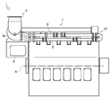
- the perspective view which shows the engine which concerns on 1st embodiment of this invention.
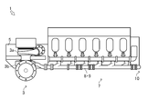
- the side view which shows the engine which concerns on 1st embodiment of this invention.
- the top view which shows the engine which concerns on 1st embodiment of this invention.
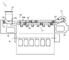
- the perspective view which shows the engine which concerns on 2nd embodiment of this invention The side view which shows the engine which concerns on 2nd embodiment of this invention.
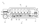
- a ship 100 that is a first embodiment of a ship on which an engine 1 including a supercharger 3 according to the present invention is mounted will be described with reference to FIG.
- the ship 100 includes a hull 101, a bridge 102, an engine room 103, a propeller 104, and a rudder 108.
- the ship 100 is provided with a bridge 102 having a cockpit or the like above the hull 101.
- the ship 100 also has an engine room 103 behind the hull 101.
- the engine room 103 is provided with a main engine 105 that is an internal combustion engine that drives the propeller 104 and an auxiliary machine 106 that is an internal combustion engine that drives the generator 107.
- a propeller 104 and a rudder 108 are provided at the stern of the hull 101.
- the ship 100 is configured such that the power of the main engine 105 can be transmitted to the propeller 104 via the propeller shaft 104a.
- the main engine 105 and the auxiliary machine 106 are composed of the engine 1 which is a diesel engine using light oil or heavy oil as fuel.
- the engine 1 rotates and drives the output shaft by mixing outside air and fuel and burning them.
- the engine 1 is not limited to a diesel engine.
- the engine 1 is a diesel engine, and in the present embodiment, is an in-line six-cylinder engine having six cylinders.
- an in-line six-cylinder engine having a single-stage supercharger is used, but the present invention is not limited to this, and any multi-cylinder engine having at least one supercharger may be used.
- Engine 1 rotates the output shaft by mixing external air and fuel inside each cylinder and burning them.
- the engine 1 includes an intake device 2 that takes in outside air and an exhaust device 7 that discharges exhaust to the outside.
- the intake device 2 includes a compressor unit 3 a of the supercharger 3, an air supply pipe 4, an intercooler 5, and an air supply manifold 6.
- the supercharger 3 pressurizes and compresses the intake air using the exhaust pressure of the exhaust as a drive source.
- the supercharger 3 includes a compressor unit 3a and a turbine unit 3b.
- Compressor section 3a of supercharger 3 compresses and compresses intake air.
- the compressor part 3a is connected with the turbine part 3b by the connecting shaft 3c.
- the compressor unit 3a is configured so that the rotational power from the turbine unit 3b can be transmitted via the connecting shaft 3c.
- An intercooler 5 is connected to the compressor unit 3 a via an air supply pipe 4.
- the intercooler 5 cools the pressurized intake air.
- the intercooler 5 exchanges heat between cooling water supplied by a cooling water pump (not shown) and pressurized intake air (hereinafter, the pressurized intake air compressed and compressed by the compressor unit 3a is referred to as supply air). To cool the supply air.
- the intercooler 5 is connected to an air supply manifold 6.
- the air supply manifold 6 distributes the air supply to the cylinders of the engine 1.
- the air supply manifold 6 is connected to each cylinder of the engine 1.
- the supply manifold 6 is configured to be able to supply supply air cooled by the intercooler 5 to each cylinder of the engine 1.
- the exhaust device 7 includes exhaust manifolds 8 and 9 and a turbine portion 3 b of the supercharger 3.
- the exhaust manifolds 8 and 9 exhaust into two cylinder groups (in the present embodiment, the first, fourth and fifth cylinders, and the second, third and sixth cylinders) composed of cylinders in the same phase of the engine 1.
- Manifolds 8 and 9 are connected independently. That is, the exhaust manifold 8 exhausts exhaust from the first, fourth, and fifth cylinders, and the exhaust manifold 9 exhausts exhaust from the second, third, and sixth cylinders.
- the exhaust manifolds 8 and 9 are detachably connected with connecting pipes 10 (see the shaded portions in FIG. 6) at the end (one side end).
- the exhaust manifolds 8 and 9 are connected to the supercharger 3 at the other end.
- the connecting pipe 10 includes a bent pipe 10a, an on-off valve 10b, and an extension pipe 10c.
- the connecting pipe 10 is configured to be detachable from the exhaust manifolds 8 and 9. By being configured in this way, the connecting pipe 10 is configured so that independent exhaust manifolds 8 and 9 can be connected to each other.
- the exhaust manifolds 8 and 9 are connected to each other at one end by the connecting pipe 10.
- the connecting pipe 10 is arranged at one end of each of the exhaust manifolds 8 and 9, so that the exhaust device 7 has a configuration in which the connecting pipe 10 can be easily attached and detached and the on-off valve 10b can be easily maintained.
- Exhaust manifolds 8 and 9 that can be switched between the method and the static pressure supercharging method can be configured.
- the turbine section 3b of the supercharger 3 generates rotational power by the exhaust pressure.
- the turbine unit 3b is connected to the compressor unit 3a by a connecting shaft 3c, and is configured to be able to transmit rotational power to the compressor unit 3a.
- Exhaust manifolds 8 and 9 are connected to the turbine section 3b.
- the turbine part 3b is connected outside via the purification apparatus etc. which are not shown in figure.
- the intake device 2 the compressor section 3a, the supply pipe 4, the intercooler 5, and the supply manifold 6 of the supercharger 3 are connected in order from the upstream side (external).
- the exhaust device 7 is connected to the exhaust manifolds 8 and 9 from the upstream side (engine 1), the turbine section 3b of the supercharger 3, an exhaust pipe (not shown), and the like in this order.
- the intercooler 5 is fixed to a side surface of one end portion in the axial direction of the output shaft A of the engine 1.
- the supercharger 3 is fixed to the upper part of the intercooler 5. That is, in the engine 1, the supercharger 3 and the intercooler 5 are arranged at one end portion in the axial direction of the output shaft A.
- the air supply manifold 6 is formed on one side of the engine block of the engine 1 in the direction orthogonal to the output shaft A in the horizontal plane.
- the air supply manifold 6 is configured to communicate with an intercooler 5 fixed to a side surface of one end portion of the engine 1.
- the exhaust manifolds 8 and 9 are piped on the other side in a direction orthogonal to the output shaft A of the engine 1 on a horizontal plane.
- the exhaust manifold 9 is piped alongside the exhaust manifold 8 below the exhaust manifold 8.
- the intake air discharged from the supercharger 3 is supplied to the intercooler 5 through the air supply pipe 4.
- the intake air supplied to the intercooler 5 is cooled and then supplied to the engine 1 via the supply manifold 6.
- the exhaust from the engine 1 is supplied to the turbine section 3 b of the supercharger 3 through the exhaust manifold 8 and the exhaust manifold 9.
- the turbine part 3b is rotated by exhaust.
- the rotational power of the turbine part 3b is transmitted to the compressor part 3a via the connecting shaft 3c.
- Exhaust gas supplied to the turbine section 3b is discharged to the outside via a purification device (not shown).
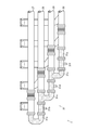
- FIGS. 6 and 7 show one side portions of the exhaust manifolds 8 and 9 of the engine 1.
- a connecting pipe 10 (shaded portion) is detachably connected to the end (one side end) opposite to the supercharger 3 to the exhaust manifolds 8 and 9.
- the exhaust manifolds 8 and 9 are connected to the supercharger 3 at the other end (see FIGS. 2 to 5).
- the connecting pipe 10 connects the exhaust manifold 8 and the exhaust manifold 9.
- the connecting pipe 10 includes a bent pipe 10a, an on-off valve 10b, or an extension pipe 10c.
- the connecting pipe 10 is configured to be detachable at one end portion of the exhaust manifolds 8 and 9.
- the connecting pipe 10 is configured to be able to switch whether the exhaust manifold 8 and the exhaust manifold 9 are communicated with each other depending on the state of the on-off valve 10b.
- the connecting pipe 10 is configured so that an extension pipe 10c can be connected instead of the on-off valve 10b.
- the connecting pipe 10 is configured to be able to connect the exhaust manifold 8 and the exhaust manifold 9 without using the on-off valve 10b.
- the exhaust device 7 when the on-off valve 10 b of the connecting pipe 10 is closed, the exhaust manifold 8 and the exhaust manifold 9 are independently connected to the second turbine portion 3 b of the supercharger 3. That is, the exhaust device 7 includes an exhaust manifold corresponding to the dynamic pressure supercharging method. Further, when the on-off valve 10b is opened, the exhaust device 7 is connected to the turbine section 3b of the supercharger 3 with the exhaust manifold 8 and the exhaust manifold 9 communicating with each other. That is, the exhaust device 7 includes exhaust manifolds 8 and 9 corresponding to the static pressure supercharging system.
- the exhaust pipe 7 is removed from the exhaust manifolds 8 and 9 in the exhaust device 7. At this time, one side end portions of the exhaust manifolds 8 and 9 are sealed by the lids 8a and 9a.
- the exhaust device 7 is connected to the supercharger 3 with the exhaust manifold 8 and the exhaust manifold 9 being independent from each other. That is, the exhaust device 7 includes exhaust manifolds 8 and 9 that are compatible only with the dynamic pressure supercharging method.
- the exhaust device 7 when exhaust gas is supplied to the supercharger 3 only by static pressure supercharging, the exhaust device 7 has the on-off valve 10b removed from the connecting pipe 10 and an extension pipe 10c attached instead. .
- the exhaust device 7 is connected to the supercharger 3 in a state where the exhaust manifold 8 and the exhaust manifold 9 are in communication with each other. That is, the exhaust device 7 includes exhaust manifolds 8 and 9 that are compatible only with the static pressure supercharging system.
- the one end of the exhaust manifold 8 and the one end of the exhaust manifold 9 are connected by the connecting pipe 10. Further, in the engine 1, only the connecting pipe 10 or the on-off valve 10b including the on-off valve 10b is easily attached to and detached from the exhaust manifolds 8 and 9. As a result, the exhaust manifolds 8 and 9 that can be switched between the dynamic pressure supercharging method and the static pressure supercharging method without exchanging the exhaust manifolds 8 and 9 can be easily used only in the dynamic pressure supercharging method or only in the static pressure supercharging method. The exhaust manifolds 8 and 9 can be changed.
- the engine 11 is a diesel engine, and in this embodiment, is an in-line six-cylinder engine having six cylinders.
- an in-line six-cylinder engine having a two-stage supercharger is used, but the present invention is not limited to this, and any multi-cylinder engine having one or more superchargers may be used.
- the engine 11 rotates and drives the output shaft by mixing and burning external air and fuel inside each cylinder.
- the engine 11 includes an intake device 12 that takes in outside air and an exhaust device 21 that discharges exhaust to the outside.
- the intake device 12 includes a first compressor 13 a of the first supercharger 13, air supply pipes 14, 16, 18, a low-pressure intercooler 15, a second compressor 17 a of the second supercharger 17, a high-pressure intercooler 19, and a supply An air manifold 20 is provided.
- the first supercharger 13 which is a low-pressure supercharger compresses and compresses intake air using the exhaust pressure of exhaust as a drive source.
- the supercharger 3 includes a compressor unit 13a and a turbine unit 13b.
- the first compressor unit 13a of the first supercharger 13 compresses and compresses the intake air.
- the first compressor part 13a is connected to the first turbine part 13b by a connecting shaft 13c.
- the first compressor unit 13a is configured to be able to transmit the rotational power from the first turbine unit 13b via the connecting shaft 13c.
- the first compressor portion 13 a is connected to the low pressure side intercooler 15 via the air supply pipe 14.
- the low pressure side intercooler 15 and the high pressure side intercooler 19 cool the intake air.
- the low pressure side intercooler 15 and the high pressure side intercooler 19 cool the intake air by exchanging heat between the cooling water supplied by a cooling water pump (not shown) and the intake air.
- the low pressure side intercooler 15 is connected to the second compressor portion 17 a via the air supply pipe 16.
- the high pressure side intercooler 19 is connected to the engine 11 via an air supply manifold 20.
- the second supercharger 17 that is a high-pressure supercharger compresses and compresses the intake air using the exhaust pressure of the exhaust as a drive source.
- the supercharger 3 includes a second compressor unit 17a and a second turbine unit 17b.
- the second compressor section 17a of the second supercharger 17 compresses and compresses the supply air.
- the second compressor part 17a is connected to the second turbine part 17b by a connecting shaft 17c.
- the second compressor unit 17a is configured to be able to transmit the rotational power from the second turbine unit 17b via the connecting shaft 17c.
- the second compressor portion 17 a is connected to the high pressure side intercooler 19 via the air supply pipe 18.
- the air supply manifold 20 distributes the air supply to each cylinder of the engine 11.
- the air supply manifold 20 is connected to each cylinder of the engine 11.
- the supply air manifold 20 is configured to be able to supply supply air cooled by the intercooler 5 to each cylinder of the engine 1.
- the exhaust device 21 includes exhaust manifolds 22 and 23, an exhaust pipe 25, a first turbine part 13 b of the first supercharger 13, and a second turbine part 17 b of the second supercharger 17.
- the exhaust manifolds 22, 23 are arranged in two cylinder groups (in the present embodiment, the first, fourth, and fifth cylinders, and the second, third, and sixth cylinders) that are composed of cylinders in the same phase of the engine 11. 22 and 23 are independently connected. That is, the exhaust manifold 22 exhausts the exhaust from the first, fourth, and fifth cylinders, and the exhaust manifold 23 exhausts the exhaust from the second, third, and sixth cylinders together.
- the exhaust manifolds 22 and 23 are detachably connected with connecting pipes 24 (see shaded portions in FIG. 6) at the end portions (one side end portions).
- the exhaust manifolds 22 and 23 are connected to the second supercharger 17 at the other end.
- the connecting pipe 24 includes a bent pipe 24a, an on-off valve 24b, and an extension pipe 24c.
- the connecting pipe 24 is configured to be detachable from the exhaust manifolds 22 and 23. By being configured in this way, the connecting pipe 24 is configured so that independent exhaust manifolds 22 and 23 can be connected to each other.
- the first turbine section 13b of the first supercharger 13 generates rotational power by the exhaust pressure.
- the first turbine unit 13b is connected to the compressor unit 13a by a connecting shaft 13c, and is configured to be able to transmit rotational power to the compressor unit 13a.
- the first turbine unit 13 b is configured to be rotatable by exhaust gas supplied from the second turbine unit 17 b of the second supercharger 17 through the exhaust pipe 25.
- the 1st turbine part 13b is discharged
- the second turbine unit 17b of the second supercharger 17 generates rotational power by the exhaust pressure.
- the 2nd turbine part 17b is connected with the 2nd compressor part 17a by the connecting shaft 17c, and is comprised so that rotation power can be transmitted to the 2nd compressor part 17a.
- Exhaust manifolds 22 and 23 are connected to the second turbine portion 17b. Further, the second turbine part 17 b is connected to the first turbine part 13 b of the first supercharger 13 via the exhaust pipe 25.
- the intake device 12 has the first compressor portion 13a, the air supply pipe 14, the low pressure side intercooler 15, the air supply pipe 16, the second compressor portion 17a, the air supply pipe 18, the high pressure side intercooler 19 and the air supply from the upstream side (external).
- the manifold 20 is connected in order.
- the exhaust device 21 is connected to the exhaust manifolds 22 and 23, the second turbine part 17b, the exhaust pipe 25, and the first turbine part 13b in this order from the upstream side (engine 11).
- the intake air discharged from the first supercharger 13 is supplied to the low pressure side intercooler 15 through the supply pipe 14.
- the intake air supplied to the low-pressure side intercooler 15 is cooled and then supplied to the second compressor portion 17a of the second supercharger 17 through the intake pipe 16.
- the intake air supplied to the second compressor unit 17a of the second supercharger 17 is compressed by the second compressor unit 17a. At this time, the intake air is pressurized and compressed, so that compression heat is generated and the temperature rises.
- the intake air compressed and compressed by the second compressor unit 17 a is discharged from the second supercharger 17.
- the intake air discharged from the second supercharger 17 is supplied to the high pressure side intercooler 19 through the air supply pipe 18.
- the intake air supplied to the high pressure side intercooler 19 is cooled and then supplied to the engine 11 via the supply manifold 20.
- the exhaust from the engine 11 is supplied to the second turbine portion 17 b of the second supercharger 17 through the exhaust manifold 22 and the exhaust manifold 23.
- the second turbine part 17b is rotated by exhaust.
- the rotational power of the second turbine part 17b is transmitted to the second compressor part 17a via the connecting shaft 17c.
- Exhaust gas supplied to the second turbine unit 17 b is discharged from the second supercharger 17.
- Exhaust gas discharged from the second supercharger 17 is supplied to the first turbine unit 13b of the first supercharger 13 through the exhaust pipe 25.
- the first turbine part 13b is rotated by exhaust.
- the rotational power of the first turbine part 13b is transmitted to the first compressor part 13a via the connecting shaft 13c.
- Exhaust gas supplied to the first turbine section 13b is discharged to the outside through the exhaust pipe 25, a purification device (not shown), and the like.
- the supply pipe 16 the supply manifold 20, the exhaust pipe 25, the exhaust manifolds 22 and 23, the first supercharger 13, the second supercharger 17, and the low pressure side for the engine 11 according to the second embodiment of the present invention.
- the arrangement of the intercooler 15 and the high-pressure side intercooler 19 will be described.
- the low pressure side intercooler 15 is fixed to one end portion in the axial direction of the output shaft A of the engine 11.
- the first supercharger 13 is fixed to the upper part of the low pressure side intercooler 15.
- the high pressure side intercooler 19 is fixed to the other end portion in the axial direction of the output shaft A of the engine 11.
- the second supercharger 17 is fixed to the upper portion of the high pressure side intercooler 19. That is, in the engine 11, the first supercharger 13 and the low-pressure side intercooler 15 are disposed at one axial end of the output shaft A, and the second supercharging is performed at the other axial end of the output shaft A.
- a machine 17 and a high pressure side intercooler 19 are arranged.
- the air supply pipe 16 connecting the low-pressure side intercooler 15 and the second supercharger 17 is piped on one side in a direction orthogonal to the output shaft A of the engine 11 on a horizontal plane.
- the exhaust pipe 25 that connects the second supercharger 17 and the first supercharger 13 is piped to the other side in a direction orthogonal to the output shaft A of the engine 11 in the horizontal plane.
- the air supply pipe 16 is piped on the opposite side of the exhaust manifolds 22 and 23 of the engine 11.
- the exhaust pipe 25 is connected to the exhaust manifolds 22 and 23 side of the engine 11. That is, the engine 11 is arranged such that the air supply pipe 16 and the exhaust pipe 25 face each other with the engine 11 interposed therebetween.
- the air supply manifold 20 is piped to the engine block of the engine 11 on the other side in the direction orthogonal to the output shaft A in the horizontal plane.
- the exhaust manifolds 22 and 23 are piped on the other side in a direction orthogonal to the output shaft A of the engine 11 in the horizontal plane.
- the exhaust manifolds 22 and 23 are piped between the engine 11 and the exhaust pipe 25.
- the exhaust manifold 23 is piped alongside the exhaust manifold 22 below the exhaust manifold 22.
- FIGS. 6 and 7 show one side portions of the exhaust manifolds 22 and 23 of the engine 11.
- a connecting pipe 24 (shaded portion) is detachably connected to an end (one side end) on the first supercharger 13 side in the exhaust manifolds 22 and 23. ing. Further, the exhaust manifolds 22 and 23 are connected to the second supercharger 17 at the other end (see FIGS. 8 to 11).
- the connecting pipe 24 connects the exhaust manifold 22 and the exhaust manifold 23.
- the connecting pipe 24 includes a bent pipe 24a, an on-off valve 24b, and an extension pipe 24c.
- the connecting pipe 24 is configured to be detachable at one end of the exhaust manifolds 22 and 23.
- the connecting pipe 24 is configured to be able to switch whether the exhaust manifold 22 and the exhaust manifold 23 are communicated with each other depending on the state of the on-off valve 24b.
- one end of the bent pipe 24a is connected to one end of the exhaust manifold 23, and the open / close valve 24b is connected to the other end of the bent pipe 24a.
- the one end part of the exhaust manifold 22 is connected via this.
- the connecting pipe 24 is configured so that an extension pipe 24c can be connected instead of the on-off valve 24b.
- the connecting pipe 24 is configured to be able to connect the exhaust manifold 22 and the exhaust manifold 23 without using the on-off valve 24b.
- the exhaust device 21 when the on-off valve 24b of the connecting pipe 24 is closed, the exhaust manifold 22 and the exhaust manifold 23 are independently connected to the second turbine portion 17b of the second supercharger 17. That is, the exhaust device 21 includes an exhaust manifold corresponding to the dynamic pressure supercharging method. Further, the exhaust device 21 is connected to the second turbine portion 17b of the second supercharger 17 in a state where the exhaust manifold 22 and the exhaust manifold 23 are in communication with each other when the on-off valve 24b is opened. That is, the exhaust device 21 includes exhaust manifolds 22 and 23 corresponding to the static pressure supercharging method.
- the exhaust device 21 when supplying exhaust gas to the first supercharger 13 and the second supercharger 17 only by dynamic pressure supercharging, the exhaust device 21 has the connecting pipe 24 removed from the exhaust manifolds 22, 23. It is. At this time, one end portions of the exhaust manifolds 22 and 23 are sealed by the lids 8a and 9a. Accordingly, the exhaust device 21 is connected to the second supercharger 17 in a state where the exhaust manifold 22 and the exhaust manifold 23 are independent from each other. That is, the exhaust device 21 includes exhaust manifolds 22 and 23 that are compatible only with the dynamic pressure supercharging method.
- the exhaust device 21 when supplying exhaust gas to the first supercharger 13 and the second supercharger 17 only by static pressure supercharging, the exhaust device 21 has the on-off valve 24 b removed from the connecting pipe 24. Instead, the extension tube 24c is attached. Accordingly, the exhaust device 21 is connected to the second supercharger 17 in a state where the exhaust manifold 22 and the exhaust manifold 23 are in communication with each other. That is, the exhaust device 21 includes exhaust manifolds 22 and 23 that are compatible only with the static pressure supercharging method.
- the one end portion of the exhaust manifold 22 and the one end portion of the exhaust manifold 23 are connected by the connecting pipe 24.
- only the connecting pipe 24 including the on-off valve 24b or the on-off valve 24b is easily attached to and detached from the exhaust manifolds 22 and 23.
- the exhaust manifolds 22 and 23 that can be switched between the dynamic pressure supercharging method and the static pressure supercharging method without exchanging the exhaust manifolds 22 and 23 can be easily changed to only the dynamic pressure supercharging method or only the static pressure supercharging method.
- the exhaust manifolds 22 and 23 can be changed.
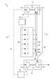
- FIG. 12 shows one side portion of the exhaust manifolds 27, 28, 29, and 30 of the engine 26.
- the engine 26 is a diesel engine, and in this embodiment, an in-line eight-cylinder engine having eight cylinders.
- there are four cylinder groups in this embodiment, the first, eighth cylinder, second, seventh cylinder, third, sixth cylinder, and fourth cylinder) composed of cylinders in the same phase of the engine 26.
- the exhaust manifolds 27, 28, 29, and 30 are independently connected to the fifth cylinder). That is, the exhaust manifold 27 exhausts from the first and eighth cylinders, the exhaust manifold 28 exhausts from the second and seventh cylinders, the exhaust manifold 29 exhausts from the third and sixth cylinders, and the exhaust manifold 30. Exhausts exhaust from the fourth and fifth cylinders together.
- a connecting pipe 31 (shaded portion) is detachably connected to the exhaust manifold 27, 28, 29, 30 at the end (one side end) opposite to the supercharger 3. Has been.
- the connecting pipe 31 includes a bent pipe 31a, a first on-off valve 31b, a first branch pipe 31c, a second on-off valve 31d, a second branch pipe 31e, a third on-off valve 31f, and an extension pipe 31g.
- the bent pipe 31a, the first on-off valve 31b, the first branch pipe 31c, the second on-off valve 31d, the second branch pipe 31e, the third on-off valve 31f, and the extension pipe 31g are connected to the exhaust manifolds 27, 28, 29, and 30. It is configured to be detachable. By being configured in this way, the connecting pipe 31 is configured so that three or more independent exhaust manifolds can be connected to each other.
- the exhaust manifold 27 and the exhaust manifold 28 adjacent to each other are connected to one end portion of the exhaust manifold 27 at one end portion of the bent pipe 31a, and to the other end portion of the bent tube 31a at the first on-off valve 31b and first exhaust valve 31a.
- the exhaust manifold 28 is connected via the branch pipe 31c.
- the adjacent exhaust manifold 28 and exhaust manifold 29 are connected to the first branch pipe 31c connected to the exhaust manifold 28 via the second on-off valve 31d and the second branch pipe 31e.
- the adjacent exhaust manifold 29 and exhaust manifold 30 are connected to a second branch pipe 31e connected to the exhaust manifold 29 via a third on-off valve 31f and an extension pipe 31g. That is, the exhaust manifolds 27, 28, 29, and 30 are connected to each other by the connecting pipe 31.
- one end portions of the exhaust manifolds 27, 28, 29, and 30 are connected by the connecting pipe 31. That is, the connecting pipe 31 is intensively arranged at one end of each exhaust manifold 27, 28, 29, 30. As a result, even when three or more exhaust manifolds 27, 28, 29, and 30 are connected to each other, the engine 26 attaches / detaches the connecting pipe 31, and the first on-off valve 31b, the second on-off valve 31d, and the third on-off valve 31f. Exhaust manifolds 27, 28, 29, and 30 that can be switched between a dynamic pressure supercharging method and a static pressure supercharging method with a configuration that allows easy maintenance can be configured.
- the engine 1 is a diesel engine, and in this embodiment, an in-line eight-cylinder engine having eight cylinders.
- an in-line eight-cylinder engine having one stage supercharger 3 is used, but the present invention is not limited to this, and a plurality of superchargers 3 (for example, two-stage superchargers) are provided. Any multi-cylinder engine with eight or more cylinders may be used.
- Engine 1 rotates the output shaft by mixing external air and fuel supplied from fuel injection valve 44 in each cylinder 1a and burning them.
- the engine 1 includes an intake device 2 that takes in outside air and an exhaust device 7 that discharges exhaust to the outside.
- the engine 1 also includes a rotation speed detection sensor 42, an injection amount detection sensor 43 of the fuel injection valve 44, and an ECU 41 that is a control device.
- the exhaust device 7 includes exhaust manifolds 27, 28, 29, and 30 and a turbine section 3 b of the supercharger 3.
- the exhaust manifolds 27, 28, 29, and 30 include four cylinder groups (in this embodiment, the first, eighth cylinder, second, seventh cylinder, third, sixth, Exhaust manifolds 27, 28, 29, and 30 are independently connected to the cylinder and the fourth and fifth cylinders). That is, the exhaust manifold 27 exhausts from the first and eighth cylinders, the exhaust manifold 28 exhausts from the second and seventh cylinders, the exhaust manifold 29 exhausts from the third and sixth cylinders, and the exhaust manifold 30. Exhausts exhaust from the fourth and fifth cylinders together.
- the exhaust manifolds 27, 28, 29, and 30 are detachably connected with connecting pipes 12 (shaded portions) at end portions (one side end portions).
- the exhaust manifolds 27, 28, 29, and 30 are connected to the supercharger 3 at the other end.
- the connecting device 12 includes a bent pipe 31a, an on-off valve 31b, a branch pipe 31c, an on-off valve 31d, a branch pipe 31e, an on-off valve 31f, and an extension pipe 31g.
- the bent pipe 31a, the open / close valve 31b, the branch pipe 31c, the open / close valve 31d, the branch pipe 31e, the open / close valve 31f, and the extension pipe 31g are configured to be detachable from each other in addition to the exhaust manifolds 27, 28, 29, and 30. By being configured in this way, the connecting device 12 is configured to be able to connect three or more independent exhaust manifolds to each other.
- one end of the bent pipe 31a is connected to one end of the exhaust manifold 27, and an open / close valve 31b and a branch pipe 31c are connected to the other end of the bent pipe 31a.
- the exhaust manifold 28 is connected through the vias.
- the adjacent exhaust manifold 28 and exhaust manifold 29 are connected to a branch pipe 31c connected to the exhaust manifold 28 via an on-off valve 31d and a branch pipe 31e.
- the adjacent exhaust manifold 29 and exhaust manifold 30 are connected to a branch pipe 31e connected to the exhaust manifold 29 via an on-off valve and an extension pipe 31g. That is, the exhaust manifolds 27, 28, 29, and 30 are connected to each other by the connecting device 12.
- the exhaust manifolds 27, 28, 29, and 30 are connected to each other by the connecting device 12 at one end. That is, the coupling device 12 is concentratedly arranged at one end of each exhaust manifold 27, 28, 29, 30.
- the exhaust device 7 can be divided into a dynamic pressure supercharging method and a static pressure supercharging method with a configuration in which the connecting device 12 can be attached and detached and maintenance of the on-off valve 31b, on-off valve 31d and on-off valve 31f is easy.
- Switchable exhaust manifolds 27, 28, 29, and 30 can be configured.
- the turbine section 3b of the supercharger 3 generates rotational power by the pressure of the exhaust.
- the turbine section 3b is connected to the compressor section 3a by a connecting shaft 3c and is configured to be able to transmit rotational power to the compressor section 3a.
- the exhaust manifolds 27, 28, 29, and 30 are connected to the turbine section 3b. Further, the turbine part 3 b is communicated to the outside through the exhaust pipe 13.
- the intake device 2 the compressor section 3a, the supply pipe 4, the intercooler 5, and the supply manifold 6 of the supercharger 3 are connected in order from the upstream side (external). Further, the exhaust device 7 is connected to the exhaust manifolds 27, 28, 29, and 30 from the upstream side (engine 1), the turbine section 3b of the supercharger 3, and the exhaust pipe 13 in this order.
- the exhaust device 7 when all the on-off valves 31 b, 31 d, and 31 f are closed, the exhaust manifolds 27, 28, 29, and 30 are independently connected to the turbine unit 3 b of the supercharger 3. As a result, the exhaust device 7 constitutes an exhaust manifold corresponding to the dynamic pressure supercharging method.
- the exhaust device 7 when some of the on-off valves 31b and 31f are opened, the exhaust manifold 27 and the exhaust manifold 28 are communicated, and the exhaust manifold 29 and the exhaust manifold 30 are communicated. That is, the exhaust manifolds 27 and 28 communicated with the exhaust manifolds 29 and 30 communicated with each other are independently connected to the turbine section 3 b of the supercharger 3.
- the exhaust device 7 includes exhaust manifolds 27 and 28 and exhaust manifolds 29 and 30 corresponding to two sets of static pressure supercharging systems.
- the exhaust device 7 when some of the on-off valves 31b and 31d are opened, the exhaust manifold 27, the exhaust manifold 28, and the exhaust manifold 29 are communicated with each other. That is, the exhaust manifolds 27, 28, and 29 and the exhaust manifold 30 that are communicated with each other are independently connected to the turbine section 3b of the supercharger 3.
- the exhaust device 7 is configured by mixing the exhaust manifolds 27, 28, and 29 corresponding to the static pressure supercharging method and the exhaust manifold 30 corresponding to the dynamic pressure supercharging method.
- the exhaust device 7 is connected to the turbine section 3b of the supercharger 3 in a state where the exhaust manifolds 27, 28, 29, and 30 are communicated when all the on-off valves are opened. That is, the exhaust device 7 includes exhaust manifolds 27, 28, 29, and 30 corresponding to the static pressure supercharging method.
- the rotation speed detection sensor 42 detects a rotation speed N that is the engine rotation speed of the engine 1.
- the rotation speed detection sensor 42 includes a sensor and a pulsar, and is provided on the output shaft of the engine 1.
- the rotational speed detection sensor 42 is composed of a sensor and a pulsar, but any sensor capable of detecting the rotational speed N may be used.
- the injection amount detection sensor 43 detects an injection amount F of fuel injected from the fuel injection valve 44.
- the injection amount detection sensor 43 is provided in the middle of a fuel supply pipe (not shown).
- the injection amount detection sensor 43 is composed of a flow rate sensor.
- the injection amount detection sensor 43 is constituted by a flow rate sensor, but the present invention is not limited to this, and any device that can detect the fuel injection amount F may be used.
- the ECU 41 controls the engine 1. Specifically, the engine 1 body and the on-off valves 31b, 31d, and 31f are controlled.
- the ECU 41 stores various programs and data for controlling the engine 1.
- the ECU 41 may be configured such that a CPU, a ROM, a RAM, an HDD, and the like are connected by a bus, or may be configured by a one-chip LSI or the like.
- ECU41 is connected to the rotation speed detection sensor 42, and can acquire the rotation speed N which the rotation speed detection sensor 42 detects.
- the ECU 41 is connected to the fuel injection valve 44 and can control the fuel injection valve 44.
- ECU41 is connected to the injection quantity detection sensor 43, and can acquire the injection quantity F which the injection quantity detection sensor 43 detects.
- the ECU 41 is connected to the open / close valves 31b, 31d, 31f of the exhaust manifolds 27, 28, 29, 30 and can control the open / close states of the open / close valves 31b, 31d, 31f.
- the ECU 41 stores an output torque map M1 for calculating the output torque T of the engine 1 based on the acquired rotation speed N and the acquired injection amount F. Further, the ECU 41 stores a load factor calculation map M2 for calculating the load factor L (n) of the engine 1 based on the acquired rotation speed N and the calculated output torque T. Here, the load factor L (n) is the nth calculated load factor L.
- the ECU 41 also has an on / off valve map for determining the on / off state of the on / off valves 31b, 31d, and 31f that minimizes the fuel consumption FC of the engine 1 based on the acquired rotation speed N and the calculated load factor L (n). M3 is stored.
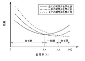
- the on-off valve map M3 stored in the ECU 41 will be described with reference to FIGS.
- the on-off valve map M3 is a load factor that serves as a reference for determining the on-off state of the on-off valves 31b, 31d, 31f based on the acquired rotation speed N and the calculated load factor L (n) of the engine 1.
- One reference value La and second reference value Lb are shown.
- the first reference value La is the minimum fuel consumption FC of the engine 1 when all of the on / off valves 31b, 31d, 31f are closed at an arbitrary rotational speed N of the engine 1.
- the second reference value Lb is a load factor L (n at which the fuel consumption FC of the engine 1 is minimized when some of the on / off valves 31b, 31d, 31f are open at an arbitrary rotational speed N.
- the engine 1 minimizes the fuel consumption FC for each arbitrary rotation speed N from the relationship between the load factor L (n) and the first reference value La and the relationship between the load factor L (n) and the second reference value Lb.
- the state of the on-off valve for the purpose is determined.
- an on-off valve map M3 is configured from the first reference value La and the second reference value Lb for each engine speed N. That is, the on-off valve map M3 shows the relationship between the range of the load factor L (n) at which the fuel consumption FC of the engine 1 is minimum for each rotation speed N and the states of the on-off valves 31b, 31d, 31f.
- ECU41 calculates the load factor L (n) of the engine 1 from the output torque map M1 and the load factor calculation map M2 based on the acquired rotation speed N and the acquired injection amount F.
- the ECU 41 determines that the operating state of the engine 1 is constant when the increase / decrease amount per unit time of the load factor L (n) is less than the predetermined value Lc. That is, the ECU 41 determines that the ship 100 is operating in a constant traveling mode in which fuel efficiency is important. Then, the ECU 41 determines the open / close states of the open / close valves 31b, 31d, 31f of the engine 1 from the open / close valve map M3 based on the acquired rotation speed N and the calculated load factor L (n).
- the ECU41 judges that the driving
- step S110 the ECU 41 obtains the rotation speed N detected by the rotation speed detection sensor 42 and the injection amount F detected by the injection amount detection sensor 43, and the process proceeds to step S120.
- step S120 the ECU 41 calculates the output torque T of the engine 1 from the output torque map M1 based on the acquired rotation speed N and the acquired injection amount F, and shifts the step to step S130.
- step S130 the ECU 41 calculates the load factor L (n) of the engine 1 from the load factor calculation map M2 based on the acquired rotation speed N and the calculated output torque T, and the step proceeds to step S140.
- step S140 the ECU 41 determines whether or not the absolute value of the difference between the calculated L (n) and L (n-1) is less than a predetermined value Lc. As a result, when it is determined that the absolute value of the difference between the calculated L (n) and L (n ⁇ 1) is less than the predetermined value Lc, the ECU 41 proceeds to step S150. On the other hand, when it is determined that the absolute value of the difference between the calculated L (n) and L (n ⁇ 1) is not less than the predetermined value Lc, that is, the difference between the calculated L (n) and L (n ⁇ 1). When it is determined that the absolute value of is greater than or equal to the predetermined value Lc, the ECU 41 proceeds to step S560.
- step S150 the ECU 41 determines whether or not the state where the absolute value of the difference between the calculated L (n) and L (n-1) is less than the predetermined value Lc has continued for a predetermined time T or longer.
- the ECU 41 shifts the step to step S200.
- the ECU 41 proceeds to step S560.
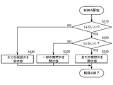
- step S200 the ECU 41 starts the on-off valve control A and shifts the step to step 210 (see FIG. 18).
- step S210 the ECU 41 determines whether or not the calculated L (n) is greater than or equal to the first reference value La. As a result, when it is determined that the calculated L (n) is greater than or equal to the first reference value La, the ECU 41 proceeds to step S220. On the other hand, when it is determined that the calculated L (n) is not greater than or equal to the first reference value La, that is, when it is determined that the calculated L (n) is less than the first reference value La, the ECU 41 proceeds to step S430. Transition.
- step S220 the ECU 41 determines whether or not the calculated L (n) is greater than or equal to the second reference value Lb. As a result, when it is determined that the calculated L (n) is equal to or greater than the second reference value Lb, the ECU 41 shifts the step to step S230. On the other hand, when it is determined that the calculated L (n) is not equal to or greater than the second reference value Lb, that is, it is determined that the calculated L (n) is equal to or greater than the first reference value La and less than the second reference value Lb. In this case, the ECU 41 shifts the step to step S330.
- step S230 the ECU 41 opens all the on-off valves 31b, 31d, 31f of the exhaust manifold, ends the on-off valve control A, and proceeds to step S110 (see FIG. 17).
- step S330 the ECU 41 opens a part of the on-off valves 31b and 31f or the on-off valves 31b and 31d of the exhaust manifold, ends the on-off valve control A, and shifts the step to step S110 (see FIG. 17).
- step S430 the ECU 41 closes all the on-off valves 31b, 31d, 31f of the exhaust manifold, ends the on-off valve control A, and shifts the step to step S110 (see FIG. 17).
- step S560 the ECU 41 closes all the on-off valves 31b, 31d, 31f of the exhaust manifold, and moves the step to step S170.
- the engine 1 switches the open / close states of the open / close valves 31b, 31d, and 31f of the exhaust manifolds 27, 28, 29, and 30 based on the rotational speed N and the load factor L (n).
- the pressure state of the exhaust gas supplied to the feeder 3 is changed.
- the responsiveness of the supercharger 3 when the supercharger 3 rotates at a low speed and the fuel efficiency of the engine 1 when the supercharger 3 rotates at a high speed can be improved.
- the load state of the engine 1 fluctuates, the responsiveness of the supercharger 3 is improved by switching all the on-off valves 31b, 31d, 31f to the closed state. Thereby, generation
- the present invention can be used for the technology of a supercharged engine.
Landscapes
- Engineering & Computer Science (AREA)
- Chemical & Material Sciences (AREA)
- Combustion & Propulsion (AREA)
- Mechanical Engineering (AREA)
- General Engineering & Computer Science (AREA)
- Supercharger (AREA)
- Exhaust Silencers (AREA)
Abstract
Priority Applications (4)
| Application Number | Priority Date | Filing Date | Title |
|---|---|---|---|
| US15/031,720 US9982591B2 (en) | 2013-10-25 | 2014-10-22 | Engine |
| EP14856433.9A EP3075979B1 (fr) | 2013-10-25 | 2014-10-22 | Moteur |
| CN201480058737.7A CN105849385B (zh) | 2013-10-25 | 2014-10-22 | 发动机 |
| KR1020167013718A KR101836019B1 (ko) | 2013-10-25 | 2014-10-22 | 엔진 |
Applications Claiming Priority (4)
| Application Number | Priority Date | Filing Date | Title |
|---|---|---|---|
| JP2013-222805 | 2013-10-25 | ||
| JP2013-222806 | 2013-10-25 | ||
| JP2013222805A JP6073772B2 (ja) | 2013-10-25 | 2013-10-25 | エンジン |
| JP2013222806A JP6148596B2 (ja) | 2013-10-25 | 2013-10-25 | エンジン |
Publications (1)
| Publication Number | Publication Date |
|---|---|
| WO2015060321A1 true WO2015060321A1 (fr) | 2015-04-30 |
Family
ID=52992914
Family Applications (1)
| Application Number | Title | Priority Date | Filing Date |
|---|---|---|---|
| PCT/JP2014/078019 WO2015060321A1 (fr) | 2013-10-25 | 2014-10-22 | Moteur |
Country Status (5)
| Country | Link |
|---|---|
| US (1) | US9982591B2 (fr) |
| EP (1) | EP3075979B1 (fr) |
| KR (1) | KR101836019B1 (fr) |
| CN (1) | CN105849385B (fr) |
| WO (1) | WO2015060321A1 (fr) |
Families Citing this family (3)
| Publication number | Priority date | Publication date | Assignee | Title |
|---|---|---|---|---|
| CN108167065A (zh) * | 2017-12-26 | 2018-06-15 | 潍柴动力股份有限公司 | 一种多缸发动机的排气系统 |
| US10690092B2 (en) * | 2018-04-12 | 2020-06-23 | Caterpillar Inc. | EGR system for compound turbocharged engine system |
| CN112513439B (zh) * | 2018-09-28 | 2022-05-17 | Fb设计有限公司 | 改进的涡轮增压器组件 |
Citations (5)
| Publication number | Priority date | Publication date | Assignee | Title |
|---|---|---|---|---|
| JPS5413822A (en) * | 1977-04-21 | 1979-02-01 | Audi Ag | Exhaust gas conduit device |
| JPS60247006A (ja) * | 1984-05-22 | 1985-12-06 | Yoichi Yamazaki | 多気筒エンジンの排気装置 |
| JP2001164934A (ja) * | 1999-12-13 | 2001-06-19 | Yanmar Diesel Engine Co Ltd | 内燃機関の排気装置 |
| JP2004124749A (ja) * | 2002-09-30 | 2004-04-22 | Mazda Motor Corp | ターボ過給機付エンジンの排気装置 |
| JP2008038657A (ja) | 2006-08-02 | 2008-02-21 | Yanmar Co Ltd | 過給機付内燃機関の排気制御方法 |
Family Cites Families (24)
| Publication number | Priority date | Publication date | Assignee | Title |
|---|---|---|---|---|
| US2660031A (en) * | 1951-01-03 | 1953-11-24 | American Locomotive Co | Exhaust manifold for internalcombustion engines |
| US2773348A (en) * | 1952-03-27 | 1956-12-11 | Nordberg Manufacturing Co | Turbo-charger system, involving plural turbine driven superchargers |
| US2852910A (en) * | 1953-12-29 | 1958-09-23 | Gen Motors Corp | Exhaust manifold |
| US3077071A (en) * | 1960-04-28 | 1963-02-12 | Nordberg Manufacturing Co | Exhaust system for turbocharged engine |
| US3180077A (en) * | 1962-03-20 | 1965-04-27 | Ite Circuit Breaker Ltd | Wave machine to initiate scavenging of internal combustion |
| GB1164018A (en) * | 1967-07-11 | 1969-09-10 | Goetaverken Ab | Improvements in or relating to Turbo-Driven Superchargers for Two-Stroke I.C. Engines |
| DE2625788B1 (de) * | 1976-06-09 | 1977-08-11 | Motoren Werke Mannheim Ag | Abgasleitung fuer turboaufgeladene brennkraftmaschinen |
| JP3074863B2 (ja) * | 1991-11-20 | 2000-08-07 | 株式会社日立製作所 | 渦流ブロアの羽根車の製造方法 |
| DE4342572C1 (de) * | 1993-12-14 | 1994-11-24 | Mtu Friedrichshafen Gmbh | Abgasanlage für eine aufgeladene Brennkraftmaschine |
| JP3074863U (ja) | 2000-07-14 | 2001-01-26 | 藤壷技研工業株式会社 | 内燃機関の排気装置 |
| DE10048237A1 (de) * | 2000-09-29 | 2002-04-11 | Daimler Chrysler Ag | Abgasturbolader, aufgeladene Brennkraftmaschine und Verfahren hierzu |
| JP4298972B2 (ja) * | 2002-08-02 | 2009-07-22 | 富士重工業株式会社 | エンジン排気システム及びエンジン排気システムの制御方法 |
| DE102004055571A1 (de) * | 2004-11-18 | 2006-06-08 | Daimlerchrysler Ag | Abgasturbolader für eine Brennkraftmaschine |
| US20060174621A1 (en) * | 2005-02-04 | 2006-08-10 | Kai Chen | Two-turbocharger engine and method |
| DE102005021172A1 (de) * | 2005-05-06 | 2006-11-09 | Daimlerchrysler Ag | Brennkraftmaschine mit Abgasturbolader und Abgasrückführung |
| US7788923B2 (en) * | 2006-02-02 | 2010-09-07 | International Engine Intellectual Property Company, Llc | Constant EGR rate engine and method |
| DE102006019780A1 (de) * | 2006-04-28 | 2007-11-08 | Daimlerchrysler Ag | Abgasturbolader in einer Brennkraftmaschine |
| DE102006022182A1 (de) * | 2006-05-12 | 2007-11-15 | Daimlerchrysler Ag | Brennkraftmaschine mit einem Abgasturbolader und Abgasrückführung |
| US20080000228A1 (en) * | 2006-06-30 | 2008-01-03 | Caterpillar Inc. | System and method for exhaust recirculation |
| JP4215085B2 (ja) * | 2006-09-14 | 2009-01-28 | トヨタ自動車株式会社 | 内燃機関 |
| US7891345B2 (en) * | 2008-08-18 | 2011-02-22 | Caterpillar Inc. | EGR system having multiple discharge locations |
| US8201405B2 (en) * | 2008-12-18 | 2012-06-19 | Caterpillar Inc. | Crossover exhaust duct with front inside passage and rear outside passage |
| EP2246543B1 (fr) * | 2009-04-01 | 2013-09-04 | Ford Global Technologies, LLC | Culasse comprenant deux collecteurs d'échappement et procédé destiné au fonctionnement d'un moteur à combustion interne comprenant une telle culasse |
| US8555638B2 (en) * | 2011-04-14 | 2013-10-15 | Caterpillar Inc. | Internal combustion engine with improved exhaust manifold |
-
2014
- 2014-10-22 CN CN201480058737.7A patent/CN105849385B/zh not_active Expired - Fee Related
- 2014-10-22 US US15/031,720 patent/US9982591B2/en not_active Expired - Fee Related
- 2014-10-22 EP EP14856433.9A patent/EP3075979B1/fr not_active Not-in-force
- 2014-10-22 KR KR1020167013718A patent/KR101836019B1/ko active IP Right Grant
- 2014-10-22 WO PCT/JP2014/078019 patent/WO2015060321A1/fr active Application Filing
Patent Citations (5)
| Publication number | Priority date | Publication date | Assignee | Title |
|---|---|---|---|---|
| JPS5413822A (en) * | 1977-04-21 | 1979-02-01 | Audi Ag | Exhaust gas conduit device |
| JPS60247006A (ja) * | 1984-05-22 | 1985-12-06 | Yoichi Yamazaki | 多気筒エンジンの排気装置 |
| JP2001164934A (ja) * | 1999-12-13 | 2001-06-19 | Yanmar Diesel Engine Co Ltd | 内燃機関の排気装置 |
| JP2004124749A (ja) * | 2002-09-30 | 2004-04-22 | Mazda Motor Corp | ターボ過給機付エンジンの排気装置 |
| JP2008038657A (ja) | 2006-08-02 | 2008-02-21 | Yanmar Co Ltd | 過給機付内燃機関の排気制御方法 |
Also Published As
| Publication number | Publication date |
|---|---|
| US9982591B2 (en) | 2018-05-29 |
| EP3075979B1 (fr) | 2019-08-14 |
| CN105849385B (zh) | 2018-06-26 |
| KR20160081932A (ko) | 2016-07-08 |
| KR101836019B1 (ko) | 2018-03-07 |
| EP3075979A4 (fr) | 2017-05-31 |
| US20160265423A1 (en) | 2016-09-15 |
| CN105849385A (zh) | 2016-08-10 |
| EP3075979A1 (fr) | 2016-10-05 |
Similar Documents
| Publication | Publication Date | Title |
|---|---|---|
| US10513976B2 (en) | Engine system | |
| CN107762620B (zh) | 发动机系统 | |
| EP2683925B1 (fr) | Procédé pour la mise à niveau d'un moteur, matériel pour la mise à niveau d'un moteur et moteur à combustion interne | |
| JP6135693B2 (ja) | 過給エンジンの制御装置 | |
| WO2015060321A1 (fr) | Moteur | |
| JP5114500B2 (ja) | 内燃機関用の排ガスシステム | |
| JP6073772B2 (ja) | エンジン | |
| JP6003239B2 (ja) | 内燃機関 | |
| JP2009030493A (ja) | 内燃機関の過給システム | |
| JP6298744B2 (ja) | エンジン | |
| CN109404158B (zh) | 一种v型大功率中速柴油机 | |
| KR20140087865A (ko) | 터보 차져 시스템 | |
| JP6148596B2 (ja) | エンジン | |
| JP2005291044A (ja) | ターボ式過給機付き多気筒エンジン | |
| KR102383215B1 (ko) | 엔진 시스템 | |
| JP6756531B2 (ja) | 内燃機関の制御方法及び制御装置 | |
| US10054039B2 (en) | Turbocharger system for an engine | |
| US20120204561A1 (en) | Kit for producing automobiles with different engine variants | |
| JP2008057345A (ja) | 吸気装置 | |
| JP4375089B2 (ja) | ターボ式過給機付き多気筒エンジン | |
| JP2002364372A (ja) | ディーゼル機関の過給装置 | |
| JPS6019916A (ja) | タ−ボ過給機付エンジン | |
| JP2012132337A (ja) | 過給機付き内燃機関の制御装置 | |
| JP2020090946A (ja) | エンジン | |
| KR20170067510A (ko) | 엔진 시스템 |
Legal Events
| Date | Code | Title | Description |
|---|---|---|---|
| 121 | Ep: the epo has been informed by wipo that ep was designated in this application |
Ref document number: 14856433 Country of ref document: EP Kind code of ref document: A1 |
|
| WWE | Wipo information: entry into national phase |
Ref document number: 15031720 Country of ref document: US |
|
| NENP | Non-entry into the national phase |
Ref country code: DE |
|
| REEP | Request for entry into the european phase |
Ref document number: 2014856433 Country of ref document: EP |
|
| WWE | Wipo information: entry into national phase |
Ref document number: 2014856433 Country of ref document: EP |
|
| ENP | Entry into the national phase |
Ref document number: 20167013718 Country of ref document: KR Kind code of ref document: A |