WO2015060312A1 - 表示装置、電子機器、および表示装置の制御方法 - Google Patents
表示装置、電子機器、および表示装置の制御方法 Download PDFInfo
- Publication number
- WO2015060312A1 WO2015060312A1 PCT/JP2014/077990 JP2014077990W WO2015060312A1 WO 2015060312 A1 WO2015060312 A1 WO 2015060312A1 JP 2014077990 W JP2014077990 W JP 2014077990W WO 2015060312 A1 WO2015060312 A1 WO 2015060312A1
- Authority
- WO
- WIPO (PCT)
- Prior art keywords
- period
- polarity
- refresh
- vertical period
- vertical
- Prior art date
- Legal status (The legal status is an assumption and is not a legal conclusion. Google has not performed a legal analysis and makes no representation as to the accuracy of the status listed.)
- Ceased
Links
Images






Classifications
-
- G—PHYSICS
- G09—EDUCATION; CRYPTOGRAPHY; DISPLAY; ADVERTISING; SEALS
- G09G—ARRANGEMENTS OR CIRCUITS FOR CONTROL OF INDICATING DEVICES USING STATIC MEANS TO PRESENT VARIABLE INFORMATION
- G09G3/00—Control arrangements or circuits, of interest only in connection with visual indicators other than cathode-ray tubes
- G09G3/20—Control arrangements or circuits, of interest only in connection with visual indicators other than cathode-ray tubes for presentation of an assembly of a number of characters, e.g. a page, by composing the assembly by combination of individual elements arranged in a matrix no fixed position being assigned to or needed to be assigned to the individual characters or partial characters
- G09G3/34—Control arrangements or circuits, of interest only in connection with visual indicators other than cathode-ray tubes for presentation of an assembly of a number of characters, e.g. a page, by composing the assembly by combination of individual elements arranged in a matrix no fixed position being assigned to or needed to be assigned to the individual characters or partial characters by control of light from an independent source
- G09G3/36—Control arrangements or circuits, of interest only in connection with visual indicators other than cathode-ray tubes for presentation of an assembly of a number of characters, e.g. a page, by composing the assembly by combination of individual elements arranged in a matrix no fixed position being assigned to or needed to be assigned to the individual characters or partial characters by control of light from an independent source using liquid crystals
-
- G—PHYSICS
- G09—EDUCATION; CRYPTOGRAPHY; DISPLAY; ADVERTISING; SEALS
- G09G—ARRANGEMENTS OR CIRCUITS FOR CONTROL OF INDICATING DEVICES USING STATIC MEANS TO PRESENT VARIABLE INFORMATION
- G09G3/00—Control arrangements or circuits, of interest only in connection with visual indicators other than cathode-ray tubes
- G09G3/20—Control arrangements or circuits, of interest only in connection with visual indicators other than cathode-ray tubes for presentation of an assembly of a number of characters, e.g. a page, by composing the assembly by combination of individual elements arranged in a matrix no fixed position being assigned to or needed to be assigned to the individual characters or partial characters
- G09G3/2092—Details of a display terminals using a flat panel, the details relating to the control arrangement of the display terminal and to the interfaces thereto
-
- G—PHYSICS
- G09—EDUCATION; CRYPTOGRAPHY; DISPLAY; ADVERTISING; SEALS
- G09G—ARRANGEMENTS OR CIRCUITS FOR CONTROL OF INDICATING DEVICES USING STATIC MEANS TO PRESENT VARIABLE INFORMATION
- G09G3/00—Control arrangements or circuits, of interest only in connection with visual indicators other than cathode-ray tubes
- G09G3/20—Control arrangements or circuits, of interest only in connection with visual indicators other than cathode-ray tubes for presentation of an assembly of a number of characters, e.g. a page, by composing the assembly by combination of individual elements arranged in a matrix no fixed position being assigned to or needed to be assigned to the individual characters or partial characters
- G09G3/34—Control arrangements or circuits, of interest only in connection with visual indicators other than cathode-ray tubes for presentation of an assembly of a number of characters, e.g. a page, by composing the assembly by combination of individual elements arranged in a matrix no fixed position being assigned to or needed to be assigned to the individual characters or partial characters by control of light from an independent source
- G09G3/36—Control arrangements or circuits, of interest only in connection with visual indicators other than cathode-ray tubes for presentation of an assembly of a number of characters, e.g. a page, by composing the assembly by combination of individual elements arranged in a matrix no fixed position being assigned to or needed to be assigned to the individual characters or partial characters by control of light from an independent source using liquid crystals
- G09G3/3611—Control of matrices with row and column drivers
- G09G3/3614—Control of polarity reversal in general
-
- G—PHYSICS
- G09—EDUCATION; CRYPTOGRAPHY; DISPLAY; ADVERTISING; SEALS
- G09G—ARRANGEMENTS OR CIRCUITS FOR CONTROL OF INDICATING DEVICES USING STATIC MEANS TO PRESENT VARIABLE INFORMATION
- G09G3/00—Control arrangements or circuits, of interest only in connection with visual indicators other than cathode-ray tubes
- G09G3/20—Control arrangements or circuits, of interest only in connection with visual indicators other than cathode-ray tubes for presentation of an assembly of a number of characters, e.g. a page, by composing the assembly by combination of individual elements arranged in a matrix no fixed position being assigned to or needed to be assigned to the individual characters or partial characters
- G09G3/34—Control arrangements or circuits, of interest only in connection with visual indicators other than cathode-ray tubes for presentation of an assembly of a number of characters, e.g. a page, by composing the assembly by combination of individual elements arranged in a matrix no fixed position being assigned to or needed to be assigned to the individual characters or partial characters by control of light from an independent source
- G09G3/36—Control arrangements or circuits, of interest only in connection with visual indicators other than cathode-ray tubes for presentation of an assembly of a number of characters, e.g. a page, by composing the assembly by combination of individual elements arranged in a matrix no fixed position being assigned to or needed to be assigned to the individual characters or partial characters by control of light from an independent source using liquid crystals
- G09G3/3611—Control of matrices with row and column drivers
- G09G3/3648—Control of matrices with row and column drivers using an active matrix
-
- G—PHYSICS
- G09—EDUCATION; CRYPTOGRAPHY; DISPLAY; ADVERTISING; SEALS
- G09G—ARRANGEMENTS OR CIRCUITS FOR CONTROL OF INDICATING DEVICES USING STATIC MEANS TO PRESENT VARIABLE INFORMATION
- G09G2320/00—Control of display operating conditions
- G09G2320/02—Improving the quality of display appearance
- G09G2320/0247—Flicker reduction other than flicker reduction circuits used for single beam cathode-ray tubes
-
- G—PHYSICS
- G09—EDUCATION; CRYPTOGRAPHY; DISPLAY; ADVERTISING; SEALS
- G09G—ARRANGEMENTS OR CIRCUITS FOR CONTROL OF INDICATING DEVICES USING STATIC MEANS TO PRESENT VARIABLE INFORMATION
- G09G2320/00—Control of display operating conditions
- G09G2320/02—Improving the quality of display appearance
- G09G2320/0257—Reduction of after-image effects
-
- G—PHYSICS
- G09—EDUCATION; CRYPTOGRAPHY; DISPLAY; ADVERTISING; SEALS
- G09G—ARRANGEMENTS OR CIRCUITS FOR CONTROL OF INDICATING DEVICES USING STATIC MEANS TO PRESENT VARIABLE INFORMATION
- G09G2330/00—Aspects of power supply; Aspects of display protection and defect management
- G09G2330/02—Details of power systems and of start or stop of display operation
- G09G2330/021—Power management, e.g. power saving
-
- G—PHYSICS
- G09—EDUCATION; CRYPTOGRAPHY; DISPLAY; ADVERTISING; SEALS
- G09G—ARRANGEMENTS OR CIRCUITS FOR CONTROL OF INDICATING DEVICES USING STATIC MEANS TO PRESENT VARIABLE INFORMATION
- G09G2340/00—Aspects of display data processing
- G09G2340/04—Changes in size, position or resolution of an image
- G09G2340/0407—Resolution change, inclusive of the use of different resolutions for different screen areas
- G09G2340/0435—Change or adaptation of the frame rate of the video stream
Definitions
- the present invention relates to a display device, an electronic device, and a display device control method.
- liquid crystal display devices typified by liquid crystal display devices
- a typical mounting form of such a display device is, for example, a mobile phone, a smartphone, a notebook PC (Personal Computer), or the like.
- electronic paper which is a thinner display device, is expected to develop and spread rapidly. Under such circumstances, it is a common problem to reduce power consumption in various display devices.
- Patent Document 1 describes a liquid crystal display in which when a stripe does not exist in an image over a series of frames, it is determined that the frame does not have a feature that easily causes flicker, and the refresh rate is reduced.
- Patent Document 2 describes a liquid crystal display that performs frame rate conversion and does not perform polarity conversion when an interpolation frame is displayed.
- Japanese Patent Publication Japanese Unexamined Patent Application Publication No. 2009-251607 (Published October 29, 2009)” Japanese Patent Publication “JP 2013-174916 A (published on September 5, 2013)”
- an oxide semiconductor liquid crystal display panel in which a TFT is formed of an oxide semiconductor using indium (In), gallium (Ga), and zinc (Zn) has been realized.
- a TFT formed using an oxide semiconductor current leakage in an off state is small. Therefore, in the oxide semiconductor liquid crystal display panel, it is not necessary to refresh the screen at 60 Hz as in the conventional case, and the refresh rate can be reduced to about 1 Hz. Therefore, in the oxide semiconductor liquid crystal display panel, refresh can be paused during a period in which no image is updated. Therefore, power consumption can be reduced.
- a display device that suppresses power consumption and performs favorable display can be realized.
- a display device is a display device in which the polarity of a data signal written to a pixel is inverted in accordance with refresh of the display screen, and each refresh period is set to the refresh period.
- a refresh control unit that provides a vertical period during which the refresh is suspended in a period in which no image is updated, and a first polarity in a second vertical period in which the refresh is performed immediately before the first period in which no image is updated.
- a polarity determination unit for determining whether or not the second polarity of the third vertical period for suspending the refresh immediately before the second vertical period is the same, and the first polarity and the first polarity When the two polarities are the same, the refresh control unit performs an additional vertical operation for performing the refresh with a polarity different from the first polarity in the first period. It is characterized by providing between.
- a control method for a display device is a control method for a display device in which the polarity of a data signal written to a pixel is inverted in response to refresh of the display screen.
- a vertical period for suspending the refresh is provided, and the first polarity of the second vertical period in which the refresh is performed immediately before the first period in which the image is not updated, It is determined whether or not the second polarity of the third vertical period in which the refresh immediately preceding the second vertical period is paused is the same, and the first polarity and the second polarity are the same.
- an additional vertical period in which the refresh is performed with a polarity different from the first polarity is provided.
- the present invention it is possible to prevent flicker from being visually recognized by a user by preventing the polarity of pixels from being biased to one side over a long period. Therefore, power consumption can be reduced by providing a vertical period in which display quality is maintained and refresh is paused.
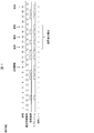
- 10 is a timing chart of image update and refresh in Reference Example 1.
- 10 is a timing chart of image update and refresh in Reference Example 2.
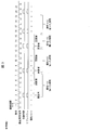
- 4 is a timing chart of image update and refresh in the display device according to the embodiment of the present invention.
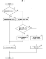
- It is a flowchart which shows the display control flow of the display control part of the said display apparatus.
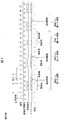
- 6 is a timing chart of image update and refresh in an operation example of one embodiment of the present invention. 6 is a timing chart of image update and refresh in a display device according to another embodiment of the present invention.
- It is a flowchart which shows the display control flow of the display control part of the said display apparatus. 12 is a timing chart of image update and refresh in a display device according to still another embodiment of the present invention. It is a block diagram which shows the structure of the display apparatus of further another embodiment of this invention. It is a block diagram which shows the structure of the display apparatus of further another embodiment of this invention.
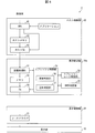
- FIG. 1 is a block diagram showing the configuration of the display device 1 of the present embodiment.
- the display device 1 includes a display unit 10, a display drive unit 20, a display control unit 30, and a host control unit 40.
- the display device 1 is a liquid crystal display device. Note that the present invention is not limited to a liquid crystal display device, and can be applied to a display device that performs polarity inversion.
- the display driving unit 20 is a COG driver mounted on the glass substrate of the display unit 10 by COG (Chip on glass), and drives the display unit 10.
- the host control unit 40 is a control board configured by a control circuit formed on the substrate, and mainly takes control of the host side of the display device 1 (control for electronic devices).
- the display control unit 30 is a control board that is provided separately from the host control unit 40 for image processing or the like for an image to be displayed. In the present embodiment, the display control unit 30 determines whether or not to refresh (write to a pixel) in each vertical period. Thereby, it is possible to reduce the load on the host control unit 40 and to secure the processing capability for causing the host control unit 40 to perform another process (for example, an application process of an electronic device) other than the display.
- the detailed configuration of each part will be described below.
- the display device 1 is a display device in which unnecessary refresh is omitted, that is, the refresh rate changes depending on whether or not an image is updated.
- the display unit 10 includes a display screen having a plurality of pixels, and includes, for example, an oxide semiconductor liquid crystal display panel as an active matrix liquid crystal display panel.
- An oxide semiconductor liquid crystal display panel is a liquid crystal display that employs an oxide semiconductor-TFT (thin film transistor) as a switching element provided corresponding to at least one of a plurality of pixels arranged two-dimensionally. It is a panel.
- An oxide semiconductor-TFT is a TFT in which an oxide semiconductor is used for a semiconductor layer.
- an oxide semiconductor for example, an oxide semiconductor using an oxide of indium, gallium, and zinc (InGaZnO-based oxide semiconductor) is given.
- An oxide semiconductor-TFT has a large current flowing in an on state and a small leak current in an off state. Therefore, by employing an oxide semiconductor-TFT for the switching element, the pixel aperture ratio can be improved and the refresh rate of the screen display can be reduced to about 1 Hz. The reduction of the refresh rate brings about a power saving effect. Note that the improvement in pixel aperture ratio has the effect of brightening the display, or in the case where the display brightness is the same as that of a CG (Continuous Grain) silicon liquid crystal display panel, etc. Bring.
- CG Continuous Grain
- the host control unit 40 includes a CPU 41 (central processing unit), a host memory 42, and a host TG 43 (host timing generator).
- the CPU 41 receives image data to be displayed on the display screen. Further, the CPU 41 receives an image update flag (time reference) indicating the timing for displaying the image data.
- the image data and the image update flag are generated by, for example, an application that is activated and running in the display device 1. Alternatively, the image data and the image update flag are included in data streaming or broadcast waves via the Internet.
- the image data is data representing an image of one frame in the moving image.
- the CPU 41 writes the received image data into the host memory 42.
- the CPU instructs the host TG 43 to perform image update based on the image update flag.
- the CPU 41 may generate image data to be displayed based on an instruction from an application or the like.
- the host memory 42 is a storage device composed of VRAM (Video Random Access Memory) or the like.
- the host TG 43 When the host TG 43 receives an image update instruction from the CPU 41, the host TG 43 acquires the image data from the host memory 42 and transfers the image data to the display control unit 30. The host TG 43 transfers the image data of the updated frame to the display control unit 30 only when the displayed image needs to be updated (that is, only when the content of the image changes). The transfer of the image data is performed according to the data communication specification of the mobile device such as MIPI (Mobile / Industry / Processor / Interface). The host TG 43 transfers the synchronization signal together with the image data to the display control unit 30.
- MIPI Mobile / Industry / Processor / Interface
- the display control unit 30 includes an image processing unit 31, a memory 32, a TG 33 (timing generator), a refresh control unit 34, and a polarity determination unit 35.
- the image processing unit 31 performs image processing such as color adjustment on the image data received from the host control unit 40.
- the image processing unit 31 writes the image data that has undergone image processing in the memory 32.
- the image processing unit 31 notifies the refresh control unit 34 that the image is updated.
- the memory 32 stores the written image data until the image data is overwritten (updated) next time.
- the refresh control unit 34 determines whether or not to refresh the display screen for each vertical period. That is, the refresh control unit 34 determines whether or not to write data signals to a plurality of pixels of the display unit 10 for each vertical period.
- the refresh control unit 34 includes an update determination unit 36 and an addition determination unit 37.
- the update determination unit 36 of the refresh control unit 34 sets each vertical period included in a period in which the image is updated (the content of the displayed image is changed) as a driving vertical period in which refresh is performed.
- the update determination unit 36 temporarily sets each vertical period included in a period in which no image is updated as a pause vertical period in which refresh is paused. Whether or not image update is performed can be determined based on whether or not image data has been received, or can be determined based on a notification from the host control unit 40 that there is no image update.
- the polarity determination unit 35 selects the first based on the past drive vertical period and pause vertical period set by the refresh control unit 34. It is determined whether the polarity and the second polarity are the same.
- the first polarity is the polarity of the drive vertical period immediately before the period in which the image is not updated.
- the second polarity is the polarity of the nearest rest vertical period before the drive vertical period. For example, when a plurality of drive vertical periods are continuous, the second polarity is the polarity of the pause vertical period immediately before the plurality of continuous drive vertical periods. Detailed processing of the polarity determination unit 35 will be described later.
- the polarity determination unit 35 notifies the addition determination unit 37 of the refresh control unit 34 of the determination result.
- the addition determination unit 37 of the refresh control unit 34 performs an additional drive vertical period in which refresh is performed with a polarity different from the first polarity in the period in which the image is not updated. (Additional vertical period) is provided.
- the addition determination unit 37 sets the first vertical period (the pause vertical period of interest following the drive vertical period) in the period in which no image update is performed as the additional drive vertical period in which refresh is performed. Note that, when the first polarity and the second polarity are different, the refresh control unit 34 does not provide an additional drive vertical period in the period in which the image update is not performed.
- the refresh control unit 34 notifies the TG 33 whether or not to perform refresh in each vertical period based on the set drive vertical period, additional drive vertical period, and pause vertical period.
- the TG 33 displays image data in accordance with the refresh timing (vertical period timing) of the display unit 10 based on the setting of the drive vertical period (including the additional drive vertical period) and the pause vertical period of the refresh control unit 34. Transfer to the drive unit 20.
- the TG 33 reads the image data from the memory 32 and transfers the image data to the display drive unit 20 in the drive vertical period in which refresh is performed. On the other hand, the TG 33 does not transfer image data to the display driving unit 20 in the pause vertical period in which no refresh is performed. Further, the TG 33 generates a timing signal for driving the display unit 10 and supplies the timing signal to the source driver 21. Note that the TG 33 may use a synchronization signal input from the host TG 43 in order to generate a timing signal.
- the refresh control unit 34 refreshes the data signal written in the pixel every predetermined period (for example, 0.25 seconds or more).
- a drive vertical period may be set to This is to maintain display quality when a still image is displayed for a long time.
- the display driving unit 20 includes a source driver 21.
- the source driver 21 writes a data signal corresponding to the image data to the pixels of the display unit 10 in accordance with the timing signal.
- the source driver 21 inverts the polarity of the data signal written to the pixel every time refresh is performed.
- the polarity of the data signal (data potential) is a polarity based on the potential of the counter electrode facing the pixel electrode.
- the inversion driving method is not particularly limited. For example, a frame inversion driving method, a column inversion driving method, a row line inversion driving method, or a dot inversion driving method may be used.
- an electronic device that is a host including the display device 1, for example, a mobile phone, a smartphone, a notebook PC (personal computer), a tablet terminal, an electronic book reader, or a PDA (Personal Digital Assistant), etc.
- a mobile phone for example, a smartphone, a notebook PC (personal computer), a tablet terminal, an electronic book reader, or a PDA (Personal Digital Assistant), etc.
- An electronic device that places importance on portability using a battery as a power source can be given.
- FIG. 2 is a timing chart of image update and refresh in Reference Example 1 for comparison.
- the horizontal axis is time.
- a vertical synchronizing signal is a signal that defines each vertical period, and here, each vertical period is numbered for convenience.
- a rectangle “image update” or “refresh” indicates that there is image update or refresh in the vertical period
- “polarity” indicates the polarity of the pixel in the vertical period (the data signal written to the pixel). Polarity).
- the first to second vertical periods are periods in which image update and refresh are not performed, and the polarity of the pixels remains +.
- image update and refresh are performed, and the pixel polarity is inverted to-.
- image update and refresh are performed, and the polarity of the pixel is inverted to +.
- the fifth to seventh vertical periods are periods in which image update and refresh are not performed, and the polarity of the pixel remains +.
- the polarity inversion is performed twice, so that the pixel polarity does not change before and after that.
- the polarities are the same (+) before and after the even-numbered drive vertical periods.
- the continuous drive vertical period is an odd number (including one case) as in the thirteenth vertical period, the polarity is inverted before and after the continuous drive vertical period. Since the polarity does not change before and after the even even drive vertical periods, for example, on average, the first vertical period to the twelfth vertical period, which are composed of consecutive even drive vertical periods and pause vertical periods, are seen. Pixel polarity is biased to +. Also, after the thirteenth vertical period in which the polarity is inverted to-, the polarity of the pixels is biased to-on average.
- the period in which the image is not updated continues for a longer period
- the period in which the polarity is biased to one side is further increased.
- the number of continuous drive vertical periods is always an even number over a long period (several seconds)
- the polarity is biased to one side over a long period.
- FIG. 3 is a timing chart of image update and refresh in Reference Example 2 for comparison. Each element in FIG. 3 represents the same meaning as in FIG.
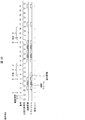
- FIG. 4 is a timing chart of image update and refresh in the display device 1 of the present embodiment. Each element in FIG. 4 represents the same meaning as in FIG. Note that a dotted rectangle in “refresh” indicates refresh in the additional drive vertical period.
- the image update timing in FIG. 4 is the same as in Reference Example 1 shown in FIG.
- the display device 1 performs refresh in each vertical period during the period in which the image is updated.
- the display device 1 does not perform refresh in each vertical period in a period when the image is not updated, except in a special case.
- the display device 1 inverts the polarity in the vertical period in which the image is not updated following the even continuous drive vertical period. Do an additional refresh. That is, when the continuous drive vertical period is an even number, one additional drive vertical period is added to make the continuous drive vertical period odd.
- the third to fourth vertical periods are periods in which the image is updated, they are even consecutive drive vertical periods.
- the image is not updated in the first to second vertical periods and the fifth to seventh vertical periods before and after that.
- the display device 1 performs additional refresh in a vertical period (fifth vertical period) in which an image update is not performed following an even consecutive driving vertical period (third to fourth vertical periods).
- a vertical period in which additional refresh is performed is referred to as an additional drive vertical period.
- the image data (data written to the pixels) used in the additional drive vertical period (fifth vertical period) is the same as the image data used in the immediately preceding drive vertical period (fourth vertical period).
- the additional drive vertical period (fifth vertical period)
- the displayed image does not change, but the pixel polarity is inverted.
- the tenth vertical period and the eighteenth vertical period following the even-numbered consecutive drive vertical periods are also set as additional drive vertical periods.
- the display device 1 of the present embodiment can prevent the pixel polarity from being biased to one side over a long period. Thereby, the display apparatus 1 can prevent a user from visually recognizing flicker, and can reduce power consumption by providing a pause vertical period.
- FIG. 5 is a flowchart showing a display control flow of the display control unit 30. A specific display control flow of each block of the display control unit 30 will be described along the operation example 1.
- the update determination unit 36 of the refresh control unit 34 sets the vertical period as the drive vertical period when the vertical period of interest (current vertical period) is included in the period in which the image is updated (Yes in step S1). (S2).
- the update determination unit 36 temporarily suspends the vertical period.
- the vertical period is set (S3).
- the polarity determination unit 35 determines the polarity (first polarity) of the drive vertical period B (second vertical period) immediately before the period A during which no image is updated, and the immediate rest vertical period before the drive vertical period B. It is determined whether or not the polarity (second polarity) of C (third vertical period) is the same (S4).
- the drive vertical period B is the latest drive vertical period (including the additional drive vertical period) before the target vertical period (resting vertical period).
- the pause vertical period C is a pause vertical period immediately before a plurality of consecutive drive vertical periods (including the drive vertical period B).
- the resting vertical period is the resting vertical period C.
- the polarity is the same from the rest vertical period C to at least the previous drive vertical period. If the second polarity in the pause vertical period C and the first polarity in the drive vertical period B are the same, the polarity is not reversed in the period A in which the image is not updated after the drive vertical period B.
- the polarity may be biased to one side.
- the polarity determination unit 35 can determine that the first polarity and the second polarity are the same if the continuous drive vertical period is an even number.
- the polarity determination unit 35 can determine that the first polarity and the second polarity are different if the continuous drive vertical period is an odd number.
- the polarity determination unit 35 may store information indicating whether the predetermined number of vertical periods in the past are drive vertical periods (including additional drive vertical periods) or pause vertical periods. .
- the polarity determination unit 35 may store the number of continuous drive vertical periods.
- the polarity determination unit 35 may store information on whether the continuous drive vertical period is an even number or an odd number.
- the additional determination unit 37 of the refresh control unit 34 determines the vertical period of interest (not updated) ( The fifth vertical period) is set as an additional drive vertical period (S5).
- the TG 33 reads the image data from the memory 32, and uses the image data as a source driver for refresh. To 21.
- the source driver 21 reverses the polarity from the previous drive vertical period and supplies the data signal to the pixels of the display unit 10, that is, the display drive unit 20 refreshes the display unit 10 (S7).
- the additional determination unit 37 of the refresh control unit 34 selects the vertical period of interest that is not updated. Then, it is set to the pause vertical period (S6).
- the pause vertical period is set, the provisional process of S3 can be omitted.
- the TG 33 does not output image data to the source driver 21.
- the display drive unit 20 does not refresh the display unit 10 (S8).
- the source driver 21 performs refresh (write to the pixel) with a polarity ( ⁇ ) different from the first polarity and the second polarity (+). Therefore, the polarity can be made different between the period before the pause vertical period C and the period after the target vertical period (fifth vertical period). Thereby, when it sees for a long term, the period when a polarity is biased can be shortened.
- the first (first) vertical period (fifth vertical period) of the period A in which image updating is not performed immediately after consecutive even drive vertical periods is defined as the additional drive vertical period.
- the present invention is not limited to this.
- a vertical period obtained by sandwiching a predetermined number of pause vertical periods from an even number of consecutive drive vertical periods may be set as the additional drive vertical period.
- the period when the image is not updated is long, even if several pause vertical periods are sandwiched between an even number of consecutive drive vertical periods and subsequent additional drive vertical periods, the polarity is biased when viewed in the long term
- the period can be shortened. It is preferable that the number of pause vertical periods provided between consecutive even drive vertical periods and subsequent additional drive vertical periods is 0 or more and 4 or less.
- a plurality of additional drive vertical periods may be provided.
- an odd number of additional drive vertical periods may be provided in period A during which no image is updated.
- the number of additional drive vertical periods is preferably 1 or 3.
- a pause vertical period may or may not be sandwiched between a plurality of odd number of additional drive vertical periods.
- Some vertical periods after the drive vertical period B are set as additional drive vertical periods.
- refreshing with image update is performed in the vertical period as usual. Good. That is, the setting of the additional drive vertical period may be canceled.
- Embodiment 2 The present embodiment is different from the first embodiment in that, in addition to the determination of the polarity, it is determined whether or not to add an additional vertical period according to the refresh rate.
- FIG. 6 is a block diagram showing the configuration of the display device 2 of the present embodiment.
- the display device 2 includes a display unit 10, a display drive unit 20, a display control unit 30a, and a host control unit 40.
- the configurations of the display drive unit 20 and the host control unit 40 are the same as those in the first embodiment.
- the display control unit 30a includes an image processing unit 31, a memory 32, a TG 33, a refresh control unit 34, a polarity determination unit 35, and a refresh rate determination unit 38.
- the configurations of the image processing unit 31, the memory 32, the TG 33, and the polarity determination unit 35 are the same as those in the first embodiment.
- the refresh rate determination unit 38 specifies the refresh rate according to whether each of the past plurality of vertical periods is a drive vertical period (including an additional drive vertical period) or a pause vertical period. The refresh rate determination unit 38 determines whether or not the specified refresh rate is less than a predetermined value. The refresh rate determination unit 38 notifies the refresh control unit 34 of the determination result.
- the addition determination unit 37 of the refresh control unit 34 does not provide an additional drive vertical period regardless of the determination result of the polarity determination unit 35 when the refresh rate is equal to or higher than the predetermined value.
- the additional determination unit 37 has a polarity different from the first polarity in a period when the image is not updated. An additional drive vertical period for performing refresh is provided.
- FIG. 7 is a timing chart of image update and refresh in the second operation example.
- Each element in FIG. 7 represents the same meaning as in FIG.
- the operation example 2 shows not the operation of the present embodiment but the same operation as the operation of the first embodiment. That is, in the operation example 2, regardless of the refresh rate, the vertical period immediately after the consecutive even number of drive vertical periods is set as the additional drive vertical period.
- the image update timing is different from that in FIG.
- the thirteenth vertical period is set as an additional drive vertical period.
- the fifteenth vertical period is also set as an additional drive vertical period.
- the seventeenth vertical period is also set as the additional drive vertical period.
- the additional drive vertical period may be provided in a chain in the subsequent period by providing the additional drive vertical period.
- the period in which the image is frequently updated (according to the refreshing) the period in which the polarity is biased to one side does not become long, so there is no need to provide an additional drive vertical period.
- the additional drive vertical period in these vertical periods there arises a new problem that unnecessary power consumption increases.
- FIG. 8 is a timing chart of image update and refresh in the display device 2 of the present embodiment. Each element in FIG. 8 represents the same meaning as in FIG.
- the image update timing in FIG. 8 is the same as that of the operation example 2 shown in FIG.
- the display device 2 performs refresh in each vertical period during the period in which the image is updated.
- the display device 2 performs additional refresh in the first vertical period in which the image update following the even consecutive drive vertical periods is not performed.
- the refresh rate is equal to or higher than the predetermined value, the display device 2 does not perform additional refresh.
- the seventh to eighth vertical periods are periods in which the image is updated, they are even consecutive driving vertical periods. Since the refresh rate in the previous predetermined period is lower than the predetermined value, the display device 2 performs additional refresh in the ninth vertical period.
- the ninth vertical period is set as an additional drive vertical period.
- the display device 2 determines that the refresh rate is lower than a predetermined value.
- the continuous pause vertical period immediately before the even continuous drive vertical period is less than 3
- the display device 2 determines that the refresh rate is equal to or higher than the predetermined value. According to this, it is possible to easily determine whether the refresh rate is high or low.
- the display device 2 determines that the refresh rate is equal to or higher than a predetermined value. Therefore, the display device 2 sets the thirteenth vertical period as the rest vertical period instead of the additional drive vertical period.
- the fourteenth and sixteenth vertical periods are odd vertical drive vertical periods. Therefore, the fifteenth and seventeenth vertical periods immediately after that are set to the pause vertical period. Also, in the twenty-first vertical period, it is determined that the refresh rate is equal to or higher than a predetermined value, and is set to the pause vertical period.
- the display device 2 of the present embodiment can suppress an increase in power consumption by not providing an additional drive vertical period during such a high refresh rate period.
- the refresh rate is low, by providing an additional drive vertical period, it is possible to prevent the pixel polarity from being biased to one over a long period. Thereby, the display device 2 can prevent flicker from being visually recognized by the user, and can reduce power consumption by appropriately providing a pause vertical period.
- FIG. 9 is a flowchart showing a display control flow of the display control unit 30a. A specific display control flow of each block of the display control unit 30a will be described along the operation example 3. Note that steps S11 to S14 and S16 to S19 shown in FIG. 9 are the same as steps S1 to S8 shown in FIG.
- the refresh rate determination unit 38 determines whether or not the refresh rate is less than a predetermined value (S15).
- the addition determination unit 37 of the refresh control unit 34 sets the target vertical period (the ninth vertical period) in which the image is not updated as the additional drive vertical period. (S16).
- the addition determination unit 37 of the refresh control unit 34 sets the target vertical period (the thirteenth vertical period) in which no image is updated as the pause vertical period. (S17).
- the refresh rate determination unit 38 determines that the refresh rate is less than a predetermined value. In other words, when the two (predetermined number) vertical periods immediately before the pause vertical period C are pause vertical periods, the refresh rate determination unit 38 determines that the refresh rate is less than the predetermined value.
- the refresh rate determination unit 38 may store how many pause vertical periods before the drive vertical period are continuous. Alternatively, the refresh rate determination unit 38 may store information on whether a plurality of past vertical periods are drive vertical periods (including additional drive vertical periods) or pause vertical periods. In this case, the refresh rate determination unit 38 can determine the refresh rate with a simple configuration and processing.
- the refresh rate determination unit 38 may obtain the previous refresh rate based on whether or not the refresh has been performed in each of a predetermined number of vertical periods (for example, about 30) immediately before the period A in which no image is updated. Good.
- the refresh rate determination unit 38 determines whether or not the obtained refresh rate is less than a predetermined value.
- the predetermined value may be set to a value (for example, 30 Hz or less) that is half or less of the vertical period rate (for example, 60 Hz), but is not limited thereto.
- the refresh rate determination unit 38 can determine the refresh rate more accurately.
- the display control unit 30 generates an interpolation frame (intermediate frame) for the moving image received from the host control unit 40, and displays the moving image by double speed driving.
- the maximum frame rate of the moving image is 60 Hz
- the maximum refresh rate of the display unit 10 is 120 Hz.
- the host control unit 40 outputs image data at a maximum of 60 Hz to the display control unit 30 only when there is an image update in the original image data.
- the image processing unit 31 When the two image update frames are continuous at 60 Hz, the image processing unit 31 generates an interpolated frame indicating an intermediate image between the previous frame and the subsequent frame. When the interval between the previous frame and the subsequent frame is long, the image processing unit 31 does not generate an interpolation frame.
- the TG 33 outputs the image data of the original frame or the image data of the interpolation frame to the display driving unit 20 at a maximum of 120 Hz. Further, the TG 33 instructs the display drive unit 20 to invert the polarity of the data signal when writing to the pixels of the original frame and not to reverse the polarity of the data signal when writing to the pixels of the interpolation frame. . This is because if polarity inversion is performed even in the interpolation frame, power consumption increases as the polarity inversion increases.
- the polarity determination unit 35 determines whether or not the first polarity and the second polarity are the same when the vertical period of interest (current vertical period) is a period in which no image update is performed.
- the first polarity is the polarity of the drive vertical period immediately before the period in which the image is not updated.
- the second polarity is the polarity of the nearest rest vertical period before the drive vertical period.
- the polarity determination unit 35 determines whether the past predetermined number of vertical periods is a driving vertical period (including an additional driving vertical period) or a resting vertical period, and information on pixels in each vertical period. The polarity may be stored.
- the addition determination unit 37 of the refresh control unit 34 performs an additional drive vertical period in which refresh is performed with a polarity different from the first polarity in the period in which the image is not updated. Is provided. Note that, when the first polarity and the second polarity are different, the refresh control unit 34 does not provide an additional drive vertical period in the period in which the image update is not performed.
- the refresh control unit 34 instructs the TG 33 whether or not to perform polarity inversion in each drive vertical period.
- the refresh control unit 34 performs polarity inversion in the drive vertical period and the additional drive vertical period in which the original frame (original image data) is written, and does not perform polarity inversion in the drive vertical period in which the interpolation frame is written. Of course, since no refresh is performed in the pause vertical period, polarity inversion is not performed.
- FIG. 10 is a timing chart of image update and refresh in the display device 1 of the present embodiment.
- Each element in FIG. 10 has the same meaning as in FIG.
- a rectangle hatched with diagonal lines in “image update” indicates that there is an image update by an interpolation frame
- a rectangle hatched with hatch lines in “refresh” indicates that an interpolation frame is written.
- a rectangle without diagonal lines indicates that original image data (frame) is written.
- a dotted rectangle in “refresh” indicates refresh in the additional drive vertical period.
- a data signal corresponding to the same image data as the image data in the immediately preceding drive vertical period is written to the pixels except for the polarity.
- 120 vertical periods are included in one second (driven at 120 Hz).
- the polarity is inverted with respect to the immediately preceding vertical period.
- the fourth vertical period in which the interpolation frame is written polarity inversion is not performed with respect to the immediately preceding vertical period.
- the third to fifth vertical periods are odd number of consecutive drive vertical periods, but the polarity (first polarity) of the drive vertical period B (fifth vertical period) immediately before the sixth vertical period and the drive vertical period B
- the polarity (second polarity) of the immediately preceding pause vertical period C (second vertical period) is the same.
- the additional determination unit 37 of the refresh control unit 34 performs the vertical period of interest (sixth vertical period) in which the image is not updated. Is set to an additional drive vertical period with polarity inversion. By providing the additional drive vertical period in this way, the polarity of the pixel is inverted before and after the continuous drive vertical period.
- the ninth to thirteenth vertical periods are consecutive odd driving vertical periods.
- the polarity (first polarity) of the drive vertical period B ′ (13th vertical period) immediately before the 14th vertical period and the polarity of the immediate rest vertical period C ′ (8th vertical period) before the drive vertical period B ( The second polarity).
- the additional determination unit 37 of the refresh control unit 34 performs the vertical period of interest (14th vertical period) in which no image is updated. Is set to the pause vertical period.
- image update is performed according to the second polarity of the pause vertical period C immediately before the continuous drive vertical period and the first polarity of the last drive vertical period B of the continuous drive vertical period.
- An additional drive vertical period accompanied by polarity inversion is provided in the period A during which no change is made.
- the display device 1 of this embodiment can prevent the polarity of the pixels from being biased to one over a long period. Thereby, the display apparatus 1 can prevent a user from visually recognizing flicker, and can reduce power consumption by providing a pause vertical period.
- the vertical period corresponding to the interpolation frame is the drive vertical period without polarity inversion, but the present invention is not limited to this.
- One embodiment of the present invention can also be applied to a case where polarity inversion is not involved in the writing of some of a plurality of original image data.
- the display device does not include a display control unit substrate, and the refresh control unit and the like are formed on the host control unit substrate.
- FIG. 11 is a block diagram showing a configuration of the display device 3 of the present embodiment.
- the display device 3 includes a display unit 10, a display driving unit 20, and a host control unit 40b.
- the configurations of the display unit 10 and the display driving unit 20 are the same as those in the first and second embodiments.
- the host control unit 40b includes a CPU 41, a host memory 42, a host TG 43, a refresh control unit 34, a refresh rate determination unit 38, and a polarity determination unit 35.
- the operations of the refresh control unit 34, the refresh rate determination unit 38, and the polarity determination unit 35 are the same as those in the second embodiment.
- the host TG 43 transfers the image data to the display driving unit 20 only when refreshing is performed corresponding to the driving vertical period (including the additional driving vertical period).
- the host TG 33 generates a timing signal for driving the display unit 10 and supplies the timing signal to the source driver 21.
- the configuration of the entire display device can be simplified.
- the display device does not include a substrate for the display control unit, and the refresh control unit and the like are provided in a display drive unit that is a COG driver.
- FIG. 12 is a block diagram showing the configuration of the display device 4 of the present embodiment.
- the display device 4 includes a display unit 10, a display drive unit 20c, and a host control unit 40.
- the configuration of the host control unit 40 is the same as that of the second embodiment. However, the host TG 43 transfers the image data to the display driving unit 20c only when the image is updated.
- the display driving unit 20c includes a memory 32, a TG 33, a refresh control unit 34, a refresh rate determination unit 38, a polarity determination unit 35, and a source driver 21.
- the operation of each part of the display driving unit 20c is the same as that of the second embodiment.
- the determination of driving or pause is performed by the COG driver (display driving unit 20c).
- the load on the host control unit 40 can be reduced without providing a separate substrate from the host control unit 40.
- the COG driver formed on the active matrix substrate has a limited mounting area, this embodiment is suitable when only a simple determination process is performed in the polarity determination unit 35 and the refresh rate determination unit 38.
- control blocks (particularly the refresh control unit 34, the polarity determination unit 35, and the refresh rate determination unit 38) of the display devices 1 to 4 are realized by a logic circuit (hardware) formed in an integrated circuit (IC chip) or the like. Alternatively, it may be realized by software using a CPU (Central Processing Unit).
- a logic circuit hardware
- IC chip integrated circuit
- CPU Central Processing Unit
- the display devices 1 to 4 include a CPU that executes instructions of a program that is software that realizes each function, and a ROM (Read Only Memory) in which the program and various data are recorded so as to be readable by a computer (or CPU) ) Or a storage device (these are referred to as “recording media”), a RAM (Random Access Memory) that expands the program, and the like.
- the objective of this invention is achieved when a computer (or CPU) reads the said program from the said recording medium and runs it.
- a “non-temporary tangible medium” such as a tape, a disk, a card, a semiconductor memory, a programmable logic circuit, or the like can be used.
- the program may be supplied to the computer via an arbitrary transmission medium (such as a communication network or a broadcast wave) that can transmit the program.
- a transmission medium such as a communication network or a broadcast wave
- the present invention can also be realized in the form of a data signal embedded in a carrier wave in which the program is embodied by electronic transmission.
- a display device is a display device in which the polarity of a data signal written to a pixel is inverted in response to refresh of the display screen, and each refresh period is refreshed in the vertical period in the image update period.
- a refresh control unit (34) that provides a vertical period during which the refresh is suspended during a period in which no image is updated, and a second period in which the refresh is performed immediately before the first period (period A) in which no image is updated.
- the polarity inversion may be performed for each refresh or only for a part of the refresh.
- the third vertical period is a pause vertical period immediately before a plurality of continuous drive vertical periods including the second vertical period.
- the second vertical period is the last driving vertical period among a plurality of consecutive driving vertical periods.
- the polarity of the pixel can be efficiently reversed, and the polarity of the pixel can be prevented from being biased to one side over a long period.
- flicker can be prevented from being visually recognized by the user, and power consumption can be reduced by providing a vertical period during which refresh is suspended.
- the display device may be configured such that, in aspect 1, the polarity of the data signal written to the pixel is inverted every time the refresh is performed.
- the first polarity and the second polarity are the same when the vertical periods in which refresh is performed continue even.
- the polarity determination unit can determine whether or not the first polarity and the second polarity are the same based on whether the vertical periods for refreshing are even-numbered or odd-numbered. Therefore, the polarity determination unit can perform the determination process with a simple configuration.
- the display device includes the refresh rate determination unit (38) that determines whether or not the refresh rate is less than a predetermined value in aspect 2, and the refresh rate is less than the predetermined value.
- the refresh control unit provides the additional vertical period in the first period, and the refresh rate is equal to or higher than the predetermined value.
- the refresh control unit may be configured not to provide the additional vertical period in the first period.
- the refresh control unit may be provided with an odd number of additional vertical periods in the first period.
- the number of vertical periods in which the refresh is provided between the second vertical period and the additional vertical period is 0 or more and 4 or less.
- the structure which is may be sufficient.
- the additional vertical period is not necessarily provided immediately after the second vertical period. However, in order to shorten the period in which the polarity is biased, the number of pause vertical periods sandwiched between the second vertical period and the additional vertical period may be four or less.
- the refresh control unit may be configured such that the first vertical period in the first period is the additional vertical period.
- the vertical period immediately after the second vertical period may be set as the additional vertical period.
- the refresh rate may be determined to be less than the predetermined value.
- the refresh rate determination unit can easily estimate the refresh rate by determining the number of continuous pause vertical periods immediately before the third period. Therefore, the configuration (resource) and processing of the refresh rate determination unit can be simplified.
- the refresh rate determination unit may determine whether the refresh has been performed in each of a predetermined number of vertical periods immediately before the first period. The refresh rate may be obtained.
- an oxide semiconductor may be used for the semiconductor layer of the TFT of the pixel.
- the oxide semiconductor may be an InGaZnO-based oxide semiconductor.
- An electronic apparatus includes the display device according to any one of the above aspects 1 to 10 and supplies image data to the display device.
- a display device control method is a display device control method in which the polarity of a data signal written to a pixel is inverted in response to refresh of a display screen, and in a period in which an image is updated, In the period in which the refresh is performed every vertical period and the image is not updated, a vertical period for suspending the refresh is provided, and the first polarity of the second vertical period in which the refresh is performed immediately before the first period in which the image is not updated, It is determined whether or not the second polarity of the third vertical period in which the refresh immediately preceding the second vertical period is paused is the same, and the first polarity and the second polarity are the same. In this case, in the first period, an additional vertical period for performing the refreshing with a polarity different from the first polarity is provided.
- the present invention can be used for a display device and an electronic device including the display device.
- Display device 10 Display unit 20, 20c Display drive unit 21 Source driver 30, 30a Display control unit 31 Image processing unit 32 Memory 33 TG 34 refresh control unit 35 polarity determination unit 36 update determination unit 37 addition determination unit 38 refresh rate determination unit 40, 40b host control unit 41 CPU 42 Host memory 43 Host TG
Landscapes
- Engineering & Computer Science (AREA)
- Physics & Mathematics (AREA)
- Computer Hardware Design (AREA)
- General Physics & Mathematics (AREA)
- Theoretical Computer Science (AREA)
- Chemical & Material Sciences (AREA)
- Crystallography & Structural Chemistry (AREA)
- Control Of Indicators Other Than Cathode Ray Tubes (AREA)
- Liquid Crystal Display Device Control (AREA)
- Liquid Crystal (AREA)
Abstract
消費電力を抑え、かつ良好な表示を行う表示装置を実現する。本発明の一態様に係る表示装置(1)は、画像更新がされない第1期間の直前の駆動垂直期間の第1極性と、該駆動垂直期間より前の直近の休止垂直期間の第2極性とが、同じであるか否かを判定する極性判定部(35)と、第1極性と第2極性とが同じである場合、第1期間において追加垂直期間を設けるリフレッシュ制御部(34)とを備える。
Description
本発明は表示装置、電子機器、および表示装置の制御方法に関する。
近年、液晶表示装置に代表される薄型、軽量、および低消費電力の表示装置が著しく普及している。こうした表示装置の典型的な搭載形態は、例えば携帯電話機、スマートフォン、ノート型PC(Personal Computer)等である。また、今後はより薄型の表示装置である電子ペーパーの開発および普及も急速に進むことが期待されている。このような状況の中、各種の表示装置において消費電力を低下させることが共通の課題となっている。
従来のCG(Continuous Grain)シリコンTFT液晶表示パネル、またはアモルファスシリコンTFT液晶表示パネル等では、60Hzで画面リフレッシュを行う必要がある。そこで、従来の液晶表示パネルの省電力化のために、60Hzより低いリフレッシュレートを実現する試みがなされている。
特許文献1には、一連のフレームに渡って画像中にストライプが存在しない場合、当該フレームがフリッカを生じやすい特徴を有しないと判断し、リフレッシュレートを低下させる液晶ディスプレイが記載されている。
特許文献2には、フレームレート変換を行う液晶ディスプレイにおいて、補間フレームが表示される場合には極性変換がされない液晶ディスプレイが記載されている。
近年、インジウム(In)、ガリウム(Ga)、亜鉛(Zn)を用いた酸化物半導体によってTFTを構成した酸化物半導体液晶表示パネルが実現されている。酸化物半導体によって構成されたTFTでは、オフ状態における電流の漏れが少ない。そのため、酸化物半導体液晶表示パネルでは、従来のように60Hzで画面リフレッシュを行う必要がなく、リフレッシュレートを1Hz程度にまで低減させることができる。そのため、酸化物半導体液晶表示パネルでは、画像更新がされない期間においてリフレッシュを休止させることができる。それゆえ、消費電力を低減することができる。
しかしながら、液晶表示パネルでは焼き付きを防止するためにリフレッシュ毎に画素の極性を反転させる交流駆動が行われる。上記のように画像更新がされない期間においてリフレッシュを休止させる場合、一定間隔でリフレッシュが行われない。そのため、動画像の画像更新のタイミングによっては、画素の極性が+極性である期間と-極性である期間とのバランスが崩れることがある。極性のバランスが崩れると、それがフリッカとして利用者に視認される可能性がある。特許文献1、2においては、上記問題は想定されていない。
本発明の一態様によれば、消費電力を抑え、かつ良好な表示を行う表示装置を実現することができる。
本発明の一態様に係る表示装置は、表示画面のリフレッシュに応じて画素に書き込まれるデータ信号の極性が反転される表示装置であって、画像更新がされる期間における各垂直期間を、上記リフレッシュを行う垂直期間とし、画像更新がされない期間において、上記リフレッシュを休止する垂直期間を設けるリフレッシュ制御部と、画像更新がされない第1期間の直前の上記リフレッシュを行う第2垂直期間の第1極性と、上記第2垂直期間より前の直近の上記リフレッシュを休止する第3垂直期間の第2極性とが、同じであるか否かを判定する極性判定部とを備え、上記第1極性と上記第2極性とが同じである場合、上記リフレッシュ制御部は、上記第1期間において、上記第1極性とは異なる極性で上記リフレッシュを行う追加垂直期間を設けることを特徴としている。
本発明の一態様に係る表示装置の制御方法は、表示画面のリフレッシュに応じて画素に書き込まれるデータ信号の極性が反転される表示装置の制御方法であって、画像更新がされる期間において、垂直期間毎に上記リフレッシュを行い、画像更新がされない期間において、上記リフレッシュを休止する垂直期間を設け、画像更新がされない第1期間の直前の上記リフレッシュを行う第2垂直期間の第1極性と、上記第2垂直期間より前の直近の上記リフレッシュを休止する第3垂直期間の第2極性とが、同じであるか否かを判定し、上記第1極性と上記第2極性とが同じである場合、上記第1期間において、上記第1極性とは異なる極性で上記リフレッシュを行う追加垂直期間を設けることを特徴としている。
本発明の一態様によれば、画素の極性が長い期間に渡って一方に偏ることを防ぐことにより、利用者にフリッカが視認されることを防ぐことができる。それゆえ、表示品位を維持し、かつ、リフレッシュを休止する垂直期間を設けることにより消費電力を低減することができる。
以下、本発明の実施形態について、詳細に説明する。以下の特定の項目(実施形態)における構成について、それが他の項目で説明されている構成と同じである場合は、説明を省略する場合がある。また、説明の便宜上、各項目に示した部材と同一の機能を有する部材については、同一の符号を付し、適宜その説明を省略する。
〔実施形態1〕
(表示装置1の構成)
図1は、本実施形態の表示装置1の構成を示すブロック図である。表示装置1は、表示部10と、表示駆動部20と、表示制御部30と、ホスト制御部40とを備えている。表示装置1は液晶表示装置である。なお、本発明は液晶表示装置に限定されず、極性反転を行う表示装置に適用することができる。
(表示装置1の構成)
図1は、本実施形態の表示装置1の構成を示すブロック図である。表示装置1は、表示部10と、表示駆動部20と、表示制御部30と、ホスト制御部40とを備えている。表示装置1は液晶表示装置である。なお、本発明は液晶表示装置に限定されず、極性反転を行う表示装置に適用することができる。
表示駆動部20は、表示部10のガラス基板にCOG(Chip on Glass)実装された、COGドライバであり、表示部10の駆動を行う。ホスト制御部40は、基板上に形成された制御回路で構成される制御基板であり、表示装置1のホスト側の制御(電子機器のための制御)を主に担う。表示制御部30は、表示する画像に対する画像処理等のために、ホスト制御部40とは別に設けられる制御基板である。本実施形態では、各垂直期間においてリフレッシュ(画素への書き込み)を行うか否かの決定を、表示制御部30で行う。これにより、ホスト制御部40の負荷を減らし、ホスト制御部40に表示以外の別の処理(例えば電子機器のアプリケーションの処理)を行わせるための処理能力を確保することができる。以下に各部の詳細な構成について説明する。
表示装置1は、画像更新の有無に応じて不要なリフレッシュを省略する、すなわちリフレッシュレートが変化する表示装置である。
(表示部10の構成)
表示部10は複数の画素を有する表示画面を備えており、例えば、アクティブマトリクス型液晶表示パネルとしての酸化物半導体液晶表示パネルによって構成されている。酸化物半導体液晶表示パネルとは、二次元的に配列された複数の画素の少なくとも1つ毎に対応して設けられたスイッチング素子に、酸化物半導体-TFT(thin film transistor)を採用した液晶表示パネルである。酸化物半導体-TFTは、半導体層に酸化物半導体が用いられたTFTである。酸化物半導体としては、例えば、インジウム・ガリウム・亜鉛の酸化物を用いた酸化物半導体(InGaZnO系酸化物半導体)がある。酸化物半導体-TFTは、オン状態において流れる電流が大きく、オフ状態におけるリーク電流が小さい。そのため、スイッチング素子に、酸化物半導体-TFTを採用したことにより、画素開口率を向上させることができる上に、画面表示のリフレッシュレートを1Hz程度にまで低減させることができる。リフレッシュレートの低減は、省電力効果をもたらす。なお、画素開口率の向上は、表示を明るくする効果、または表示の明るさをCG(ContinuousGrain)シリコン液晶表示パネルなどと同じにする場合には、バックライトの光量を下げることによる省電力効果をもたらす。
表示部10は複数の画素を有する表示画面を備えており、例えば、アクティブマトリクス型液晶表示パネルとしての酸化物半導体液晶表示パネルによって構成されている。酸化物半導体液晶表示パネルとは、二次元的に配列された複数の画素の少なくとも1つ毎に対応して設けられたスイッチング素子に、酸化物半導体-TFT(thin film transistor)を採用した液晶表示パネルである。酸化物半導体-TFTは、半導体層に酸化物半導体が用いられたTFTである。酸化物半導体としては、例えば、インジウム・ガリウム・亜鉛の酸化物を用いた酸化物半導体(InGaZnO系酸化物半導体)がある。酸化物半導体-TFTは、オン状態において流れる電流が大きく、オフ状態におけるリーク電流が小さい。そのため、スイッチング素子に、酸化物半導体-TFTを採用したことにより、画素開口率を向上させることができる上に、画面表示のリフレッシュレートを1Hz程度にまで低減させることができる。リフレッシュレートの低減は、省電力効果をもたらす。なお、画素開口率の向上は、表示を明るくする効果、または表示の明るさをCG(ContinuousGrain)シリコン液晶表示パネルなどと同じにする場合には、バックライトの光量を下げることによる省電力効果をもたらす。
(ホスト制御部40の構成)
ホスト制御部40は、CPU41(central processing unit)、ホストメモリ42、およびホストTG43(ホストタイミングジェネレータ)を備えている。
ホスト制御部40は、CPU41(central processing unit)、ホストメモリ42、およびホストTG43(ホストタイミングジェネレータ)を備えている。
CPU41は、表示画面に表示するための画像データを受け取る。また、CPU41は、画像データを表示するタイミングを示す画像更新フラグ(タイムリファレンス)を受け取る。画像データおよび画像更新フラグは、例えば表示装置1内で起動され実行中のアプリケーションによって生成される。あるいは、画像データおよび画像更新フラグは、インターネットを介したデータストリーミングまたは放送波に含まれる。ここでは、画像データは、動画像の中の1つのフレームの画像を表すデータである。
CPU41は、受け取った画像データをホストメモリ42に書き込む。CPUは、画像更新フラグに基づいて、画像更新を行うタイミングをホストTG43に指示する。なお、CPU41が、アプリケーション等の指示に基づいて、表示する画像データを生成してもよい。
ホストメモリ42は、VRAM(Video Random Access Memory)等で構成される記憶装置である。
ホストTG43は、CPU41から画像更新の指示を受け取ると、ホストメモリ42から画像データを取得し、表示制御部30に画像データを転送する。ホストTG43は、表示される画像の更新が必要な時のみ(すなわち画像の内容が変化するときのみ)、更新されるフレームの画像データを表示制御部30に転送する。画像データの転送は、例えばMIPI(ミピ:Mobile Industry Processor Interface)等のモバイル機器のデータ通信仕様に従って行われる。なお、ホストTG43は、画像データと共に同期信号を表示制御部30に転送する。
(表示制御部30の構成)
表示制御部30は、画像処理部31、メモリ32、TG33(タイミングジェネレータ)、リフレッシュ制御部34、および極性判定部35を備える。
表示制御部30は、画像処理部31、メモリ32、TG33(タイミングジェネレータ)、リフレッシュ制御部34、および極性判定部35を備える。
画像処理部31は、ホスト制御部40から受け取った画像データに対して、色彩調整等の画像処理を行う。画像処理部31は、画像処理された画像データをメモリ32に書き込む。画像処理部31は、ホスト制御部40から画像データを受け取ると、画像更新がされることをリフレッシュ制御部34に伝える。
メモリ32は、次に画像データが上書き(更新)されるまで、書き込まれた画像データを格納しておく。
リフレッシュ制御部34は、各垂直期間について、表示画面のリフレッシュを行うか否かを決定する。すなわち、リフレッシュ制御部34は、各垂直期間について、表示部10の複数の画素へのデータ信号の書き込みを行うか否かを決定する。リフレッシュ制御部34は、更新判定部36および追加判定部37を備える。
リフレッシュ制御部34の更新判定部36は、画像更新が行われる(表示される画像の内容が変化する)期間に含まれる各垂直期間を、リフレッシュを行う駆動垂直期間に設定する。更新判定部36は、画像更新が行われない期間に含まれる各垂直期間を、暫定的に、リフレッシュを休止する休止垂直期間に設定する。なお、画像更新が行われるか否かは、画像データを受け取ったか否かに基づいて判断する、または、ホスト制御部40の画像更新有り無しの通知に基づいて判断することができる。
極性判定部35は、注目対象の垂直期間(現在の垂直期間)が画像更新が行われない期間である場合、リフレッシュ制御部34が設定した過去の駆動垂直期間および休止垂直期間に基づき、第1極性と第2極性とが同じであるか否かを判定する。ここで、第1極性は、画像更新が行われない該期間の直前の駆動垂直期間の極性である。第2極性は、該駆動垂直期間の前の直近の休止垂直期間の極性である。例えば、駆動垂直期間が複数連続する場合は、第2極性は、連続する複数の駆動垂直期間の直前の休止垂直期間の極性である。極性判定部35の詳細な処理については後述する。極性判定部35は、判定結果をリフレッシュ制御部34の追加判定部37に通知する。
リフレッシュ制御部34の追加判定部37は、第1極性と第2極性とが同じである場合、画像更新が行われない該期間において、第1極性とは異なる極性でリフレッシュを行う追加駆動垂直期間(追加垂直期間)を設ける。例えば、追加判定部37は、画像更新が行われない期間における最初の垂直期間(駆動垂直期間に続く注目対象の休止垂直期間)を、リフレッシュを行う追加駆動垂直期間に設定する。なお、リフレッシュ制御部34は、第1極性と第2極性とが異なる場合、画像更新が行われない該期間において、追加駆動垂直期間を設けない。
リフレッシュ制御部34は、設定した駆動垂直期間、追加駆動垂直期間および休止垂直期間に基づいて、各垂直期間においてリフレッシュを行うか否かをTG33に通知する。
TG33は、リフレッシュ制御部34の駆動垂直期間(追加駆動垂直期間を含む)および休止垂直期間の設定に基づいて、表示部10のリフレッシュのタイミング(垂直期間のタイミング)に合わせて、画像データを表示駆動部20に転送する。TG33は、リフレッシュを行う駆動垂直期間においては、メモリ32から画像データを読み出し、画像データを表示駆動部20に転送する。一方、TG33は、リフレッシュを行わない休止垂直期間においては、画像データを表示駆動部20に転送しない。また、TG33は、表示部10を駆動するためのタイミング信号を生成し、該タイミング信号をソースドライバ21に供給する。なお、TG33は、タイミング信号を生成するためにホストTG43から入力される同期信号を利用してもよい。
なお、画像が更新されない期間が長く(例えば0.25秒以上)続く場合、リフレッシュ制御部34は、画素に書き込まれたデータ信号をリフレッシュするために、所定期間(例えば0.25秒以上)毎に駆動垂直期間を設定してもよい。これは、静止画を長時間表示する場合の表示品位を維持するためである。
(表示駆動部20の構成)
表示駆動部20は、ソースドライバ21を備える。ソースドライバ21は、タイミング信号に従って、表示部10の画素に、画像データに対応したデータ信号を書き込む。なお、本実施形態では、ソースドライバ21は、リフレッシュを行う毎に画素に書き込まれるデータ信号の極性を反転させる。ここで、データ信号(データ電位)の極性は、画素電極に対向する対向電極の電位を基準とした極性である。反転駆動の方式は特に限定されず、例えばフレーム反転駆動方式、カラム反転駆動方式、行ライン反転駆動方式、またはドット反転駆動方式であってもよい。
表示駆動部20は、ソースドライバ21を備える。ソースドライバ21は、タイミング信号に従って、表示部10の画素に、画像データに対応したデータ信号を書き込む。なお、本実施形態では、ソースドライバ21は、リフレッシュを行う毎に画素に書き込まれるデータ信号の極性を反転させる。ここで、データ信号(データ電位)の極性は、画素電極に対向する対向電極の電位を基準とした極性である。反転駆動の方式は特に限定されず、例えばフレーム反転駆動方式、カラム反転駆動方式、行ライン反転駆動方式、またはドット反転駆動方式であってもよい。
なお、表示装置1を備えるホストである電子機器の好適な例として、例えば、携帯電話機、スマートフォン、ノート型PC(personal computer)、タブレット端末、電子書籍リーダー、またはPDA(Personal Digital Assistant)等、特に携行性を重視する(電池を電源とする)電子機器を挙げることができる。
(参考例1)
図2は、比較のための参考例1における画像更新およびリフレッシュのタイミングチャートである。図2において横軸は時間である。図2において、垂直同期信号は各垂直期間を規定する信号であり、ここでは各垂直期間に便宜的に番号を付す。図2において、「画像更新」または「リフレッシュ」の矩形は、当該垂直期間において画像更新またはリフレッシュが有ることを示し、「極性」は当該垂直期間における画素の極性(画素に書き込まれているデータ信号の極性)を示す。
図2は、比較のための参考例1における画像更新およびリフレッシュのタイミングチャートである。図2において横軸は時間である。図2において、垂直同期信号は各垂直期間を規定する信号であり、ここでは各垂直期間に便宜的に番号を付す。図2において、「画像更新」または「リフレッシュ」の矩形は、当該垂直期間において画像更新またはリフレッシュが有ることを示し、「極性」は当該垂直期間における画素の極性(画素に書き込まれているデータ信号の極性)を示す。
参考例1の表示装置においては、画像更新が行われる垂直期間のみリフレッシュ(画素へのデータ信号書き込み)が行われ、画像更新が行われない垂直期間ではリフレッシュは行われない。これにより、画像更新が行われない期間の消費電力を低減することができる。また、参考例1では、リフレッシュが行われる毎に画素に書き込まれるデータ信号の極性が反転される。
例えば第1~第2垂直期間(番号が1、2の垂直期間)は、画像更新およびリフレッシュが行われない期間であり、画素の極性は+のまま変化しない。第3垂直期間において、画像更新およびリフレッシュが行われ、画素の極性が-に反転される。続く第4垂直期間においても、画像更新およびリフレッシュが行われ、画素の極性が+に反転される。第5~第7垂直期間は、画像更新およびリフレッシュが行われない期間であり、画素の極性は+のまま変化しない。第8~第9垂直期間においても、極性の反転が2回行われるので、その前後で画素の極性は変化しない。
このように、極性を反転するリフレッシュを行う駆動垂直期間が偶数連続する場合、連続する偶数の駆動垂直期間の前後で、極性が同じ(+)になってしまう。第13垂直期間のように、連続する駆動垂直期間が奇数(1つの場合を含む)の場合、連続する駆動垂直期間の前後で、極性が反転する。連続する偶数の駆動垂直期間の前後では極性が変わらないので、例えば連続する偶数の駆動垂直期間と休止垂直期間とからなる、第1垂直期間から第12垂直期間の間では、平均的に見て画素の極性が+に偏っている。また、極性が-に反転した第13垂直期間以降では、平均的に見て画素の極性が-に偏っている。例えば画像更新されない期間がもっと長く続く場合、極性が一方に偏った期間がさらに長くなる。また、連続する駆動垂直期間の数が、長期間(数秒)に渡って常に偶数である場合、長期間に渡って極性が一方に偏ってしまう。
+極性と-極性とが比較的短い期間で反転する場合、極性の反転によるフリッカは利用者には視認されない。しかしながら、極性が一方に偏った期間がある程度長くなると、極性が他方に変化したときに(図2における第13垂直期間以降に)、フリッカが利用者に視認され得る。また、各極性の周期が異なると、さらにフリッカが利用者に視認されやすい。リフレッシュを行わない休止垂直期間を画像更新の有無に応じて設ける表示装置では、画像更新が偶数回続く場合に、上記フリッカが視認されるという問題が生じ得る。画像更新のタイミングは表示される動画像に応じて異なる。
(参考例2)
図3は、比較のための参考例2における画像更新およびリフレッシュのタイミングチャートである。図3における各要素は、図2と同じ意味を表す。図3に示す参考例2と図2に示す参考例1とは画像更新のタイミングが異なる。
図3は、比較のための参考例2における画像更新およびリフレッシュのタイミングチャートである。図3における各要素は、図2と同じ意味を表す。図3に示す参考例2と図2に示す参考例1とは画像更新のタイミングが異なる。
例えば、参考例2のように画像更新がされる場合、画像更新のタイミングで極性も反転するので、一方の極性に偏った期間は参考例1に比べて短くなる。それゆえ、参考例2の場合、フリッカは利用者に視認されにくい。
(動作例1)
本実施形態では、上記フリッカが視認される問題を解決するために、画像更新がされない期間において、追加のリフレッシュを行う。以下に本実施形態における表示装置1の動作について説明する。
本実施形態では、上記フリッカが視認される問題を解決するために、画像更新がされない期間において、追加のリフレッシュを行う。以下に本実施形態における表示装置1の動作について説明する。
図4は、本実施形態の表示装置1における画像更新およびリフレッシュのタイミングチャートである。図4における各要素は、図2と同じ意味を表す。なお「リフレッシュ」における点線の矩形は、追加駆動垂直期間のリフレッシュを示す。図4における画像更新のタイミングは図2に示す参考例1と同じである。
表示装置1は、画像更新がされる期間においては、各垂直期間においてリフレッシュを行う。表示装置1は、画像更新がされない期間においては、特別な場合を除き、各垂直期間においてリフレッシュを行わない。ただし、表示装置1は、画像更新がされない期間の前に極性を反転するリフレッシュを行う駆動垂直期間が偶数連続する場合、偶数連続する駆動垂直期間に続く画像更新がされない垂直期間において、極性を反転する追加のリフレッシュを行う。すなわち、連続する駆動垂直期間が偶数の場合、追加の駆動垂直期間を1つ足して、連続する駆動垂直期間を奇数にする。
具体的には、第3~第4垂直期間は、画像更新がされる期間であるので、偶数連続する駆動垂直期間となる。その前後の第1~第2垂直期間および第5~第7垂直期間においては、画像更新がされない。表示装置1は、偶数連続する駆動垂直期間(第3~第4垂直期間)に続く画像更新がされない垂直期間(第5垂直期間)において、追加のリフレッシュを行う。ここでは、追加のリフレッシュを行う垂直期間を追加駆動垂直期間と呼ぶ。追加駆動垂直期間(第5垂直期間)において用いられる画像データ(画素に書き込まれるデータ)は、その直前の駆動垂直期間(第4垂直期間)において用いられる画像データと同じである。すなわち、追加駆動垂直期間(第5垂直期間)においては、表示される画像は変化しないが、画素の極性が反転される。偶数連続する駆動垂直期間に続く第10垂直期間および第18垂直期間も、同様に追加駆動垂直期間に設定される。このように追加駆動垂直期間を設けることにより、連続する駆動垂直期間(第3~第5垂直期間)の前後で画素の極性が反転される。図4に示すように、第1垂直期間から第21垂直期間では、画像更新の前後で極性が反転している。
そのため、本実施形態の表示装置1は、画素の極性が長い期間に渡って一方に偏ることを防ぐことができる。これにより、表示装置1は、利用者にフリッカが視認されることを防ぐことができ、かつ、休止垂直期間を設けることにより消費電力を低減することができる。
(表示制御フロー)
図5は、表示制御部30の表示制御フローを示すフローチャートである。動作例1に沿って、表示制御部30の各ブロックの具体的な表示制御フローについて説明する。
図5は、表示制御部30の表示制御フローを示すフローチャートである。動作例1に沿って、表示制御部30の各ブロックの具体的な表示制御フローについて説明する。
リフレッシュ制御部34の更新判定部36は、注目対象の垂直期間(現在の垂直期間)が画像更新がされる期間に含まれる場合(ステップS1でYes)、当該垂直期間を駆動垂直期間に設定する(S2)。
一方、更新判定部36は、注目対象の垂直期間(例えば第5垂直期間)が画像更新がされない期間A(第1期間)に含まれる場合(S1でNo)、暫定的に当該垂直期間を休止垂直期間に設定する(S3)。
S3の後、極性判定部35は、画像更新がされない期間Aの直前の駆動垂直期間B(第2垂直期間)の極性(第1極性)と、駆動垂直期間Bの前の直近の休止垂直期間C(第3垂直期間)の極性(第2極性)とが同じであるか否かを判定する(S4)。ここで、駆動垂直期間Bは、注目対象の垂直期間(休止垂直期間)の前の直近の駆動垂直期間(追加駆動垂直期間を含む)である。駆動垂直期間Bの前に他の駆動垂直期間が連続する場合、休止垂直期間Cは、連続する複数の駆動垂直期間(駆動垂直期間B含む)の直前の休止垂直期間である。駆動垂直期間Bの直前が休止垂直期間である場合、該休止垂直期間が休止垂直期間Cである。休止垂直期間Cから少なくともその前の直近の駆動垂直期間までは、極性は同じである。そして、休止垂直期間Cの第2極性と駆動垂直期間Bの第1極性とが同じである場合、駆動垂直期間Bの後の画像更新がされない期間Aにおいて極性を反転させないと、長い期間に渡って極性が一方に偏る可能性がある。
なお、リフレッシュ毎に極性が反転される場合、極性判定部35は、連続している駆動垂直期間が偶数であれば、第1極性と第2極性が同じであると判定することができる。また、極性判定部35は、連続している駆動垂直期間が奇数であれば、第1極性と第2極性が異なると判定することができる。上記判定を行うために、極性判定部35は、過去の所定数の垂直期間が駆動垂直期間(追加駆動垂直期間含む)であるか休止垂直期間であるかの情報を記憶しておいてもよい。または、上記判定を行うために、極性判定部35は、連続する駆動垂直期間の数を記憶しておいてもよい。または、上記判定をより簡単に行うために、極性判定部35は、連続する駆動垂直期間が偶数であるか奇数であるかの情報を記憶しておいてもよい。
駆動垂直期間Bの第1極性と休止垂直期間Cの第2極性とが同じである場合(S4でYes)、リフレッシュ制御部34の追加判定部37は、画像更新がされない注目対象の垂直期間(第5垂直期間)を、追加駆動垂直期間に設定する(S5)。
S2またはS5の後、注目対象の垂直期間は駆動垂直期間(追加駆動垂直期間を含む)に設定されているので、TG33は、メモリ32から画像データを読み出し、リフレッシュのために画像データをソースドライバ21に出力する。ソースドライバ21は、直前の駆動垂直期間から極性を反転させて、データ信号を表示部10の画素に供給する、すなわち表示駆動部20は表示部10のリフレッシュを行う(S7)。
一方、駆動垂直期間Bの第1極性と休止垂直期間Cの第2極性とが異なる場合(S4でNo)、リフレッシュ制御部34の追加判定部37は、画像更新がされない注目対象の垂直期間を、休止垂直期間に設定されたままにする(S6)。ここで休止垂直期間の設定を行う場合は、S3の暫定的な処理は省略することもできる。
S6の後、注目対象の垂直期間は休止垂直期間に設定されているので、TG33は、画像データをソースドライバ21に出力しない。表示駆動部20は表示部10のリフレッシュを行わない(S8)。
追加駆動垂直期間においては、ソースドライバ21は、第1極性および第2極性(+)とは異なる極性(-)でリフレッシュ(画素への書き込み)を行う。そのため、休止垂直期間C以前の期間と、注目対象の垂直期間(第5垂直期間)以降の期間とで、極性を異ならせることができる。これにより、長期的に見た場合に極性が偏る期間を短くすることができる。
(変形例)
本実施形態の上記の動作例1では、連続する偶数の駆動垂直期間の直後の、画像更新がされない期間Aの最初(最先)の垂直期間(第5垂直期間)を、追加駆動垂直期間としたが、本発明はこれに限定されない。例えば、連続する偶数の駆動垂直期間から所定数の休止垂直期間を挟んだ垂直期間を追加駆動垂直期間としてもよい。画像更新がされない期間が長い場合、連続する偶数の駆動垂直期間とその後の追加駆動垂直期間との間にいくつかの休止垂直期間が挟まれていても、長期的に見た場合に極性が偏る期間を短くすることができる。連続する偶数の駆動垂直期間とその後の追加駆動垂直期間との間に設けられる休止垂直期間の数は、0以上4以下であることが好ましい。
本実施形態の上記の動作例1では、連続する偶数の駆動垂直期間の直後の、画像更新がされない期間Aの最初(最先)の垂直期間(第5垂直期間)を、追加駆動垂直期間としたが、本発明はこれに限定されない。例えば、連続する偶数の駆動垂直期間から所定数の休止垂直期間を挟んだ垂直期間を追加駆動垂直期間としてもよい。画像更新がされない期間が長い場合、連続する偶数の駆動垂直期間とその後の追加駆動垂直期間との間にいくつかの休止垂直期間が挟まれていても、長期的に見た場合に極性が偏る期間を短くすることができる。連続する偶数の駆動垂直期間とその後の追加駆動垂直期間との間に設けられる休止垂直期間の数は、0以上4以下であることが好ましい。
また、1つの画像更新がされない期間Aにおいて、追加駆動垂直期間は、複数設けられてもよい。すなわち、追加駆動垂直期間は、画像更新がされない期間Aにおいて奇数個設けられればよい。なお、追加駆動垂直期間の数が増えると省電力効果が低下するので、追加駆動垂直期間の数は1または3であることが好ましい。複数の奇数個の追加駆動垂直期間の間には、休止垂直期間が挟まれていてもいなくてもよい。
駆動垂直期間Bのいくつか後の垂直期間を追加駆動垂直期間に設定したが、当該垂直期間において画像更新がされることになった場合、当該垂直期間において通常通り画像更新を伴うリフレッシュを行えばよい。すなわち、追加駆動垂直期間の設定を解除すればよい。
なお、これらの変形例は、後述の実施形態においても適用することができる。
〔実施形態2〕
本実施形態では、極性の判定に加えて、リフレッシュレートに応じて、追加垂直期間を追加するか否かを判断する点が実施形態1と異なる。
本実施形態では、極性の判定に加えて、リフレッシュレートに応じて、追加垂直期間を追加するか否かを判断する点が実施形態1と異なる。
図6は、本実施形態の表示装置2の構成を示すブロック図である。表示装置2は、表示部10と、表示駆動部20と、表示制御部30aと、ホスト制御部40とを備えている。表示駆動部20およびホスト制御部40の構成は、実施形態1と同じである。
(表示制御部30aの構成)
表示制御部30aは、画像処理部31、メモリ32、TG33、リフレッシュ制御部34、極性判定部35、およびリフレッシュレート判定部38を備える。画像処理部31、メモリ32、TG33、極性判定部35の構成は、実施形態1と同じである。
表示制御部30aは、画像処理部31、メモリ32、TG33、リフレッシュ制御部34、極性判定部35、およびリフレッシュレート判定部38を備える。画像処理部31、メモリ32、TG33、極性判定部35の構成は、実施形態1と同じである。
リフレッシュレート判定部38は、過去の複数の垂直期間のそれぞれが駆動垂直期間(追加駆動垂直期間を含む)であるか休止垂直期間であるかに応じて、リフレッシュレートを特定する。リフレッシュレート判定部38は、特定されたリフレッシュレートが所定値未満であるか否かを判定する。リフレッシュレート判定部38は、判定結果をリフレッシュ制御部34に通知する。
リフレッシュ制御部34の追加判定部37は、リフレッシュレートが上記所定値以上である場合、極性判定部35の判定結果に関わらず、追加駆動垂直期間を設けない。一方、リフレッシュレートが上記所定値未満であり、かつ、第1極性と第2極性とが同じである場合、追加判定部37は、画像更新が行われない期間において、第1極性とは異なる極性でリフレッシュを行う追加駆動垂直期間を設ける。
(動作例2)
図7は、動作例2における画像更新およびリフレッシュのタイミングチャートである。図7における各要素は、図2と同じ意味を表す。動作例2は、本実施形態の動作ではなく、実施形態1の動作と同じ動作を示すものである。すなわち、動作例2では、リフレッシュレートに関わらず、連続する偶数の駆動垂直期間の直後の垂直期間を追加駆動垂直期間としている。図7では、画像更新のタイミングが図4とは異なる。
図7は、動作例2における画像更新およびリフレッシュのタイミングチャートである。図7における各要素は、図2と同じ意味を表す。動作例2は、本実施形態の動作ではなく、実施形態1の動作と同じ動作を示すものである。すなわち、動作例2では、リフレッシュレートに関わらず、連続する偶数の駆動垂直期間の直後の垂直期間を追加駆動垂直期間としている。図7では、画像更新のタイミングが図4とは異なる。
例えば第13垂直期間に注目すると、直前に偶数の駆動垂直期間(第11~第12垂直期間)が連続しているので、第13垂直期間は追加駆動垂直期間に設定される。
第15垂直期間に注目すると、第13垂直期間が追加駆動垂直期間に設定されたので、直前に偶数の駆動垂直期間(第11~第14垂直期間)が連続している。その結果、第15垂直期間も追加駆動垂直期間に設定される。
同様に、第17垂直期間の直前にも偶数の駆動垂直期間(第11~第16垂直期間)が連続しているので、第17垂直期間も追加駆動垂直期間に設定される。
このように、ほぼ半分の垂直期間で画像更新が行われる場合、追加駆動垂直期間を設けることにより、その後の期間において連鎖的に追加駆動垂直期間を設けてしまう場合がある。例えば、極性が一方に偏る期間の長さを考慮しても第13、第15、第17垂直期間に追加駆動垂直期間を設ける必要はない。頻繁に画像更新(に伴うリフレッシュ)がされている期間においては、極性が一方に偏る期間は長くならないので、追加駆動垂直期間を設ける必要はない。これらの垂直期間に追加駆動垂直期間を設けた結果、不要な消費電力が増加してしまうという新たな問題が生じる。
(動作例3)
本実施形態では、画像更新のタイミングによっては不要な消費電力が増加してしまうという問題を解決するために、リフレッシュレートに応じて、追加垂直期間を追加するか否かが判断される。以下に本実施形態における表示装置2の動作(動作例3)について説明する。
本実施形態では、画像更新のタイミングによっては不要な消費電力が増加してしまうという問題を解決するために、リフレッシュレートに応じて、追加垂直期間を追加するか否かが判断される。以下に本実施形態における表示装置2の動作(動作例3)について説明する。
図8は、本実施形態の表示装置2における画像更新およびリフレッシュのタイミングチャートである。図8における各要素は、図2と同じ意味を表す。図8における画像更新のタイミングは図7に示す動作例2と同じである。
表示装置2は、画像更新がされる期間においては、各垂直期間においてリフレッシュを行う。リフレッシュレートが所定値より低い場合、表示装置2は、偶数連続する駆動垂直期間に続く画像更新がされない最初の垂直期間において、追加のリフレッシュを行う。ただし、リフレッシュレートが所定値以上の場合、表示装置2は、追加のリフレッシュを行わない。
具体的には、第7~第8垂直期間は、画像更新がされる期間であるので、偶数連続する駆動垂直期間となる。その前の所定の期間におけるリフレッシュレートが所定値より低いので、表示装置2は第9垂直期間において追加のリフレッシュを行う。第9垂直期間は追加駆動垂直期間に設定される。ここでは、偶数連続する駆動垂直期間の直前に、3つ以上の休止垂直期間が連続している場合、表示装置2は、リフレッシュレートは所定値より低いと判断する。偶数連続する駆動垂直期間の直前に連続する休止垂直期間が3未満の場合、表示装置2は、リフレッシュレートは所定値以上であると判断する。これによれば、簡易にリフレッシュレートが高いか低いかを判定することができる。
一方、その後の偶数連続する駆動垂直期間(第11~第12垂直期間)の直前に連続する休止垂直期間は、1つ(第10垂直期間のみ)である。そのため、第13垂直期間の時点で、表示装置2は、リフレッシュレートが所定値以上であると判断する。それゆえ、表示装置2は、第13垂直期間を追加駆動垂直期間ではなく休止垂直期間に設定する。
動作例2とは異なり第13垂直期間が休止垂直期間になったので、第14、第16垂直期間は、それぞれ奇数連続する駆動垂直期間である。そのため、その直後の第15、第17垂直期間は休止垂直期間に設定される。また、第21垂直期間も、リフレッシュレートが所定値以上であると判断され、休止垂直期間に設定される。
頻繁に画像更新に伴うリフレッシュが行われる期間では、リフレッシュ毎に極性が反転するので、極性の偏りは小さい。本実施形態の表示装置2は、そのようなリフレッシュレートが高い期間では、追加駆動垂直期間を設けないことにより、消費電力の増加を抑制することができる。一方で、リフレッシュレートが低い期間では、追加駆動垂直期間を設けることにより、画素の極性が長い期間に渡って一方に偏ることを防ぐことができる。これにより、表示装置2は、利用者にフリッカが視認されることを防ぐことができ、かつ、適切に休止垂直期間を設けることにより消費電力を低減することができる。
(表示制御フロー)
図9は、表示制御部30aの表示制御フローを示すフローチャートである。動作例3に沿って、表示制御部30aの各ブロックの具体的な表示制御フローについて説明する。なお、図9に示すステップS11~S14、S16~S19は、それぞれ図5に示すステップS1~S8と同じであるので、説明を省略する。
図9は、表示制御部30aの表示制御フローを示すフローチャートである。動作例3に沿って、表示制御部30aの各ブロックの具体的な表示制御フローについて説明する。なお、図9に示すステップS11~S14、S16~S19は、それぞれ図5に示すステップS1~S8と同じであるので、説明を省略する。
駆動垂直期間B(第8、第12垂直期間)の第1極性とその前の直近の休止垂直期間C(第6、第10垂直期間)の第2極性とが同じである場合(S14でYes)、リフレッシュレート判定部38は、リフレッシュレートが所定値未満であるか否かを判定する(S15)。
リフレッシュレートが所定値未満である場合(S15でYes)、リフレッシュ制御部34の追加判定部37は、画像更新がされない注目対象の垂直期間(第9垂直期間)を、追加駆動垂直期間に設定する(S16)。
一方、リフレッシュレートが所定値以上である場合(S15でNo)、リフレッシュ制御部34の追加判定部37は、画像更新がされない注目対象の垂直期間(第13垂直期間)を、休止垂直期間に設定されたままにする(S17)。
なおS15において、リフレッシュレート判定部38は、休止垂直期間Cを含む、連続する休止垂直期間の数が3以上である場合、リフレッシュレートは所定値未満であると判定する。言い換えれば、リフレッシュレート判定部38は、休止垂直期間Cの直前の2個(所定数)の垂直期間が、休止垂直期間である場合、リフレッシュレートは所定値未満であると判定する。リフレッシュレート判定部38は、上記判定を行うために、駆動垂直期間の前の休止垂直期間が何個連続していたかを記憶しておいてもよい。あるいは、リフレッシュレート判定部38は、過去の複数の垂直期間が駆動垂直期間(追加駆動垂直期間含む)であるか休止垂直期間であるかの情報を記憶しておいてもよい。この場合、リフレッシュレート判定部38は、簡単な構成および処理によって、リフレッシュレートを判定することができる。
または、リフレッシュレート判定部38は、画像更新がされない期間Aの直前の所定数(例えば30程度)の垂直期間のそれぞれにおいてリフレッシュが行われたか否かに基づいて、直前のリフレッシュレートを求めてもよい。リフレッシュレート判定部38は、過去の所定期間(所定数の垂直期間)の各垂直期間が駆動垂直期間(追加駆動垂直期間含む)であるか休止垂直期間であるかの情報を記憶しておけばよい。該情報に基づいて、リフレッシュレート判定部38は、過去の所定期間におけるリフレッシュレート(=駆動垂直期間数/全垂直期間数)を求めることができる。リフレッシュレート判定部38は、求めたリフレッシュレートが所定値未満であるか否かを判定する。この所定値は、例えば垂直期間のレート(例えば60Hz)の半分以下の値(例えば30Hz以下)に設定してもよいが、これに限らない。この場合、リフレッシュレート判定部38は、より正確にリフレッシュレートを判定することができる。
なお、リフレッシュレートの判定(S15)および極性の判定(S14)の処理の順序は、逆であってもよい。
〔実施形態3〕
本実施形態では、極性反転を伴わないリフレッシュが存在する、すなわち、リフレッシュ毎に極性反転が行われない場合について説明する。本実施形態の表示装置の構成は、図1に示すブロック図と同じである。ただし、表示制御部30および表示駆動部20における処理が実施形態1とは異なる。
本実施形態では、極性反転を伴わないリフレッシュが存在する、すなわち、リフレッシュ毎に極性反転が行われない場合について説明する。本実施形態の表示装置の構成は、図1に示すブロック図と同じである。ただし、表示制御部30および表示駆動部20における処理が実施形態1とは異なる。
本実施形態では、表示制御部30は、ホスト制御部40から受け取った動画像に対して補間フレーム(中間フレーム)を生成し、動画像を倍速駆動で表示させる。動画像の最大のフレームレートを60Hzとした場合、表示部10の最大のリフレッシュレートは120Hzである。ホスト制御部40は、オリジナルの画像データにおいて画像更新があるときのみ、最大60Hzで画像データを表示制御部30に出力する。
画像処理部31は、2つの画像更新のフレームが60Hzで連続する場合、前のフレームと後のフレームとの中間の画像を示す、補間フレームを生成する。画像処理部31は、前のフレームと後のフレームとの間隔が長い場合、補間フレームを生成しない。
TG33は、オリジナルのフレームの画像データまたは補間フレームの画像データを、最大120Hzで表示駆動部20に出力する。また、TG33は、オリジナルのフレームの画素への書き込みにおいては、データ信号の極性を反転させ、補間フレームの画素への書き込みにおいては、データ信号の極性を反転させないよう、表示駆動部20に指示する。これは、補間フレームにおいても極性反転を行うと、極性反転の増加に伴って消費電力が増加するためである。
極性判定部35は、注目対象の垂直期間(現在の垂直期間)が画像更新が行われない期間である場合、第1極性と第2極性とが同じであるか否かを判定する。ここで、第1極性は、画像更新が行われない該期間の直前の駆動垂直期間の極性である。第2極性は、該駆動垂直期間の前の直近の休止垂直期間の極性である。上記判定を行うために、極性判定部35は、過去の所定数の垂直期間が駆動垂直期間(追加駆動垂直期間含む)であるか休止垂直期間であるかの情報、および各垂直期間における画素の極性を記憶しておいてもよい。
リフレッシュ制御部34の追加判定部37は、第1極性と第2極性とが同じである場合、画像更新が行われない該期間において、第1極性とは異なる極性でリフレッシュを行う追加駆動垂直期間を設ける。なお、リフレッシュ制御部34は、第1極性と第2極性とが異なる場合、画像更新が行われない該期間において、追加駆動垂直期間を設けない。
リフレッシュ制御部34は、各駆動垂直期間において極性反転を行うか否かをTG33に指示する。リフレッシュ制御部34は、オリジナルのフレーム(オリジナルの画像データ)を書き込む駆動垂直期間および追加駆動垂直期間では極性反転を行わせ、補間フレームを書き込む駆動垂直期間では極性反転を行わせない。もちろん休止垂直期間ではリフレッシュが行われないので極性反転はされない。
(動作例4)
以下に本実施形態における表示装置1の動作(動作例4)について説明する。
以下に本実施形態における表示装置1の動作(動作例4)について説明する。
図10は、本実施形態の表示装置1における画像更新およびリフレッシュのタイミングチャートである。図10における各要素は、図2と同じ意味を表す。図10において、「画像更新」における斜線でハッチングされた矩形は、補間フレームによる画像更新があることを示し、「リフレッシュ」における斜線でハッチングされた矩形は、補間フレームを書き込むことを示す。一方、斜線無しの矩形は、オリジナルの画像データ(フレーム)を書き込むことを示す。「リフレッシュ」における点線の矩形は、追加駆動垂直期間のリフレッシュを示す。追加駆動垂直期間においては、極性を除き、直前の駆動垂直期間の画像データと同じ画像データに対応するデータ信号が画素に書き込まれる。なお、図10においては、1秒間に120個の垂直期間が含まれる(120Hzで駆動される)。
オリジナルの画像データが書き込まれる第3、第5垂直期間では、直前の垂直期間に対して極性の反転が行われる。これに対し、補間フレームが書き込まれる第4垂直期間では、直前の垂直期間に対して極性の反転が行われない。なお、第3、第5垂直期間のように、オリジナルの画像データが60Hzで連続する場合、その間の第4垂直期間に補間フレームの表示が行われる。一方、第5、第9垂直期間のように、オリジナルの画像データのフレームレートが60Hz未満の期間(第6~第8垂直期間)では、補間フレームの表示は行われない。
画像更新がされない期間Aの最初の第6垂直期間に注目する。第3~第5垂直期間は連続する奇数の駆動垂直期間であるが、第6垂直期間の直前の駆動垂直期間B(第5垂直期間)の極性(第1極性)と、駆動垂直期間Bの前の直近の休止垂直期間C(第2垂直期間)の極性(第2極性)とは同じである。駆動垂直期間Bの第1極性と休止垂直期間Cの第2極性とが同じである場合、リフレッシュ制御部34の追加判定部37は、画像更新がされない注目対象の垂直期間(第6垂直期間)を、極性反転を伴う追加駆動垂直期間に設定する。このように追加駆動垂直期間を設けることにより、連続する駆動垂直期間の前後で画素の極性が反転される。
次に画像更新がされない期間A’の最初の第14垂直期間に注目する。第9~第13垂直期間は連続する奇数の駆動垂直期間である。第14垂直期間の直前の駆動垂直期間B’(第13垂直期間)の極性(第1極性)と、駆動垂直期間Bの前の直近の休止垂直期間C’(第8垂直期間)の極性(第2極性)とは異なっている。駆動垂直期間B’の第1極性と休止垂直期間C’の第2極性とが異なる場合、リフレッシュ制御部34の追加判定部37は、画像更新がされない注目対象の垂直期間(第14垂直期間)を、休止垂直期間に設定する。
このように、本実施形態では、連続する駆動垂直期間の直前の休止垂直期間Cの第2極性と、連続する駆動垂直期間の最後の駆動垂直期間Bの第1極性とに応じて、画像更新がされない期間Aにおいて極性反転を伴う追加駆動垂直期間を設ける。これにより、極性反転を伴わない駆動垂直期間(例えば第4垂直期間)が存在している場合であっても、連続する駆動垂直期間の前後で適切に極性を反転させることができる。そのため、本実施形態の表示装置1は、画素の極性が長い期間に渡って一方に偏ることを防ぐことができる。これにより、表示装置1は、利用者にフリッカが視認されることを防ぐことができ、かつ、休止垂直期間を設けることにより消費電力を低減することができる。
なお、2つのオリジナルフレームの間の補間フレームの数を1としたが、2つのオリジナルフレームの間に複数の補間フレームが生成されてもよい。
また、ここでは補間フレームに対応する垂直期間が極性反転を伴わない駆動垂直期間であるとしたが、これに限らない。本発明の一態様は、複数のオリジナルの画像データの一部の書き込みにおいて極性反転を伴わない場合にも適用可能である。
〔実施形態4〕
本実施形態では、実施形態2とは異なり、表示装置は表示制御部の基板を備えず、リフレッシュ制御部等はホスト制御部の基板上に形成される。
本実施形態では、実施形態2とは異なり、表示装置は表示制御部の基板を備えず、リフレッシュ制御部等はホスト制御部の基板上に形成される。
図11は、本実施形態の表示装置3の構成を示すブロック図である。表示装置3は、表示部10と、表示駆動部20と、ホスト制御部40bとを備えている。表示部10および表示駆動部20の構成は、実施形態1、2と同様である。
(ホスト制御部40bの構成)
ホスト制御部40bは、CPU41、ホストメモリ42、ホストTG43、リフレッシュ制御部34、リフレッシュレート判定部38、および極性判定部35を備える。リフレッシュ制御部34、リフレッシュレート判定部38、および極性判定部35の動作は、実施形態2と同様である。
ホスト制御部40bは、CPU41、ホストメモリ42、ホストTG43、リフレッシュ制御部34、リフレッシュレート判定部38、および極性判定部35を備える。リフレッシュ制御部34、リフレッシュレート判定部38、および極性判定部35の動作は、実施形態2と同様である。
ホストTG43は、駆動垂直期間(追加駆動垂直期間を含む)に対応してリフレッシュが行われるときのみ画像データを表示駆動部20に転送する。ホストTG33は、表示部10を駆動するためのタイミング信号を生成し、該タイミング信号をソースドライバ21に供給する。
このように表示制御部の基板を省略し、ホスト制御部40bに追加駆動垂直期間を設ける判定を行わせることで、表示装置全体の構成を簡略化することもできる。
〔実施形態5〕
本実施形態では、実施形態2とは異なり、表示装置は表示制御部の基板を備えず、リフレッシュ制御部等はCOGドライバである表示駆動部に設けられている。
本実施形態では、実施形態2とは異なり、表示装置は表示制御部の基板を備えず、リフレッシュ制御部等はCOGドライバである表示駆動部に設けられている。
図12は、本実施形態の表示装置4の構成を示すブロック図である。表示装置4は、表示部10と、表示駆動部20cと、ホスト制御部40とを備えている。
ホスト制御部40の構成は、実施形態2と同様である。ただし、ホストTG43は、画像更新がされるときのみ画像データを表示駆動部20cに転送する。
表示駆動部20cは、メモリ32、TG33、リフレッシュ制御部34、リフレッシュレート判定部38、極性判定部35、およびソースドライバ21を備える。表示駆動部20cの各部の動作は、実施形態2と同様である。
本実施形態では、駆動または休止の判定を、COGドライバ(表示駆動部20c)で行う。これにより、ホスト制御部40とは別の基板を設けることなく、ホスト制御部40の負荷を減らすことができる。アクティブマトリクス基板に形成されるCOGドライバは実装面積が制限されるため、本実施形態は、極性判定部35およびリフレッシュレート判定部38において簡単な判定処理のみを行う場合に適している。
〔ソフトウェアによる実現例〕
表示装置1~4の制御ブロック(特にリフレッシュ制御部34、極性判定部35、およびリフレッシュレート判定部38)は、集積回路(ICチップ)等に形成された論理回路(ハードウェア)によって実現してもよいし、CPU(Central Processing Unit)を用いてソフトウェアによって実現してもよい。
表示装置1~4の制御ブロック(特にリフレッシュ制御部34、極性判定部35、およびリフレッシュレート判定部38)は、集積回路(ICチップ)等に形成された論理回路(ハードウェア)によって実現してもよいし、CPU(Central Processing Unit)を用いてソフトウェアによって実現してもよい。
後者の場合、表示装置1~4は、各機能を実現するソフトウェアであるプログラムの命令を実行するCPU、上記プログラムおよび各種データがコンピュータ(またはCPU)で読み取り可能に記録されたROM(Read Only Memory)または記憶装置(これらを「記録媒体」と称する)、上記プログラムを展開するRAM(Random Access Memory)などを備えている。そして、コンピュータ(またはCPU)が上記プログラムを上記記録媒体から読み取って実行することにより、本発明の目的が達成される。上記記録媒体としては、「一時的でない有形の媒体」、例えば、テープ、ディスク、カード、半導体メモリ、プログラマブルな論理回路などを用いることができる。また、上記プログラムは、該プログラムを伝送可能な任意の伝送媒体(通信ネットワークや放送波等)を介して上記コンピュータに供給されてもよい。なお、本発明は、上記プログラムが電子的な伝送によって具現化された、搬送波に埋め込まれたデータ信号の形態でも実現され得る。
〔まとめ〕
本発明の態様1に係る表示装置は、表示画面のリフレッシュに応じて画素に書き込まれるデータ信号の極性が反転される表示装置であって、画像更新がされる期間における各垂直期間を、上記リフレッシュを行う垂直期間とし、画像更新がされない期間において、上記リフレッシュを休止する垂直期間を設けるリフレッシュ制御部(34)と、画像更新がされない第1期間(期間A)の直前の上記リフレッシュを行う第2垂直期間の第1極性と、上記第2垂直期間(垂直期間B)より前の直近の上記リフレッシュを休止する第3垂直期間(垂直期間C)の第2極性とが、同じであるか否かを判定する極性判定部(35)とを備え、上記第1極性と上記第2極性とが同じである場合、上記リフレッシュ制御部は、上記第1期間において、上記第1極性とは異なる極性で上記リフレッシュを行う追加垂直期間(追加駆動垂直期間)を設ける。
本発明の態様1に係る表示装置は、表示画面のリフレッシュに応じて画素に書き込まれるデータ信号の極性が反転される表示装置であって、画像更新がされる期間における各垂直期間を、上記リフレッシュを行う垂直期間とし、画像更新がされない期間において、上記リフレッシュを休止する垂直期間を設けるリフレッシュ制御部(34)と、画像更新がされない第1期間(期間A)の直前の上記リフレッシュを行う第2垂直期間の第1極性と、上記第2垂直期間(垂直期間B)より前の直近の上記リフレッシュを休止する第3垂直期間(垂直期間C)の第2極性とが、同じであるか否かを判定する極性判定部(35)とを備え、上記第1極性と上記第2極性とが同じである場合、上記リフレッシュ制御部は、上記第1期間において、上記第1極性とは異なる極性で上記リフレッシュを行う追加垂直期間(追加駆動垂直期間)を設ける。
ここで、極性の反転は、リフレッシュ毎に行われてもよいし、一部のリフレッシュのみにおいて行われてもよい。リフレッシュを行う複数の駆動垂直期間が連続する場合、第3垂直期間は、第2垂直期間を含む複数の連続する駆動垂直期間の直前の休止垂直期間である。また、第2垂直期間は、複数の連続する駆動垂直期間のうちの最後の駆動垂直期間である。
上記の構成によれば、効率的に画素の極性を反転させることができ、画素の極性が長い期間に渡って一方に偏ることを防ぐことができる。これにより、利用者にフリッカが視認されることを防ぐことができ、かつ、リフレッシュを休止する垂直期間を設けることにより消費電力を低減することができる。
本発明の態様2に係る表示装置は、上記態様1において、上記リフレッシュを行う毎に上記画素に書き込まれる上記データ信号の極性が反転される構成であってもよい。
上記の構成によれば、リフレッシュを行う垂直期間が偶数連続する場合、第1極性と第2極性とが同じになる。極性判定部は、リフレッシュを行う垂直期間が偶数連続するか奇数連続するかに基づいて、第1極性と第2極性とが同じであるか否かを判定することができる。それゆえ、極性判定部は、簡単な構成で判定処理を行うことができる。
本発明の態様3に係る表示装置は、上記態様2において、リフレッシュレートが所定値未満であるか否かを判定するリフレッシュレート判定部(38)を備え、上記リフレッシュレートが上記所定値未満であり、かつ、上記第1極性と上記第2極性とが同じである場合、上記リフレッシュ制御部は、上記第1期間において、上記追加垂直期間を設け、上記リフレッシュレートが上記所定値以上である場合、上記リフレッシュ制御部は、上記第1期間において、上記追加垂直期間を設けない構成であってもよい。
上記の構成によれば、リフレッシュレートが高いときに不要な極性の反転を増加させることなく、リフレッシュレートが低いときに効果的に極性を反転させる追加のリフレッシュを行うことができる。それゆえ、消費電力の抑制と、表示品位の維持を両立することができる。
本発明の態様4に係る表示装置では、上記態様1から3において、上記リフレッシュ制御部は、上記第1期間において、奇数個の上記追加垂直期間を設ける構成であってもよい。
本発明の態様5に係る表示装置では、上記態様1から4において、上記第2垂直期間と、上記追加垂直期間との間に設けられる上記リフレッシュを休止する垂直期間の数は、0以上4以下である構成であってもよい。
追加垂直期間は、必ずしも第2垂直期間の直後に設けられなくてもよい。ただし、極性が偏る期間を短くするために、第2垂直期間と追加垂直期間との間に挟まれる休止垂直期間の数は4以下としてもよい。
本発明の態様6に係る表示装置では、上記態様1から4において、上記リフレッシュ制御部は、上記第1期間における最初の垂直期間を、上記追加垂直期間とする構成であってもよい。
このように、第2垂直期間の直後の垂直期間を、追加垂直期間に設定してもよい。
本発明の態様7に係る表示装置では、上記態様3において、上記リフレッシュレート判定部は、上記第3垂直期間の直前の所定数の垂直期間が、上記リフレッシュを休止する垂直期間である場合、上記リフレッシュレートは上記所定値未満であると判定する構成であってもよい。
上記の構成によれば、第3期間の直前に連続する休止垂直期間の数を判定することで、リフレッシュレート判定部は、簡易的にリフレッシュレートを推測することができる。それゆえ、リフレッシュレート判定部の構成(リソース)および処理を簡単にすることができる。
本発明の態様8に係る表示装置では、上記態様3において、上記リフレッシュレート判定部は、上記第1期間の直前の所定数の垂直期間のそれぞれにおいて上記リフレッシュが行われたか否かに基づいて、上記リフレッシュレートを求める構成であってもよい。
上記の構成によれば、より正確なリフレッシュレートを求めることができる。そのため、追加垂直期間の要否をより適切に判定することができる。
本発明の態様9に係る表示装置では、上記態様1から8において、上記画素のTFTの半導体層には、酸化物半導体が用いられている構成であってもよい。
本発明の態様10に係る表示装置では、上記態様9において、上記酸化物半導体は、InGaZnO系酸化物半導体である構成であってもよい。
本発明の態様11に係る電子機器は、上記態様1から10のいずれかの表示装置を備え、上記表示装置に画像データを供給する構成である。
本発明の態様12に係る表示装置の制御方法は、表示画面のリフレッシュに応じて画素に書き込まれるデータ信号の極性が反転される表示装置の制御方法であって、画像更新がされる期間において、垂直期間毎に上記リフレッシュを行い、画像更新がされない期間において、上記リフレッシュを休止する垂直期間を設け、画像更新がされない第1期間の直前の上記リフレッシュを行う第2垂直期間の第1極性と、上記第2垂直期間より前の直近の上記リフレッシュを休止する第3垂直期間の第2極性とが、同じであるか否かを判定し、上記第1極性と上記第2極性とが同じである場合、上記第1期間において、上記第1極性とは異なる極性で上記リフレッシュを行う追加垂直期間を設ける。
本発明は上述した各実施形態に限定されるものではなく、請求項に示した範囲で種々の変更が可能であり、異なる実施形態にそれぞれ開示された技術的手段を適宜組み合わせて得られる実施形態についても本発明の技術的範囲に含まれる。さらに、各実施形態にそれぞれ開示された技術的手段を組み合わせることにより、新しい技術的特徴を形成することができる。
本発明は、表示装置および表示装置を備える電子機器に利用することができる。
1~4 表示装置
10 表示部
20、20c 表示駆動部
21 ソースドライバ
30、30a 表示制御部
31 画像処理部
32 メモリ
33 TG
34 リフレッシュ制御部
35 極性判定部
36 更新判定部
37 追加判定部
38 リフレッシュレート判定部
40、40b ホスト制御部
41 CPU
42 ホストメモリ
43 ホストTG
10 表示部
20、20c 表示駆動部
21 ソースドライバ
30、30a 表示制御部
31 画像処理部
32 メモリ
33 TG
34 リフレッシュ制御部
35 極性判定部
36 更新判定部
37 追加判定部
38 リフレッシュレート判定部
40、40b ホスト制御部
41 CPU
42 ホストメモリ
43 ホストTG
Claims (12)
- 表示画面のリフレッシュに応じて画素に書き込まれるデータ信号の極性が反転される表示装置であって、
画像更新がされる期間における各垂直期間を、上記リフレッシュを行う垂直期間とし、画像更新がされない期間において、上記リフレッシュを休止する垂直期間を設けるリフレッシュ制御部と、
画像更新がされない第1期間の直前の上記リフレッシュを行う第2垂直期間の第1極性と、上記第2垂直期間より前の直近の上記リフレッシュを休止する第3垂直期間の第2極性とが、同じであるか否かを判定する極性判定部とを備え、
上記第1極性と上記第2極性とが同じである場合、上記リフレッシュ制御部は、上記第1期間において、上記第1極性とは異なる極性で上記リフレッシュを行う追加垂直期間を設けることを特徴とする表示装置。 - 上記リフレッシュを行う毎に上記画素に書き込まれる上記データ信号の極性が反転されることを特徴とする請求項1に記載の表示装置。
- リフレッシュレートが所定値未満であるか否かを判定するリフレッシュレート判定部を備え、
上記リフレッシュレートが上記所定値未満であり、かつ、上記第1極性と上記第2極性とが同じである場合、上記リフレッシュ制御部は、上記第1期間において、上記追加垂直期間を設け、
上記リフレッシュレートが上記所定値以上である場合、上記リフレッシュ制御部は、上記第1期間において、上記追加垂直期間を設けないことを特徴とする請求項2に記載の表示装置。 - 上記リフレッシュ制御部は、上記第1期間において、奇数個の上記追加垂直期間を設けることを特徴とする請求項1から3のいずれか一項に記載の表示装置。
- 上記第2垂直期間と、上記追加垂直期間との間に設けられる上記リフレッシュを休止する垂直期間の数は、0以上4以下であることを特徴とする請求項1から4のいずれか一項に記載の表示装置。
- 上記リフレッシュ制御部は、上記第1期間における最初の垂直期間を、上記追加垂直期間とすることを特徴とする請求項1から4のいずれか一項に記載の表示装置。
- 上記リフレッシュレート判定部は、上記第3垂直期間の直前の所定数の垂直期間が、上記リフレッシュを休止する垂直期間である場合、上記リフレッシュレートは上記所定値未満であると判定することを特徴とする請求項3に記載の表示装置。
- 上記リフレッシュレート判定部は、上記第1期間の直前の所定数の垂直期間のそれぞれにおいて上記リフレッシュが行われたか否かに基づいて、上記リフレッシュレートを求めることを特徴とする請求項3に記載の表示装置。
- 上記画素のTFT(thin film transistor)の半導体層には、酸化物半導体が用いられていることを特徴とする請求項1から8のいずれか一項に記載の表示装置。
- 上記酸化物半導体は、InGaZnO系酸化物半導体であることを特徴とする請求項9に記載の表示装置。
- 請求項1から10のいずれか一項に記載の表示装置を備え、
上記表示装置に画像データを供給することを特徴とする電子機器。 - 表示画面のリフレッシュに応じて画素に書き込まれるデータ信号の極性が反転される表示装置の制御方法であって、
画像更新がされる期間において、垂直期間毎に上記リフレッシュを行い、
画像更新がされない期間において、上記リフレッシュを休止する垂直期間を設け、
画像更新がされない第1期間の直前の上記リフレッシュを行う第2垂直期間の第1極性と、上記第2垂直期間より前の直近の上記リフレッシュを休止する第3垂直期間の第2極性とが、同じであるか否かを判定し、
上記第1極性と上記第2極性とが同じである場合、上記第1期間において、上記第1極性とは異なる極性で上記リフレッシュを行う追加垂直期間を設けることを特徴とする表示装置の制御方法。
Priority Applications (2)
| Application Number | Priority Date | Filing Date | Title |
|---|---|---|---|
| US15/030,694 US9881566B2 (en) | 2013-10-25 | 2014-10-21 | Display device, electronic apparatus, and control method for display device |
| CN201480057865.XA CN105659312B (zh) | 2013-10-25 | 2014-10-21 | 显示装置、电子设备以及显示装置的控制方法 |
Applications Claiming Priority (2)
| Application Number | Priority Date | Filing Date | Title |
|---|---|---|---|
| JP2013222665A JP6270411B2 (ja) | 2013-10-25 | 2013-10-25 | 表示装置、電子機器、および表示装置の制御方法 |
| JP2013-222665 | 2013-10-25 |
Publications (1)
| Publication Number | Publication Date |
|---|---|
| WO2015060312A1 true WO2015060312A1 (ja) | 2015-04-30 |
Family
ID=52992906
Family Applications (1)
| Application Number | Title | Priority Date | Filing Date |
|---|---|---|---|
| PCT/JP2014/077990 Ceased WO2015060312A1 (ja) | 2013-10-25 | 2014-10-21 | 表示装置、電子機器、および表示装置の制御方法 |
Country Status (4)
| Country | Link |
|---|---|
| US (1) | US9881566B2 (ja) |
| JP (1) | JP6270411B2 (ja) |
| CN (1) | CN105659312B (ja) |
| WO (1) | WO2015060312A1 (ja) |
Cited By (2)
| Publication number | Priority date | Publication date | Assignee | Title |
|---|---|---|---|---|
| JP2018503845A (ja) * | 2015-11-12 | 2018-02-08 | 小米科技有限責任公司XiaomiInc. | 液晶表示方法および装置 |
| JP2018517173A (ja) * | 2015-05-27 | 2018-06-28 | アップル インコーポレイテッド | 電荷蓄積トラッカを備えた電子デバイスディスプレイ |
Families Citing this family (3)
| Publication number | Priority date | Publication date | Assignee | Title |
|---|---|---|---|---|
| WO2017047464A1 (ja) * | 2015-09-14 | 2017-03-23 | シャープ株式会社 | 液晶表示装置およびその駆動方法 |
| US20180374416A1 (en) * | 2017-06-21 | 2018-12-27 | Raydium Semiconductor Corporation | Display driving apparatus and operating method thereof |
| CN110751931B (zh) * | 2018-01-22 | 2021-05-18 | 青岛海信移动通信技术股份有限公司 | 用于墨水屏的页面刷新方法及装置 |
Citations (7)
| Publication number | Priority date | Publication date | Assignee | Title |
|---|---|---|---|---|
| JP2002278523A (ja) * | 2001-01-12 | 2002-09-27 | Sharp Corp | 表示装置の駆動方法および表示装置 |
| WO2013118644A1 (ja) * | 2012-02-07 | 2013-08-15 | シャープ株式会社 | 表示装置およびその駆動方法 |
| WO2013125406A1 (ja) * | 2012-02-20 | 2013-08-29 | シャープ株式会社 | 駆動装置および表示装置 |
| WO2013140980A1 (ja) * | 2012-03-19 | 2013-09-26 | シャープ株式会社 | 表示装置およびその駆動方法 |
| WO2014002607A1 (ja) * | 2012-06-29 | 2014-01-03 | シャープ株式会社 | 表示装置の駆動方法、表示装置、および液晶表示装置 |
| WO2014050327A1 (ja) * | 2012-09-28 | 2014-04-03 | シャープ株式会社 | 液晶表示装置およびその駆動方法 |
| WO2014103912A1 (ja) * | 2012-12-27 | 2014-07-03 | シャープ株式会社 | 液晶表示装置およびその駆動方法 |
Family Cites Families (10)
| Publication number | Priority date | Publication date | Assignee | Title |
|---|---|---|---|---|
| JP3531164B2 (ja) * | 1992-05-14 | 2004-05-24 | セイコーエプソン株式会社 | 液晶表示装置及びそれを用いた電子機器 |
| JP3413118B2 (ja) * | 1999-02-02 | 2003-06-03 | 株式会社東芝 | 液晶表示装置 |
| JP3749147B2 (ja) * | 2001-07-27 | 2006-02-22 | シャープ株式会社 | 表示装置 |
| GB2458958B (en) | 2008-04-04 | 2010-07-07 | Sony Corp | Driving circuit for a liquid crystal display |
| TW201234074A (en) | 2011-02-08 | 2012-08-16 | Novatek Microelectronics Corp | LCD and driving method applicable thereto |
| CN104094345B (zh) * | 2012-02-02 | 2017-02-22 | 夏普株式会社 | 显示装置及其驱动方法 |
| US20150022509A1 (en) * | 2012-02-10 | 2015-01-22 | Sharp Kabushiki Kaisha | Display device and drive method therefor |
| JP5805795B2 (ja) * | 2012-02-10 | 2015-11-10 | シャープ株式会社 | 表示装置およびその駆動方法 |
| WO2014050291A1 (ja) * | 2012-09-26 | 2014-04-03 | シャープ株式会社 | 表示装置およびその駆動方法 |
| WO2015087587A1 (ja) * | 2013-12-11 | 2015-06-18 | シャープ株式会社 | 液晶表示装置およびその駆動方法 |
-
2013
- 2013-10-25 JP JP2013222665A patent/JP6270411B2/ja not_active Expired - Fee Related
-
2014
- 2014-10-21 CN CN201480057865.XA patent/CN105659312B/zh not_active Expired - Fee Related
- 2014-10-21 US US15/030,694 patent/US9881566B2/en not_active Expired - Fee Related
- 2014-10-21 WO PCT/JP2014/077990 patent/WO2015060312A1/ja not_active Ceased
Patent Citations (7)
| Publication number | Priority date | Publication date | Assignee | Title |
|---|---|---|---|---|
| JP2002278523A (ja) * | 2001-01-12 | 2002-09-27 | Sharp Corp | 表示装置の駆動方法および表示装置 |
| WO2013118644A1 (ja) * | 2012-02-07 | 2013-08-15 | シャープ株式会社 | 表示装置およびその駆動方法 |
| WO2013125406A1 (ja) * | 2012-02-20 | 2013-08-29 | シャープ株式会社 | 駆動装置および表示装置 |
| WO2013140980A1 (ja) * | 2012-03-19 | 2013-09-26 | シャープ株式会社 | 表示装置およびその駆動方法 |
| WO2014002607A1 (ja) * | 2012-06-29 | 2014-01-03 | シャープ株式会社 | 表示装置の駆動方法、表示装置、および液晶表示装置 |
| WO2014050327A1 (ja) * | 2012-09-28 | 2014-04-03 | シャープ株式会社 | 液晶表示装置およびその駆動方法 |
| WO2014103912A1 (ja) * | 2012-12-27 | 2014-07-03 | シャープ株式会社 | 液晶表示装置およびその駆動方法 |
Cited By (5)
| Publication number | Priority date | Publication date | Assignee | Title |
|---|---|---|---|---|
| JP2018517173A (ja) * | 2015-05-27 | 2018-06-28 | アップル インコーポレイテッド | 電荷蓄積トラッカを備えた電子デバイスディスプレイ |
| US10102815B2 (en) | 2015-05-27 | 2018-10-16 | Apple Inc. | Electronic device display with charge accumulation tracker |
| US10789902B2 (en) | 2015-05-27 | 2020-09-29 | Apple Inc. | Electronic device display with charge accumulation tracker |
| US11024243B2 (en) | 2015-05-27 | 2021-06-01 | Apple Inc. | Electronic device display with charge accumulation tracker |
| JP2018503845A (ja) * | 2015-11-12 | 2018-02-08 | 小米科技有限責任公司XiaomiInc. | 液晶表示方法および装置 |
Also Published As
| Publication number | Publication date |
|---|---|
| CN105659312B (zh) | 2018-07-17 |
| CN105659312A (zh) | 2016-06-08 |
| US20160267857A1 (en) | 2016-09-15 |
| JP2015084049A (ja) | 2015-04-30 |
| US9881566B2 (en) | 2018-01-30 |
| JP6270411B2 (ja) | 2018-01-31 |
Similar Documents
| Publication | Publication Date | Title |
|---|---|---|
| CN104115216B (zh) | 驱动装置和显示装置 | |
| CN105556587B (zh) | 控制装置和控制装置的控制方法 | |
| JP5911867B2 (ja) | 液晶表示装置およびその駆動方法 | |
| JP6609313B2 (ja) | 制御装置、表示装置、制御方法、および制御プログラム | |
| JP2021096309A (ja) | 表示制御装置、表示装置、表示制御装置の制御プログラムおよび制御方法 | |
| JPWO2014080731A1 (ja) | 制御装置、表示装置、および表示装置の制御方法 | |
| WO2013115088A1 (ja) | 表示装置およびその駆動方法 | |
| WO2014002607A1 (ja) | 表示装置の駆動方法、表示装置、および液晶表示装置 | |
| JP6270411B2 (ja) | 表示装置、電子機器、および表示装置の制御方法 | |
| TWI544468B (zh) | 顯示裝置及其驅動方法 | |
| US8508542B2 (en) | Systems and methods for operating a display | |
| TW201316312A (zh) | 顯示裝置、控制裝置及電子機器 | |
| JP6469724B2 (ja) | 制御装置、表示装置、および表示装置の制御方法 | |
| TWI706407B (zh) | 動態調整畫面更新頻率的驅動方法及其電子裝置 | |
| US10896660B2 (en) | Display control device, display device, and display control method | |
| TW201312540A (zh) | 顯示裝置及其驅動方法 | |
| CN103680441B (zh) | 一种液晶面板的驱动方法、驱动系统和显示装置 | |
| WO2020140801A1 (zh) | 显示控制装置及方法、显示装置 | |
| JP7383846B2 (ja) | 表示装置 |
Legal Events
| Date | Code | Title | Description |
|---|---|---|---|
| 121 | Ep: the epo has been informed by wipo that ep was designated in this application |
Ref document number: 14855648 Country of ref document: EP Kind code of ref document: A1 |
|
| WWE | Wipo information: entry into national phase |
Ref document number: 15030694 Country of ref document: US |
|
| NENP | Non-entry into the national phase |
Ref country code: DE |
|
| 122 | Ep: pct application non-entry in european phase |
Ref document number: 14855648 Country of ref document: EP Kind code of ref document: A1 |