WO2015049877A1 - 撮像レンズ系及び撮像装置 - Google Patents
撮像レンズ系及び撮像装置 Download PDFInfo
- Publication number
- WO2015049877A1 WO2015049877A1 PCT/JP2014/005050 JP2014005050W WO2015049877A1 WO 2015049877 A1 WO2015049877 A1 WO 2015049877A1 JP 2014005050 W JP2014005050 W JP 2014005050W WO 2015049877 A1 WO2015049877 A1 WO 2015049877A1
- Authority
- WO
- WIPO (PCT)
- Prior art keywords
- lens
- lens system
- imaging
- imaging lens
- focal length
- Prior art date
- Legal status (The legal status is an assumption and is not a legal conclusion. Google has not performed a legal analysis and makes no representation as to the accuracy of the status listed.)
- Ceased
Links
Images

















Classifications
-
- G—PHYSICS
- G02—OPTICS
- G02B—OPTICAL ELEMENTS, SYSTEMS OR APPARATUS
- G02B13/00—Optical objectives specially designed for the purposes specified below
- G02B13/04—Reversed telephoto objectives
-
- G—PHYSICS
- G02—OPTICS
- G02B—OPTICAL ELEMENTS, SYSTEMS OR APPARATUS
- G02B9/00—Optical objectives characterised both by the number of the components and their arrangements according to their sign, i.e. + or -
- G02B9/60—Optical objectives characterised both by the number of the components and their arrangements according to their sign, i.e. + or - having five components only
-
- G—PHYSICS
- G02—OPTICS
- G02B—OPTICAL ELEMENTS, SYSTEMS OR APPARATUS
- G02B13/00—Optical objectives specially designed for the purposes specified below
- G02B13/001—Miniaturised objectives for electronic devices, e.g. portable telephones, webcams, PDAs, small digital cameras
- G02B13/0015—Miniaturised objectives for electronic devices, e.g. portable telephones, webcams, PDAs, small digital cameras characterised by the lens design
- G02B13/002—Miniaturised objectives for electronic devices, e.g. portable telephones, webcams, PDAs, small digital cameras characterised by the lens design having at least one aspherical surface
- G02B13/004—Miniaturised objectives for electronic devices, e.g. portable telephones, webcams, PDAs, small digital cameras characterised by the lens design having at least one aspherical surface having four lenses
-
- G—PHYSICS
- G02—OPTICS
- G02B—OPTICAL ELEMENTS, SYSTEMS OR APPARATUS
- G02B13/00—Optical objectives specially designed for the purposes specified below
- G02B13/001—Miniaturised objectives for electronic devices, e.g. portable telephones, webcams, PDAs, small digital cameras
- G02B13/0015—Miniaturised objectives for electronic devices, e.g. portable telephones, webcams, PDAs, small digital cameras characterised by the lens design
- G02B13/002—Miniaturised objectives for electronic devices, e.g. portable telephones, webcams, PDAs, small digital cameras characterised by the lens design having at least one aspherical surface
- G02B13/0045—Miniaturised objectives for electronic devices, e.g. portable telephones, webcams, PDAs, small digital cameras characterised by the lens design having at least one aspherical surface having five or more lenses
-
- G—PHYSICS
- G02—OPTICS
- G02B—OPTICAL ELEMENTS, SYSTEMS OR APPARATUS
- G02B13/00—Optical objectives specially designed for the purposes specified below
- G02B13/001—Miniaturised objectives for electronic devices, e.g. portable telephones, webcams, PDAs, small digital cameras
- G02B13/0055—Miniaturised objectives for electronic devices, e.g. portable telephones, webcams, PDAs, small digital cameras employing a special optical element
- G02B13/006—Miniaturised objectives for electronic devices, e.g. portable telephones, webcams, PDAs, small digital cameras employing a special optical element at least one element being a compound optical element, e.g. cemented elements
-
- G—PHYSICS
- G02—OPTICS
- G02B—OPTICAL ELEMENTS, SYSTEMS OR APPARATUS
- G02B27/00—Optical systems or apparatus not provided for by any of the groups G02B1/00 - G02B26/00, G02B30/00
- G02B27/0025—Optical systems or apparatus not provided for by any of the groups G02B1/00 - G02B26/00, G02B30/00 for optical correction, e.g. distorsion, aberration
-
- G—PHYSICS
- G02—OPTICS
- G02B—OPTICAL ELEMENTS, SYSTEMS OR APPARATUS
- G02B9/00—Optical objectives characterised both by the number of the components and their arrangements according to their sign, i.e. + or -
- G02B9/34—Optical objectives characterised both by the number of the components and their arrangements according to their sign, i.e. + or - having four components only
-
- G—PHYSICS
- G02—OPTICS
- G02B—OPTICAL ELEMENTS, SYSTEMS OR APPARATUS
- G02B9/00—Optical objectives characterised both by the number of the components and their arrangements according to their sign, i.e. + or -
- G02B9/34—Optical objectives characterised both by the number of the components and their arrangements according to their sign, i.e. + or - having four components only
- G02B9/58—Optical objectives characterised both by the number of the components and their arrangements according to their sign, i.e. + or - having four components only arranged - + + -
Definitions
- the present invention relates to an imaging lens system and an imaging apparatus including the imaging lens system, and in particular, an imaging lens system suitable for use in a vehicle-mounted camera, a monitoring camera, or the like using an imaging element such as a CCD image sensor or a CMOS image sensor, and the like.
- the present invention relates to an imaging apparatus including the same.
- Patent Document 1 describes an imaging lens system used for in-vehicle cameras, surveillance cameras, and the like.
- the imaging lens system described in Patent Document 1 is composed of six spherical glass lenses.
- the imaging lens system described in Patent Document 1 has a relatively large F value of 2.0 and relatively large curvature of field and lateral aberration.
- the imaging lens system of Patent Document 1 uses six spherical glass lenses, but the number of lenses increases compared to the case of using an aspheric plastic lens, so the imaging lens system becomes expensive.
- the present invention has been made to solve such problems, and has an object to provide an imaging lens system that is bright, has high imaging performance, has little performance deterioration due to temperature change, and is inexpensive.
- the imaging lens system of the present invention is In order from the object side, a first lens composed of a negative meniscus lens convex on the object side, a second lens composed of a positive positive lens convex on the object side, and a third lens composed of a negative negative lens on the image side
- a fourth lens composed of a positive lens having a convex shape on the object side, and a fifth lens composed of a meniscus lens having a concave shape on the image side
- an aperture stop disposed on the object side or the image side of the second lens, The image side lens surface of the third lens and the object side lens surface of the fourth lens are bonded together.
- An imaging device of the present invention includes the above-described imaging lens system, a flat cover glass disposed on the object side of the imaging lens system, and an imaging element disposed at a focal position of the imaging lens system. It is characterized by.
- the imaging lens system of the present invention it is possible to provide an imaging lens system that is bright, has high imaging performance, has little performance deterioration due to temperature change, and is inexpensive.
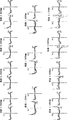
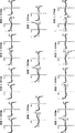
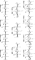
- FIG. 3 is a lateral aberration diagram of the imaging lens system according to Example 1 of the invention. It is a lateral aberration diagram of the imaging lens system according to Example 2 of the present invention.
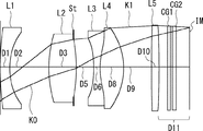
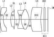
- FIG. 1 shows a cross-sectional view of an imaging lens system 1 which is an example of an embodiment of the present invention, and corresponds to Example 1 described later.
- the left side in the figure is the object side
- the right side is the image side
- light rays enter the imaging lens system 1 from the object side.
- the imaging lens system 1 includes, in order from the object side, a first lens L1 made of a negative meniscus lens having a convex shape on the object side and a second lens L2 made of a positive lens having a convex shape on the object side.
- An aperture stop St a third lens L3 made of a negative lens, a fourth lens L4 made of a positive lens having a convex shape on the object side, and a fifth lens L5 made of a meniscus lens having a concave shape on the image side.
- the imaging lens system 1 includes an aperture stop St disposed on the object side or the image side of the second lens L2.
- the aperture stop St is preferably disposed at a position adjacent to the object side or the image side of the second lens L2.
- the image side lens surface of the third lens L3 and the object side lens surface of the fourth lens L4 are bonded together.
- the principal ray K0 at the maximum field angle (maximum field of view) of the imaging lens system 1 and the lenses (third lens L3, fourth lens L4, and fifth lens L5) located on the image side from the aperture stop St are effective.
- the upper ray K1 at the maximum angle of view passing through the upper end of the diameter (the upper marginal ray of the maximum angle of view) is described.
- the upper light beam K1 at the maximum angle of view from the fourth lens L4 to the fifth lens L5 can be directed in the direction of the optical axis Z.
- the effective diameters of the third lens L3 and the fourth lens L4 can be increased. Therefore, the degree of freedom in designing the third lens L3 and the fourth lens L4 is increased, so that lateral aberration and curvature of field at the imaging position of the imaging lens system 1 can be reduced.
- FIG. 1 also shows an imaging element 2 at the imaging position of the imaging lens system 1 in consideration of the case where the imaging lens system 1 is applied to an imaging apparatus.
- the imaging element 2 receives an image formed by the imaging lens system 1 and converts it into an electrical signal.
- the image pickup device 2 includes, for example, a CCD (Charge-Coupled Device) image sensor, a CMOS (Complementary Metal-Oxide Semiconductor) image sensor, or the like.
- an image sensor cover glass and various filters are arranged according to the configuration of the image pickup apparatus. You may do it.
- the first cover glass CG1 and the second cover glass CG2 are disposed between the fifth lens L5 and the imaging element 2.
- the thickness of the first cover glass CG1 is 0.3 mm, and the thickness of the second cover glass CG2 is 0.4 mm. If necessary, the material, thickness, and number of the glass plate may be changed, or the glass plate may be eliminated.
- a flat cover glass disposed on the object side of the imaging lens system 1 may be further included. Thereby, it is possible to prevent the first lens L1 of the imaging lens system 1 from being scratched and soiled.
- the fifth lens L5 is a meniscus lens having negative power, and it is desirable that the following conditional expression (1) is satisfied.
- f The focal length of the entire lens system of the imaging lens system 1
- f5 The focal length of the fifth lens L5.
- Conditional expression (1) more preferably satisfies ⁇ 3.6 ⁇ f5 / f ⁇ ⁇ 2.2.
- the back focus of the imaging lens system 1 can be lengthened.
- the imaging lens system 1 can lengthen the flange back, and thus the components such as the filters described above can be inserted into the vacant space.
- the flange back refers to the distance from the position closest to the image plane outside the effective diameter of the image side lens surface of the fifth lens L5 to the image plane IM.
- f5 / f when f5 / f is set to ⁇ 4 or more, deterioration of lateral aberration can be suppressed.
- the flange back By setting f5 / f to ⁇ 1.5 or less, the flange back can be lengthened. Specifically, the flange back can be taken long so as to satisfy the following conditional expression (2).
- FB an air conversion distance from a position closest to the image plane to the image plane IM outside the effective diameter of the image side lens surface of the fifth lens L5
- f a focal length of the entire lens system of the imaging lens system 1.
- the conditional expression (2) satisfies 0.67 ⁇ FB / f ⁇ 0.58.
- the height of the light beam from the optical axis Z in the fourth lens L4 becomes relatively high by making the fifth lens L5 a negative meniscus lens having a concave shape on the image side.
- the effective diameters of the fourth lens L4 and the third lens L3 can be increased, and the degree of freedom in designing the lens surfaces of the fourth lens L4 and the third lens L3 is increased.
- the lateral aberration and the longitudinal chromatic aberration of the imaging lens system 1 can be reduced. Specifically, by satisfying the following conditional expression (3), the lateral aberration and the longitudinal chromatic aberration of the imaging lens system 1 can be further reduced.
- L4R2D The effective diameter of the image side lens surface of the fourth lens
- L4 L5R1D The effective diameter of the object side lens surface of the fifth lens L5.
- the shape of the image side lens surface of the fifth lens L5 does not have an extreme value at which the concave shape is switched to the convex shape in the range from the optical axis Z to the lens effective diameter end. Further, it is desirable that the radius of curvature of the image side lens surface of the fifth lens L5 satisfies the following conditional expression (4).
- f focal length L5R2R of the entire lens system of the imaging lens system 1: a radius of curvature of the image side lens surface of the fifth lens L5.
- conditional expression (4) satisfies 0.7 ⁇ L5R2R / f ⁇ 1.1.
- the imaging lens system 1 when the F value is less than 2.0, it is preferable that the following conditional expressions (5) to (8) are satisfied. Thereby, the lateral aberration and the field curvature of the imaging lens system 1 can be further reduced.
- f1 focal length of the first lens
- L1 f2 focal length of the second lens
- L2 f3 focal length of the third lens
- L3 f4 focal length of the fourth lens
- L4 f focal length of the entire lens system of the imaging lens system 1 To do.
- Conditional expression (5) preferably satisfies ⁇ 1.7 ⁇ f1 / f ⁇ ⁇ 1.1, and more preferably satisfies ⁇ 1.7 ⁇ f1 / f ⁇ ⁇ 1.3.
- Conditional expression (6) more preferably satisfies 0.8 ⁇ f2 / f ⁇ 1.3, and more preferably satisfies 0.8 ⁇ f2 / f ⁇ 1.1.
- Conditional expression (8) more preferably satisfies 1.0 ⁇ f4 / f ⁇ 1.4.
- the second lens L2 and the fourth lens L4 are biconvex lenses and the third lens L3 is a biconcave lens, and satisfies the following conditional expression (9). Thereby, the chromatic aberration of the imaging lens system 1 can be reduced.
- ⁇ 3 Abbe number of the third lens L3
- ⁇ 4 Abbe number of the fourth lens L4.
- the cemented lens of the third lens L3 and the fourth lens L4 it is preferable to decrease the Abbe number of the third lens L3 having negative power and increase the Abbe number of the fourth lens L4 having positive power. . Thereby, the chromatic aberration of the imaging lens system 1 can be corrected.
- the imaging lens system 1 preferably satisfies the following conditional expression (10). 0.36 ⁇ ⁇ 345 / ⁇ 12 ⁇ 0.52 (10) However, ⁇ 12: combined power of the first lens L1 and the second lens L2 ⁇ 345: combined power of the third lens L3, the fourth lens L4, and the fifth lens L5.
- ⁇ 12 combined power of the first lens L1 and the second lens L2
- ⁇ 345 combined power of the third lens L3, the fourth lens L4, and the fifth lens L5.
- the focal position change due to the temperature change is caused by the refractive index change and the lens shape change due to the temperature change of each lens.
- Glass often has a refractive index that increases as the temperature rises.
- plastic often has a refractive index that decreases as the temperature rises.
- the amount of change in refractive index with respect to temperature change of plastic is considerably large.
- the linear expansion coefficient of plastic is larger than that of glass. Therefore, the change in the lens shape due to the expansion or contraction of the lens at the time of temperature change is larger in plastic than in glass.
- the first lens L1 and the second lens L2 are glass lenses
- the third lens L3, the fourth lens L4, and the fifth lens L5 are plastic lenses, by satisfying 0.36 ⁇ ⁇ 345 / ⁇ 12 ⁇ 0.52
- the focal position change of the first lens L1 and the second lens L2 is canceled by the focal position change of the third lens L3, the fourth lens L4, and the fifth lens L5, and the focal position of the entire lens system of the imaging lens system 1 Change can be reduced.
- the imaging lens system 1 of the present embodiment by appropriately setting the material of each lens, the shape of each surface, and the power of each lens, the F value is small, the imaging performance is high, and the focal position with respect to temperature change An imaging lens system with little change can be provided at low cost.
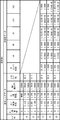
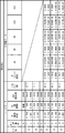
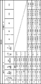
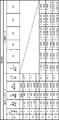
- Example 1 The configuration of the imaging lens system 1 according to Example 1 is as shown in FIG. 3, and a table of corresponding basic lens data and aspherical data is shown in FIG.
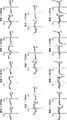
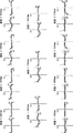
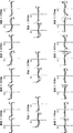
- FIG. 23 shows a lateral aberration diagram of this example
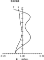
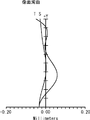
- FIG. 33 shows a field curvature diagram
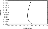
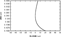
- FIG. 43 shows an axial chromatic aberration diagram.
- the lateral aberration diagram shows 11 sets including an angle of view 0 (image heights on the image plane are 0.0, 0.3, 0.6, 0.9, 1.2, 1.5, 1.8, 2 .1, 2.4, 3.044, 3.278), a total of 22 graphs are shown.
- the horizontal axis of the graph represents the relative pupil coordinates in the Y direction or X direction at each angle of view, and the vertical axis represents the lateral aberration value in the direction perpendicular to the optical axis on the image plane.
- Each graph shows lateral aberration values at five wavelengths.
- the main wavelength of 0.546 ⁇ m is indicated by a solid line.
- the other four wavelengths are shown by four types of broken lines, and the wavelengths of 0.486 ⁇ m, 0.436 ⁇ m, 0.656 ⁇ m, and 0.588 ⁇ m are shown from the shorter broken line length, respectively.
- T represents the tangential direction
- S represents the sagittal direction.
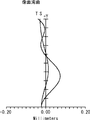
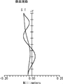
- the horizontal axis represents the field curvature value, with the plus side representing the far direction and the minus side representing the near direction.
- the vertical axis represents the relative field angle normalized by the maximum field angle.
- the horizontal axis represents the focal position
- the positive side represents the far direction
- the negative side represents the near direction
- the vertical axis represents the wavelength
- the left side of the figure is the object side
- the right side is the image side
- the image plane is shown as IM.
- the aperture stop St does not represent a shape or size but a position on the optical axis Z.
- Si indicates the i-th surface that increases sequentially toward the image side with the surface of the component closest to the object side as the first.
- Ri represents the radius of curvature of the i-th surface.
- Di represents a distance (surface interval) on the optical axis Z between the i-th surface Si and the i + 1-th surface Si + 1.
- Ndi represents the refractive index with respect to the d-line (wavelength 0.5876 ⁇ m) of the medium having the surface interval Di.
- the basic lens data includes the object plane located at infinity and the aperture stop St (lens No. column).
- the radius of curvature is described as positive when convex on the object side and negative when convex on the image side.
- the unit of the radius of curvature and the surface interval is mm.
- the aspheric coefficient of each lens surface is described as aspheric data, and the surface without the aspheric data is a spherical surface.
- the aspherical shape is expressed by the following equation.
- Sag (h) (h 2 / R) / ⁇ 1 + ⁇ (1 ⁇ (1 + K) ⁇ h 2 / R 2 ) ⁇ + A4 ⁇ h 4 + A6 ⁇ h 6 + A8 ⁇ h 8 + A10 ⁇ h 10 + A12 ⁇ h 12
- h lens surface height in the direction perpendicular to the optical axis
- Sag (h) the optical axis Z direction from the tangential plane at the apex of the aspheric surface on the optical axis Z to the position on the aspheric surface at height h
- Distance (sag amount) radius of curvature
- K conic coefficient (conical coefficient)
- An An n-order aspherical coefficient.
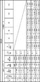
- Example 2 The configuration of the imaging lens system 1 according to Example 2 is as shown in FIG. 4, and corresponding basic lens data and aspherical data are shown in FIG. Further, FIG. 24 shows a lateral aberration diagram of this example, FIG. 34 shows a field curvature diagram, and FIG. 44 shows an axial chromatic aberration diagram.
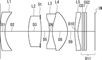
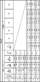
- Example 3 The configuration of the imaging lens system 1 according to Example 3 is as shown in FIG. 5, and corresponding basic lens data and aspherical data are shown in FIG.
- FIG. 25 shows a lateral aberration diagram of this example
- FIG. 35 shows a field curvature diagram
- FIG. 45 shows an axial chromatic aberration diagram.
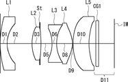
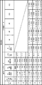
- Example 4 The configuration of the imaging lens system 1 according to Example 4 is as shown in FIG. 6, and corresponding basic lens data and aspherical data are shown in FIG.
- FIG. 26 shows a lateral aberration diagram of this example
- FIG. 36 shows a field curvature diagram
- FIG. 46 shows an axial chromatic aberration diagram.
- Example 5 The configuration of the imaging lens system 1 according to Example 5 is as shown in FIG. 7, and corresponding basic lens data and aspherical data are shown in FIG. Further, FIG. 27 shows a lateral aberration diagram of this example, FIG. 37 shows a field curvature diagram, and FIG. 47 shows an axial chromatic aberration diagram.
- Example 6 The configuration of the imaging lens system 1 according to Example 6 is as shown in FIG. 8, and corresponding basic lens data and aspherical data are shown in FIG.
- FIG. 28 is a lateral aberration diagram of this example
- FIG. 38 is a curvature of field diagram
- FIG. 48 is a longitudinal chromatic aberration diagram.
- Example 7 The configuration of the imaging lens system 1 according to Example 7 is as shown in FIG. 9, and the corresponding basic lens data and aspherical data are shown in FIG.
- FIG. 29 shows a lateral aberration diagram of this example
- FIG. 39 shows a field curvature diagram
- FIG. 49 shows an axial chromatic aberration diagram.
- Example 8 The configuration of the imaging lens system 1 according to Example 8 is as shown in FIG. 10, and corresponding basic lens data and aspherical data are shown in FIG. Further, FIG. 30 shows a lateral aberration diagram of this example, FIG. 40 shows a curvature of field diagram, and FIG. 50 shows an axial chromatic aberration diagram.
- Example 9 The configuration of the imaging lens system 1 according to Example 9 is as shown in FIG. 11, and corresponding basic lens data and aspherical data are shown in FIG. Further, FIG. 31 shows a lateral aberration diagram of this example, FIG. 41 shows a field curvature diagram, and FIG. 51 shows an axial chromatic aberration diagram.
- FIG. 32 shows a lateral aberration diagram of this example
- FIG. 42 shows a field curvature diagram
- FIG. 52 shows an axial chromatic aberration diagram.
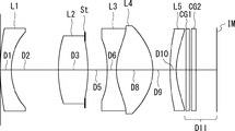
- FIG. 2 shows a cross-sectional view of a comparative example of the present invention.
- the first lens L1 to the fourth lens L4 have the same configuration as that of the imaging lens system 1, but are different from the imaging lens system 1 according to the present embodiment in that the fifth lens L5 is a biconvex positive lens. .
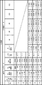
- FIG. 22 shows the F value, focal length f, and characteristic values (f1 / f to f5 / f, FB /) of the conditional expressions (1) to (10) of the imaging lens systems 1 of Examples 1 to 9 and the comparative example. f, L4R2D, L5R1D, L5R2R / f, ⁇ 345 / ⁇ 12).
- FIG. 22 shows the amount of change in focal position (paraxial focus fluctuation amount) of the imaging lens system 1 when the temperature is changed from room temperature (25 ° C.) to 85 ° C. or ⁇ 40 ° C. in Examples 1 to 9. .
- Examples 1 to 9 do not satisfy any of conditional expressions (1) to (10).
- conditional expression (1) Examples 1 to 7 are satisfied, and Examples 8 and 9 are not satisfied.
- conditional expression (2) Examples 1 to 8 are satisfied, and Example 9 is not satisfied.
- conditional expression (3) Examples 1 to 3 and 5 are satisfied, and Examples 4 and 6 to 9 are not satisfied.
- the comparative example does not satisfy the conditional expressions (1), (3), (4), and (10).
- Examples 1 to 9 have smaller lateral aberration and curvature of field than the comparative example.
- Examples 1 to 3 and 5 that satisfy conditional expression (3) have smaller axial chromatic aberration.
- the axial chromatic aberration is the same as in Examples 1 to 3, but the lateral aberration is slightly larger.
- the amount of change in the focal position of the imaging lens system 1 (paraxial focus fluctuation amount) when the temperature is changed from room temperature (25 ° C.) to 85 ° C. or ⁇ 40 ° C. ) Is suppressed to 0.024 mm or less.
- imaging lens system 1 of the present invention is not limited to that of the above-described embodiment, and various other modes can be changed.
Landscapes
- Physics & Mathematics (AREA)
- General Physics & Mathematics (AREA)
- Optics & Photonics (AREA)
- Lenses (AREA)
Abstract
Description
物体側から順に、物体側に凸形状の負のメニスカスレンズからなる第1レンズと、物体側に凸形状の正レンズからなる第2レンズと、像側に凹形状の負レンズからなる第3レンズと、物体側が凸形状の正レンズからなる第4レンズと、像側に凹形状のメニスカスレンズからなる第5レンズとを備え、
さらに、前記第2レンズの物体側又は像側に配置された開口絞りを備え、
前記第3レンズの像側レンズ面と前記第4レンズの物体側レンズ面とが貼り合わされている。
但し、
f:撮像レンズ系1のレンズ系全体の焦点距離
f5:第5レンズL5の焦点距離
とする。
なお、条件式(1)は、-3.6≦f5/f≦-2.2を満足することがより好ましい。
但し
FB:第5レンズL5の像側レンズ面の有効径の外側において最も像面に近い位置から像面IMまでの空気換算距離
f:撮像レンズ系1のレンズ系全体の焦点距離
とする。
なお、条件式(2)は、0.67≧FB/f≧0.58を満足することがより好ましい。
但し、
L4R2D:第4レンズL4の像側レンズ面の有効径
L5R1D:第5レンズL5の物体側レンズ面の有効径
とする。
但し、
f:撮像レンズ系1のレンズ系全体の焦点距離
L5R2R:第5レンズL5の像側レンズ面の曲率半径
とする。
なお、条件式(4)は、0.7≦L5R2R/f≦1.1を満足することがより好ましい。
0.5≦f2/f≦1.6 (6)
-2.8≦f3/f≦-0.5 (7)
0.6≦f4/f≦1.7 (8)
但し、
f1:第1レンズL1の焦点距離
f2:第2レンズL2の焦点距離
f3:第3レンズL3の焦点距離
f4:第4レンズL4の焦点距離
f:撮像レンズ系1のレンズ系全体の焦点距離
とする。
但し、
ν3:第3レンズL3のアッベ数
ν4:第4レンズL4のアッベ数
とする。
0.36≦ρ345/ρ12≦0.52 (10)
但し、
ρ12:第1レンズL1及び第2レンズL2の合成パワー
ρ345:第3レンズL3、第4レンズL4及び第5レンズL5の合成パワー
とする。
ここで、第1レンズL1及び第2レンズL2の合成焦点距離をf12とすると、ρ12=1/f12と表せる。第3レンズL3、第4レンズL4及び第5レンズL5の合成焦点距離をf345とすると、ρ345=1/f345と表せる。
〈実施例1〉
実施例1に係る撮像レンズ系1の構成は図3に示す通りであり、対応する基本レンズデータ及び非球面データの表を図12に示す。また、本実施例の横収差図を図23、像面湾曲図を図33、軸上色収差図を図43に示す。
Sag(h)=(h2/R)/{1+√(1-(1+K)×h2/R2)}
+A4×h4+A6×h6+A8×h8+A10×h10+A12×h12
但し
h:光軸に垂直な方向のレンズ面の高さ
Sag(h):光軸Z上の非球面の頂点における接平面から、高さhにおける非球面上の位置までの光軸Z方向の距離(サグ量)
R:曲率半径
K:コーニック係数(円錐係数)
An:n次の非球面係数
とする。
実施例2に係る撮像レンズ系1の構成は、図4に示す通りであり、対応する基本レンズデータ及び非球面データを図13に示す。また、本実施例の横収差図を図24、像面湾曲図を図34、軸上色収差図を図44に示す。
実施例3に係る撮像レンズ系1の構成は、図5に示す通りであり、対応する基本レンズデータ及び非球面データを図14に示す。また、本実施例の横収差図を図25、像面湾曲図を図35、軸上色収差図を図45に示す。
実施例4に係る撮像レンズ系1の構成は、図6に示す通りであり、対応する基本レンズデータ及び非球面データを図15に示す。また、本実施例の横収差図を図26、像面湾曲図を図36、軸上色収差図を図46に示す。
実施例5に係る撮像レンズ系1の構成は、図7に示す通りであり、対応する基本レンズデータ及び非球面データを図16に示す。また、本実施例の横収差図を図27、像面湾曲図を図37、軸上色収差図を図47に示す。
実施例6に係る撮像レンズ系1の構成は、図8に示す通りであり、対応する基本レンズデータ及び非球面データを図17に示す。また、本実施例の横収差図を図28、像面湾曲図を図38、軸上色収差図を図48に示す。
実施例7に係る撮像レンズ系1の構成は、図9に示す通りであり、対応する基本レンズデータ及び非球面データを図18に示す。また、本実施例の横収差図を図29、像面湾曲図を図39、軸上色収差図を図49に示す。
実施例8に係る撮像レンズ系1の構成は、図10に示す通りであり、対応する基本レンズデータ及び非球面データを図19に示す。また、本実施例の横収差図を図30、像面湾曲図を図40、軸上色収差図を図50に示す。
実施例9に係る撮像レンズ系1の構成は、図11に示す通りであり、対応する基本レンズデータ及び非球面データを図20に示す。また、本実施例の横収差図を図31、像面湾曲図を図41、軸上色収差図を図51に示す。
比較例に係る撮像レンズ系の構成は、図2に示す通りであり、対応する基本レンズデータ及び非球面データを図21に示す。また、本実施例の横収差図を図32、像面湾曲図を図42、軸上色収差図を図52に示す。
図22に実施例1~9及び比較例の撮像レンズ系1のF値、焦点距離f、及び前述の条件式(1)~(10)の特性値(f1/f~f5/f、FB/f、L4R2D、L5R1D、L5R2R/f、ρ345/ρ12)を示す。また、図22に、実施例1~9において、常温(25℃)から85℃又は-40℃に変化させたときの撮像レンズ系1の焦点位置の変化量(近軸ピント変動量)を示す。
2 撮像素子
Z 光軸
K0 最大画角における主光線
K1 最大画角における上光線
L1 第1レンズ
L2 第2レンズ
L3 第3レンズ
L4 第4レンズ
L5 第5レンズ
CG1 第1カバーガラス
CG2 第2カバーガラス
St 開口絞り
IM 像面
Si 面番号(i=0、1、2、3、・・・)
Ri i番目の面の曲率半径(i=1、2、3、・・・)
Di i番目の面とi+1番目の面との光軸上の面間隔(i=1、2、3、・・・)
Ndi i番目の面からi+1番目の面までの媒質のd線に対する屈折率(i=1、2、3、・・・)
νdj j番目のレンズの媒質のアッベ数(j=1、2、3、4、5)
Claims (11)
- 物体側から順に、物体側に凸形状の負のメニスカスレンズからなる第1レンズと、物体側に凸形状の正レンズからなる第2レンズと、像側に凹形状の負レンズからなる第3レンズと、物体側が凸形状の正レンズからなる第4レンズと、像側に凹形状のメニスカスレンズからなる第5レンズとを備え、
さらに、前記第2レンズの物体側又は像側に配置された開口絞りを備え、
前記第3レンズの像側レンズ面と前記第4レンズの物体側レンズ面とが貼り合わされている
撮像レンズ系。 - 前記第5レンズは負のメニスカスレンズであり、下記条件式を満足することを特徴とする請求項1に記載の撮像レンズ系。
-4≦f5/f≦-1.5
但し、
f:レンズ系全体の焦点距離
f5:前記第5レンズの焦点距離
とする。 - 下記条件式を満足することを特徴とする請求項1又は2に記載の撮像レンズ系。
FB/f≧0.52
但し、
f:レンズ系全体の焦点距離
FB:前記第5レンズの像側レンズ面の有効径の外側において最も像面に近い位置から像面までの空気換算距離
とする。 - 下記条件式を満足することを特徴とする請求項1~3のいずれか1項に記載の撮像レンズ系。
L4R2D≧L5R1D
但し、
L4R2D:前記第4レンズの像側レンズ面の有効径
L5R1D:前記第5レンズの物体側レンズ面の有効径
とする。 - 前記第5レンズの像側レンズ面の形状は、光軸から有効径端までの範囲で凹形状が凸形状に切り替わる極値を有さず、かつ、下記条件式を満足することを特徴とする請求項1~4のいずれか1項に記載の撮像レンズ系
0.5≦L5R2R/f≦3
但し、
f:レンズ系全体の焦点距離
L5R2R:前記第5レンズの像側レンズ面の曲率半径
とする。 - 下記条件式を満足することを特徴とする請求項1~5のいずれか1項に記載の撮像レンズ系。
0.36≦ρ345/ρ12≦0.52
但し、
ρ12:前記第1レンズ及び前記第2レンズの合成パワー
ρ345:前記第3レンズ、前記第4レンズ及び前記第5レンズの合成パワー
とする。 - 前記第3レンズ、前記第4レンズ及び前記第5レンズの材質がプラスチックであることを特徴とする請求項1~6のいずれか1項に記載の撮像レンズ系。
- 前記第1レンズ及び前記第2レンズの材質がガラスであることを特徴とする請求項7に記載の撮像レンズ系。
- F値が2.0未満であり、下記条件式の全てを満足することを特徴とする請求項1~8のいずれか1項に記載の撮像レンズ系
-2.2≦f1/f≦-0.9
0.5≦f2/f≦1.6
-2.8≦f3/f≦-0.5
0.6≦f4/f≦1.7
但し、
f1:前記第1レンズの焦点距離
f2:前記第2レンズの焦点距離
f3:前記第3レンズの焦点距離
f4:前記第4レンズの焦点距離
f:レンズ系全体の焦点距離
とする。 - 前記第2レンズ及び前記第4レンズが両凸レンズ、前記第3レンズが両凹レンズであり、
下記条件式を満足することを特徴とする請求項1~9のいずれか1項に記載の撮像レンズ系。
ν4-ν3≧15
但し、
ν3:前記第3レンズのアッベ数
ν4:前記第4レンズのアッベ数
とする。 - 請求項1~10のいずれか1項に記載の撮像レンズ系と、
前記撮像レンズ系の物体側に配置された平板状のカバーガラスと、
前記撮像レンズ系の焦点位置に配置された撮像素子と、を備えることを特徴とする撮像装置。
Priority Applications (2)
| Application Number | Priority Date | Filing Date | Title |
|---|---|---|---|
| JP2015540400A JP5872123B2 (ja) | 2013-10-03 | 2014-10-03 | 撮像レンズ系及び撮像装置 |
| US15/022,117 US9810877B2 (en) | 2013-10-03 | 2014-10-03 | Imaging lens system and imaging device |
Applications Claiming Priority (2)
| Application Number | Priority Date | Filing Date | Title |
|---|---|---|---|
| JP2013208450 | 2013-10-03 | ||
| JP2013-208450 | 2013-10-03 |
Publications (1)
| Publication Number | Publication Date |
|---|---|
| WO2015049877A1 true WO2015049877A1 (ja) | 2015-04-09 |
Family
ID=52778480
Family Applications (1)
| Application Number | Title | Priority Date | Filing Date |
|---|---|---|---|
| PCT/JP2014/005050 Ceased WO2015049877A1 (ja) | 2013-10-03 | 2014-10-03 | 撮像レンズ系及び撮像装置 |
Country Status (3)
| Country | Link |
|---|---|
| US (1) | US9810877B2 (ja) |
| JP (2) | JP5872123B2 (ja) |
| WO (1) | WO2015049877A1 (ja) |
Cited By (2)
| Publication number | Priority date | Publication date | Assignee | Title |
|---|---|---|---|---|
| US10656389B2 (en) | 2014-05-26 | 2020-05-19 | Largan Precision Co., Ltd. | Imaging optical system, image capturing device and mobile terminal |
| CN112255773A (zh) * | 2020-10-16 | 2021-01-22 | 福建福光股份有限公司 | 一种制冷型大视场中波红外光学系统 |
Families Citing this family (6)
| Publication number | Priority date | Publication date | Assignee | Title |
|---|---|---|---|---|
| TWI678572B (zh) * | 2017-08-21 | 2019-12-01 | 鴻海精密工業股份有限公司 | 取像鏡頭 |
| TWI685690B (zh) | 2018-03-14 | 2020-02-21 | 先進光電科技股份有限公司 | 光學成像系統(一) |
| WO2019239578A1 (ja) * | 2018-06-15 | 2019-12-19 | オリンパス株式会社 | 対物光学系及びそれを用いた硬性鏡用光学系、硬性鏡 |
| CN111352224A (zh) * | 2019-11-22 | 2020-06-30 | 莆田学院 | 一种折反射全景成像系统及其成像方法 |
| CN114397746B (zh) * | 2022-01-22 | 2023-11-24 | 福建福光天瞳光学有限公司 | 一种日夜两用定焦镜头及其成像方法 |
| TWI836347B (zh) | 2022-02-16 | 2024-03-21 | 大立光電股份有限公司 | 影像擷取鏡片系統組、取像裝置及電子裝置 |
Citations (6)
| Publication number | Priority date | Publication date | Assignee | Title |
|---|---|---|---|---|
| JP2002131634A (ja) * | 2000-10-27 | 2002-05-09 | Nidec Copal Corp | 小型レンズ |
| JP2005114787A (ja) * | 2003-10-03 | 2005-04-28 | Nidec Copal Corp | 撮像レンズ |
| JP2006091046A (ja) * | 2004-09-21 | 2006-04-06 | Nidec Copal Corp | 読取用レンズ |
| JP2009186625A (ja) * | 2008-02-05 | 2009-08-20 | Fujinon Corp | 撮像レンズおよびこの撮像レンズを用いた撮像装置 |
| JP2011076021A (ja) * | 2009-10-02 | 2011-04-14 | Nikon Corp | 広角レンズ、光学機器、および広角レンズの製造方法 |
| JP2011076022A (ja) * | 2009-10-02 | 2011-04-14 | Nikon Corp | 広角レンズ、光学機器、および広角レンズの製造方法 |
Family Cites Families (9)
| Publication number | Priority date | Publication date | Assignee | Title |
|---|---|---|---|---|
| JP2596810B2 (ja) * | 1988-09-12 | 1997-04-02 | オリンパス光学工業株式会社 | 内視鏡用光学系 |
| US7663813B2 (en) * | 2008-01-02 | 2010-02-16 | Newmax Technology Co., Ltd. | Imaging lens module |
| JP5143595B2 (ja) | 2008-03-10 | 2013-02-13 | 富士フイルム株式会社 | 撮像レンズおよび撮像装置 |
| US8107175B2 (en) | 2009-10-02 | 2012-01-31 | Nikon Corporation | Wide-angle lens, optical apparatus, and method for manufacturing wide-angle lens |
| JP5496809B2 (ja) * | 2010-07-29 | 2014-05-21 | 富士フイルム株式会社 | 撮像レンズおよび撮像装置 |
| TWI435137B (zh) * | 2011-03-09 | 2014-04-21 | Largan Precision Co | 攝像用光學鏡片組 |
| TWI431357B (zh) * | 2011-07-05 | 2014-03-21 | Asia Optical Co Inc | Miniature lens |
| CN103917908B (zh) * | 2011-11-09 | 2016-05-18 | 富士胶片株式会社 | 摄像透镜以及摄像装置 |
| CN104011577B (zh) * | 2011-12-27 | 2016-03-30 | 富士胶片株式会社 | 摄像透镜和摄像装置 |
-
2014
- 2014-10-03 US US15/022,117 patent/US9810877B2/en active Active
- 2014-10-03 JP JP2015540400A patent/JP5872123B2/ja active Active
- 2014-10-03 WO PCT/JP2014/005050 patent/WO2015049877A1/ja not_active Ceased
-
2016
- 2016-01-12 JP JP2016003430A patent/JP5898395B1/ja active Active
Patent Citations (6)
| Publication number | Priority date | Publication date | Assignee | Title |
|---|---|---|---|---|
| JP2002131634A (ja) * | 2000-10-27 | 2002-05-09 | Nidec Copal Corp | 小型レンズ |
| JP2005114787A (ja) * | 2003-10-03 | 2005-04-28 | Nidec Copal Corp | 撮像レンズ |
| JP2006091046A (ja) * | 2004-09-21 | 2006-04-06 | Nidec Copal Corp | 読取用レンズ |
| JP2009186625A (ja) * | 2008-02-05 | 2009-08-20 | Fujinon Corp | 撮像レンズおよびこの撮像レンズを用いた撮像装置 |
| JP2011076021A (ja) * | 2009-10-02 | 2011-04-14 | Nikon Corp | 広角レンズ、光学機器、および広角レンズの製造方法 |
| JP2011076022A (ja) * | 2009-10-02 | 2011-04-14 | Nikon Corp | 広角レンズ、光学機器、および広角レンズの製造方法 |
Cited By (5)
| Publication number | Priority date | Publication date | Assignee | Title |
|---|---|---|---|---|
| US10656389B2 (en) | 2014-05-26 | 2020-05-19 | Largan Precision Co., Ltd. | Imaging optical system, image capturing device and mobile terminal |
| US11415780B2 (en) | 2014-05-26 | 2022-08-16 | Largan Precision Co., Ltd. | Imaging optical system, image capturing device and mobile terminal |
| US11835693B2 (en) | 2014-05-26 | 2023-12-05 | Largan Precision Co., Ltd. | Imaging optical system, image capturing device and mobile terminal |
| CN112255773A (zh) * | 2020-10-16 | 2021-01-22 | 福建福光股份有限公司 | 一种制冷型大视场中波红外光学系统 |
| CN112255773B (zh) * | 2020-10-16 | 2022-08-23 | 福建福光股份有限公司 | 一种制冷型大视场中波红外光学系统 |
Also Published As
| Publication number | Publication date |
|---|---|
| JP5872123B2 (ja) | 2016-03-01 |
| JPWO2015049877A1 (ja) | 2017-03-09 |
| JP2016103035A (ja) | 2016-06-02 |
| US20160223782A1 (en) | 2016-08-04 |
| JP5898395B1 (ja) | 2016-04-06 |
| US9810877B2 (en) | 2017-11-07 |
Similar Documents
| Publication | Publication Date | Title |
|---|---|---|
| CN208752293U (zh) | 摄像镜头 | |
| CN207586515U (zh) | 摄像镜头 | |
| CN111090165B (zh) | 摄像镜头 | |
| JP5898395B1 (ja) | 撮像レンズ系及び撮像装置 | |
| JP4949871B2 (ja) | 撮像レンズ、および該撮像レンズを備えた撮像装置 | |
| JP6353756B2 (ja) | 撮像レンズ系及び撮像装置 | |
| US9176300B2 (en) | Imaging lens assembly, imaging device and vehicle photographing device | |
| JP6740904B2 (ja) | 撮像レンズおよび撮像装置 | |
| JP7002508B2 (ja) | 撮像レンズ | |
| JP6741019B2 (ja) | 撮像レンズ及び車載用撮像装置 | |
| CN111796393A (zh) | 摄像镜头 | |
| CN101923206B (zh) | 变焦镜头 | |
| JP2016194653A (ja) | 撮像光学系及びそれを有する撮像装置 | |
| US9389398B2 (en) | Imaging lens, and imaging apparatus including the imaging lens | |
| JP6711361B2 (ja) | 撮像レンズ | |
| CN101082695A (zh) | 广角摄像透镜 | |
| JP2008058387A (ja) | 超広角レンズ | |
| JP7112894B2 (ja) | 撮像レンズ | |
| JP6571840B2 (ja) | 撮像レンズ系及び撮像装置 | |
| JP2016109871A (ja) | 撮像光学系 | |
| CN113568136B (zh) | 摄像镜头 | |
| JP2022173832A (ja) | 撮像レンズ系及び撮像装置 | |
| JP2022163952A (ja) | 撮像レンズ | |
| JP2011128210A (ja) | 撮像レンズおよび撮像装置 | |
| JP2009145479A (ja) | 撮像レンズユニット及びカメラモジュール |
Legal Events
| Date | Code | Title | Description |
|---|---|---|---|
| 121 | Ep: the epo has been informed by wipo that ep was designated in this application |
Ref document number: 14850553 Country of ref document: EP Kind code of ref document: A1 |
|
| ENP | Entry into the national phase |
Ref document number: 2015540400 Country of ref document: JP Kind code of ref document: A |
|
| WWE | Wipo information: entry into national phase |
Ref document number: 15022117 Country of ref document: US |
|
| NENP | Non-entry into the national phase |
Ref country code: DE |
|
| 122 | Ep: pct application non-entry in european phase |
Ref document number: 14850553 Country of ref document: EP Kind code of ref document: A1 |