WO2015046596A1 - 磁気ディスク用ガラス基板の製造方法及び磁気ディスクの製造方法 - Google Patents
磁気ディスク用ガラス基板の製造方法及び磁気ディスクの製造方法 Download PDFInfo
- Publication number
- WO2015046596A1 WO2015046596A1 PCT/JP2014/076187 JP2014076187W WO2015046596A1 WO 2015046596 A1 WO2015046596 A1 WO 2015046596A1 JP 2014076187 W JP2014076187 W JP 2014076187W WO 2015046596 A1 WO2015046596 A1 WO 2015046596A1
- Authority
- WO
- WIPO (PCT)
- Prior art keywords
- glass substrate
- grinding
- fixed abrasive
- magnetic disk
- abrasive
- Prior art date
- Legal status (The legal status is an assumption and is not a legal conclusion. Google has not performed a legal analysis and makes no representation as to the accuracy of the status listed.)
- Ceased
Links
Images



Classifications
-
- G—PHYSICS
- G11—INFORMATION STORAGE
- G11B—INFORMATION STORAGE BASED ON RELATIVE MOVEMENT BETWEEN RECORD CARRIER AND TRANSDUCER
- G11B5/00—Recording by magnetisation or demagnetisation of a record carrier; Reproducing by magnetic means; Record carriers therefor
- G11B5/84—Processes or apparatus specially adapted for manufacturing record carriers
- G11B5/8404—Processes or apparatus specially adapted for manufacturing record carriers manufacturing base layers
Definitions
- the present invention relates to a method for manufacturing a glass substrate for a magnetic disk mounted on a magnetic disk device such as a hard disk drive (HDD) and a method for manufacturing a magnetic disk.
- a magnetic disk device such as a hard disk drive (HDD)
- HDD hard disk drive
- a magnetic disk as one of information recording media mounted on a magnetic disk device such as a hard disk drive (HDD).
- a magnetic disk is configured by forming a thin film such as a magnetic layer on a substrate, and an aluminum substrate has been conventionally used as the substrate.
- the ratio of the glass substrate capable of narrowing the distance between the magnetic head and the magnetic disk as compared with the aluminum substrate is gradually increasing.
- the surface of the glass substrate is polished with high accuracy so as to increase the recording density so that the flying height of the magnetic head can be reduced as much as possible.
- HDDs high recording capacity and lower prices. In order to achieve this, it is necessary to further improve the quality and cost of glass substrates for magnetic disks. It is coming.
- high smoothness on the surface of the magnetic disk is indispensable for reducing the flying height (flying height) necessary for increasing the recording density.
- a substrate surface with a high smoothness is required in the end. Therefore, it is necessary to polish the glass substrate surface with high accuracy.
- further polishing is performed to reduce the surface roughness and microwaviness, thereby reducing the main surface. Has achieved extremely high smoothness.
- a diamond pad is a sheet of diamond particles or agglomerates in which some diamond particles are hardened with a binder such as glass, ceramic, metal, or resin, using a support material such as resin (for example, acrylic resin). It is fixed on the top.
- a resin layer containing diamond may be formed on the sheet, and then a groove may be formed in the resin layer to form a protrusion.
- the diamond pad referred to here is not necessarily a general name, but is referred to as a “diamond pad” for convenience of explanation in this specification.
- abrasive grains with a distorted shape are present between the surface plate and the glass and are non-uniform, so if the load on the abrasive grains is not constant and the load is concentrated, the surface of the surface plate Because of the low elasticity of cast iron, deep cracks enter the glass, the work-affected layer is deep, and the processing surface roughness of the glass also increases, so a large amount of removal was required in the subsequent mirror polishing process. It was difficult to reduce processing costs.
- the abrasive grains are uniformly present on the surface of the sheet, so that the load is not concentrated, and in addition, the abrasive is fixed to the sheet using resin. Therefore, even if a load is applied to the abrasive grains, the high elastic action of the resin fixing the abrasive grains makes the cracks (deformed layer) on the processed surface shallow, and the processed surface roughness can be reduced. The load on the machine (such as machining allowance) is reduced, and processing costs can be reduced. After the grinding process is finished, mirror polishing is performed to obtain a highly accurate plane.
- the surface roughness of the processed surface can be reduced, the load on the subsequent mirror polishing process is reduced, and the processing cost of the glass substrate is reduced.
- reduction is possible, according to the study of the present inventors, it has been found that there are the following problems.
- the density of the fixed abrasive grains has been increased (see Patent Document 2).
- the processing speed may not be increased only by increasing the density of the fixed abrasive grains. Further, it has been found that the processing speed varies even when diamond pads having the same abrasive density are used.
- the present inventor examined this cause, and when changing the fixed abrasive density, the dispersion state of the fixed abrasive in the pellet may be deteriorated, and the load applied to each fixed abrasive at this time is not uniform. In particular, it has been found that machining does not proceed at the initial stage of machining, and the machining speed decreases.
- the present invention has been made to solve such a conventional problem.
- the purpose of the present invention is to perform stable grinding by increasing the processing speed in grinding using fixed abrasive grains. It is providing the manufacturing method of the glass substrate for magnetic discs which can manufacture this glass substrate, and the manufacturing method of a magnetic disc using the glass substrate obtained by it.
- the present inventor found that the average inter-abrasive distance between the fixed abrasive wheels and the processing speed when the glass substrate was ground using the fixed abrasive wheels.
- a correlation is obtained in advance, a fixed abrasive wheel having an average inter-abrasive distance that provides a desired processing speed is selected based on the obtained correlation, and the selected fixed abrasive wheel is selected. It has been found that by using it, it is possible to increase the processing speed and perform stable grinding.
- the main surface is particularly suitable for grinding a glass substrate having a mirror surface. That is, in order to solve the above problems, the present invention has the following configuration.
- a method for producing a glass substrate for a magnetic disk comprising a grinding process for grinding a main surface of a glass substrate using a lubricating liquid and a surface plate on which a fixed abrasive wheel is disposed on a grinding surface, the fixed abrasive
- the grindstone includes fixed abrasive grains contained in a support material, and grinds the glass substrate using the average abrasive distance between the fixed abrasive grains on the grinding surface of the fixed abrasive grindstone and the fixed abrasive grindstone.
- a correlation with the processing speed in the case of processing is obtained in advance, a fixed abrasive wheel having an average inter-abrasive distance that provides a desired processing speed is selected based on the obtained correlation, and the selected fixed abrasive
- a method for producing a glass substrate for a magnetic disk comprising a grinding process for grinding a main surface of a glass substrate using a lubricating liquid and a surface plate on which a fixed abrasive wheel is disposed on a grinding surface, the fixed abrasive
- the grindstone includes fixed abrasive grains contained in a support material, and the average inter-abrasive distance of the fixed abrasive grains on the grinding surface of the fixed abrasive grindstone is 80 ⁇ m to 200 ⁇ m.
- (Configuration 5) The method for manufacturing a glass substrate for a magnetic disk according to any one of Structures 1 to 4, wherein the fixed abrasive grains include diamond abrasive grains.
- (Configuration 6) The method for producing a glass substrate for a magnetic disk according to any one of Structures 1 to 5, wherein the fixed abrasive is an abrasive grain or an abrasive aggregate in which a plurality of abrasive grains are hardened with a binder.
- (Configuration 7) The method of manufacturing a glass substrate for a magnetic disk according to any one of Structures 1 to 6, wherein the glass substrate is a glass substrate having a mirror-like main surface at the start of grinding.
- (Configuration 8) 8. The method for producing a glass substrate for a magnetic disk according to any one of Structures 1 to 7, wherein the processing load is 50 g / cm 2 to 200 g / cm 2 .
- a magnetic disk manufacturing method comprising forming at least a magnetic recording layer on a magnetic disk glass substrate manufactured by the method for manufacturing a magnetic disk glass substrate according to any one of Structures 1 to 8.
- the present invention it is possible to solve the conventional problems with the above-described configuration, and to perform stable grinding by increasing the processing speed in the grinding by the fixed abrasive. Thereby, it is possible to manufacture a high-quality glass substrate at low cost. Furthermore, a highly reliable magnetic disk can be obtained using the glass substrate obtained thereby.
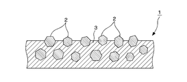
- FIG. 1 It is a schematic sectional drawing which shows an example of a structure of a fixed abrasive grindstone (diamond pad). It is a schematic diagram for demonstrating the state at the time of a grinding process. It is a figure which shows an example of the measurement location of the distance between average abrasive grains on a fixed abrasive grindstone. It is a figure which shows the relationship between the distance between average abrasive grains, and a grinding rate.
- a glass substrate for a magnetic disk is usually manufactured through a shape processing step, a grinding step, an end surface polishing step, a main surface polishing step, a chemical strengthening step, and the like.
- a glass substrate is obtained by cutting into a predetermined size from a sheet-like glass produced by a float method or a downdraw method.
- a sheet-like plate glass produced by pressing from molten glass may be used.
- the present invention is suitable when a glass substrate having a mirror-like main surface is used at the start of grinding.
- this glass substrate is ground to improve dimensional accuracy and shape accuracy.
- a main surface of the glass substrate is generally ground using a double-side grinding apparatus and using hard abrasive grains such as diamond.
- the present invention relates to the improvement of this grinding process.
- the grinding process in the present invention is a grinding process using, for example, fixed abrasive grains containing diamond particles.
- a carrier is placed between upper and lower surface plates on which diamond pads are bonded as fixed abrasive grains. Both the main surfaces of the glass substrate are ground at the same time by closely moving the glass substrate and the upper and lower surface plates while closely holding the held glass substrate and sandwiching the glass substrate with the upper and lower surface plates with a predetermined pressure. .
- a lubricating liquid (coolant) is supplied to cool the working surface or to promote the processing.
- a diamond pad can be used, and an outline of the configuration is shown in FIG.
- the diamond pad 1 shown in FIG. 1 is an abrasive aggregate (collected abrasive grains or aggregated abrasive grains) in which a plurality of diamond particles 4 (see FIG. 2) are hardened with a binder such as glass, ceramic, metal, or resin. 2) is fixed using a support material 3 such as a resin (for example, acrylic resin).
- a resin for example, acrylic resin
- a diamond pad in which grooves are formed in a resin layer after a resin layer containing diamond abrasive aggregates is formed on a sheet may be used.
- abrasive aggregates for example, single diamond particles may be dispersed as they are on a support material.
- the aggregates having different particle diameters (average particle diameter) and abrasive density.
- fixed abrasive grains or simply abrasive grains, unless otherwise specified, it means the above-mentioned aggregate, and the average particle diameter of fixed abrasive grains, and abrasive grains
- density it shall mean the average particle diameter of the said aggregate, and an abrasive grain density.
- the grinding process in the present invention is a grinding process in which the main surface of the glass substrate is ground using a lubricating liquid and a surface plate in which a fixed abrasive grindstone is provided on the grinding surface, as in the configuration 1 described above.
- the fixed abrasive whetstone includes fixed abrasive contained in a support material, and an average inter-abrasive distance of the fixed abrasive on the grinding surface of the fixed abrasive whetstone and the fixed abrasive whetstone Preliminarily obtained a correlation with the processing speed when grinding the glass substrate, and select a fixed abrasive grindstone having an average inter-abrasive distance to obtain a desired processing speed based on the obtained correlation, The grinding process is performed using the selected fixed abrasive grindstone.
- the processing speed varies depending on the dispersion state of the abrasive grains, and stable grinding performance is achieved. It was not obtained.
- the current performance is that the grinding performance of a fixed-abrasive grindstone such as a diamond pad cannot be understood unless it is actually used.
- the reason for this is, for example, that the physical properties of the abrasive grains and the resin differ greatly depending on the material, so that it is relatively difficult to uniformly disperse them in the manufacturing process.
- the inventor of the present invention grinds an average inter-abrasive distance between fixed abrasive grains on a grinding surface of a fixed abrasive grindstone and grinds a glass substrate using the fixed abrasive grindstone. It has been found that there is a correlation between the machining speed and the processing speed. Therefore, such a correlation is obtained in advance, and a fixed abrasive wheel having an average inter-abrasive distance that provides a desired processing speed is selected based on the obtained correlation.
- a fixed abrasive wheel having this predetermined average inter-abrasive distance by selecting and using a fixed abrasive wheel having this predetermined average inter-abrasive distance, a high processing speed and stable grinding performance can be obtained, so that the processing speed is increased and stable grinding is performed. Is possible. In short, it is possible to stably and increase the processing speed in grinding by using a fixed abrasive wheel in which the distance between the fixed abrasives is appropriately controlled on the surface of the fixed abrasive wheel (grinding surface). is there.
- the present invention is particularly suitable for grinding a glass substrate having a mirror-like main surface.
- the said measurement range is an example, Comprising: When determining a measurement range, it determines so that 15 or more fixed abrasives may be contained in one measurement range. Although details will be described later, the average inter-abrasive distance is obtained by calculating and averaging a plurality of values, so that the average inter-abrasive distance can be stably calculated. If the set measurement range does not include 15 or more fixed abrasive grains, another measurement range is set. In addition, the fixed abrasive grains counted at this time are larger than the average particle diameter (D50) of the fixed abrasive grains when the diameter is obtained by approximating the circle among the fixed abrasive grains observed within the measurement range. Count the number of things only.
- D50 average particle diameter
- the average particle diameter of the fixed abrasive may be obtained in advance.
- the reason for counting by focusing on fixed abrasive grains having an average particle diameter or larger is that other abrasive grains contribute very little to the grinding process. That is, when the fixed abrasive grains are mostly buried in the grindstone and the amount of protrusion from the grinding surface is small, or the abrasive grains having a small size themselves contribute very little to the processing. If these are also counted, there is a possibility that the correlation with the processing rate cannot be obtained.
- the average particle diameter (D50) is 50% when the cumulative curve is determined with the total volume of the powder population in the particle size distribution measured by the laser diffraction method as 100%.
- the particle size hereinafter referred to as “cumulative average particle size (50% diameter)”.
- the cumulative average particle diameter (50% diameter) is a value that can be measured using a particle diameter / particle size distribution measuring device.
- the present invention in order to improve the reliability of the measurement result, it is desirable to provide a plurality of measurement locations.
- two measurement regions are provided for each of the inner circumferential portion, the middle circumferential portion, and the outer circumferential portion on the grinding surface of one annular shaped fixed abrasive grindstone.
- the two locations are preferably provided so as to be point-contrast with respect to the center of the fixed abrasive wheel.
- the said measurement location is provided about each of the upper and lower surface plates.
- the fixed abrasive is preferably a diamond abrasive aggregate.
- the average particle diameter (D50) of one diamond abrasive grain is preferably about 1 to 10 ⁇ m.
- the average particle diameter (D50) of the diamond abrasive agglomerates is preferably about 15 ⁇ m to 50 ⁇ m. If the average particle diameter of the diamond abrasive grains is less than the above, the cutting with respect to the mirror-like glass substrate becomes shallow, and there is a possibility that the grinding of the glass substrate is difficult to proceed. On the other hand, if the average particle diameter of the diamond abrasive grains exceeds the above, the roughness of the finish becomes rough, so there is a possibility that the machining allowance load in the subsequent process becomes large.
- a desired processing speed is obtained.
- a fixed abrasive grindstone having an average inter-abrasive distance is selected, and the average inter-abrasive distance is preferably in the range of 80 ⁇ m to 200 ⁇ m, for example. If the average inter-abrasive distance is too small, not only does the correlation with the processing speed disappear, but the average inter-abrasive distance is too close, and the processing speed may be reduced, resulting in a significant deterioration in productivity. On the other hand, even if the average inter-abrasive distance is too far, there is no correlation with the processing speed, and the processing speed decreases.
- the density of the fixed abrasive contained in the support material on the grinding surface is preferably in the range of about 10 to 40 pieces / mm 2 .
- the content of the fixed abrasive in the fixed abrasive grindstone is preferably 5 to 80% by volume. If the content of the fixed abrasive deviates from the above range (both excess and deficiency), both may increase the processing time and increase the cost.
- the load during processing is preferably 50 g / cm 2 to 200 g / cm 2 . If it is smaller than this range, the processing speed becomes too low, and the productivity may be deteriorated. If it is larger than this range, scratches may occur.
- a diamond load is applied to the glass substrate surface so that a higher load is applied to the glass surface than during normal grinding. Is preferred. The higher the load, the deeper the cutting depth of the abrasive grains, the rougher the glass surface can be made (roughened).
- FIG. 2 is a schematic diagram for explaining a state at the time of grinding, and shows a state in which the aggregate 2 of diamond abrasive grains 4 bites into the glass substrate 10 and is ground (expected view).
- the load at the start of processing or at the initial stage of processing is preferably in the range of 130 to 200 g / cm 2 , for example. If the load is less than 130 g / cm 2, the time during which grinding cannot be performed (dead time) cannot be sufficiently shortened, and the processing speed is reduced. On the other hand, if the load is larger than 200 g / cm 2, the depth of cut by the abrasive grains becomes too deep and a lot of scratches are generated, so that it is necessary to increase the allowance for subsequent processing and subsequent polishing steps. The time will be longer.
- the load at the stage after the glass surface is roughened is preferably in the range of 50 to 120 g / cm 2 , for example. By adjusting the grinding conditions, the surface roughness of the processed surface can be kept low.
- the processing speed in the grinding processing is preferably in the range of about 50 to 160 ⁇ m / min. Therefore, it is desirable to select a fixed abrasive grindstone having an average inter-abrasive distance at which such a processing speed can be obtained from the above correlation.
- the surface of the glass substrate put into the grinding process is in a mirror state, and the surface roughness is, for example, Ra in the range of 0.001 to 0.01 ⁇ m.
- the surface roughness of the glass substrate after completion of the grinding process is preferably finished in the range of 0.080 to 0.130 ⁇ m in Ra.
- the plate thickness of the original material before being put into the grinding process is changed due to the design change of the process, the target plate thickness after the processing is changed, or the original material varies.
- the machining speed can be controlled, so that the grinding time can be made constant.
- the movement of the glass substrate can be carried out systematically without waste such as time loss in the process chain from pretreatment to grinding treatment to post-treatment. Can be dramatically improved. This is extremely effective when mass production such as the manufacture of a glass substrate for a magnetic disk is assumed.
- the glass constituting the glass substrate is preferably an amorphous aluminosilicate glass.
- a glass substrate can be finished to a smooth mirror surface by mirror polishing the surface, and the strength after processing is good.
- aluminosilicate glass include SiO2 58 to 66%, Al2O3 13 to 19%, Li2O 3 to 4.5%, Na2O 6 to 13%, K2O 0 to 5%, and MgO, expressed in weight%.
- An amorphous aluminosilicate glass having a composition of 0 to 3.5% and CaO of 0 to 7% can be used.
- a glass containing SiO2 as a main component and containing 20% by weight or less of Al2O3 is preferable.
- glass containing SiO2 as a main component and containing Al2O3 or less by 15% by weight or less.
- SiO2 is 62 wt% to 75 wt%
- Al2 O3 is 5 wt% to 15 wt%
- Li2 O is 4 wt% to 10 wt%
- Na2 O is 4 wt% to 12 wt%
- the weight ratio of Na 2 O / ZrO 2 is 0.5 to 2.0
- the weight ratio of Al 2 O 3 / ZrO 2 is 0.4 to 2.5 It is possible to use amorphous aluminosilicate glass that does not contain phosphorous oxide.
- the heat-resistant glass used for the next generation heat-assisted magnetic recording magnetic disk is, for example, 50 to 75% of SiO2, 0 to 5% of Al2O3, and 0 to 2% of BaO in terms of mol%. , Li2O 0-3%, ZnO 0-5%, Na2O and K2O 3-15% in total, MgO, CaO, SrO and BaO 14-35% in total, ZrO2, TiO2, La2O3, Y2O3, Yb2O3 , Ta2O5, Nb2O5 and HfO2 in total 2 to 9%, the molar ratio [(MgO + CaO) / (MgO + CaO + SrO + BaO)] is in the range of 0.85 to 1, and the molar ratio [Al2O3 / (MgO + CaO)] is 0.
- Glass having a range of ⁇ 0.30 can be preferably used. Further, SiO2 is 56 to 75 mol%, Al2O3 is 1 to 9 mol%, a total of 6 to 15 mol% of alkali metal oxides selected from the group consisting of Li2O, Na2O and K2O, and a group consisting of MgO, CaO and SrO 10 to 30 mol% in total of alkaline earth metal oxides selected from the group consisting of oxides selected from the group consisting of ZrO2, TiO2, Y2O3, La2O3, Gd2O3, Nb2O5 and Ta2O5 in total exceeding 0% and not more than 10 mol% Including glass.
- the content of Al2O3 in the glass composition is preferably 15% by weight or less. Furthermore, it is more preferable that the content of Al2O3 is 5 mol% or less.
- mirror polishing is performed to obtain a highly accurate plane.
- the processing surface roughness can be reduced, so the amount removed in the subsequent mirror polishing process Therefore, the processing load is reduced and the processing cost can be reduced.
- a polishing pad of a polisher such as polyurethane while supplying a slurry (polishing liquid) containing a metal oxide abrasive such as cerium oxide or colloidal silica.
- a slurry polishing liquid
- a metal oxide abrasive such as cerium oxide or colloidal silica.
- a glass substrate having high smoothness is obtained, for example, by polishing with a cerium oxide-based abrasive (first polishing process) and then with final polishing (mirror polishing) (second polishing process) using colloidal silica abrasive grains. It is possible.
- the surface of the glass substrate after mirror polishing is preferably a mirror surface having an arithmetic average surface roughness Ra of 0.2 nm or less, more preferably 0.13 nm or less.
- the arithmetic average roughness Ra is a roughness calculated in accordance with Japanese Industrial Standard (JIS) B0601.
- the surface roughness (the arithmetic average roughness Ra) is preferably practically the surface roughness obtained when measured with an atomic force microscope (AFM).
- chemical strengthening treatment may be performed.
- a method of the chemical strengthening treatment for example, a low-temperature ion exchange method in which ion exchange is performed in a temperature range not exceeding the glass transition temperature is preferable. Since the chemically strengthened glass substrate is excellent in impact resistance, it is particularly preferable for mounting on a HDD for mobile use, for example.
- the chemical strengthening salt alkali metal nitrates such as potassium nitrate and sodium nitrate can be preferably used.
- the present invention also provides a method for manufacturing a magnetic disk using the above glass substrate for a magnetic disk.
- the magnetic disk is produced by forming at least a magnetic recording layer (magnetic layer) on the magnetic disk glass substrate according to the present invention.
- a magnetic recording layer magnetic layer
- a hexagonal CoCrPt-based or CoPt-based ferromagnetic alloy having a large anisotropic magnetic field can be used.
- a method of forming the magnetic layer it is preferable to use a method of forming a magnetic layer on a glass substrate by a sputtering method, for example, a DC magnetron sputtering method.
- a protective layer and a lubricating layer may be formed on the magnetic recording layer.
- the protective layer an amorphous carbon-based protective layer is suitable.
- a lubricating layer a lubricant having a functional group at the end of the main chain of the perfluoropolyether compound can be used.
- Substrate preparation process A large plate glass made of aluminosilicate glass having a thickness of 1 mm manufactured by the float process was prepared, and cut into 70 mm x 70 mm square pieces using a diamond cutter. Subsequently, it processed into the disk shape of outer diameter 65mm and internal diameter 20mm using the diamond cutter.
- the aluminosilicate glass includes SiO 2 58 to 66%, Al 2 O 3 13 to 19%, Li 2 O 3 to 4.5%, Na 2 O 6 to 13%, K 2 O 0 to 5%, MgO 0 A chemically strengthening glass containing ⁇ 3.5% and CaO 0-7% was used.
- This main surface grinding processing is performed by using a double-sided grinding machine and setting a glass substrate held by a carrier between upper and lower surface plates on which diamond pads are attached as fixed abrasive wheels. It was.
- the glass substrate held by the carrier is brought into close contact between the upper and lower surface plates to which the diamond pad is attached, and this carrier is engaged with the sun gear (sun gear) and the internal gear (internal gear), The glass substrate is sandwiched between upper and lower surface plates. After that, by supplying and rotating a grinding liquid between the diamond pad and the grinding surface of the glass substrate, the glass substrate revolves while rotating on the surface plate to simultaneously grind both surfaces.
- the diamond pad includes fixed abrasive grains composed of aggregates of diamond abrasive grains.
- the average particle diameter of the aggregates is about 25 ⁇ m, and the average grain diameter (D50) of the diamond abrasive grains is about 2.5 ⁇ m.
- a plurality of diamond pads were prepared. Moreover, it carried out using the lubricating liquid. Moreover, the rotation speed of the surface plate and the load on the glass substrate were adjusted as appropriate.
- the average inter-abrasive distance of the fixed abrasive grains in each diamond pad was determined by the above-described method, and 10,000 diamonds were processed using each diamond pad. Then, a correlation between the inter-abrasive distance (average inter-abrasive distance) of each diamond pad and the processing speed (grinding rate) when the glass substrate was ground using the diamond pad was determined. The results are shown in Tables 1 and 2 below. In Table 1, the value of the abrasive density is also shown. 4 is a graph showing the relationship between the inter-abrasive distance (average inter-abrasive distance) and the processing speed (grinding rate) based on Tables 1 and 2. The grinding speed is a value obtained by dividing the total grinding thickness by the total machining time.
- a first polishing process for removing scratches and distortions remaining in the above-described grinding process was performed using a double-side polishing apparatus having the same configuration as the grinding process. Specifically, a hard polisher (hard foamed urethane) was used as the polisher, and the first polishing step was performed.
- the polishing liquid was pure water in which cerium oxide was dispersed as an abrasive, and the load and polishing time were appropriately set.
- the glass substrate after the first polishing step was subjected to ultrasonic cleaning and dried.
- Chemical strengthening step chemical strengthening was performed on the glass substrate after the cleaning.
- a chemical strengthening solution in which potassium nitrate and sodium nitrate were mixed was prepared, and the cleaned and dried glass substrate was immersed in a solution obtained by heating and melting the chemical strengthening solution to perform chemical strengthening treatment. .
- a glass substrate was obtained. Further, the main surface of the glass substrate was mirror-like, and when examined using a laser-type surface defect analyzer, surface defects such as abnormal protrusions and scratches were not observed.
- the obtained glass substrate had an outer diameter of 65 mm, an inner diameter of 20 mm, and a plate thickness of 0.635 mm.
- the average particle diameter (D50) of the diamond abrasive grains is 1.5 ⁇ m and the average particle diameter (D50) of the aggregates is 15 ⁇ m
- the average particle diameter (D50) of the diamond abrasive grains is 9 ⁇ m and the average particles of the aggregates
- the diameter (D50) was 50 ⁇ m
- the same investigation was conducted, and a good correlation with the grinding rate was observed when the average inter-abrasive distance was in the range of 80 ⁇ m to 200 ⁇ m.
- the following film forming steps were performed on the magnetic disk glass substrate obtained in the above example to obtain a magnetic disk for perpendicular magnetic recording. That is, an adhesion layer made of a Ti-based alloy thin film, a soft magnetic layer made of a CoTaZr alloy thin film, an underlayer made of a Ru thin film, a perpendicular magnetic recording layer made of a CoCrPt alloy, a protective layer, and a lubricating layer are sequentially formed on the glass substrate. Filmed. As the protective layer, a hydrogenated carbon layer was formed. The lubricating layer was formed by dipping a liquid lubricant of alcohol-modified perfluoropolyether.
- the obtained magnetic disk was installed in an HDD equipped with a DFH head, and a load / unload durability test was conducted for one month while operating the DFH function in a high temperature and high humidity environment of 80 ° C. and 80% RH. There were no particular obstacles and good results were obtained.
- Diamond pad Abrasive aggregate (concentrated abrasive grains) 3 Support material 4 Diamond particle 10 Glass substrate
Landscapes
- Engineering & Computer Science (AREA)
- Manufacturing & Machinery (AREA)
- Manufacturing Of Magnetic Record Carriers (AREA)
Abstract
Description
また、ガラス基板表面は磁気ヘッドの浮上高さを極力下げることができるように、高精度に研磨して高記録密度化を実現している。近年、HDDの更なる大記録容量化、低価格化の要求は増すばかりであり、これを実現するためには、磁気ディスク用ガラス基板においても更なる高品質化、低コスト化が必要になってきている。
この研削加工工程の終了後は、高精度な平面を得るための鏡面研磨加工を行っている。
従来、固定砥粒による研削加工において、研削加工速度を高めようとする場合、固定砥粒の密度を高めることが行われていた(特許文献2参照)。しかし、本発明者の検討によると、固定砥粒の密度を高めただけでは加工速度を増加できない場合があることが判明した。また、同じ砥粒密度のダイヤモンドパッドを使用しても加工速度にバラツキがあることが判明した。
すなわち、上記課題を解決するため、本発明は以下の構成を有する。
潤滑液と、固定砥粒砥石が研削面に配備された定盤とを用いてガラス基板の主表面を研削する研削加工処理を含む磁気ディスク用ガラス基板の製造方法であって、前記固定砥粒砥石は、支持材中に含有させた固定砥粒を含み、前記固定砥粒砥石の研削面における前記固定砥粒の平均砥粒間距離と、当該固定砥粒砥石を用いて前記ガラス基板を研削加工した場合の加工速度との相関関係を予め求めておき、この求めた相関関係に基づき所望の加工速度が得られる平均砥粒間距離を有する固定砥粒砥石を選択し、この選択した固定砥粒砥石を用いて前記研削加工処理を行うことを特徴とする磁気ディスク用ガラス基板の製造方法。
潤滑液と、固定砥粒砥石が研削面に配備された定盤とを用いてガラス基板の主表面を研削する研削加工処理を含む磁気ディスク用ガラス基板の製造方法であって、前記固定砥粒砥石は、支持材中に含有させた固定砥粒を含み、前記固定砥粒砥石の研削面における前記固定砥粒の平均砥粒間距離は80μm~200μmであることを特徴とする磁気ディスク用ガラス基板の製造方法。
前記平均砥粒間距離が、80μm~200μmであることを特徴とする構成1に記載の磁気ディスク用ガラス基板の製造方法。
(構成4)
前記固定砥粒の平均粒子径が、15μm~50μmであることを特徴とする構成1乃至3のいずれかに記載の磁気ディスク用ガラス基板の製造方法。
前記固定砥粒はダイヤモンド砥粒粒子を含むことを特徴とする構成1乃至4に記載の磁気ディスク用ガラス基板の製造方法。
(構成6)
前記固定砥粒は、砥粒粒子又は、複数の砥粒粒子がバインダーで固められた砥粒凝集体であることを特徴とする構成1乃至5に記載の磁気ディスク用ガラス基板の製造方法。
前記ガラス基板は、研削加工開始時に主表面が鏡面状のガラス基板であることを特徴とする構成1乃至6に記載の磁気ディスク用ガラス基板の製造方法。
(構成8)
加工荷重が、50g/cm2~200g/cm2であることを特徴とする構成1乃至7に記載の磁気ディスク用ガラス基板の製造方法。
構成1乃至8のいずれかに記載の磁気ディスク用ガラス基板の製造方法により製造された磁気ディスク用ガラス基板上に、少なくとも磁気記録層を形成することを特徴とする磁気ディスクの製造方法。
磁気ディスク用ガラス基板は、通常、形状加工工程、研削工程、端面研磨工程、主表面研磨工程、化学強化工程、等を経て製造される。
本発明の磁気ディスク用ガラス基板の製造方法においては、フロート法やダウンドロー法で製造されたシート状ガラスから所定の大きさに切り出してガラス基板を得る。また、これ以外に、溶融ガラスからプレスで作製したシート状板ガラスを用いてもよい。本発明は、研削加工開始時に主表面が鏡面状のガラス基板を使用する場合に好適である。
要するに、固定砥粒砥石表面(研削加工面)において、固定砥粒間の距離が適切に制御されている固定砥粒砥石を用いることによって、研削加工における加工速度を安定に且つ高めることが可能である。また、本発明は、特に主表面が鏡面状のガラス基板に対する研削加工に好適である。
(1)例えばダイヤモンドパッド等の固定砥粒砥石の表面(研削面)を走査型電子顕微鏡(SEM)を用いて観察する。
(2)本発明においては、1.25mm×0.825mm(=1.03mm2)の矩形領域を測定範囲とする。
もし、設定した測定範囲に15個以上の固定砥粒が含まれていない場合には、別の測定範囲を設定する。なお、このときカウントする固定砥粒は、測定範囲内で観察された固定砥粒のうち、円で近似して直径を求めたときに当該直径が固定砥粒の平均粒子径(D50)より大きなもののみについて数をカウントする。固定砥粒の平均粒子径は予め求めておけばよい。平均粒子径以上の固定砥粒に着目して集計する理由は、それ以外の砥粒は研削加工への寄与が極めて少ないためである。すなわち、固定砥粒の大部分が砥石に埋もれて研削面からの突出量が小さいものや、砥粒の大きさ自体が小さいものは、加工への寄与が極めて少ないからである。これらもカウントしてしまうと、加工レートとの相関が得られない恐れがある。
また、固定砥粒砥石における固定砥粒の含有量は、5~80体積%であることが好ましい。固定砥粒の含有量が上記範囲を逸脱(超過及び不足のいずれも)すると、いずれも加工時間の増大を招いてコスト高となる場合がある。
なお、鏡面状のガラス基板表面を固定砥粒砥石で研削加工する場合、まず、例えばダイヤモンド砥粒をガラス基板表面に食い込ませるためガラス表面に対して通常の研削加工時よりも高い荷重負荷をかけることが好適である。高い負荷はそれだけ砥粒の切り込み深さが深くなるため、ガラス表面の粗さを粗くさせる(粗面化する)ことができる。
また、ガラス表面が粗面化された後の段階における荷重は、例えば50~120g/cm2の範囲とすることが好ましい。研削加工の条件を調節することで加工面の表面粗さを低く抑えることも可能になる。
また、本発明においては、研削加工処理終了後のガラス基板の表面粗さが、Raで0.080~0.130μmの範囲に仕上がることが好ましい。このように仕上がりの粗さを低く抑えることで、後の工程の加工負荷を減らすことができる。
また、SiO2 を主成分としてAl2O3を20重量%以下含むガラスが好ましい。さらに、SiO2を主成分としてAl2O3を15重量%以下含むガラスとするとより好ましい。具体的には、SiO2を62重量%以上75重量%以下、Al2O3 を5重量%以上15重量%以下、Li2Oを4重量%以上10重量%以下、Na2Oを4重量%以上12重量%以下、ZrO2 を5.5重量%以上15重量%以下、主成分として含有するとともに、Na2O/ZrO2の重量比が0.5以上2.0以下、Al2O3 /ZrO2 の重量比が0.4以上2.5以下であるリン酸化物を含まないアモルファスのアルミノシリケートガラスを用いることができる。
また、SiO2を56~75モル%、Al2O3を1~9モル%、Li2O、Na2OおよびK2Oからなる群から選ばれるアルカリ金属酸化物を合計で6~15モル%、MgO、CaOおよびSrOからなる群から選ばれるアルカリ土類金属酸化物を合計で10~30モル%、ZrO2、TiO2、Y2O3、La2O3、Gd2O3、Nb2O5およびTa2O5からなる群から選ばれる酸化物を合計で0%超かつ10モル%以下、含むガラスであってもよい。
本発明において、ガラス組成におけるAl2O3の含有量が15重量%以下であると好ましい。さらには、Al2O3の含有量が5モル%以下であるとなお好ましい。
本発明においては、研削加工において、従来の遊離砥粒方式に対し、固定砥粒方式を適用したことにより、加工表面粗さの低下が可能となったため、後の鏡面研磨加工工程での除去量が少なくて済み、加工負荷が低減され、加工コストの削減が可能になる。
また、本発明において表面粗さ(上記算術平均粗さRa)は、原子間力顕微鏡(AFM)で測定したときに得られる表面形状の表面粗さとすることが実用上好ましい。
本発明において磁気ディスクは、本発明による磁気ディスク用ガラス基板の上に少なくとも磁気記録層(磁性層)を形成して製造される。磁性層の材料としては、異方性磁界の大きな六方晶系であるCoCrPt系やCoPt系強磁性合金を用いることができる。磁性層の形成方法としてはスパッタリング法、例えばDCマグネトロンスパッタリング法によりガラス基板の上に磁性層を成膜する方法を用いることが好適である。
本発明によって得られる磁気ディスク用ガラス基板を利用することにより、信頼性の高い磁気ディスクを得ることができる。
(実施例)
以下の(1)基板準備工程、(2)形状加工工程、(3)端面研磨工程、(4)主表面研削加工処理、(5)主表面研磨工程(第1研磨工程)、(6)化学強化工程、(7)主表面研磨工程(第2研磨工程)を経て本実施例の磁気ディスク用ガラス基板を製造した。
フロート法により製造された厚さ1mmのアルミノシリケートガラスからなる大板ガラスを準備し、70mm×70mmの正方形の小片にダイヤモンドカッターを用いて裁断した。次いで、ダイヤモンドカッターを用いて、外径65mm、内径20mmの円盤形状に加工した。このアルミノシリケートガラスとしては、SiO2 58~66%、Al2O3 13~19%、Li2O3~ 4.5%、Na2O6~13%、K2O 0~ 5%、MgO 0~ 3.5%、CaO 0~7%を含有する化学強化用ガラスを使用した。
次に、ダイヤモンド砥石を用いてガラス基板の中央部分に孔を空けると共に、外周端面および内周端面に所定の面取り加工を施した。
(3)端面研磨工程
次いで、ブラシ研磨により、ガラス基板を回転させながらガラス基板の端面(内周、外周)を研磨した。
この主表面研削加工処理は両面研削装置を用い、固定砥粒砥石としてダイヤモンドパッドが貼り付けられた上下定盤の間にキャリアにより保持したガラス基板をセットして行なった。両面研削装置においては、ダイヤモンドパッドが貼り付けられた上下定盤の間にキャリアにより保持したガラス基板を密着させ、このキャリアを太陽歯車(サンギア)と内歯歯車(インターナルギア)とに噛合させ、上記ガラス基板を上下定盤によって挟圧する。その後、ダイヤモンドパッドとガラス基板の研削面との間に研削液を供給して回転させることによって、ガラス基板が定盤上で自転しながら公転して両面を同時に研削加工するものである。
ダイヤモンドパッドは、ダイヤモンド砥粒の凝集体からなる固定砥粒を含み、凝集体の平均粒子径は約25μm、ダイヤモンド砥粒の平均粒径(D50)は約2.5μmであった。このダイヤモンドパッドを複数枚準備した。また、潤滑液を使用しながら行った。また、定盤の回転数、ガラス基板への荷重は、適宜調整して行った。
そして、各ダイヤモンドパッドの砥粒間距離(平均砥粒間距離)と、当該ダイヤモンドパッドを用いてガラス基板を研削加工した場合の加工速度(研削レート)との相関関係を求めた。結果を下記表1及び表2に示した。表1においては、砥粒密度の値も併せて示した。また、表1及び表2に基づき、砥粒間距離(平均砥粒間距離)と加工速度(研削レート)との関係をグラフにしたものを図4に示した。
なお、上記研削加工速度は、全研削厚みを全加工時間で除した値である。
次に、上述した研削加工で残留した傷や歪みを除去するための第1研磨工程を、研削工程と同様の構成の両面研磨装置を用いて行なった。具体的には、ポリシャとして硬質ポリシャ(硬質発泡ウレタン)を用い、第1研磨工程を実施した。研磨液としては酸化セリウムを研磨剤として分散した純水とし、荷重、研磨時間は適宜設定した。上記第1研磨工程を終えたガラス基板を超音波洗浄し、乾燥した。
次に、上記洗浄を終えたガラス基板に化学強化を施した。化学強化は硝酸カリウムと硝酸ナトリウムの混合した化学強化液を用意し、この化学強化溶液を加熱して溶融させた溶解液中に上記洗浄・乾燥済みのガラス基板を浸漬して化学強化処理を行なった。
次いで上記の第1研磨工程で使用したものと同じ両面研磨装置を用い、ポリシャを軟質ポリシャ(スウェード)の研磨パッド(発泡ポリウレタン製)に替えて第2研磨工程を実施した。この第2研磨工程は、上述した第1研磨工程で得られた平坦な表面を維持しつつ、例えばガラス基板主表面の表面粗さをRaで0.2nm程度以下の平滑な鏡面に仕上げるための鏡面研磨加工である。研磨液としてはコロイダルシリカを分散した純水とし、荷重、研磨時間は適宜設定した。上記第2研磨工程を終えたガラス基板を超音波洗浄し、乾燥した。

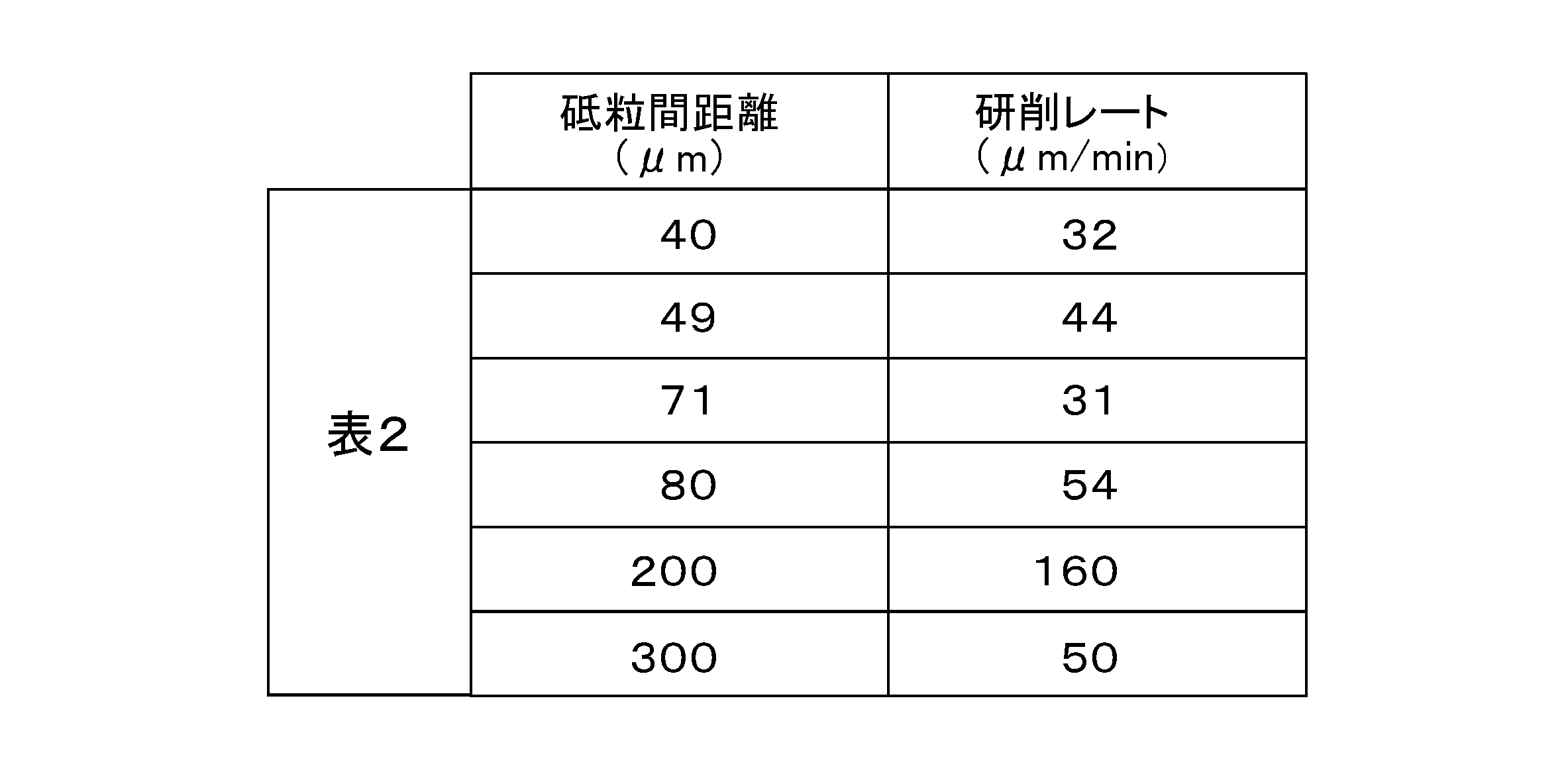
加工速度(研削レート)は砥粒密度との関係性は低く,砥粒間距離(平均砥粒間距離)との相関が高い。特に、砥粒間距離(平均砥粒間距離)が、80μm~200μmの範囲で研削レートと良い相関がみられる(図4参照)。
したがって、この求めた相関関係に基づき所望の加工速度が得られる砥粒間距離を有する固定砥粒砥石を選択して用いることにより、加工速度が高く且つ安定した研削性能が得られるため、加工速度を高めて安定した研削加工を行うことが可能である。
なお、ダイヤモンド砥粒の平均粒径(D50)が1.5μmで凝集体の平均粒子径(D50)が15μmの場合と、ダイヤモンド砥粒の平均粒径(D50)が9μmで凝集体の平均粒子径(D50)が50μmの場合についても同様に調査したところ、平均砥粒間距離が80μm~200μmの範囲で研削レートと良い相関がみられた。
上記実施例で得られた磁気ディスク用ガラス基板に以下の成膜工程を施して、垂直磁気記録用磁気ディスクを得た。
すなわち、上記ガラス基板上に、Ti系合金薄膜からなる付着層、CoTaZr合金薄膜からなる軟磁性層、Ru薄膜からなる下地層、CoCrPt合金からなる垂直磁気記録層、保護層、潤滑層を順次成膜した。保護層は、水素化カーボン層を成膜した。また、潤滑層は、アルコール変性パーフルオロポリエーテルの液体潤滑剤をディップ法により形成した。
得られた磁気ディスクについて、DFHヘッドを備えたHDDに組み込み、80℃かつ80%RHの高温高湿環境下においてDFH機能を作動させつつ1ヶ月間のロードアンロード耐久性試験を行ったところ、特に障害も無く、良好な結果が得られた。
2 砥粒凝集体(集結砥粒)
3 支持材
4 ダイヤモンド粒子
10 ガラス基板
Claims (9)
- 潤滑液と、固定砥粒砥石が研削面に配備された定盤とを用いてガラス基板の主表面を研削する研削加工処理を含む磁気ディスク用ガラス基板の製造方法であって、
前記固定砥粒砥石は、支持材中に含有させた固定砥粒を含み、
前記固定砥粒砥石の研削面における前記固定砥粒の平均砥粒間距離と、当該固定砥粒砥石を用いて前記ガラス基板を研削加工した場合の加工速度との相関関係を予め求めておき、
この求めた相関関係に基づき所望の加工速度が得られる平均砥粒間距離を有する固定砥粒砥石を選択し、この選択した固定砥粒砥石を用いて前記研削加工処理を行うことを特徴とする磁気ディスク用ガラス基板の製造方法。 - 潤滑液と、固定砥粒砥石が研削面に配備された定盤とを用いてガラス基板の主表面を研削する研削加工処理を含む磁気ディスク用ガラス基板の製造方法であって、
前記固定砥粒砥石は、支持材中に含有させた固定砥粒を含み、
前記固定砥粒砥石の研削面における前記固定砥粒の平均砥粒間距離は80μm~200μmであることを特徴とする磁気ディスク用ガラス基板の製造方法。 - 前記平均砥粒間距離が、80μm~200μmであることを特徴とする請求項1に記載の磁気ディスク用ガラス基板の製造方法。
- 前記固定砥粒の平均粒子径が、15μm~50μmであることを特徴とする請求項1乃至3のいずれかに記載の磁気ディスク用ガラス基板の製造方法。
- 前記固定砥粒はダイヤモンド砥粒粒子を含むことを特徴とする請求項1乃至4に記載の磁気ディスク用ガラス基板の製造方法。
- 前記固定砥粒は、砥粒粒子又は、複数の砥粒粒子がバインダーで固められた砥粒凝集体であることを特徴とする請求項1乃至5に記載の磁気ディスク用ガラス基板の製造方法。
- 前記ガラス基板は、研削加工開始時に主表面が鏡面状のガラス基板であることを特徴とする請求項1乃至6に記載の磁気ディスク用ガラス基板の製造方法。
- 加工荷重が、50g/cm2~200g/cm2であることを特徴とする請求項1乃至7に記載の磁気ディスク用ガラス基板の製造方法。
- 請求項1乃至8のいずれかに記載の磁気ディスク用ガラス基板の製造方法により製造された磁気ディスク用ガラス基板上に、少なくとも磁気記録層を形成することを特徴とする磁気ディスクの製造方法。
Priority Applications (4)
| Application Number | Priority Date | Filing Date | Title |
|---|---|---|---|
| MYPI2016701095A MY190012A (en) | 2013-09-30 | 2014-09-30 | Method for manufacturing magnetic-disk glass substrate and method for manufacturing magnetic disk |
| SG11201602381TA SG11201602381TA (en) | 2013-09-30 | 2014-09-30 | Method for manufacturing magnetic-disk glass substrate and method for manufacturing magnetic disk |
| JP2015539472A JP6193388B2 (ja) | 2013-09-30 | 2014-09-30 | 磁気ディスク用ガラス基板の製造方法、ガラス基板の製造方法及び磁気ディスクの製造方法、並びに固定砥粒砥石 |
| CN201480053020.3A CN105580077B (zh) | 2013-09-30 | 2014-09-30 | 磁盘用玻璃基板的制造方法以及磁盘的制造方法 |
Applications Claiming Priority (2)
| Application Number | Priority Date | Filing Date | Title |
|---|---|---|---|
| JP2013203990 | 2013-09-30 | ||
| JP2013-203990 | 2013-09-30 |
Publications (1)
| Publication Number | Publication Date |
|---|---|
| WO2015046596A1 true WO2015046596A1 (ja) | 2015-04-02 |
Family
ID=52743717
Family Applications (1)
| Application Number | Title | Priority Date | Filing Date |
|---|---|---|---|
| PCT/JP2014/076187 Ceased WO2015046596A1 (ja) | 2013-09-30 | 2014-09-30 | 磁気ディスク用ガラス基板の製造方法及び磁気ディスクの製造方法 |
Country Status (5)
| Country | Link |
|---|---|
| JP (1) | JP6193388B2 (ja) |
| CN (2) | CN111048122B (ja) |
| MY (1) | MY190012A (ja) |
| SG (1) | SG11201602381TA (ja) |
| WO (1) | WO2015046596A1 (ja) |
Citations (3)
| Publication number | Priority date | Publication date | Assignee | Title |
|---|---|---|---|---|
| JPH09216151A (ja) * | 1996-02-13 | 1997-08-19 | Kao Corp | 表面加工基板の製造方法 |
| JP2012027976A (ja) * | 2010-07-22 | 2012-02-09 | Asahi Glass Co Ltd | 磁気記録媒体用ガラス基板の製造方法 |
| JP2013071212A (ja) * | 2011-09-28 | 2013-04-22 | Hoya Corp | 基板の製造方法、マスクブランクの製造方法、転写用マスクの製造方法および修正キャリア |
Family Cites Families (8)
| Publication number | Priority date | Publication date | Assignee | Title |
|---|---|---|---|---|
| JPH09167309A (ja) * | 1995-12-15 | 1997-06-24 | Sony Corp | 磁気ヘッドのコア用の部材の加工方法 |
| JP2003338019A (ja) * | 2002-05-22 | 2003-11-28 | Hitachi Ltd | 磁気記録媒体、及びその製造方法 |
| JP5255860B2 (ja) * | 2008-02-20 | 2013-08-07 | 新日鉄住金マテリアルズ株式会社 | 研磨布用ドレッサー |
| JP5177087B2 (ja) * | 2009-07-09 | 2013-04-03 | 旭硝子株式会社 | 情報記録媒体用ガラス基板及びその製造方法、磁気記録媒体 |
| JP2011235424A (ja) * | 2010-05-13 | 2011-11-24 | Haruchika Seimitsu:Kk | ダイヤモンド皿型砥石および球面レンズの研削方法 |
| JP5589717B2 (ja) * | 2010-09-24 | 2014-09-17 | 株式会社ジェイテクト | 研削方法および研削盤 |
| JP6126790B2 (ja) * | 2011-03-31 | 2017-05-10 | Hoya株式会社 | 磁気ディスク用ガラス基板の製造方法及び磁気ディスクの製造方法 |
| JP5734730B2 (ja) * | 2011-05-06 | 2015-06-17 | 新日鉄住金マテリアルズ株式会社 | 研磨布用ドレッサー |
-
2014
- 2014-09-30 JP JP2015539472A patent/JP6193388B2/ja active Active
- 2014-09-30 SG SG11201602381TA patent/SG11201602381TA/en unknown
- 2014-09-30 CN CN201911197818.6A patent/CN111048122B/zh active Active
- 2014-09-30 MY MYPI2016701095A patent/MY190012A/en unknown
- 2014-09-30 WO PCT/JP2014/076187 patent/WO2015046596A1/ja not_active Ceased
- 2014-09-30 CN CN201480053020.3A patent/CN105580077B/zh active Active
Patent Citations (3)
| Publication number | Priority date | Publication date | Assignee | Title |
|---|---|---|---|---|
| JPH09216151A (ja) * | 1996-02-13 | 1997-08-19 | Kao Corp | 表面加工基板の製造方法 |
| JP2012027976A (ja) * | 2010-07-22 | 2012-02-09 | Asahi Glass Co Ltd | 磁気記録媒体用ガラス基板の製造方法 |
| JP2013071212A (ja) * | 2011-09-28 | 2013-04-22 | Hoya Corp | 基板の製造方法、マスクブランクの製造方法、転写用マスクの製造方法および修正キャリア |
Also Published As
| Publication number | Publication date |
|---|---|
| MY190012A (en) | 2022-03-22 |
| CN105580077A (zh) | 2016-05-11 |
| SG11201602381TA (en) | 2016-04-28 |
| CN105580077B (zh) | 2019-12-27 |
| JP6193388B2 (ja) | 2017-09-06 |
| CN111048122B (zh) | 2021-08-03 |
| CN111048122A (zh) | 2020-04-21 |
| JPWO2015046596A1 (ja) | 2017-03-09 |
Similar Documents
| Publication | Publication Date | Title |
|---|---|---|
| JP6490842B2 (ja) | 研削工具、ガラス基板の製造方法、磁気ディスク用ガラス基板の製造方法及び磁気ディスクの製造方法 | |
| JP2006092722A (ja) | 磁気ディスク用基板および磁気ディスクの製造方法 | |
| JP5744159B2 (ja) | 磁気ディスク用ガラス基板の製造方法及び磁気ディスクの製造方法 | |
| JP7270682B2 (ja) | 固定砥粒砥石及びガラス基板の製造方法 | |
| JPWO2014178417A1 (ja) | 磁気ディスク用ガラス基板の製造方法及び磁気ディスクの製造方法、並びに磁気ディスク用ガラス基板の端面研磨装置 | |
| JP6031593B2 (ja) | 磁気ディスク用ガラス基板の製造方法及び磁気ディスクの製造方法、並びに研磨パッド | |
| JP6193388B2 (ja) | 磁気ディスク用ガラス基板の製造方法、ガラス基板の製造方法及び磁気ディスクの製造方法、並びに固定砥粒砥石 | |
| JP5704777B2 (ja) | 磁気ディスク用ガラス基板の製造方法 | |
| US12573424B2 (en) | Magnetic disk and substrate for magnetic disk | |
| JP6193387B2 (ja) | 磁気ディスク用ガラス基板の元となるガラス基板の製造方法、磁気ディスク用ガラス基板の製造方法及び磁気ディスクの製造方法、並びに研削工具 | |
| JP2015069685A (ja) | 磁気ディスク用ガラス基板の製造方法及び磁気ディスクの製造方法 | |
| JP2016126808A (ja) | 磁気ディスク用基板の製造方法、及び端面研磨処理装置 | |
| CN104813396A (zh) | 磁盘用玻璃基板的制造方法以及磁盘的制造方法 |
Legal Events
| Date | Code | Title | Description |
|---|---|---|---|
| WWE | Wipo information: entry into national phase |
Ref document number: 201480053020.3 Country of ref document: CN |
|
| 121 | Ep: the epo has been informed by wipo that ep was designated in this application |
Ref document number: 14848624 Country of ref document: EP Kind code of ref document: A1 |
|
| ENP | Entry into the national phase |
Ref document number: 2015539472 Country of ref document: JP Kind code of ref document: A |
|
| NENP | Non-entry into the national phase |
Ref country code: DE |
|
| 122 | Ep: pct application non-entry in european phase |
Ref document number: 14848624 Country of ref document: EP Kind code of ref document: A1 |