WO2015046533A1 - 作業車両 - Google Patents
作業車両 Download PDFInfo
- Publication number
- WO2015046533A1 WO2015046533A1 PCT/JP2014/075953 JP2014075953W WO2015046533A1 WO 2015046533 A1 WO2015046533 A1 WO 2015046533A1 JP 2014075953 W JP2014075953 W JP 2014075953W WO 2015046533 A1 WO2015046533 A1 WO 2015046533A1
- Authority
- WO
- WIPO (PCT)
- Prior art keywords
- drive wheel
- scraper
- track frame
- track
- crawler belt
- Prior art date
- Legal status (The legal status is an assumption and is not a legal conclusion. Google has not performed a legal analysis and makes no representation as to the accuracy of the status listed.)
- Ceased
Links
Images








Classifications
-
- B—PERFORMING OPERATIONS; TRANSPORTING
- B62—LAND VEHICLES FOR TRAVELLING OTHERWISE THAN ON RAILS
- B62D—MOTOR VEHICLES; TRAILERS
- B62D55/00—Endless track vehicles
- B62D55/08—Endless track units; Parts thereof
- B62D55/088—Endless track units; Parts thereof with means to exclude or remove foreign matter, e.g. sealing means, self-cleaning track links or sprockets, deflector plates or scrapers
Definitions
- the present invention relates to a work vehicle technology, and in particular, a work vehicle including a traveling unit and a machine body provided on an upper portion of the traveling unit, and the traveling unit includes a pair of left and right crawlers. About.
- a work vehicle including a traveling unit and a machine body provided on an upper portion of the traveling unit, and the traveling unit includes a pair of left and right crawlers (for example, Patent Document 1). reference).
- a crawler of a work vehicle according to the related art includes a track frame, a plurality of wheels mounted on the track frame, a drive wheel provided behind the traveling frame, and a tension roller provided in front of the track frame. And a crawler belt wound around the drive wheel and the tension roller.
- the present invention provides a work vehicle that can remove adhesion of mud and waste at the rear end of the crawler track.
- a work vehicle including a traveling unit and an airframe provided on an upper part of the traveling unit, wherein the traveling unit includes a pair of left and right crawlers, and each of the crawlers is a track frame.
- a plurality of wheels mounted on the track frame, a drive wheel provided behind the track frame, a tension roller provided in front of the track frame, and the drive wheel and the tension roller.
- a scraper for removing mud adhering to the crawler belt and the drive wheel, and the scraper is a plate surface formed along the inner peripheral surface of the crawler belt. It is what has.
- the scraper is fixed to a drive case in which a power transmission mechanism for transmitting power to the airframe and the drive wheels is stored, and is disposed at a rear portion of the drive case.
- the scraper is formed to extend rearward from the rear end on the drive wheel side toward the rear end on the drive case side.
- the scraper it is possible to remove mud, waste or the like adhering to the inside of the crawler by the scraper at the rear end of the crawler belt.
- the scraper By fixing the scraper to the machine body and the drive case, the scraper is prevented from moving due to mud, waste or the like.
- the space behind the drive case can be effectively utilized by arranging the scraper at the rear part of the drive case.
- the scraper since the adhesion force of mud and waste can be removed while escaping to the outside, the scraper is prevented from moving due to mud and waste.
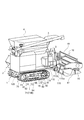
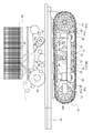
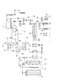
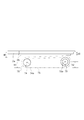
- the side view which shows the structure of the combine which concerns on one Embodiment of this invention The rear perspective view which similarly shows the structure of a combine.
- the side surface enlarged view which similarly shows the structure of the rear part of a driving
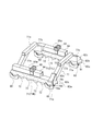
- the perspective view which similarly shows the structure of a drive case and a scraper.
- the rear view which similarly shows the structure of a drive case and a scraper.
- the top view which similarly shows the structure of a drive case and a scraper.
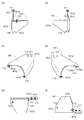
- (A) Front view similarly showing the configuration of the scraper (b) Same rear view (c) Same right side view (d) Same left side view (e) Same plan view (f) Same bottom view.
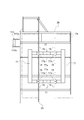
- the top view which similarly shows the structure of a body frame and a fuel tank.
- the bottom view which similarly shows the structure of a body frame.
- the work vehicle is not limited to the combine 100, and is a work vehicle including the traveling unit 1 and the body 2 provided on the upper part of the traveling unit 1.
- it may be a construction vehicle or the like.
- the combine 100 includes a traveling unit 1 and an airframe 2 provided on the upper part of the traveling unit 1.
- the traveling unit 1 includes a pair of left and right crawlers 70 and 70.
- a cockpit 3 is disposed on the front of the airframe 2.
- An engine 9 is mounted on the upper right rear of the machine body 2, a grain tank 4 is disposed in front of the engine 9, and a discharge auger 5 for discharging the grains from the grain tank 4 is provided at the rear of the machine body.
- the airframe 2 includes an upper frame 2a (see FIG. 5) formed in a rectangular frame shape in plan view, and a lower frame 2b (see FIG. 5) fixed on the lower surface of the upper frame 2a and having a longitudinal direction in the front-rear direction. have.
- a cutting part 10 is arranged in front of the machine body 2
- a threshing part 20 is arranged on the left side of the machine body 2
- a feeder house 30 communicates the rear end of the cutting part 10 and the front entrance of the threshing part 20.
- a side cover 7 is provided on the outer side surface of the threshing unit 20.
- a platform 12 is provided in the front part of the feeder house 30, and a lateral feed auger 13 is arranged in the left-right direction at a right angle to the traveling direction on the platform 12, and a cutting blade 14 is laterally installed in the lower front part of the lateral feed auger 13. Yes.
- Weeding plates 15 and 15 are provided at the left and right front ends of the platform 12, and a rear portion of a support arm 17 that supports a reel 16 is pivoted at the left and right ends of the rear portion of the platform 12.
- a power transmission mechanism 18 comprising a reel rotation driving belt, pulley, and the like.
- the reel 16 is moved up and down by a hydraulic cylinder (not shown) as an actuator interposed between the support arm 17 and the platform 12.
- a feeder conveyor 31 is provided as a transport unit so that the harvested cereal can be transported to the threshing unit 20.
- the threshing unit 20 is formed of a handling chamber 21 and a sorting unit 40.
- a handling cylinder 24 is arranged in the handling chamber 21. By rotation of the handling cylinder 24, the cereal straw is spirally conveyed to the rear of the handling chamber 21 and threshed.
- the handling cylinder 24 has a support shaft 24a (see FIG. 4) disposed in parallel with the longitudinal direction of the machine body, and rotates about the support shaft 24a as a fulcrum.
- a chopper (not shown) in which a plurality of cutting blades are planted on the rotating shaft is arranged below the rear part of the handling cylinder 24, and the waste transferred to the rear part of the handling chamber 21 by the handling cylinder 24 is finely arranged. After cutting, it is discharged outside the aircraft.
- the sorting unit 40 includes a swinging main body 42 having a receiving net (or concave) 22 disposed below the handling cylinder 24, and having a chaff sheave 41, a cereal plate, and the like.
- the first conveyor 46, the second conveyor 47, the second conveyor 47, etc. are arranged in order from the front side, and the grains, swarf, etc. leaking from the receiving net 22 are selected.
- the second item out of the leaked grain, sawdust, etc. is returned to the front part of the handling chamber 21 through the second conveyor 47 and the second reduction device 43.
- a travel speed change pump case 26 having a pair of swash plate variable left and right travel hydraulic pumps 25 is provided.
- the left / right traveling hydraulic pump 25 is connected to the engine 9 via a pulley or the like, and the power from the engine 9 is transmitted to the left / right traveling hydraulic pump 25.
- the left and right traveling hydraulic pump 25 is connected to traveling hydraulic motors 32 and 32 corresponding to the left and right crawlers 70 and 70, respectively.
- the traveling hydraulic motors 32 and 32 are connected to the drive wheels 73 via the power transmission mechanism 102.
- the power transmission mechanism 102 is stored in the drive case 105.
- the traveling hydraulic motors 32 and 32 are individually driven by the left and right traveling hydraulic pump 25, and the power of the left and right traveling hydraulic motors 32 and 32 is transmitted to the drive wheels 73 via the power transmission mechanism 102. Then, the left and right crawlers 70 and 70 are moved forward and backward by rotating forward and backward.
- the power from the engine 9 is transmitted to the handling cylinder 24 through the first counter shaft 33 and the second counter shaft 34, and further, through the support shaft 24 a of the handling cylinder 24, 46, the second conveyor 47, the second reduction device 43, and the swinging main body 42, respectively.
- the power from the engine 9 is transmitted to the feeder conveyor 31 through the support shaft 24a of the handling cylinder 24, and further, through the power transmission mechanism 18, the lateral feed auger 13, the cutting blade 14, and the cutting blade 10 Each is transmitted to the reel 16.
- the cutting operation is performed by weeding with the weed board 15, scraping the cereal with the rotation of the reel 16, cutting the stock side of the cereal with the cutting blade 14, and laterally feeding the harvested culm.
- the auger 13 is rotated to the center side, and is fed backward from the front end of the feeder house 30 by the feeder conveyor 31 to be supplied to the threshing unit 20.
- the cereal is threshed by the handling cylinder 24 in the threshing unit 20, and the grain leaked from the receiving net 22 is sorted by the sorting unit 40, and the first of them is stored in the Glen tank 4.
- each crawler 70 includes a track frame 71 arranged below the body 2, one on each of the left and right sides, a plurality of wheels 72 attached to the track frame 71, a track A drive wheel 73 provided behind the frame 71, a tension roller 74 provided in front of the track frame 71, a crawler belt 75 wound around the drive wheel 73 and the tension roller 74, and the tension roller 74 in the front-rear direction And a tension adjusting device 76 that is slid on.
- One track frame 71 is provided on each of the left and right sides, and the left and right track frames 71 will be described as 71L and 71R, respectively.
- the track frames 71L and 71R are provided on the lower surface of the airframe 2, and as shown in FIG. 10, the track frame 71L and the track frame 71R are configured in a bilaterally symmetric structure.
- a connecting frame 77 for connecting the track frame 71L and the track frame 71R is provided between the track frame 71L and the track frame 71R.
- Two connecting frames 77 are provided in the longitudinal direction of the fuselage, and an upper member 77a having a longitudinal direction in the left-right direction, and a lower member projecting from the left and right ends of the upper member 77a toward the outside of the fuselage and downward.
- 77b and 77b, and the tip ends of 77b are connected to the track frames 71L and 71R, respectively.
- the track frames 71L and 71R are connected to each other.
- a reinforcing member 78 is fixed to the lower surface of the lower member 77 b of the connecting frame 77.
- the reinforcing member 78 includes a triangular portion in side view and a portion protruding from the triangular portion in a direction parallel to the inclined surface of the lower member 77b, and the upper surface of the triangular portion is the lower frame 2b. It is fixed to the lower surface. Thereby, the connection frame 77 is fixed to the lower frame 2b.
- a plurality of rolling wheels 72 are arranged on the lower side of the track frames 71L and 71R.
- the wheel 72 is fixed to the track frames 71L and 71R so as to be rotatable.
- the crawler belt 75 is held in a grounded state.
- the drive wheel 73 provided behind the track frames 71L and 71R is composed of a sprocket that drives the crawler belt 75.
- the drive wheels 73 support the rear side of the crawler belt 75 and move the crawler belt 75 with the power transmitted from the power transmission mechanism 102.
- the height h1 of the center of the rotation shaft 74a of the tension roller 74 from the ground is lower than the height h2 of the center of the rotation shaft 73a of the drive wheel 73 from the ground. It is configured.
- the distance between the upper surface of each crawler 70, 70 and the lower surface of the fuselage is configured to increase toward the front. That is, as shown in FIG. 7, the distance d1 between the upper surface of the front end of the crawler 70 and the lower surface of the body 2 is formed to be larger than the distance d2 between the upper surface of the rear end of the crawler 70 and the lower surface of the body.
- each crawler 70 * 70 can also be arrange
- mud, waste, etc. that have adhered to the outer surface of the crawler belt 75 of the crawlers 70 and 70 and have moved upward are likely to fall in the lateral direction of the crawler belt 75.
- the amount of mud or waste that moves upward is reduced, running resistance is reduced, and cleaning becomes easier.
- the distance between the upper surface of each crawler 70 * 70 and the lower frame 2b lower surface is comprised so that it may become large as it goes ahead. That is, as shown in FIG.
- the distance d3 between the upper surface of the front end of the crawler 70 and the lower surface of the body 2 is formed to be larger than the distance d4 between the upper surface of the rear end of the crawler 70 and the lower surface of the body.
- the crawler belt 75 is configured by arranging a plurality of shoes 75a in an annular shape.
- the shoe 75a is made of iron and is fixed to the crawler chain 75b by screws.
- the shoe 75a includes a plate member 75c whose longitudinal direction is the left-right direction, and a plurality of convex members 75d provided on the upper and lower surfaces of the plate member 75c (the surface on the grounding surface and the crawler chain 75b side).
- the convex members 75d are provided in parallel with the longitudinal direction of the plate material 75c, and in this embodiment, three each are provided on one side.
- the shoe 75a Since the shoe 75a has convex members 75d on the upper and lower surfaces, even if the convex member 75d is worn due to the use of the shoes 75a, the upper and lower surfaces are switched and the upper surface (surface on the crawler chain 75b side). By arranging the convex member 75d suitable for the surface on the lower surface (grounding surface), a new convex member 75d can be used for the grounding surface. By configuring in this way, the life of the shoe 75a can be extended, and the running cost is reduced. Further, it is possible to save the trouble of preparing parts for replacing the shoe 75a.
- the tension roller 74 provided in front of the track frames 71L and 71R is a member that maintains the tension of the crawler belt 75.
- the tension roller 74 is fixed to the front end portion of the tension adjusting device 76 so as to be slidable in the front-rear direction.
- the tension adjusting device 76 is provided above the track frames 71 ⁇ / b> L and 71 ⁇ / b> R and is a support member 91 that supports the tension roller 74 and a sliding member connected to the rear end of the support member 91. 92, a biasing member 93 that biases the sliding member 92 forward, and a case 94 that houses the sliding member 92 and the biasing member 93, and the upper crawler belt 75 on the outer surface of the case 94. Is provided with a guide roller 95.
- the support member 91 is configured in a planar view type, and has a base portion 91 a whose longitudinal direction on the rear side is the left-right direction, and two protruding from the both ends of the base portion 91 a to the front side. It is comprised from the one support part 91b * 91b.
- a tension roller 74 is disposed in the middle in the left-right direction between the two support portions 91b and 91b.
- the rotation shaft 74a of the tension roller 74 protrudes from the center of the tension roller 74 in the left-right direction, and the tension roller 74 can be rotated by pivotally supporting the rotation shaft 74a with the support portions 91b and 91b on both sides. To support.
- the sliding member 92 is a quadrangular columnar member and is arranged so that the longitudinal direction is the front-rear direction.
- a rear surface of a base portion 91 a provided at the rear end of the support member 91 is fixed to the front end of the sliding member 92.
- the urging member 93 is disposed behind the sliding member 92 and urges the sliding member 92 forward.
- the urging member 93 is composed of a spring and can change the urging force by contracting in the front-rear direction.
- the rear portions of the urging member 93 and the sliding member 92 are stored in the case 94.
- the case 94 has a rectangular inner space with an open front, and the urging member 93 is always stored in the case 94. When the sliding member 92 slides backward, the rear part of the sliding member 92 is stored in the internal space of the case 94.
- the tension adjusting device 76 is arranged with the longitudinal direction as the front-rear direction, and its rear end is arranged near the center of the crawlers 70, 70 in the front-rear direction. More specifically, the rear end of the case 94 is disposed in the vicinity of the center in the front-rear direction of the crawlers 70 and 70 and behind the center in the front-rear direction.
- a guide roller 95 for supporting a crawler belt 75 on the outer surface of the case 94 and on the crawlers 70 and 70 is provided. As shown in FIG. 6, the guide roller 95 is provided at the center in the front-rear direction of the crawlers 70 and 70 and is rotatably supported by a stay member 95 a that is a support portion fixed to the case 94. . A non-grounding side (upper side) crawler belt 75 is held by the guide roller 95.
- the rear end surface 71a of the track frames 71L and 71R will be described with reference to FIGS.
- the rear end surface 71a of the track frame 71R will be described.
- the rear end surface 71a of the track frame 71R is cut out along the outer peripheral edge of the drive wheel 73, as shown in FIGS. More specifically, as shown in FIGS. 10 and 11, the rear end surface 71a of the track frame 71R is a first surface 79a that extends vertically upward from the intersection with the lower side in a side view, and a second surface that inclines backward as it goes downward. It is comprised from the surface 79b and the 3rd surface 79c extended perpendicularly upward from the upper end of the 2nd surface 79b.
- the inclination of the second surface 79b in the front-rear direction is formed along the outer peripheral edge of the drive wheel 73 as shown in FIG. With this configuration, the rear end surface 71 a of the track frame 71 is prevented from coming into contact with the drive wheels 73, and there is no gap between the track frame 71 and the drive wheels 73.
- a guide plate 81 is attached to the rear end surface 71a of the track frame 71.
- the guide plate 81 has a first surface 82a attached to the first surface 79a, a second surface 82b attached to the second surface 79b, and a third surface 82c attached to the third surface 79c.
- the inclination of the front-back direction of the 2nd surface 82b is formed along the outer periphery of the driving wheel 73 similarly to the 2nd surface 79b.
- the third surface 82c of the guide plate 81 is provided to extend further upward from the upper end of the third surface 79c. With this configuration, the front of the drive wheel 73 can be protected by the third surface 82 c of the guide plate 81. For example, even if the drive wheel 73 rotates while adhering mud and waste from the top to the front, the guide plate 81 can remove mud and waste and the like.
- a dropout prevention guide 83 for preventing the crawler belt 75 from dropping off is provided below the track frames 71L and 71R.
- two dropout prevention guides 83 are provided at the front end portion and the rear end portion of the track frames 71L and 71R.
- the slip-off prevention guide 83 is disposed on the left and right of the crawler belt 75, and prevents the crawler belt 75 from falling off by preventing the crawler belt 75 from shifting in the left-right direction.
- the rear end (P2 in FIG. 11) of the drop-off prevention guide 83 disposed on the rear side is a third surface 79c (P1 in FIG. 11) which is a portion protruding to the frontmost side of the rear end surface 71a of the track frame 71 in a side view. ) Is arranged behind.
- the rear end of the drop-off prevention guide 83 projects to the third surface 79c, which is the most projecting portion of the rear end surface 71a of the track frame 71, and to the rearmost side. It arrange
- the drop-off prevention guide 83 arranged at the rear part of the machine body 2 can be arranged as far back as possible.
- the scraper 101 that removes mud adhering to the crawler belt 75 and the drive wheel 73 is provided on the drive wheel 73 of each crawler 70.
- the scraper 101 is provided on the side of each drive wheel 73.
- the scraper 101 provided on the right drive wheel 73 will be described.
- the scraper 101 includes an attachment portion 101a attached to the lower frame 2b and a plate surface 101b protruding from the lower portion of the attachment portion 101a to the outside of the machine body.
- the attachment portion 101a is formed in a plate shape, and a screw hole 101c for inserting a screw 111 as a fixing member is provided in an upper portion thereof.
- the rear lower end of the mounting portion 101a is bent toward the inner side of the machine body (left side). Moreover, the screw hole 101c is provided in the rear upper part of the attachment part 101a, and the board surface 101b is provided in the front lower direction of the attachment part 101a.
- the plate surface 101 b is formed along the inner peripheral surface of the crawler belt 75. As shown in FIG. 15A, the plate surface 101 b is provided with two screw holes 101 d for inserting a screw 112 as a fixing member on the inner side (left side) of the machine body.
- the plate surface 101b is formed such that its rear end surface extends backward from the rear end on the drive wheel 73 side toward the rear end on the drive case 105 side. That is, as shown in FIG. 12, the rear end surface of the plate surface 101b is formed so as to incline rearward toward the inner side (left side) in the rear perspective view.
- the scraper 101 is fixed to a drive case 105 in which a power transmission mechanism 102 that transmits power to the machine body 2 and the drive wheels 73 is stored, and is disposed at a rear portion of the drive case 105. More specifically, the screw hole 101c of the attachment portion 101a and a hole (not shown) provided in the lower frame 2a are fixed by the screw 111. Further, a screw hole 101d in the plate surface 101b and a hole (not shown) provided in the drive case 105 are fixed by a screw 112.
- a fuel tank 110 is disposed on the upper surface of the airframe 2.
- the fuel tank 110 is disposed below the cockpit 3 and stores fuel to be supplied to the engine 9.
- a step member 115 is provided on the side surface of the airframe 2 at a position substantially the same as the fuel tank 110 and the front-rear direction of the airframe 2.
- the step member 115 is attached to the outer surface of the upper frame 2a of the machine body 2, and has a stay member 115a and a step plate 115b.
- the step plate 115b is supported at both ends by the lower end of the stay member 115a.
- the height of the step plate 115b is arranged to be lower than the height of the upper frame 2a and higher than the height of the upper surface of the crawler 70.
- the lower surface of the airframe 2 is formed to be a flat surface. That is, as shown in FIG. 4, the Kara 45, the first conveyor 46, and the second conveyor 47 are arranged above the upper frame 2 a of the machine body 2. Thereby, since the lowermost surface of the airframe 2 becomes the upper frame 2a, the distance between the airframe 2 and the ground can be increased.
- the combine includes the traveling unit 1 and the airframe 2 provided on the upper part of the traveling unit 1, and the traveling unit 1 includes a pair of left and right crawlers 70 and 70, and each crawler 70 is a track.
- a crawler belt 75 wound around the roller 74, and a scraper 101 for removing mud adhering to the crawler belt 75 and the drive wheel 73 is provided on the side of the drive wheel 73 of each crawler 70.
- 75 has a plate surface 101b formed along the inner circumferential surface.
- the scraper 101 is fixed to a drive case 105 in which a power transmission mechanism for transmitting power to the machine body 2 and the drive wheels 73 is stored, and is disposed at a rear portion of the drive case 105.
- a drive case 105 in which a power transmission mechanism for transmitting power to the machine body 2 and the drive wheels 73 is stored, and is disposed at a rear portion of the drive case 105.
- the scraper 101 is formed so as to extend backward from the rear end of the drive wheel 73 toward the rear end of the drive case 105. With this configuration, the adhering force of mud, waste, etc. can be removed while escaping to the outside, so that the scraper 101 is prevented from moving due to mud, waste, etc.
- the present invention is applicable to a work vehicle that includes a traveling unit and an airframe provided on the upper part of the traveling unit, and the traveling unit includes a pair of left and right crawlers.
Landscapes
- Engineering & Computer Science (AREA)
- Chemical & Material Sciences (AREA)
- Combustion & Propulsion (AREA)
- Transportation (AREA)
- Mechanical Engineering (AREA)
- Harvester Elements (AREA)
Abstract
履帯後端部において、泥や排藁等の付着を除去することができる作業車両を提供する。走行部1と、走行部1の上部に設けられた機体2と、を備えるコンバインであって、走行部1は、左右一対のクローラ70・70を備え、各クローラ70はトラックフレーム71と、トラックフレーム71に複数取り付けられた転輪72と、トラックフレーム71の後方に設けられた駆動輪73と、トラックフレーム71の前方に設けられたテンションローラ74と、駆動輪73とテンションローラ74とに巻回される履帯75と、を有し、各クローラ70の駆動輪73の上方に、履帯75及び駆動輪73に付着した泥を取り除くスクレーパー101を設け、スクレーパー101は、履帯75の内周面に沿って形成された板面101bを有する。
Description
本発明は、作業車両の技術に関し、特に、走行部と、前記走行部の上部に設けられた機体と、を備える作業車両であって、走行部は、左右一対のクローラを備える作業車両の技術に関する。
従来、走行部と、前記走行部の上部に設けられた機体と、を備える作業車両であって、走行部は、左右一対のクローラを備える作業車両が公知となっている(例えば、特許文献1参照)。
従来技術に係る作業車両のクローラは、トラックフレームと、前記トラックフレームに複数取り付けられた転輪と、前記走行フレームの後方に設けられた駆動輪と、前記トラックフレームの前方に設けられたテンションローラと、前記駆動輪とテンションローラとに巻回される履帯と、を有する。
従来技術に係る作業車両のクローラは、トラックフレームと、前記トラックフレームに複数取り付けられた転輪と、前記走行フレームの後方に設けられた駆動輪と、前記トラックフレームの前方に設けられたテンションローラと、前記駆動輪とテンションローラとに巻回される履帯と、を有する。
従来技術においては、作業車両が前進する際に泥や排藁等が履帯と共に持ち上がってくるのは、履帯後端部であり、後端部において、泥や排藁等の付着を除去しておく必要があった。
そこで、本発明は係る課題に鑑み、履帯後端部において、泥や排藁等の付着を除去することができる作業車両を提供する。
本発明の解決しようとする課題は以上の如くであり、次にこの課題を解決するための手段を説明する。
即ち、本発明においては、走行部と、前記走行部の上部に設けられた機体と、を備える作業車両であって、前記走行部は、左右一対のクローラを備え、前記各クローラはトラックフレームと、前記トラックフレームに複数取り付けられた転輪と、前記トラックフレームの後方に設けられた駆動輪と、前記トラックフレームの前方に設けられたテンションローラと、前記駆動輪とテンションローラとに巻回される履帯と、を有し、前記各クローラの駆動輪の側方に、履帯及び駆動輪に付着した泥を取り除くスクレーパーを設け、前記スクレーパーは、履帯の内周面に沿って形成された板面を有するものである。
本発明においては、前記スクレーパーは、機体及び駆動輪へ動力を伝達する動力伝達機構が格納された駆動ケースに固設され、前記駆動ケースの後部に配置されたものである。
本発明においては、前記スクレーパーは、前記駆動輪側の後端から駆動ケース側の後端に向かうにつれて後方へ延伸するように形成されたものである。
本発明の効果として、以下に示すような効果を奏する。
本発明においては、履帯後端部において、スクレーパーによってクローラ内部に付着した泥や排藁等を除去することができる。
本発明においては、履帯後端部において、スクレーパーによってクローラ内部に付着した泥や排藁等を除去することができる。スクレーパーを機体及び駆動ケースに固定することにより、泥や排藁等によって、スクレーパーが移動するのを防止する。また、駆動ケースの後部にスクレーパーを配置することにより駆動ケース後方のスペースを有効に活用することができる。
本発明においては、泥や排藁等の付着する力を外側へ逃がしつつ除去できるので、泥や排藁等によって、スクレーパーが移動するのを防止する。
次に、発明の実施の形態を説明する。
まず、図1から図3を用いて、本実施形態にかかる作業車両の一例であるコンバイン100の全体構成を説明する。なお、本実施形態においては、コンバイン100について説明するが、作業車両はコンバイン100に限定するものではなく、走行部1と、走行部1の上部に設けられた機体2と、を備える作業車両であれば、例えば、建設車両等であってもよい。
図1及び図2に示すように、コンバイン100は、走行部1と、走行部1の上部に設けられた機体2と、を備える。また、走行部1は、左右一対のクローラ70・70を備える。
機体2の前部上には操縦席3を配設している。機体2の右後上にはエンジン9を載置し、その前方にグレンタンク4を配置し、このグレンタンク4より穀粒を排出するための排出オーガ5が機体後方に設けられている。
機体2は平面視四角形の枠状に形成された上部フレーム2a(図5参照)と、上部フレーム2aの下面に固設された、長手方向を前後方向とする下部フレーム2b(図5参照)とを有している。
機体2の前部上には操縦席3を配設している。機体2の右後上にはエンジン9を載置し、その前方にグレンタンク4を配置し、このグレンタンク4より穀粒を排出するための排出オーガ5が機体後方に設けられている。
機体2は平面視四角形の枠状に形成された上部フレーム2a(図5参照)と、上部フレーム2aの下面に固設された、長手方向を前後方向とする下部フレーム2b(図5参照)とを有している。
また、機体2の前方には刈取部10が配置され、機体2左側上に脱穀部20が配設され、刈取部10の後端と脱穀部20の前部入口をフィーダハウス30によって連通している。脱穀部20の機体外側側面には、サイドカバー7が設けられている。
フィーダハウス30の前部にプラットホーム12を設けており、プラットホーム12には進行方向と直角に横送りオーガ13が左右方向に配置され、横送りオーガ13の前下部に刈刃14が横設されている。
プラットホーム12の左右両側の前端に分草板15・15を設け、プラットホーム12の後部の左右両端にはリール16を横架した支持アーム17の後部が枢支され、この支持アーム17の左右一側にはリール回転駆動用のベルトやプーリ等からなる動力伝達機構18が設けられている。このリール16は、支持アーム17とプラットホーム12との間に介装されたアクチュエータとしての図示せぬ油圧シリンダによって昇降される。
プラットホーム12の左右両側の前端に分草板15・15を設け、プラットホーム12の後部の左右両端にはリール16を横架した支持アーム17の後部が枢支され、この支持アーム17の左右一側にはリール回転駆動用のベルトやプーリ等からなる動力伝達機構18が設けられている。このリール16は、支持アーム17とプラットホーム12との間に介装されたアクチュエータとしての図示せぬ油圧シリンダによって昇降される。
フィーダハウス30内には搬送部としてフィーダコンベア31を設け、刈り取った穀稈を脱穀部20へ搬送するようにしている。
図1及び図3に示すように、脱穀部20は、扱室21及び選別部40から形成される。
扱室21内には、図1に示すように、扱胴24が配され、この扱胴24の回転により、穀稈は、螺旋状に扱室21後方へ搬送され、脱穀される。扱胴24は、支軸24a(図4参照)が機体前後方向と平行に配置され、支軸24aを支点として回転する。
扱室21内には、図1に示すように、扱胴24が配され、この扱胴24の回転により、穀稈は、螺旋状に扱室21後方へ搬送され、脱穀される。扱胴24は、支軸24a(図4参照)が機体前後方向と平行に配置され、支軸24aを支点として回転する。
さらに、扱胴24の後部下方には、回転軸に複数の切断刃を植設してなるチョッパー(図示せず)を配し、扱胴24により扱室21後部へ移送される排稈を細かく切断した後に、機体外部へ排出するようにしている。
また、図3に示すように、選別部40は、扱胴24の下方に受網(またはコンケーブ)22が配され、チャフシーブ41や流穀板等を有する揺動本体42や、揺動本体42の下方で前側から順に配される唐箕45、一番コンベア46、二番コンベア47等からなり、受網22から漏下する穀粒や藁屑等の選別を行うようにしている。前記漏下する穀粒や藁屑等のうち二番物は、二番コンベア47、二番還元装置43を経て、扱室21の前部に還元するようにしている。
次に、図4を用いてコンバイン100の駆動構造を説明する。
図4に示すように、一対の斜板可変型の左右走行油圧ポンプ25を有する走行変速用のポンプケース26を備える。左右走行油圧ポンプ25は、エンジン9とプーリ等を介して連結されており、エンジン9からの動力が左右走行油圧ポンプ25へと伝達される。左右走行油圧ポンプ25は、左右のクローラ70・70に対応する走行油圧モータ32・32と連結している。走行油圧モータ32・32は動力伝達機構102を介して駆動輪73と連結している。動力伝達機構102は駆動ケース105に格納されている。このように構成することにより、左右走行油圧ポンプ25によって走行油圧モータ32・32を個別に駆動し、左右走行油圧モータ32・32の動力を動力伝達機構102を介して駆動輪73に伝達することで、左右クローラ70・70を正逆転させて前後進移動させる。
図4に示すように、一対の斜板可変型の左右走行油圧ポンプ25を有する走行変速用のポンプケース26を備える。左右走行油圧ポンプ25は、エンジン9とプーリ等を介して連結されており、エンジン9からの動力が左右走行油圧ポンプ25へと伝達される。左右走行油圧ポンプ25は、左右のクローラ70・70に対応する走行油圧モータ32・32と連結している。走行油圧モータ32・32は動力伝達機構102を介して駆動輪73と連結している。動力伝達機構102は駆動ケース105に格納されている。このように構成することにより、左右走行油圧ポンプ25によって走行油圧モータ32・32を個別に駆動し、左右走行油圧モータ32・32の動力を動力伝達機構102を介して駆動輪73に伝達することで、左右クローラ70・70を正逆転させて前後進移動させる。
また、エンジン9からの動力は、第一カウンタ軸33、第二カウンタ軸34を介して扱胴24へと伝達され、さらに、扱胴24の支軸24aを介して、唐箕45、一番コンベア46、二番コンベア47、二番還元装置43、及び揺動本体42へとそれぞれ伝達される。
また、エンジン9からの動力は、扱胴24の支軸24aを介してフィーダコンベア31へ伝達され、さらに、動力伝達機構18を介して、刈取部10の横送りオーガ13、刈刃14、及びリール16へとそれぞれ伝達される。
また、エンジン9からの動力は、扱胴24の支軸24aを介してフィーダコンベア31へ伝達され、さらに、動力伝達機構18を介して、刈取部10の横送りオーガ13、刈刃14、及びリール16へとそれぞれ伝達される。
以上の構成により、刈取作業は、分草板15によって分草し、リール16の回転によって穀稈を掻き込み、刈刃14によって穀稈の株元側を刈取り、刈り取られた穀稈を横送りオーガ13の回転によって中央側へ横送りし、中央のフィーダハウス30前端からフィーダコンベア31によって後方へ搬送して脱穀部20へ供給する。
そして、穀稈は、脱穀部20内の扱胴24によって脱穀され、受網22より漏下した穀粒等は選別部40によって選別され、そのうちの一番物は前記グレンタンク4内に貯溜され、また、二番物は、二番還元装置43を経た後に脱穀部20の前端部に投入され、再選別にかけられる。また、脱穀された残りの排稈は、チョッパーにより細かく切断された後、機体外部へ排出される。
そして、穀稈は、脱穀部20内の扱胴24によって脱穀され、受網22より漏下した穀粒等は選別部40によって選別され、そのうちの一番物は前記グレンタンク4内に貯溜され、また、二番物は、二番還元装置43を経た後に脱穀部20の前端部に投入され、再選別にかけられる。また、脱穀された残りの排稈は、チョッパーにより細かく切断された後、機体外部へ排出される。
次に、走行部1のクローラ70・70について図3並びに図5から図14を用いて説明する。
各クローラ70は、図5及び図6に示すように、機体2の下方であって、左右に一つずつ配置されたトラックフレーム71と、トラックフレーム71に複数取り付けられた転輪72と、トラックフレーム71の後方に設けられた駆動輪73と、トラックフレーム71の前方に設けられたテンションローラ74と、駆動輪73とテンションローラ74とに巻回される履帯75と、テンションローラ74を前後方向に摺動させるテンション調整装置76と、を有する。
各クローラ70は、図5及び図6に示すように、機体2の下方であって、左右に一つずつ配置されたトラックフレーム71と、トラックフレーム71に複数取り付けられた転輪72と、トラックフレーム71の後方に設けられた駆動輪73と、トラックフレーム71の前方に設けられたテンションローラ74と、駆動輪73とテンションローラ74とに巻回される履帯75と、テンションローラ74を前後方向に摺動させるテンション調整装置76と、を有する。
トラックフレーム71は、左右に一つずつ設けられており、以下左右のトラックフレーム71をそれぞれ71L・71Rとして説明する。トラックフレーム71L・71Rは機体2の下面に設けられており、図10に示すように、トラックフレーム71Lとトラックフレーム71Rとは左右対称の構造によって構成されている。トラックフレーム71Lとトラックフレーム71Rとの間には、トラックフレーム71Lとトラックフレーム71Rとを連結するための連結フレーム77が設けられている。
連結フレーム77は、機体前後方向に二つ設けられており、左右方向を長手方向とする上部部材77aと、上部部材77aの左右両端部から機体外方向および下方向に向けて突設した下部部材77b・77bとを有しており、77bの先端部がトラックフレーム71L・71Rにそれぞれ連結されている。これにより、トラックフレーム71L・71Rはたがいに連結される。また連結フレーム77の下側部材77bの下面には、補強部材78が固設されている。補強部材78は、側面視三角形状の部分と三角形状の部分から下部部材77bの傾斜面と平行な方向に突設した部分とから構成されており、三角形状の部分の上面が下部フレーム2bの下面と固定されている。これにより、連結フレーム77は、下部フレーム2bに固設される。
転輪72は、トラックフレーム71L・71Rの下辺に複数個配置されている。転輪72はトラックフレーム71L・71Rに回動可能に固設されており、転輪72が履帯75の接地側内面から履帯75と接触することにより、履帯75を接地状態に保持する。
トラックフレーム71L・71Rの後方に設けられた駆動輪73は、図3に示すように、履帯75を駆動するスプロケットで構成されている。駆動輪73は、履帯75の後側を支持するとともに、動力伝達機構102から伝達された動力により履帯75を移動させる。
また、図7に示すように、テンションローラ74の回動軸74aの中心の地面からの高さh1は、駆動輪73の回動軸73aの中心の地面からの高さh2よりも低くなるように構成されている。このように構成することにより、各クローラ70・70の上面と機体下面との間の距離は、前方に向かうにつれて大きくなるように構成したものである。すなわち、図7に示すように、クローラ70前端上面と機体2下面との距離d1の方が、クローラ70後端上面と機体下面との距離d2よりも大きくなるように形成している。
また、図8に示すように、各クローラ70・70の上面を、下部フレーム2bの下面よりも下方に配置することもできる。このように構成することにより、各クローラ70・70の履帯75の接地側外面に付着して上方へ移動してきた泥や排藁等が履帯75の側面方向へ落ちやすくなる。これにより、上方へ移動する泥や排藁等の量を減少させ、走行抵抗が軽減し、掃除がし易くなる。
また、各クローラ70・70の上面と下部フレーム2b下面との間の距離は、前方に向かうにつれて大きくなるように構成したものである。すなわち、図8に示すように、クローラ70前端上面と機体2下面との距離d3の方が、クローラ70後端上面と機体下面との距離d4よりも大きくなるように形成している。このように構成することにより、各クローラ70・70の履帯75の接地側外面に付着して上方へ移動してきた泥や排藁等が下部フレーム2bに引っ掛かり停滞することがなくなる。これにより、クローラ70の上面をスムーズに前まで移動させることができる。
また、各クローラ70・70の上面と下部フレーム2b下面との間の距離は、前方に向かうにつれて大きくなるように構成したものである。すなわち、図8に示すように、クローラ70前端上面と機体2下面との距離d3の方が、クローラ70後端上面と機体下面との距離d4よりも大きくなるように形成している。このように構成することにより、各クローラ70・70の履帯75の接地側外面に付着して上方へ移動してきた泥や排藁等が下部フレーム2bに引っ掛かり停滞することがなくなる。これにより、クローラ70の上面をスムーズに前まで移動させることができる。
図9に示すように、履帯75は、複数のシュー75aを環状に並べて構成されている。シュー75aは、鉄で構成されており、クローラチェーン75bに螺子によって固定されている。また、シュー75aは、左右方向を長手方向とする板材75cと、板材75cの上下面(接地面及びクローラチェーン75b側の面)に複数個設けられた凸部材75dと、を有している。凸部材75dは板材75cの長手方向と平行に設けられており、本実施形態においては、片面に各3個ずつ設けられている。
シュー75aは、上下面に凸部材75dを有しているので、シュー75aを使用することにより凸部材75dが摩耗した場合であっても、上下面を入れ替えて上面(クローラチェーン75b側の面)にあった凸部材75dを下面(接地面)に配置することにより、新しい凸部材75dを接地面に使用することができる。
このように構成することにより、シュー75aの長寿命化を図ることができ、ランニングコストが下がる。また、シュー75aを交換するための部品を用意する手間が省ける。
このように構成することにより、シュー75aの長寿命化を図ることができ、ランニングコストが下がる。また、シュー75aを交換するための部品を用意する手間が省ける。
トラックフレーム71L・71Rの前方に設けられたテンションローラ74は、履帯75のテンションを維持する部材である。テンションローラ74は、テンション調整装置76の前端部に前後方向摺動可能に固定されている。
テンション調整装置76は、図5及び図6に示すように、トラックフレーム71L・71Rの上方に設け、テンションローラ74を軸支する支持部材91と支持部材91の後端に連結された摺動部材92と、摺動部材92を前方向へ付勢する付勢部材93と、摺動部材92及び付勢部材93を収納するケース94と、を有し、ケース94の外側面に上側の履帯75を支持するためのガイド転輪95が設けられたものである。
支持部材91は、図3及び図6に示すように、平面視門型に構成されており、後側の長手方向を左右方向とする基部91aと、基部91aの両端から前側へ突設した二つの支持部91b・91bとから構成されている。二つの支持部91b・91bの左右方向中間にテンションローラ74が配置されている。テンションローラ74の回動軸74aはテンションローラ74の中心から左右方向へ突設しており、回動軸74aを両側の支持部91b・91bで軸支することにより、テンションローラ74を回動可能に支持する。
摺動部材92は、四角柱状の部材であり長手方向が前後方向となるように配置している。摺動部材92の前端には、支持部材91の後端に設けられた基部91aの後面が固設されている。このように構成することにより、摺動部材92の前後方向への摺動に合わせて、支持部材91及びテンションローラ74が前後方向へ摺動する。
付勢部材93は、摺動部材92の後方に配置され、摺動部材92を前方へ付勢している。付勢部材93は、バネで構成されており、前後方向に収縮することにより付勢力を変化させることができる。付勢部材93及び摺動部材92の後部は、ケース94に格納されている。ケース94は、前部が開口した四角形状の内部空間を有しており、付勢部材93は常にケース94内に格納されている。摺動部材92が後方へ摺動した場合には、摺動部材92の後部がケース94の内部空間へ格納される。
テンション調整装置76は長手方向を前後方向として配置し、その後端が、クローラ70・70の前後方向中央近傍に配置される。より詳しくは、ケース94の後端が、クローラ70・70の前後方向中央近傍であって、前後方向中央よりも後方に配置される。
また、ケース94の外側面であって、クローラ70・70上側の履帯75を支持するためのガイド転輪95が設けられる。ガイド転輪95は、図6に示すように、クローラ70・70の前後方向中央に設けられており、ケース94に固設された支持部であるステー部材95aによって回動可能に支持されている。ガイド転輪95によって非接地側(上側)の履帯75が保持されている。
次に、トラックフレーム71L・71Rの後端面71aについて図6、図10及び図11を用いて説明する。ここではトラックフレーム71Rの後端面71aについて説明する。
トラックフレーム71Rの後端面71aは、図6、図10及び図11に示すように、駆動輪73の外周縁部に沿って切り欠かれている。より詳細には、図10及び図11に示すように、トラックフレーム71Rの後端面71aは側面視下辺との交点から垂直上方に延びる第一面79aと、下方に向かうにつれて後方に傾斜する第二面79bと、第二面79bの上端から垂直上方に延びる第三面79cとから構成される。
トラックフレーム71Rの後端面71aは、図6、図10及び図11に示すように、駆動輪73の外周縁部に沿って切り欠かれている。より詳細には、図10及び図11に示すように、トラックフレーム71Rの後端面71aは側面視下辺との交点から垂直上方に延びる第一面79aと、下方に向かうにつれて後方に傾斜する第二面79bと、第二面79bの上端から垂直上方に延びる第三面79cとから構成される。
第二面79bの前後方向の傾きは、図10に示すように、駆動輪73の外周縁に沿うように形成されている。このように構成することにより、トラックフレーム71の後端面71aが駆動輪73に接触することを防止しつつ、トラックフレーム71と駆動輪73との間に隙間がなくなるように構成している。
また、トラックフレーム71の後端面71aに、ガイド板81が貼設されている。ガイド板81は、第一面79aに貼設された第一面82aと、第二面79bに貼設された第二面82bと、第三面79cに貼設された第三面82cを有し、第二面82bの前後方向の傾きは、第二面79bと同様に、駆動輪73の外周縁に沿うように形成されている。
ガイド板81の第三面82cは、第三面79cの上端から更に上方へと延伸して設けられている。このように構成することにより、駆動輪73の前方をガイド板81の第三面82cによって保護することが可能となる。例えば、駆動輪73が、上方から前方へと泥や排藁等を付着させながら回転した場合であっても、ガイド板81によって泥や排藁等を除去することができる。
トラックフレーム71L・71Rの下方には履帯75の脱落を防止する脱落防止ガイド83を設けている。脱落防止ガイド83は、本実施形態においては、トラックフレーム71L・71Rの前端部と後端部とに二つ設けられている。脱落防止ガイド83は、履帯75の左右に配置されており、履帯75の左右方向のずれを防止して履帯75の脱落を防止する。
後側に配置された脱落防止ガイド83の後端(図11におけるP2)は、側面視において、トラックフレーム71の後端面71aの最も前側へ張り出した部分である第三面79c(図11におけるP1)よりも後方に配置されている。詳細には、脱落防止ガイド83の後端は、側面視において、図11に示すように、トラックフレーム71の後端面71aの最も前側へ張り出した部分である第三面79cと最も後側へ張り出した部分である第一面79a(図11におけるP3)との間に位置するように配置されている。このように構成することにより、機体2後部に配置した脱落防止ガイド83を可能な限り後方へ配置することができる。
また、各クローラ70の駆動輪73に、履帯75及び駆動輪73に付着した泥を取り除くスクレーパー101を設けている。スクレーパー101は、各駆動輪73の側方に設けられている。ここでは、右側の駆動輪73に設けられたスクレーパー101について説明する。
スクレーパー101は、図15(a)から(f)に示すように、下部フレーム2bに取り付ける取付部101aと、取付部101aの下部から機体外側へ突出した板面101bとから構成されている。
取付部101aは、板状に構成されており、その上部に固定部材としての螺子111を挿入するための螺子孔101cが設けられている。取付部101aは後下端が、機体内側方向(左側)へと屈曲している。また螺子孔101cは取付部101aの後上部に設けられており、取付部101aの前下方に板面101bが設けられている。
スクレーパー101は、図15(a)から(f)に示すように、下部フレーム2bに取り付ける取付部101aと、取付部101aの下部から機体外側へ突出した板面101bとから構成されている。
取付部101aは、板状に構成されており、その上部に固定部材としての螺子111を挿入するための螺子孔101cが設けられている。取付部101aは後下端が、機体内側方向(左側)へと屈曲している。また螺子孔101cは取付部101aの後上部に設けられており、取付部101aの前下方に板面101bが設けられている。
板面101bは、履帯75の内周面に沿って形成される。板面101bは、図15(a)に示すように、その機体内側(左側)に固定部材としての螺子112を挿入するための螺子孔101dが二つ設けられている。
板面101bは、その後端面が駆動輪73側の後端から駆動ケース105側の後端に向かうにつれて後方へ延伸するように形成される。すなわち、図12に示すように、板面101bの後端面は、後方斜視において、機体内側(左側)に向かうにしたがって、後方へ傾斜するように形成されている。このように構成することにより、履帯75内部において後端面と接触して削られた泥や排藁が機体内側方向へと移動して地面へ落下しやすくなり、履帯75内部での泥や排藁の詰まりを防止することができる。
板面101bは、その後端面が駆動輪73側の後端から駆動ケース105側の後端に向かうにつれて後方へ延伸するように形成される。すなわち、図12に示すように、板面101bの後端面は、後方斜視において、機体内側(左側)に向かうにしたがって、後方へ傾斜するように形成されている。このように構成することにより、履帯75内部において後端面と接触して削られた泥や排藁が機体内側方向へと移動して地面へ落下しやすくなり、履帯75内部での泥や排藁の詰まりを防止することができる。
次に、図11から図14において、スクレーパー101の駆動ケース105への取付について説明する。
スクレーパー101は、機体2及び駆動輪73へ動力を伝達する動力伝達機構102が格納された駆動ケース105に固設され、駆動ケース105の後部に配置される。より詳細には、取付部101aの螺子孔101cと、下部フレーム2aに設けられた図示せぬ孔とを螺子111によって固定している。また、板面101bの螺子孔101dと、駆動ケース105に設けられた図示せぬ孔とを螺子112によって固定している。
スクレーパー101は、機体2及び駆動輪73へ動力を伝達する動力伝達機構102が格納された駆動ケース105に固設され、駆動ケース105の後部に配置される。より詳細には、取付部101aの螺子孔101cと、下部フレーム2aに設けられた図示せぬ孔とを螺子111によって固定している。また、板面101bの螺子孔101dと、駆動ケース105に設けられた図示せぬ孔とを螺子112によって固定している。
また、図2及び図16に示すように、機体2の上面に燃料タンク110が配置されている。燃料タンク110は、操縦席3の下方に配置されており、エンジン9に供給するための燃料を貯蔵する。
図2、図16及び図17に示すように、機体2側面であって、燃料タンク110と機体2前後方向略同一の位置にステップ部材115が設けられる。ステップ部材115は機体2の上部フレーム2aの外側面に取り付けられており、ステー部材115aとステップ板115bとを有する。ステップ板115bはステー部材115aの下端によって両端部を支持されている。ステップ板115bの高さは、上部フレーム2aの高さよりも低く、クローラ70上面の高さよりも高い位置となるように配置されている。このように構成することにより、上部フレーム2aの上面に配置された燃料タンク110に燃料を供給する際に、作業者が、ステップ部材115に足をかけることで燃料タンク110への供給をし易くすることができる。
また、図5、図16及び図17に示すように、機体2の下面が平面となるように形成している。すなわち、図4に示すように、唐箕45、一番コンベア46、二番コンベア47が機体2の上部フレーム2aよりも上側になるように配置している。これにより、機体2の最下面が上部フレーム2aとなるため、機体2と地面との距離を開けることができる。
以上のように、走行部1と、走行部1の上部に設けられた機体2と、を備えるコンバインであって、走行部1は、左右一対のクローラ70・70を備え、各クローラ70はトラックフレーム71と、トラックフレーム71に複数取り付けられた転輪72と、トラックフレーム71の後方に設けられた駆動輪73と、トラックフレーム71の前方に設けられたテンションローラ74と、駆動輪73とテンションローラ74とに巻回される履帯75と、を有し、各クローラ70の駆動輪73の側方に、履帯75及び駆動輪73に付着した泥を取り除くスクレーパー101を設け、スクレーパー101は、履帯75の内周面に沿って形成された板面101bを有するものである。
このように構成することにより、履帯75後端部において、スクレーパー101によってクローラ70内部に付着した泥や排藁等を除去することができる。
このように構成することにより、履帯75後端部において、スクレーパー101によってクローラ70内部に付着した泥や排藁等を除去することができる。
また、スクレーパー101は、機体2及び駆動輪73へ動力を伝達する動力伝達機構が格納された駆動ケース105に固設され、前記駆動ケース105の後部に配置されたものである。
このように構成することにより、履帯75後端部において、スクレーパー101によってクローラ70内部に付着した泥や排藁等を除去することができる。スクレーパー101を機体2及び駆動ケース105に固定することにより、泥や排藁等によって、スクレーパー101が移動するのを防止する。また、駆動ケース105の後部にスクレーパー101を配置することにより駆動ケース105後方のスペースを有効に活用することができる。
このように構成することにより、履帯75後端部において、スクレーパー101によってクローラ70内部に付着した泥や排藁等を除去することができる。スクレーパー101を機体2及び駆動ケース105に固定することにより、泥や排藁等によって、スクレーパー101が移動するのを防止する。また、駆動ケース105の後部にスクレーパー101を配置することにより駆動ケース105後方のスペースを有効に活用することができる。
また、スクレーパー101は、駆動輪73側の後端から駆動ケース105側の後端に向かうにつれて後方へ延伸するように形成されたものである。
このように構成することにより、泥や排藁等の付着する力を外側へ逃がしつつ除去できるので、泥や排藁等によって、スクレーパー101が移動するのを防止する。
このように構成することにより、泥や排藁等の付着する力を外側へ逃がしつつ除去できるので、泥や排藁等によって、スクレーパー101が移動するのを防止する。
本発明は、走行部と、前記走行部の上部に設けられた機体と、を備え、走行部が左右一対のクローラを備える作業車両に利用可能である。
100 コンバイン(作業車両)
1 走行部
2 機体
2a 下部フレーム
3 操縦席
4 グレンタンク
5 排出オーガ
7 サイドカバー
10 刈取部
20 脱穀部
70 クローラ
71 トラックフレーム
72 転輪
73 駆動輪
74 テンションローラ
75 履帯
76 テンション調整装置
91 支持部材
92 摺動部材
93 付勢部材
94 ケース
95 ガイド転輪
101 スクレーパー
105 駆動ケース
1 走行部
2 機体
2a 下部フレーム
3 操縦席
4 グレンタンク
5 排出オーガ
7 サイドカバー
10 刈取部
20 脱穀部
70 クローラ
71 トラックフレーム
72 転輪
73 駆動輪
74 テンションローラ
75 履帯
76 テンション調整装置
91 支持部材
92 摺動部材
93 付勢部材
94 ケース
95 ガイド転輪
101 スクレーパー
105 駆動ケース
Claims (3)
- 走行部と、前記走行部の上部に設けられた機体と、を備える作業車両であって、
前記走行部は、左右一対のクローラを備え、
前記各クローラはトラックフレームと、前記トラックフレームに複数取り付けられた転輪と、前記トラックフレームの後方に設けられた駆動輪と、前記トラックフレームの前方に設けられたテンションローラと、前記駆動輪とテンションローラとに巻回される履帯と、を有し、
前記各クローラの駆動輪の側方に、履帯及び駆動輪に付着した泥を取り除くスクレーパーを設け、
前記スクレーパーは、履帯の内周面に沿って形成された板面を有することを特徴とする作業車両。 - 前記スクレーパーは、機体及び駆動輪へ動力を伝達する動力伝達機構が格納された駆動ケースに固設され、前記駆動ケースの後部に配置されたことを特徴とする請求項1に記載の作業車両。
- 前記スクレーパーは、前記駆動輪側の後端から駆動ケース側の後端に向かうにつれて後方へ延伸するように形成されたことを特徴とする請求項2に記載の作業車両。
Priority Applications (1)
| Application Number | Priority Date | Filing Date | Title |
|---|---|---|---|
| CN201480053890.0A CN105593111A (zh) | 2013-09-30 | 2014-09-29 | 作业车辆 |
Applications Claiming Priority (2)
| Application Number | Priority Date | Filing Date | Title |
|---|---|---|---|
| JP2013-204692 | 2013-09-30 | ||
| JP2013204692A JP2015067208A (ja) | 2013-09-30 | 2013-09-30 | 作業車両 |
Publications (1)
| Publication Number | Publication Date |
|---|---|
| WO2015046533A1 true WO2015046533A1 (ja) | 2015-04-02 |
Family
ID=52743654
Family Applications (1)
| Application Number | Title | Priority Date | Filing Date |
|---|---|---|---|
| PCT/JP2014/075953 Ceased WO2015046533A1 (ja) | 2013-09-30 | 2014-09-29 | 作業車両 |
Country Status (3)
| Country | Link |
|---|---|
| JP (1) | JP2015067208A (ja) |
| CN (1) | CN105593111A (ja) |
| WO (1) | WO2015046533A1 (ja) |
Cited By (3)
| Publication number | Priority date | Publication date | Assignee | Title |
|---|---|---|---|---|
| US20180072359A1 (en) * | 2016-09-09 | 2018-03-15 | Prinoth S.P.A. | Snow grooming vehicle |
| WO2020013751A1 (en) * | 2018-07-09 | 2020-01-16 | BAE Systems Hägglunds Aktiebolag | Deflector arrangement for a tracked vehicle |
| KR102912528B1 (ko) * | 2024-09-30 | 2026-01-14 | 주식회사 현대에버다임 | 무한궤도형 주행장치의 퇴적물 제거 시스템 |
Families Citing this family (5)
| Publication number | Priority date | Publication date | Assignee | Title |
|---|---|---|---|---|
| CN106005072A (zh) * | 2016-07-30 | 2016-10-12 | 浙江元创橡胶履带有限公司 | 带刮泥结构的车辆用橡胶履带 |
| CN106828637B (zh) * | 2017-02-09 | 2019-08-23 | 绍兴市亿跃智能科技有限公司 | 一种带轨迹块的防缠绕履带驱动轮 |
| CN106697092B (zh) * | 2017-02-10 | 2019-02-19 | 桐乡市瑞远纺织有限公司 | 一种带齿轮的防缠绕履带驱动轮 |
| CN107458487A (zh) * | 2017-08-09 | 2017-12-12 | 宿州云宏建设安装有限公司 | 一种挖掘机履带泥土清理装置 |
| JP7524757B2 (ja) | 2020-07-30 | 2024-07-30 | コベルコ建機株式会社 | クローラ式車両のクローラユニット |
Citations (3)
| Publication number | Priority date | Publication date | Assignee | Title |
|---|---|---|---|---|
| JPS59106779U (ja) * | 1983-01-06 | 1984-07-18 | セイレイ工業株式会社 | 雪上車のクロ−ラ走行部における排雪装置 |
| JP2002308160A (ja) * | 2001-04-10 | 2002-10-23 | Hitachi Constr Mach Co Ltd | 装軌車両の泥落し装置 |
| JP2004217154A (ja) * | 2003-01-17 | 2004-08-05 | Hitachi Constr Mach Co Ltd | 装軌式車両の泥除け装置 |
Family Cites Families (2)
| Publication number | Priority date | Publication date | Assignee | Title |
|---|---|---|---|---|
| CN201695436U (zh) * | 2010-06-22 | 2011-01-05 | 天津建筑机械厂 | 一种湿地推土机行走系统防护装置 |
| CN202368700U (zh) * | 2011-12-22 | 2012-08-08 | 山推工程机械股份有限公司 | 带刮泥装置的推土机 |
-
2013
- 2013-09-30 JP JP2013204692A patent/JP2015067208A/ja active Pending
-
2014
- 2014-09-29 CN CN201480053890.0A patent/CN105593111A/zh active Pending
- 2014-09-29 WO PCT/JP2014/075953 patent/WO2015046533A1/ja not_active Ceased
Patent Citations (3)
| Publication number | Priority date | Publication date | Assignee | Title |
|---|---|---|---|---|
| JPS59106779U (ja) * | 1983-01-06 | 1984-07-18 | セイレイ工業株式会社 | 雪上車のクロ−ラ走行部における排雪装置 |
| JP2002308160A (ja) * | 2001-04-10 | 2002-10-23 | Hitachi Constr Mach Co Ltd | 装軌車両の泥落し装置 |
| JP2004217154A (ja) * | 2003-01-17 | 2004-08-05 | Hitachi Constr Mach Co Ltd | 装軌式車両の泥除け装置 |
Cited By (5)
| Publication number | Priority date | Publication date | Assignee | Title |
|---|---|---|---|---|
| US20180072359A1 (en) * | 2016-09-09 | 2018-03-15 | Prinoth S.P.A. | Snow grooming vehicle |
| US10703426B2 (en) * | 2016-09-09 | 2020-07-07 | Prinoth S.P.A. | Snow grooming vehicle |
| WO2020013751A1 (en) * | 2018-07-09 | 2020-01-16 | BAE Systems Hägglunds Aktiebolag | Deflector arrangement for a tracked vehicle |
| US11834114B2 (en) | 2018-07-09 | 2023-12-05 | BAE Systems Hägglunds Aktiebolag | Deflector arrangement for a tracked vehicle |
| KR102912528B1 (ko) * | 2024-09-30 | 2026-01-14 | 주식회사 현대에버다임 | 무한궤도형 주행장치의 퇴적물 제거 시스템 |
Also Published As
| Publication number | Publication date |
|---|---|
| JP2015067208A (ja) | 2015-04-13 |
| CN105593111A (zh) | 2016-05-18 |
Similar Documents
| Publication | Publication Date | Title |
|---|---|---|
| JP2015067208A (ja) | 作業車両 | |
| JP5752929B2 (ja) | コンバインの穀粒貯留構造 | |
| JP2015202086A (ja) | サトウキビ収穫機 | |
| CN103813707A (zh) | 联合收割机 | |
| WO2012077370A1 (ja) | 普通型コンバイン | |
| JP2011182743A (ja) | コンバイン | |
| JP6649853B2 (ja) | コンバイン | |
| JP6525830B2 (ja) | 脱穀装置 | |
| JP5788169B2 (ja) | 作業車両 | |
| JP2015067209A (ja) | 作業車両 | |
| JP2015067207A (ja) | 作業車両 | |
| JP2015067210A (ja) | 作業車両 | |
| JP6188623B2 (ja) | サトウキビ収穫機 | |
| WO2012077496A1 (ja) | コンバイン | |
| JP2014083018A (ja) | コンバイン | |
| JP2011250750A (ja) | 普通型コンバイン | |
| JP4084612B2 (ja) | コンバイン | |
| JP6625499B2 (ja) | コンバイン | |
| CN108777942A (zh) | 联合收割机 | |
| JP4519616B2 (ja) | コンバイン | |
| JP2011182744A (ja) | コンバイン | |
| JP6594814B2 (ja) | コンバイン | |
| JP2006149244A (ja) | コンバイン | |
| JP2003180134A (ja) | コンバイン | |
| JP5780628B2 (ja) | 普通型コンバイン |
Legal Events
| Date | Code | Title | Description |
|---|---|---|---|
| 121 | Ep: the epo has been informed by wipo that ep was designated in this application |
Ref document number: 14847869 Country of ref document: EP Kind code of ref document: A1 |
|
| NENP | Non-entry into the national phase |
Ref country code: DE |
|
| 122 | Ep: pct application non-entry in european phase |
Ref document number: 14847869 Country of ref document: EP Kind code of ref document: A1 |