WO2015046525A1 - 非磁性基板の製造方法 - Google Patents
非磁性基板の製造方法 Download PDFInfo
- Publication number
- WO2015046525A1 WO2015046525A1 PCT/JP2014/075929 JP2014075929W WO2015046525A1 WO 2015046525 A1 WO2015046525 A1 WO 2015046525A1 JP 2014075929 W JP2014075929 W JP 2014075929W WO 2015046525 A1 WO2015046525 A1 WO 2015046525A1
- Authority
- WO
- WIPO (PCT)
- Prior art keywords
- substrate
- magnetic
- polishing
- end surface
- magnetic field
- Prior art date
- Legal status (The legal status is an assumption and is not a legal conclusion. Google has not performed a legal analysis and makes no representation as to the accuracy of the status listed.)
- Ceased
Links
Images






Classifications
-
- G—PHYSICS
- G11—INFORMATION STORAGE
- G11B—INFORMATION STORAGE BASED ON RELATIVE MOVEMENT BETWEEN RECORD CARRIER AND TRANSDUCER
- G11B5/00—Recording by magnetisation or demagnetisation of a record carrier; Reproducing by magnetic means; Record carriers therefor
- G11B5/84—Processes or apparatus specially adapted for manufacturing record carriers
- G11B5/8404—Processes or apparatus specially adapted for manufacturing record carriers manufacturing base layers
-
- B—PERFORMING OPERATIONS; TRANSPORTING
- B24—GRINDING; POLISHING
- B24B—MACHINES, DEVICES, OR PROCESSES FOR GRINDING OR POLISHING; DRESSING OR CONDITIONING OF ABRADING SURFACES; FEEDING OF GRINDING, POLISHING, OR LAPPING AGENTS
- B24B9/00—Machines or devices designed for grinding edges or bevels on work or for removing burrs; Accessories therefor
- B24B9/02—Machines or devices designed for grinding edges or bevels on work or for removing burrs; Accessories therefor characterised by a special design with respect to properties of materials specific to articles to be ground
- B24B9/06—Machines or devices designed for grinding edges or bevels on work or for removing burrs; Accessories therefor characterised by a special design with respect to properties of materials specific to articles to be ground of non-metallic inorganic material, e.g. stone, ceramics, porcelain
- B24B9/065—Machines or devices designed for grinding edges or bevels on work or for removing burrs; Accessories therefor characterised by a special design with respect to properties of materials specific to articles to be ground of non-metallic inorganic material, e.g. stone, ceramics, porcelain of thin, brittle parts, e.g. semiconductors, wafers
Definitions
- the present invention relates to a method for manufacturing a nonmagnetic substrate, and more specifically, to a method for manufacturing a substrate including a step of polishing an end surface of the nonmagnetic substrate.
- a personal computer, a notebook personal computer, or a DVD (Digital Versatile Disc) recording device has a built-in hard disk device for data recording.
- a hard disk device used for portable equipment such as a notebook personal computer
- a magnetic disk having a magnetic layer provided on a magnetic disk glass substrate is used.
- magnetic recording information is recorded on or read from the magnetic layer of the magnetic disk by a magnetic head (DFH (Dynamic Flying Height) head) slightly lifted from this surface.
- a substrate of this magnetic disk a glass substrate is suitably used as a non-magnetic substrate because it has a property that it is less likely to undergo plastic deformation than a metal substrate or the like.
- the density of magnetic recording is being increased.
- the magnetic recording information area is miniaturized by extremely shortening the flying distance from the magnetic recording surface of the magnetic head.
- the surface unevenness of the substrate is made as small as possible.
- a magnetic head used in a hard disk device if there are minute irregularities on the surface of the magnetic disk, there is a risk that a known thermal asperity failure will occur, causing a malfunction in reproduction or making reproduction impossible.
- the cause of this thermal asperity failure is that the convex portion formed on the surface of the magnetic disk by foreign matter on the glass substrate causes adiabatic compression and expansion of the air near the head due to high-speed rotation of the magnetic disk, and the magnetic head generates heat. Due to That is, the thermal asperity failure can occur even when the magnetic head does not contact the magnetic disk. Therefore, in order to prevent this thermal asperity failure, the surface of the magnetic disk needs to be finished to a very smooth surface free from foreign matter.
- a magnetically sensitive abrasive and a first magnet are placed in this order on a work surface of a nonmagnetic material such as aluminum or glass, and a second magnet is disposed below the nonmagnetic material.
- a magnetic polishing method in which the magnet is revolved while rotating above the processing surface via a magnetic force generated between the second magnet and the magnetically sensitive abrasive is moved relative to the processing surface.
- Patent Document 1 Such a magnetic polishing method is said to be able to simultaneously improve the surface accuracy and shape accuracy of the work surface by a simple method.
- a magnetic polishing method is known as a method for polishing an end face of a circular glass substrate.
- a magnetic field is formed on the inner peripheral side of a central circular hole, and polishing including magnetic particles and abrasive grains is performed in the circular hole by the magnetic field.
- Magnetic polishing that holds the agent and moves the magnetic field with respect to the inner peripheral side end surface of the circular hole, thereby moving the abrasive with respect to the inner peripheral side end surface of the circular hole to polish the inner peripheral side end surface of the circular hole. It is described that polishing is performed by a method. According to such a magnetic polishing method, it is said that the inner peripheral side end face of the circular hole at the center of the glass substrate can be easily and satisfactorily polished.
- JP 2008-290162 A Japanese Patent Laid-Open No. 2005-50501
- the inventor of the present application forms a magnetic field so that a magnetic force line advances in the thickness direction of the glass substrate using a magnetic field generating means, and holds the magnetic functional fluid including abrasive grains in the magnetic field, and the end surface of the glass substrate
- the processing rate was high and the surface properties of the end face were excellent. It was confirmed that it was obtained.
- the chamfered surface processing rate gradually decreases particularly when the above-described end surface polishing treatment is performed continuously by a single wafer processing for many glass substrates. This problem is considered to occur not only in the glass substrate but also in a nonmagnetic substrate using another material (for example, an aluminum alloy).
- an object of the present invention is to provide a method for manufacturing a substrate that can suppress a decrease in the processing rate of the chamfered surface when the end surface of the substrate is continuously polished.
- the cause of the decrease in the processing rate was estimated as follows. That is, in the end surface polishing process, the magnetic flux density decreases in a region where a part of the end surface of the glass substrate crosses the magnetic field lines. In such a region, the holding force against the magnetic functional fluid by the magnetic field tends to be reduced. That is, the pressing force of the magnetic functional fluid on the processed part of the substrate tends to be small. Such a tendency becomes more prominent in the chamfered surface when the side wall surface and the chamfered surface are formed at the end of the substrate.
- the abrasive grains that contribute to polishing are non-magnetic, they are basically not held by a magnetic field, but are held by a pressing force between the magnetic particles and the substrate to be processed. For this reason, when the pressing force decreases, the abrasive grains easily escape from the magnetic functional fluid. In addition, over time, the concentration of the abrasive grains in the portion where the pressing force is small gradually decreases. As a result, it was estimated that the polishing processing rate would decrease. Moreover, since the said pressing force with respect to a chamfering surface tends to become lower than a side wall surface, it was estimated that it appeared especially notably with respect to a chamfering surface. Based on this presumed cause, the inventor of the present application has further pursued research and found that the method for manufacturing a glass substrate for a magnetic disk according to the present invention can suppress a reduction in the chamfered surface processing rate in end face polishing.
- the 1st aspect of this invention manufactures the nonmagnetic board
- the substrate is formed in a state in which a magnetic field is formed using magnetic field generation means so that magnetic lines of force advance in the thickness direction of the substrate, and the magnetic functional fluid including abrasive grains is held in the magnetic field.
- the end surface of the substrate is polished by bringing the end surface of the substrate into contact with the magnetic functional fluid and relatively moving the substrate and the magnetic functional fluid.
- the magnetic functional fluid may be any functional fluid that responds to a magnetic field.
- MRF Magnetic-rheological Fluid
- MF Magnetic Fluid
- MCF Magnetic Compound Fluid
- the abrasive grains may be supplied by supplying a liquid containing abrasive grains during the end face polishing process.
- the temperature of the liquid supplied during the end face polishing process may be room temperature or lower.
- the polishing abrasive grains are supplied toward a position where the end face of the substrate is in contact with the magnetic functional fluid and along a moving direction of the end face of the substrate in contact with the magnetic functional fluid. May be.
- the supply method include a method of flowing out abrasive grains or a liquid containing the abrasive grains toward the position (for example, a method of spraying), a method of dropping, and the like.
- a nonmagnetic substrate including an end surface polishing process for polishing an end surface of a plate-like nonmagnetic substrate having a side wall surface and a chamfered surface formed between the main surface and the side wall surface.
- the magnetic functional fluid including polishing abrasive grains and the substrate are immersed in a liquid including polishing abrasive grains so that the lines of magnetic force advance in the thickness direction of the substrate using the magnetic field generating means.
- the substrate and the magnetic functional fluid are brought into contact with each other by bringing the end surface of the substrate into contact with the magnetic functional fluid.
- the end face of the substrate is polished by relative movement.
- the magnetic field generating means is a magnet arranged in a state where the N-pole surface and the S-pole surface are spaced apart from each other in the thickness direction of the substrate. A pair may be included.
- a spacer made of a non-magnetic material may be provided between the N pole surface and the S pole surface of the pair of magnets.
- the substrate may have a disc shape having a circular inner hole.
- the magnetic field generating means is provided in the inner hole of the substrate, and an inner peripheral side magnetic field line that advances in the thickness direction of the substrate advances around an inner peripheral end surface that is a side wall surface of the inner hole.
- the inner peripheral end face and / or the outer peripheral end face of the substrate is held in the state where the magnetic functional fluid is held in a magnetic field formed by each of the inner peripheral side means and / or the outer peripheral side means. Both the inner peripheral end face and / or the outer peripheral end face may be polished.
- the inventor of the present application also decreases the processing rate of the chamfered surface of the glass substrate when the end surface grinding process of the glass substrate is continuously performed using the magnetic functional fluid.
- the reason why the processing rate of the chamfered surface of the glass substrate decreased was estimated as follows. That is, in the above-described end surface polishing treatment, the side wall surface of the end surface of the glass substrate is polished by a lump of magnetic functional fluid in a region (referred to as “region A1”) where the glass substrate does not cross the lines of magnetic force in plan view.
- the mass of the magnetic functional fluid in the region A1 has a high holding power of the mass due to the magnetic field because the magnetic field lines are not cut off, and the polishing is performed stably by the abrasive grains, so that the polishing processing rate is high.
- the chamfered surface of the end surface of the glass substrate is polished by a mass of a magnetic functional fluid in a region (referred to as “region A ⁇ b> 2”) where the glass substrate crosses the lines of magnetic force in plan view.
- the mass of the magnetic functional fluid in this region A2 has a relatively weak holding force due to the magnetic field because the magnetic field lines are at least partially cut off, and the mass collapses and deforms (plastic deformation), and the pressing force against the glass substrate decreases.
- a nonmagnetic substrate including an end surface polishing process for polishing an end surface of a plate-like nonmagnetic substrate having a side wall surface and a chamfered surface formed between the main surface and the side wall surface.
- the end surface polishing treatment uses the magnetic field generating means to form a magnetic field so that a magnetic line of force advances in the thickness direction of the substrate, and to hold the magnetic functional fluid containing abrasive grains in the magnetic field.
- a process of polishing the end face of the substrate by forming a fluid mass, bringing the end surface of the substrate into contact with the mass of the magnetic functional fluid, and moving the substrate and the mass of the magnetic functional fluid relative to each other. It is.
- the shape of the mass of the magnetic functional fluid deformed by contact with the substrate is corrected so as to maintain a constant pressing force against the substrate.
- the shape of the mass of the magnetic functional fluid may be corrected by bringing a jig into contact with the deformed magnetic functional fluid. Also, the shape of the magnetic functional fluid mass may be modified by supplying additional magnetic functional fluid mass.
- a nonmagnetic substrate manufacturing method including an end surface polishing process for polishing an end surface of a plate-like nonmagnetic substrate having a side wall surface and a chamfered surface formed between the main surface and the side wall surface. It is.
- the end surface polishing treatment uses the magnetic field generating means to form a magnetic field so that a magnetic line of force advances in the thickness direction of the substrate, and to hold the magnetic functional fluid containing abrasive grains in the magnetic field.
- a process of polishing the end face of the substrate by forming a fluid mass, bringing the end surface of the substrate into contact with the mass of the magnetic functional fluid, and moving the substrate and the mass of the magnetic functional fluid relative to each other. And The shape of the mass of the magnetic functional fluid deformed by contact with the substrate is corrected so as to return to the original shape.
- a nonmagnetic substrate manufacturing method including an end surface polishing process for polishing an end surface of a plate-like nonmagnetic substrate having a side wall surface and a chamfered surface formed between the main surface and the side wall surface. It is.
- the end surface polishing treatment uses the magnetic field generating means to form a magnetic field so that a magnetic line of force advances in the thickness direction of the substrate, and to hold the magnetic functional fluid containing abrasive grains in the magnetic field.
- a process of polishing the end face of the substrate by forming a fluid mass, bringing the end surface of the substrate into contact with the mass of the magnetic functional fluid, and moving the substrate and the mass of the magnetic functional fluid relative to each other. And The shape of the magnetic functional fluid mass is changed by bringing a jig into contact with the magnetic functional fluid mass.
- the jig may be brought into contact with the magnetic functional fluid mass such that the tip of the jig is inserted into the magnetic functional fluid mass.
- the magnetic field generating means is a magnet arranged in a state where the N-pole surface and the S-pole surface are spaced apart from each other in the thickness direction of the substrate. A pair may be included.
- a spacer made of a nonmagnetic material is provided between the N pole surface and the S pole surface of the pair of magnets.
- the substrate may have a disk shape having a circular inner hole.
- the magnetic field generating means is provided in the inner hole of the substrate, and an inner peripheral side magnetic field line that advances in the thickness direction of the substrate advances around an inner peripheral end surface that is a side wall surface of the inner hole.
- the inner peripheral end face and / or the outer peripheral end face of the substrate is held in a state where the mass of the magnetic functional fluid is held in a magnetic field formed by each of the inner peripheral means and / or the outer peripheral means.
- Both the inner peripheral end surface and / or the outer peripheral end surface of the substrate may be polished.
- the figure which shows the structural example in the case of correcting the shape of polishing fluid using a supply apparatus in 2nd Embodiment The figure which shows the structural example in the case of correcting the shape of a polishing fluid using a supply apparatus, when grind
- a method for manufacturing a magnetic disk substrate will be described in detail as an embodiment of the method for manufacturing a nonmagnetic substrate of the present invention.
- a glass substrate is used as the magnetic disk substrate.
- the present invention is not limited to this, and an aluminum synthetic substrate may be used.
- [Magnetic disk glass substrate] Aluminosilicate glass, soda lime glass, borosilicate glass, or the like can be used as the material for the magnetic disk glass substrate in the present embodiment.
- aluminosilicate glass can be suitably used in that it can be chemically strengthened and a glass substrate for a magnetic disk excellent in flatness of the main surface and strength of the substrate can be produced.
- the glass substrate of the present embodiment is preferably composed of SiO 2 , Li 2 O, Na 2 O, and And at least one alkaline earth metal oxide selected from the group consisting of MgO, CaO, SrO and BaO, and the molar ratio of the content of CaO to the total content of MgO, CaO, SrO and BaO (CaO / (MgO + CaO + SrO + BaO )) Is 0.20 or less, and an amorphous aluminosilicate glass having a glass transition temperature of 650 ° C. or more may be used.
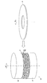
- FIG. 1A shows the appearance of the magnetic disk glass substrate 1 of the embodiment.
- a glass substrate 1 for a magnetic disk in the present embodiment is a donut-shaped thin glass substrate in which an inner hole 2 is formed.
- the size of the glass substrate for magnetic disks is not ask
- FIG. 1B is an enlarged view showing a cross section of an end portion on the outer peripheral side of the glass substrate for magnetic disk of the embodiment.
- the magnetic disk glass substrate includes a pair of main surfaces 1p, side wall surfaces 1t arranged along a direction orthogonal to the pair of main surfaces 1p, and a pair of main surfaces 1p and sides.
- each chamfered surface 1c has a pair of chamfered surfaces 1c arranged between the wall surface 1t.
- a side wall surface and a chamfered surface are similarly formed on the inner peripheral side end of the magnetic disk glass substrate.
- the angle (chamfer angle) formed by each chamfered surface 1c with respect to the side wall surface 1t is the same, for example, 40 to 50 degrees.
- the chamfer angle is typically 45 degrees as shown.
- the chamfered surface may be formed in an arc shape in a sectional view.
- the thickness of the magnetic disk glass substrate of the present embodiment is not particularly limited.
- a magnetic disk glass substrate having a nominal size of 2.5 inches for example, 0.8 mm, 0.635 mm
- a glass substrate for a magnetic disk having a nominal diameter of 3.5 inches it is, for example, 0.5 to 3.0 mm.
- an aluminum alloy substrate is used as the nonmagnetic substrate.
- FIG. 2 is a diagram showing a flow of an embodiment of a method for manufacturing a glass substrate for magnetic disk.
- a plate-shaped glass blank having a pair of main surfaces is formed (step S10).
- the formed glass blank is scribed to produce an annular glass substrate (step S20).
- a magnetic disk glass substrate (hereinafter simply referred to as a glass substrate) having a circular through hole at the center is obtained.
- shape processing is performed on the scribed glass substrate (step S30).
- step S40 the glass substrate is ground with fixed abrasive grains
- step S40 the end surface of the glass substrate is polished
- step S50 1st grinding
- step S60 Next, chemical strengthening is performed on the glass substrate after the first polishing (step S70).
- step S80 the second polishing is performed on the chemically strengthened glass substrate (step S80).
- a magnetic disk glass substrate that satisfies the required surface irregularities can be obtained.
- a circular glass substrate is produced from a glass blank by the process from a glass blank shaping
- step S10 Glass blank forming process
- a glass base plate having a predetermined shape that is a base of a magnetic disk glass substrate is cut out from the plate glass.
- a glass blank glass blank
- a glass base plate can also be manufactured not only using these methods but using well-known manufacturing methods, such as a downdraw method, a redraw method, and a fusion method.
- step S20 Scribe process
- the formed glass blank is subjected to a scribing process using a scriber to obtain an annular glass substrate in which circular inner holes are formed.
- An annular glass substrate can also be obtained by forming a circular inner hole on the glass blank using a core drill or the like.
- the shape processing includes chamfering (chamfering of the outer peripheral end surface and the inner peripheral end surface) for the end portion of the glass substrate after the scribe processing.
- a chamfering process is a shape process which chamfers with a diamond grindstone in the outer peripheral end surface and inner peripheral end surface of the glass substrate after a scribe process.
- the chamfering inclination angle is, for example, 40 to 50 degrees with respect to the main surface, and is preferably about 45 degrees.
- step S40 Precision grinding process
- the main surface of the glass substrate is ground using a double-side grinding machine having a known planetary gear mechanism with an upper surface plate, a lower surface plate, an internal gear, a carrier, and a sun gear. .
- the main surface on both sides of the glass substrate is ground while the outer peripheral end surface of the glass substrate is held in the holding hole provided in the holding member of the double-side grinding apparatus.
- the machining allowance by grinding is, for example, about several ⁇ m to 100 ⁇ m.
- the particle size of the fixed abrasive used for the fine grinding process is, for example, about 10 ⁇ m.
- the double-sided grinding apparatus has a pair of upper and lower surface plates (upper surface plate and lower surface plate), and a glass substrate is sandwiched between the upper surface plate and the lower surface plate.
- the glass substrate is sandwiched between the upper surface plate and the lower surface plate in a state where the glass substrate is held in a holding hole provided in the disk-shaped carrier. And by moving either the upper surface plate or the lower surface plate, or both, the glass substrate and each surface plate can be moved relatively to grind both main surfaces of the glass substrate. it can.
- step S50 End face polishing process
- a magnetic field is formed by using magnetic field generating means so that magnetic lines of force advance in the thickness direction of the glass substrate, and a magnetic functional fluid (hereinafter referred to as “polishing fluid”) containing abrasive grains in the magnetic field.
- the end surface of the glass substrate is polished by being held and moved relative to the polishing fluid in a state where the end surface of the glass substrate is in contact with the polishing fluid.
- the polishing fluid forms a lump in the magnetic field.
- the abrasive grains contained in the polishing fluid for example, fine particles such as cerium oxide and zirconium oxide are used.
- polishing is 10 micrometers or less, More preferably, it is 5 micrometers or less.
- the end surface polishing of this embodiment can be polished in a shorter time than the conventional end surface polishing method, for example, the conventional magnetic polishing method of polishing the end surface of the glass substrate with a polishing slurry using a brush. Efficiency is good. The end face polishing will be described later.
- step S60 Next, a first polishing process is performed on the main surface of the glass substrate.
- the main surfaces on both sides of the glass substrate are polished using a double-side polishing apparatus equipped with a planetary gear mechanism.
- loose abrasive grains such as cerium oxide abrasive grains or zirconia abrasive grains and a resin polisher are used.
- the first polishing removes cracks and distortions remaining on the main surface when, for example, fine grinding is performed.
- step S70 The glass substrate can be appropriately chemically strengthened.
- the chemical strengthening liquid for example, a molten liquid obtained by heating potassium nitrate, sodium nitrate, or a mixture thereof can be used. Then, by immersing the glass substrate in the chemical strengthening solution, lithium ions and sodium ions in the glass composition on the surface of the glass substrate are converted into sodium ions and potassium ions having relatively large ion radii in the chemical strengthening solution, respectively. By replacing each, a compressive stress layer is formed in the surface layer portion, and the glass substrate is strengthened. The timing of performing the chemical strengthening treatment can be determined as appropriate.
- the polishing treatment is performed after the chemical strengthening treatment, the foreign matter fixed to the surface of the glass substrate by the chemical strengthening treatment can be removed together with the smoothing of the surface. This is particularly preferable because it can be performed. Further, the chemical strengthening treatment may be performed as necessary, and may not be performed.
- step S80 Next, 2nd grinding
- the second polishing is intended for mirror polishing of the main surface.
- a double-side polishing apparatus having the same configuration as the double-side polishing apparatus used for the first polishing is used.
- the free abrasive grains used for the second polishing treatment for example, fine particles such as colloidal silica are used.
- the second polishing process is not necessarily an essential process, but it is preferable that the second polishing process is performed in that the level of surface irregularities on the main surface of the glass substrate can be further improved. Thereafter, by cleaning, a glass substrate for a magnetic disk is obtained. Note that the glass substrate is polished so that the arithmetic average roughness Ra of the surface roughness of the glass substrate after the second polishing treatment is 0.15 nm or less, thereby producing a glass substrate for a magnetic disk having a small surface roughness. This is preferable.
- FIG. 3 and FIG. 4 are diagrams for explaining a polishing method for end face polishing according to the present embodiment, and are diagrams for easy understanding.
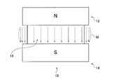
- the polishing apparatus 10 that performs end face polishing polishes the end face of the glass substrate using a magnetic field generating means and a polishing fluid. 3 and 4 illustrate polishing of the outer peripheral end face of the glass substrate. An outline of the polishing apparatus 10 that performs end face polishing will be described. As shown in FIG. 3, the polishing apparatus 10 includes a pair of magnets 12 (N poles) and magnets 14 (S poles) that are cylindrical permanent magnets, and a spacer 16.
- a magnetic field is formed around the spacer 16 from which magnetic lines of force are directed from the magnet 12 to the magnet 14.
- a pair of magnets arranged in the thickness direction of the glass substrate G so that the N-pole surface and the S-pole surface are spaced apart from each other is used as the magnetic field generating means.
- a spacer 16 made of a non-magnetic material is provided between the magnets 12 and 14 so that the separation distance between the N pole end face of the magnet 12 and the S pole end face of the magnet 14 is a predetermined distance. It is done.
- the glass substrate G to be end face polished is held by a rotating body (not shown) and rotated around the central axis.
- a magnetic field is formed so that the lines of magnetic force directed from the magnet 12 to the magnet 14 advance, and the outer peripheral end of the glass substrate G held by the rotating body is held in the magnetic fluid while the polishing fluid lump F is held in the magnetic field.
- the outer peripheral end surface of the glass substrate G is polished by repeatedly contacting the glass substrate G and the lump F of the polishing fluid by being brought into contact with F repeatedly.
- the lump F of the polishing fluid includes magnetic fine particles 5a and polishing abrasive grains 5b.
- the polishing apparatus 10 and a rotating body (not shown) that holds the glass substrate G are mechanically connected to a driving motor (not shown).
- a driving motor (not shown).
- the rotating directions of the polishing apparatus 10 and the rotating body that holds the glass substrate G are rotated in opposite directions, and the peripheral speed of the polishing apparatus 10 and the rotating body is rotated at 40 to 500 m / min. preferable.
- the polishing apparatus 10 is fixed, whereby the lump F of the polishing fluid is fixed, and the glass substrate G is rotated, so that the outer peripheral end surface of the glass substrate G and the lump F of the polishing fluid can be relatively moved. Good.
- a permanent magnet is used as the magnetic field generating means, but an electromagnet can also be used.
- a polishing fluid used for end face polishing for example, a nonpolar oil containing 3 to 5 g / cm 3 of magnetic fine particles containing Fe (iron) element having an average particle diameter (D50) of 0.1 to 10 ⁇ m, and a surfactant are used.
- the contained fluid is used.
- Nonpolar oil or polar oil has a viscosity of 100 to 1000 (mPa ⁇ sec) at room temperature (20 ° C.), for example. Since the polishing fluid becomes a lump F having relatively high elastic characteristics due to the magnetic field from the magnet 12 toward the magnet 14, the polishing fluid can be efficiently polished by pressing the end face of the glass substrate against the lump of polishing fluid. That is, the processing rate can be made higher than before, and polishing can be performed efficiently.
- abrasive grains contained in the polishing fluid known abrasive grains of glass substrates such as cerium oxide, colloidal silica, zirconia oxide, alumina abrasive grains, and diamond abrasive grains can be used.
- the average particle diameter (D50) of the abrasive grains is, for example, 0.5 to 10 ⁇ m. By using the abrasive grains in this range, the end face of the glass substrate can be satisfactorily polished.
- the abrasive grains are contained in the polishing fluid, for example, 3 to 15 [Vol%].
- the average particle size (D50) means a particle size at which the cumulative volume frequency calculated by the volume fraction is 50% calculated from the smaller particle size.
- the viscosity of the polishing fluid is preferably 1000 to 2000 [mPa ⁇ sec] at room temperature (20 ° C.), from the viewpoint of forming the lump F of the polishing fluid and performing the end face polishing efficiently.
- the viscosity is low, it is difficult to form the lump F, and it is difficult to perform polishing while being relatively moved while being pressed against the end face of the glass substrate G.
- the viscosity of the polishing fluid is excessively high, the lump F of the polishing fluid is formed along the shape of the edge of the glass substrate G during polishing, and it is difficult to form a uniform pressed state.
- the magnetic flux density of the magnetic field generated by the magnetic field generating means is preferably 0.3 to 0.9 [Tesla] from the viewpoint that the lump F of the polishing fluid is formed and the end face polishing is performed efficiently.
- the yield stress of the magnetic functional fluid is preferably 30 kPa or more, more preferably 30 to 60 kPa, with a 0.4 [Tesla] magnetic field applied.
- the yield stress (yield shear stress) of the polishing fluid can be determined by the following method, for example.
- a rotary viscometer that incorporates magnetic field generation means (permanent magnet, electromagnet, etc.) capable of applying a 0.4 [Tesla] magnetic field
- the yield stress of the magnetic functional fluid can be obtained by approximating the relationship between the obtained shear rate and the shear stress using a known Casson equation.
- the yield stress affects the pressure that the glass substrate receives from the polishing fluid, that is, shear stress, when the polishing fluid held by the magnetic field and the outer peripheral end surface of the glass substrate move relative to each other. Therefore, the higher the yield stress of the polishing fluid (the higher the shear stress when the polishing fluid flows), the more efficient polishing is achieved by contact between the abrasive grains and the glass substrate, and the end face polishing processing rate is improved. Can do.
- FIG. 5 is a diagram conceptually showing the lines of magnetic force when the outer peripheral end surface of the glass substrate G is being polished. During polishing of the end face of the glass substrate, a lump of polishing fluid contacts the end of the glass substrate G while rotating at a relatively high speed as the polishing apparatus 10 rotates, and a part of the lump is discharged to the outside little by little.
- the abrasive grains contained in the polishing fluid held by the magnetic field are also released to the outside.
- the abrasive grains contained in the polishing fluid are The reason why it is likely to be released to the outside (that is, the concentration of the abrasive grains in the polishing fluid decreases) will be described with reference to FIG.
- the edge of the glass substrate crosses the magnetic flux lines, so that the arrangement of the magnetic fine particles in the polishing fluid collapses, thereby locally reducing the holding power of the abrasive grains by the magnetic field, The abrasive grains are easily released to the outside.
- the polishing fluid in the region A1 having a high holding power by the magnetic field maintains a high concentration of the abrasive grains, but the holding power by the magnetic field.
- the concentration of polishing abrasive grains decreases.
- the side wall surface Co1 of the glass substrate G included in the region A1 does not decrease the processing rate even if the polishing is continuously performed, but the chamfered surfaces Co2 and Co3 of the glass substrate G included in the region A2 are continuous.
- polishing is performed, the amount of polishing abrasive grains in the polishing fluid decreases, and the processing rate decreases accordingly.
- the end surface polishing process of this embodiment is performed while supplying abrasive grains from the outside during polishing. That is, by supplying new abrasive grains from the outside to the area A2 in which the slurry concentration is likely to decrease in continuous processing in FIG. 5, the chamfered surface processing rate decreases when continuously performing end surface polishing. Can be suppressed.
- the supply of the abrasive grains during polishing may be performed by supplying the abrasive grains themselves, or may be performed by supplying a liquid containing the abrasive grains.
- Examples of the supply method include, but are not limited to, a method of flowing out abrasive grains or a liquid containing the abrasive grains toward the region A2 (for example, a method of spraying), a method of dropping, and the like.
- FIG. 6 shows an example in which the polishing fluid is supplied to the polishing apparatus 10 from the nozzle of the supply apparatus 30 in a plan view.
- the liquid containing the additional abrasive grains is supplied toward a position where the lump of polishing fluid held in the magnetic field and the outer peripheral end of the glass substrate G are in contact with each other.
- a liquid containing additional abrasive grains is supplied along the direction of movement of the end surface of the glass substrate in contact with the lump of polishing fluid.
- the liquid for example, water can be used.
- the supply timing of the liquid containing the additional abrasive grains is not particularly limited.
- the liquid may be supplied at any timing during the end surface polishing process, or after the polishing of the glass substrate is finished, the next glass is supplied. It may be supplied until the polishing of the substrate is started, or may be supplied at a timing between lots divided by a predetermined time or a predetermined number of glass substrates. Further, the supply may be continued without specifying a specific timing.
- magnetic fine particles or a magnetic functional fluid may be added to the liquid supplied during the end face polishing of the glass substrate G. Since the magnetic fine particles are gradually reduced by the polishing process, a decrease in the processing rate can be suppressed from a long-term viewpoint.
- the magnetic fine particles are much less likely to decrease than the abrasive grains, supplying the magnetic fine particles may gradually increase the amount of the magnetic fine particles contained in the polishing fluid during end face polishing. is there. In this case, magnetic fine particles that cannot be held in the magnetic field may scatter around the polishing apparatus and cause the substrate surface to become dirty. Therefore, it is necessary to adjust so that the supply amount of the magnetic fine particles and the magnetic functional fluid does not become excessive.
- the temperature of the polishing fluid supplied during the end surface polishing process, the polishing abrasive grains, or the liquid containing the polishing abrasive grains is preferably room temperature or lower. Specifically, it is 25 degrees or less, more preferably 20 degrees or less.
- frictional heat is generated to move the glass substrate G relative to the lump of polishing fluid across the magnetic field lines formed by the magnetic field generating means.
- the amount of moisture in the inside decreases, and the lubricity in the processed part deteriorates, which causes a minute scratch on the surface of the processed part. Therefore, by setting the temperature of the polishing fluid supplied during polishing to room temperature or lower, generation of the frictional heat can be suppressed, and the polishing quality of the workpiece can be maintained high.
- Modification 1 Although the polishing of the outer peripheral end face of the glass substrate G has been described with reference to FIGS. 3 to 6, the inner peripheral end face of the glass substrate can also be polished by the same method.
- Modification 1 (not shown) is an example in which the inner peripheral end face is polished simultaneously with the polishing of the outer peripheral end face of the glass substrate G.
- a polishing apparatus (not shown) having a configuration similar to that in FIG. 3 is disposed in the vicinity of the inner peripheral end surface of the glass substrate G, and a magnetic field is generated by a pair of N-pole and S-pole magnets. . By holding the polishing fluid by this magnetic field, a lump of polishing fluid is formed.
- the inner peripheral end face of the glass substrate G is polished.
- the additional polishing fluid is supplied toward a position where the lump of polishing fluid held in the magnetic field and the inner peripheral end of the glass substrate G are in contact with each other.
- the magnetic field generating means of Modification 1 is provided such that the magnets 12 and 14 shown in FIGS. 3 and 4 are provided on the outer peripheral side of the glass substrate G so that the magnetic lines of force (outer peripheral magnetic lines) advance in the thickness direction of the glass substrate G.
- a pair of magnets (N pole and S pole) are provided on the outer peripheral side means for generating a magnetic field, and the inner peripheral side of the glass substrate G (that is, the inner hole of the glass substrate G).
- Inner peripheral means for generating a magnetic field so that the inner peripheral magnetic field lines) travel.
- the polishing of the end face is performed by holding the lump of polishing fluid by the magnetic field formed by each of the inner peripheral means and the outer peripheral means, and bringing the inner peripheral end face and the outer peripheral end face of the glass substrate G into contact with the polishing fluid lump. Both the inner peripheral end face and the outer peripheral end face are polished simultaneously by relative movement in this state. Therefore, in the first modification, the outer peripheral end face of the glass substrate G shown in FIGS. 3 and 4 can be polished and simultaneously the inner peripheral end face can be polished, and efficient end face polishing can be realized. It is not essential to polish both the inner peripheral end face and the outer peripheral end face at the same time. That is, it is sufficient that at least one of the inner peripheral means and the outer peripheral means is provided. Further, even when both the inner peripheral means and the outer peripheral means are provided, both the inner peripheral end face and the outer peripheral end face are not polished at the same time, and the inner peripheral end face and the outer peripheral end face are polished in order. Good.
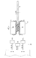
- FIG. 7 is a diagram showing a second modification example of polishing of the outer peripheral end face of the glass substrate G.
- FIG. Modification 2 is an example in which the inner peripheral end faces of a plurality of glass substrates are polished together instead of a single glass substrate.
- 7 includes N pole magnets 121, 122, 123, 124,..., S pole magnets 140, 141, 142, 143,... And spacers 161, 162, 163,. .
- Each of the N pole magnets, each S pole magnet, and each spacer has the same configuration as the magnet 12, the magnet 14, and the spacer 16 of FIG.
- the N pole end face of the magnet and the adjacent S pole end face are arranged in a stacked manner so as to face each other with a predetermined distance therebetween.
- a magnetic field is formed in which magnetic lines of force are directed from an N-pole magnet facing each other through a spacer to an S-pole magnet. That is, in the thickness direction of the glass substrate G, a plurality of pairs of magnets arranged in a state of being separated so that the N-pole surface and the S-pole surface face each other are used as the magnetic field generating means. For example, a magnetic field in which magnetic lines of force are directed from the magnet 121 to the magnet 141 is formed.
- the lump F of the polishing fluid is held by the magnetic field at the periphery of each of the spacers 161, 162, 163,.
- the polishing apparatus 10A is rotated as shown in FIG. 7 using a drive motor (not shown).
- the plurality of glass substrates G are integrated as a laminated body with an adhesive or the like with spacers 151, 152, 153, 154,.
- any adhesive may be used as the adhesive used to form the laminated body as long as the main surfaces of the plurality of glass substrates G can be bonded to the spacer or peeled from the spacer.
- an ultraviolet curable resin adhesive is easily solidified by irradiation with ultraviolet rays having a predetermined wavelength, the bonding operation is easy.
- the adhesive in addition to the UV curable resin adhesive, wax, photo curable resin, visible light curable resin, and the like can be used.
- a spacer may be sandwiched and pasted.
- a thin spacer such as a resin material, a fiber material, a rubber material, a metal material, or a ceramic material can be used.
- the laminated body including a plurality of glass substrates G is held by a rotating body (not shown) and rotated as shown in FIG. 7 using a driving motor (not shown).
- each glass substrate G included in the laminate is brought into contact with the polishing fluid lump F, whereby the polishing fluid lump F and the outer peripheral end faces of the plurality of glass substrates G are moved relative to each other, whereby a plurality of glasses is obtained.
- the outer peripheral end face of the substrate G can be polished simultaneously. That is, since the outer peripheral end surfaces of a plurality of glass substrates can be polished at the same time, the processing rate can be made higher than before and the polishing can be performed efficiently.
- the spacer provided between the magnets is adjusted so that the intervals between the glass substrates G and the lumps of the polishing fluid lumps coincide with each other and the outer peripheral end surfaces of the glass substrates G are simultaneously in contact with the lumps of lapping fluids F, respectively. By doing so, it is preferable to adjust the formation position of the lump F of the polishing fluid.
- the laminate of the plurality of magnets and the glass substrate G is in the direction of lamination of the laminate during polishing. It is preferable to swing relatively.
- each of the lumps F of polishing fluid can be contacted without any deviation during polishing, and the outer peripheral end surfaces of the plurality of glass substrates G can be polished uniformly.
- This swinging is not only used for polishing the end face of the laminated body of glass substrates of the second modification, but can also be applied to the case where the end face of one glass substrate as shown in FIG. 4 is polished.
- the end face polishing process of the modified example 2 it is performed while supplying a liquid containing abrasive grains from the outside during polishing.
- the abrasive grains lost during the polishing process can be supplemented, and a reduction in the chamfered surface processing rate can be suppressed when end face polishing is performed continuously.
- the additional polishing fluid is supplied from the nozzle of the supply device 30 ⁇ / b> A toward a position where the polishing fluid lump F held in the magnetic field and the outer peripheral end of the glass substrate G contact each other.
- the liquid containing the abrasive grains falls from the upper side to the lower side, the liquid is supplied to a plurality of lumps F of the polishing fluid that are in contact with the outer peripheral ends of the glass substrates.
- the abrasive grains are included in the lateral direction from each of the plurality of nozzles toward the position where the lump F of each polishing fluid and the outer peripheral end of the glass substrate G contact each other.
- a liquid may be supplied.
- FIG. 7 illustrates the case where the outer peripheral end surfaces of the plurality of glass substrates G integrated as a laminate are polished, the inner peripheral end surfaces of the plurality of glass substrates G may be similarly polished. Moreover, you may grind
- FIG. 8 is a diagram showing a third modification of the end surface polishing.
- the same polishing apparatus 10 as in FIG. 4 is used, but both the polishing apparatus 10 and the glass substrate G to be polished are immersed in a bath 90 filled with a liquid containing polishing abrasive grains. Then, the end surface of the glass substrate G is polished.
- the concentration of the abrasive grains in the tank may be the same value as described in the embodiment, but may be, for example, 1 to 50 wt%. For example, water can be used as the liquid.
- the tank 90 as in FIG.
- a magnetic field is formed so that the magnetic lines of force from the magnet 12 toward the magnet 14 are advanced, and the polishing fluid around the magnetic field is held as a lump F by the magnetic field.
- the outer peripheral end of the glass substrate G is polished by repeatedly bringing the outer peripheral end of the glass substrate G into contact with the polishing fluid mass F and moving the glass substrate G and the polishing fluid mass F relative to each other. At this time, as described above, in a part of the region (region A2 in FIG. 5), the end of the glass substrate crosses the magnetic flux lines, so that the arrangement of the magnetic fine particles in the polishing fluid collapses, thereby causing a magnetic field. Since the holding power of the abrasive grains is locally reduced, the abrasive grains are easily released to the outside.
- FIG. 8 illustrates the case where the outer peripheral end surface of one glass substrate G is ground in the polishing fluid bath 90, but is not limited thereto.
- the inner peripheral end face of the glass substrate G may be polished in the polishing fluid bath 90, or the end faces of the laminate of the plurality of glass substrates G may be polished as shown in the second modification.
- Example 10 In order to confirm the effect of the present invention, end face polishing of the produced glass substrate was performed.
- the produced glass substrate has an outer diameter of 65 mm and a thickness of 0.8 mm.
- a chamfer of 0.15 mm in the thickness direction of the glass substrate is inclined at 45 degrees with respect to the main surface. gave.
- the polishing fluid used for polishing the outer peripheral end surface of the glass substrate is 3 [g / cm 3 ] of fine particles of Fe (iron) having an average particle diameter (D50) of 2 ⁇ m dispersed in non-magnetic oil (silicon oil).
- abrasive grains in which cerium oxide having an average particle diameter of 2 ⁇ m was dispersed were used.
- the concentration of cerium oxide in the polishing fluid was included to be 5 [vol%].
- a permanent magnet having a magnetic flux density of 0.5 [Tesla] was used as the magnet.
- Example 1 In addition to the polishing conditions of the comparative example, polishing was performed while supplying a liquid containing abrasive grains. Specifically, as shown in FIG. 6, the polishing of the outer peripheral end surface of one glass substrate is finished with a liquid containing abrasive grains along the moving direction of the end surface of the glass substrate in contact with the lump of polishing fluid. Supplied every time. The liquid was water. As in the comparative example, 100 glass substrates were polished, and the processing time for each sheet was 3 minutes.
- Example 1 As shown in Table 1, in Example 1, when the glass substrate was continuously polished, it was confirmed that the reduction in the processing rate was greatly suppressed as compared with the comparative example. Although not shown in Table 1, the rate of reduction of the processing rate on the side wall surface was 2% or less in both the comparative example and Example 1, which was a level that does not cause a problem.
- Example 2 The outer peripheral end face of the glass substrate was polished in the same manner as in the comparative example except that the liquid containing the abrasive grains was continuously supplied to the lump of polishing fluid continuously during the polishing process. At this time, the liquid was dropped from above onto the lump of polishing fluid immediately before reaching the polishing portion (processing point). As a result, the reduction rate of the processing rate on the chamfered surface of the glass substrate was 5%, and a better result than Example 1 was obtained. In addition, the reduction rate of the processing rate in the side wall surface of a glass substrate was 2% or less similarly to Example 1.
- Example 3 As shown in FIG. 8, the outer peripheral end face of the glass substrate was polished in a state where the glass substrate to be polished was immersed in a tank filled with a liquid containing abrasive grains.
- the liquid in the tank was water, and the abrasive grain concentration was 20 wt%. During the polishing, the liquid was not supplied into the tank. As a result, the reduction rate of the processing rate on the chamfered surface of the glass substrate was 0%, and a result better than that of Example 2 was obtained.
- the processing rate of the chamfered surface is increased.
- a process of correcting the shape of the lump of the polishing fluid is performed so as not to greatly decrease.
- the reason why the processing rate of the chamfered surface is lowered when the shape of the polishing fluid is not corrected in the end surface polishing of the glass substrate will be described with reference to FIG. 9, in the state S1, which is the initial state of the end surface polishing process, the lump F of the polishing fluid is stably held by the magnetic field formed by the magnets 12 and 14.
- the side wall surface and the chamfered surface constituting the outer peripheral end surface of the glass substrate G are pressed from the lump F with a constant pressing force, Both chamfered surfaces are in a high processing rate.
- the processing rate of the side wall surface hardly decreases, but the processing rate of the chamfered surface greatly decreases. That is, the side wall surface of the outer peripheral end surface of the glass substrate is polished by the lump F of the polishing fluid in the region A1 where the glass substrate G does not cross the lines of magnetic force in plan view.
- the lump F of the polishing fluid in the region A1 has a high holding force of the lump F due to the magnetic field because the lines of magnetic force are not cut off, and the polishing is performed stably by the abrasive grains, so that the polishing processing rate is high.
- the chamfered surface of the outer peripheral end surface of the glass substrate is polished by the lump F of the polishing fluid in the region A2 where the glass substrate G crosses the magnetic field lines in plan view.
- the lump F of the polishing fluid in this area A2 has a relatively weak holding force due to the magnetic field.
- FIG. 10 is a diagram illustrating a configuration example when the shape of the polishing fluid is corrected using the shape correcting device.
- FIG. 11 is a diagram for explaining the shape correction processing of the polishing fluid using the shape correction device.
- the shape correcting device 20 includes jigs 21U, 21L, and 22 that are made of a non-magnetic material and are arcuate in plan view, and drive mechanisms (not shown) that drive the jigs.
- a driving mechanism (not shown) drives the jig 21U and the jig 21L in the horizontal direction and the vertical direction so that the jig 21U and the jig 21L can move on the surfaces of the magnet 12 and the magnet 14, respectively.
- the driving mechanism drives the jig 22 in the horizontal direction so that the jig 22 can be inserted into the space between the magnet 12 and the magnet 14.
- the length of the jig 22 in the thickness direction of the glass substrate is preferably set to be the same as or slightly lower than the distance between the magnet 12 and the magnet 14. Note that the jig 21U and the jig 21L may not be provided in the shape correction device 20 depending on the degree of shape correction of the polishing fluid.
- step S1 in a series of processes (steps S1 to S3) for correcting the shape of the lump F of the polishing fluid by the shape correcting device 20, the positional relationship between the jigs of the shape correcting device 20 and the magnets 12 and 14 is shown in the side view. It is shown by a figure and a plan view. In the example shown in FIG. 11, it is assumed that the jig 22 has already been positioned in the vertical direction.
- step S1 the jigs 21U and 21L are driven in the horizontal direction, and the jigs contact the side surfaces of the magnets 12 and 14, respectively.
- step S2 the jig 21U is driven downward, and the jig 21L is driven upward.
- step S3 the polishing fluid sticking out from the side surfaces of the magnets 12 and 14 (that is, a part of the deformed polishing fluid mass F) is pressed and moved to a position between the magnets 12 and 14 in a side view. Be made.
- step S3 the jig 22 is driven in the horizontal direction, and the polishing fluid moved in step S2 or the polishing fluid moved to the peripheral edge of each magnet due to deformation of the lump F is pressed by the jig 22. Is moved toward the center of the magnet.
- the shape of the deformed polishing fluid lump F is corrected so as to keep the pressing force against the glass substrate constant.
- the jig 21U and the jig 21L may not be used.
- the shape correcting device 20 is used to correct the shape of the lump F of the polishing fluid deformed by contact with the glass substrate so as to return to the original shape.
- the shape of the lump of the polishing fluid F is changed by bringing the jig into contact with the lump F of the polishing fluid. Thereby, the pressing force on the glass substrate is kept constant.
- the jig is brought into contact with the lump F of the polishing fluid so that the tip of the jig is inserted into the lump F of the polishing fluid.
- a jig having a convex cross section at the tip is used, and the tip of the jig is inserted into the lump F of polishing fluid by driving the jig in the horizontal direction.
- the shape of the jig may be a rod shape, a plate shape, a flat shape, or a prism shape. That is, the cross section of the tip of the jig may be circular or elliptical, flat, or polygonal.
- the height of such a jig in the vertical direction may be less than or equal to the gap between the magnets 12 and 14.
- the material of the jig is preferably a non-magnetic and relatively hard material such as a metal such as aluminum or titanium or ceramic.
- the lump F of the polishing fluid collapses and deforms (plastically deforms) in the region A2, and the pressing force against the chamfered surface on the outer peripheral side of the glass substrate G decreases.
- the density of the magnetic fine particles is uneven within the fluid mass. That is, in the area A1 in FIG. 9, the magnetic fine particles are dense due to the substrate being pushed in, and in the area A2, the density is low, thereby reducing the holding power of the abrasive grains in the area A2. It is thought that.
- the timing for correcting the shape of the lump of the polishing fluid may be any time as long as it is during the end face polishing process.
- the shape correcting device 20 is arranged on the opposite side of the glass substrate G that is a workpiece, so that the polishing fluid lump can be obtained while polishing the end surface of the glass substrate G.
- Shape correction can be performed. Further, the shape correction may be performed after the end surface polishing of the glass substrate is completed until the end surface polishing of the next glass substrate is started, or timing between lots divided by a predetermined time or a predetermined number of glass substrates. The shape may be corrected by.
- FIG. 12 shows an example in which the polishing fluid is supplied to the polishing apparatus 10 from the nozzle of the supply apparatus 30 in a plan view.
- the additional polishing fluid is supplied toward a position where the lump of polishing fluid held in the magnetic field and the outer peripheral end of the glass substrate G are in contact with each other. More preferably, it is supplied to a lump of polishing fluid at a position after contact with the part. More preferably, additional polishing fluid is supplied along the direction of movement of the end face of the glass substrate in contact with the lump of polishing fluid. This additional polishing fluid is newly held in the magnetic field as a lump, and as a result, the shape of the lump of polishing fluid is modified so as to maintain a constant pressing force on the glass substrate.
- the supply timing of the additional polishing fluid is not particularly limited.
- the additional polishing fluid may be supplied at an appropriate time during the end surface polishing process, or the end surface polishing of the next glass substrate starts after the end surface polishing of the glass substrate is completed. It may be supplied until it is done, or may be supplied at a predetermined time or at a timing between lots divided by a predetermined number of glass substrates. Further, the supply may be continued without specifying a specific timing.
- the temperature of the polishing fluid supplied during the end surface polishing treatment is room temperature or lower.
- frictional heat is generated to move the glass substrate G relative to the lump of polishing fluid so as to cross the magnetic field lines formed by the magnetic field generating means. This frictional heat is generated by the polishing fluid.
- the polishing processing rate is lowered. Therefore, by setting the temperature of the polishing fluid supplied during polishing to room temperature or less, generation of the frictional heat can be suppressed and the polishing processing rate can be kept high.
- Modification 1 Although the polishing of the outer peripheral end surface of the glass substrate G has been described with reference to FIGS. 9 to 12, the inner peripheral end surface of the glass substrate can also be polished by the same method. Modification 1 (not shown) is an example of polishing the inner peripheral end face simultaneously with the polishing of the outer peripheral end face of the glass substrate G, and is the same polishing method as the first modification of the first embodiment. The explanation is omitted.
- the additional polishing fluid is directed toward the position where the lump of polishing fluid held in the magnetic field and the inner peripheral end of the glass substrate G are in contact with each other by the supply device.
- the shape of the lump of the polishing fluid for polishing the inner peripheral end face is corrected so as to keep the pressing force against the glass substrate constant.
- the shape of the polishing fluid lump for polishing the outer peripheral end face is obtained by correcting the shape of the polishing fluid lump by the shape correcting device described above or by supplying an additional polishing fluid. Then, the pressing force on the glass substrate is corrected to be kept constant. Therefore, in this modification, it is possible to suppress a decrease in the processing rate of the inner peripheral side chamfered surface and the outer peripheral side chamfered surface while simultaneously polishing both the inner peripheral end surface and the outer peripheral end surface.
- FIG. 13 is a diagram illustrating a second modification example of polishing of the outer peripheral end surface of the glass substrate G.
- FIG. Modification 2 is an example in which the outer peripheral end surfaces of a plurality of glass substrates are polished together instead of a single glass substrate.
- a polishing apparatus 10A shown in FIG. 13 includes N-pole magnets 121, 122, 123, 124,..., S-pole magnets 140, 141, 142, 143,... And spacers 161, 162, 163,. .
- Each of the N pole magnets, each S pole magnet, and each spacer has the same configuration as the magnet 12, the magnet 14, and the spacer 16 of FIG.
- the N pole end face of the magnet and the adjacent S pole end face are arranged in a stacked manner so as to face each other with a predetermined distance therebetween.
- a magnetic field is formed in which magnetic lines of force are directed from an N-pole magnet facing each other through a spacer to an S-pole magnet. That is, in the thickness direction of the glass substrate G, a plurality of pairs of magnets arranged in a state of being separated so that the N-pole surface and the S-pole surface face each other are used as the magnetic field generating means. For example, a magnetic field in which magnetic lines of force are directed from the magnet 121 to the magnet 141 is formed.
- the lump F of the polishing fluid is held by the magnetic field at the periphery of each of the spacers 161, 162, 163,.
- the polishing apparatus 10A is rotated as shown in FIG. 13 using a drive motor (not shown).
- the plurality of glass substrates G are integrated as a laminated body with an adhesive or the like with spacers 151, 152, 153, 154,.
- the adhesive used for forming the laminate may be the same as that described in the second modification of the first embodiment.
- the laminated body including a plurality of glass substrates G is held by a rotating body (not shown) and rotated as shown in FIG. 13 using a driving motor (not shown).
- each glass substrate G included in the laminate is brought into contact with the polishing fluid lump F, whereby the polishing fluid lump F and the outer peripheral end faces of the plurality of glass substrates G are moved relative to each other, whereby a plurality of glasses is obtained.
- the outer peripheral end face of the substrate G can be polished simultaneously. That is, since the outer peripheral end surfaces of a plurality of glass substrates can be polished at the same time, the processing rate can be made higher than before and the polishing can be performed efficiently.
- the technical matters described in the second modification of the first embodiment for example, adjustment of spacers between magnets and swinging of a laminate of a plurality of magnets and a glass substrate G) are the same in this modification. Is also applicable.
- the polishing process is performed while supplying a new polishing fluid from the outside during polishing.
- additional polishing fluid from each of the plurality of nozzles 301, 302, 303,... Toward the position where the lump F of each polishing fluid and the outer peripheral edge of the glass substrate G contact each other. Supplied.
- the additional polishing fluid is newly held in the magnetic field as a lump, and as a result, the shape of each lump F of the polishing fluid is corrected so as to keep the pressing force against each glass substrate constant.
- FIG. 13 illustrates the case where the outer peripheral end surfaces of the plurality of glass substrates G integrated as a laminate are polished, but the inner peripheral end surfaces of the plurality of glass substrates G may be similarly polished. Moreover, you may grind
- Example 10 In order to confirm the effect of the present invention, end face polishing of the produced glass substrate was performed.
- the produced glass substrate has an outer diameter of 65 mm and a thickness of 0.8 mm.
- a chamfer of 0.15 mm in the thickness direction of the glass substrate is inclined at 45 degrees with respect to the main surface. gave.
- the outer peripheral edge of a glass substrate for a 2.5 inch type magnetic disk was inserted into a polishing apparatus in which a pair of magnets were spaced apart by a nonmagnetic stainless steel spacer. The dimensions of the magnet were 19 mm in diameter and 15 mm in thickness. Then, a polishing fluid was applied between the magnets to hold the mass of the magnet slurry in the magnetic field formed by the magnets, and the outer peripheral end surface of the glass substrate was polished. The end surface of the glass substrate and the polishing apparatus were rotated so as to be opposite to each other, and the number of rotations was set to 700 rpm. 100 glass substrates were polished, and the processing time for each one was 3 minutes.
- the polishing fluid used for polishing the outer peripheral end surface of the glass substrate is 3 [g / cm 3 ] of fine particles of Fe (iron) having an average particle diameter (D50) of 2 ⁇ m dispersed in non-magnetic oil (silicon oil).
- D50 average particle diameter
- SiO oil non-magnetic oil
- abrasive grains in which cerium oxide having an average particle diameter of 1.5 ⁇ m was dispersed were used.
- the concentration of cerium oxide in the polishing fluid was 7 [vol%].
- a permanent magnet having a magnetic flux density of 0.5 [Tesla] was used as the magnet.
- Example 1 As in the comparative example, 100 glass substrates were polished, and the processing time for each sheet was 3 minutes. In Example 1, polishing was performed under the same conditions as the polishing conditions of the comparative example except that the shape of the lump of deformed polishing fluid was corrected using a shape correction device every time 10 glass substrates were polished. .
- Example 2 A glass substrate under the same conditions as in the above comparative example except that a rod-shaped aluminum jig having a convex cross section was used and the tip of the jig was inserted into a lump of polishing fluid during end face polishing. The outer peripheral end face of was ground. As a result, the reduction rate of the processing rate on the chamfered surface of the glass substrate was 1%, which was better than that of Example 1.
- Example 3 Instead of using the shape correcting device, a polishing fluid was added during the polishing process to polish the outer peripheral end surface of the glass substrate. In this case, the reduction rate of the processing rate on the chamfered surface of the glass substrate was 6%.
- Example 4 In addition to the conditions of Example 1, polishing was performed while supplying a liquid containing abrasive grains. Specifically, as shown in FIG. 6, the polishing of the outer peripheral end surface of one glass substrate is finished with a liquid containing abrasive grains along the moving direction of the end surface of the glass substrate in contact with the lump of polishing fluid. Supplied every time. The liquid was water. In this case, the reduction rate of the processing rate on the chamfered surface of the glass substrate was 0%, which was even better than Example 2.
- the curvature radius of the shape of the part between a side wall surface and a chamfering surface was measured about 100 glass substrates of grinding
- R is the radius of a circle C2 that forms the curvature of the shape of the portion between the side wall surface 1t and the chamfered surface 1c, and is the curvature radius of the shape of the portion.
- the curvature radius R can be determined as follows, for example.
- P1 be the intersection of an imaginary line L1 extending the straight line portion of the chamfered surface 1c and a virtual line L2 extending the straight line portion of the side wall surface 1t.
- an imaginary line L3 passing through the intersection point P1 and extending perpendicularly to the straight line portion of the chamfered surface 1c is set.
- an intersection between the portion between the side wall surface 1t and the chamfered surface 1c and the virtual line L3 is defined as P2.
- a circle C1 having a predetermined radius (for example, 50 ⁇ m) around the intersection P2 is set.
- the radius of curvature is measured for each of the 100 glass substrates (the average value for each arbitrary point on the circumference on both sides), and the variation in 100 sheets (here, defined as the difference between the maximum value and the minimum value).
- the ratio of the variation size of Example 4 to the variation size of Example 1 was 0.5, which was significantly reduced. This is because not only the decrease in the polishing rate of the chamfered surface is suppressed but also the polishing of the portion between the side wall surface and the chamfered surface is stabilized by the synergistic effect by supplying the liquid containing abrasive grains. This is presumed to be due to this. That is, since the portion between the side wall surface and the chamfered surface is pointed, generally the shape of the portion is likely to fluctuate even by a slight change in the processing conditions, but in Example 4, the fluctuation was suppressed. I was able to confirm.
- substrate of this invention was demonstrated in detail, this invention is not limited to the said embodiment and modification, In the range which does not deviate from the main point of this invention, various improvement and a change are carried out. Of course, it is good.
- the manufacturing method of the glass substrate for magnetic disks was demonstrated as one Embodiment of the manufacturing method of the nonmagnetic board
Landscapes
- Engineering & Computer Science (AREA)
- Chemical & Material Sciences (AREA)
- Ceramic Engineering (AREA)
- Inorganic Chemistry (AREA)
- Mechanical Engineering (AREA)
- Manufacturing & Machinery (AREA)
- Manufacturing Of Magnetic Record Carriers (AREA)
- Finish Polishing, Edge Sharpening, And Grinding By Specific Grinding Devices (AREA)
- Grinding And Polishing Of Tertiary Curved Surfaces And Surfaces With Complex Shapes (AREA)
- Surface Treatment Of Glass (AREA)
Abstract
Description
ハードディスク装置に用いる磁気ヘッドにおいては、磁気ディスクの表面に微小な凹凸があると、公知のサーマルアスペリティ(Thermal Asperity)障害を生じ、再生に誤動作を生じ、あるいは再生が不可能になる虞がある。このサーマルアスペリティ障害の原因は、ガラス基板上の異物によって磁気ディスクの表面に形成された凸部が磁気ディスクの高速回転によりヘッドの近傍の空気の断熱圧縮および断熱膨張を発生させ、磁気ヘッドが発熱することに起因する。すなわち、サーマルアスペリティ障害は、磁気ヘッドが磁気ディスクに接触しない場合においても発生し得る。
したがって、このサーマルアスペリティ障害を防止するためには、磁気ディスクの表面は、極めて平滑で、かつ、異物の無い高清浄化された面に仕上げておく必要がある。
そのため、磁気ディスク用ガラス基板を製造するときには、円形状のガラス基板の主表面と側壁面に間に面取面を形成し、さらに側壁面と面取面とを研磨する処理が行われている。
しかし、上記端面研磨処理を多くのガラス基板を対象として枚葉式の処理により連続的に行った場合には、特に面取面の加工レートが次第に低下していくことがわかった。この問題は、ガラス基板に限らず他の材料(例えば、アルミニウム合金)を用いた非磁性基板についても同様に発生すると考えられる。
前記端面研磨処理は、磁場発生手段を用いて前記基板の厚さ方向に磁力線が進むように磁場を形成し、当該磁場に研磨砥粒を含む磁気機能性流体を保持させた状態で、前記基板の端面と前記磁気機能性流体とを接触させて、基板と前記磁気機能性流体とを相対移動させることにより、前記基板の端面を研磨する処理である。ここで、端面研磨処理中に前記磁気機能性流体に対して前記研磨砥粒を供給することを特徴とする。
なお、磁気機能性流体は、磁場に応答する機能性流体であればよく、例えばMRF(磁気粘性流体;Magneto-rheological Fluid)、MF(磁性流体;Magnetic Fluid)、MCF(磁気混合流体;Magnetic Compound Fluid)などであってもよい。
前記端面研磨処理は、研磨砥粒を含む磁気機能性流体と前記基板を、研磨砥粒を含む液体に浸漬させた状態で、磁場発生手段を用いて前記基板の厚さ方向に磁力線が進むように磁場を形成し、当該磁場に研磨砥粒を含む磁気機能性流体を保持させた状態で、前記基板の端面と前記磁気機能性流体とを接触させて、基板と前記磁気機能性流体とを相対移動させることにより、前記基板の端面を研磨することを特徴とする。
前記端面研磨処理は、磁場発生手段を用いて前記基板の厚さ方向に磁力線が進むように磁場を形成し、当該磁場に研磨砥粒を含む磁気機能性流体を保持させることによって前記磁気機能性流体の塊を形成し、前記基板の端面と前記磁気機能性流体の塊とを接触させて、基板と前記磁気機能性流体の塊とを相対移動させることにより、前記基板の端面を研磨する処理である。ここで、基板と接触することにより変形した磁気機能性流体の塊の形状を、基板に対する押圧力を一定に維持するように修正することを特徴とする。
前記端面研磨処理は、磁場発生手段を用いて前記基板の厚さ方向に磁力線が進むように磁場を形成し、当該磁場に研磨砥粒を含む磁気機能性流体を保持させることによって前記磁気機能性流体の塊を形成し、前記基板の端面と前記磁気機能性流体の塊とを接触させて、基板と前記磁気機能性流体の塊とを相対移動させることにより、前記基板の端面を研磨する処理であり、
前記基板と接触することにより変形した磁気機能流体の塊の形状を、元の形状に戻すように修正することを特徴とする。
前記端面研磨処理は、磁場発生手段を用いて前記基板の厚さ方向に磁力線が進むように磁場を形成し、当該磁場に研磨砥粒を含む磁気機能性流体を保持させることによって前記磁気機能性流体の塊を形成し、前記基板の端面と前記磁気機能性流体の塊とを接触させて、基板と前記磁気機能性流体の塊とを相対移動させることにより、前記基板の端面を研磨する処理であり、
前記磁気機能流体の塊に治具を接触させることで前記磁気機能流体の塊の形を変えることを特徴とする。
以下、本発明の非磁性基板の製造方法の一実施形態として、磁気ディスク用基板の製造方法について詳細に説明する。なお、以下の説明では、磁気ディスク用基板としてガラス基板を用いる場合について説明するが、それに限られずアルミニウム合成基板であってもよい。
[磁気ディスク用ガラス基板]
本実施形態における磁気ディスク用ガラス基板の材料として、アルミノシリケートガラス、ソーダライムガラス、ボロシリケートガラスなどを用いることができる。特に、化学強化を施すことができ、また主表面の平坦度および基板の強度において優れた磁気ディスク用ガラス基板を作製することができるという点で、アルミノシリケートガラスを好適に用いることができる。
また、酸化物基準の質量%で、SiO2:45.60~60%、およびAl2O3:7~20%、およびB2O3:1.00~8%未満、およびP2O5:0.50~7%、およびTiO2:1~15%、およびROの合計量:5~35%(ただしRはZnおよびMg)の各成分を含有し、CaOの含有量が3.00%以下、BaOの含有量が4%以下であり、PbO成分、As2O3成分およびSb2O3成分およびCl-、NO-、SO2-、F-成分を含有せず、主結晶相としてRAl2O4、R2TiO4、(ただしRはZn、Mgから選択される1種類以上)から選ばれる一種以上を含有し、主結晶相の結晶粒径が0.5nm~20nmの範囲であり、結晶化度が15%以下であり、比重が2.95以下であることを特徴とする結晶化ガラスであってもよい。
図1Bは、実施形態の磁気ディスク用ガラス基板の外周側の端部の断面を拡大して示す図である。図1Bに示すように、磁気ディスク用ガラス基板は、一対の主表面1pと、一対の主表面1pに対して直交する方向に沿って配置された側壁面1tと、一対の主表面1pと側壁面1tとの間に配置された一対の面取面1cとを有する。図示しないが、磁気ディスク用ガラス基板の内周側の端部についても同様に、側壁面と面取面が形成されている。側壁面1tを基準として各面取面1cのなす角度(面取り角)は同一であり、例えば40~50度である。面取り角は典型的には図示するように45度である。なお、面取面は、断面視において円弧状に形成されていてもよい。
次に、図2を参照して、磁気ディスク用ガラス基板の製造方法のフローを説明する。図2は、磁気ディスク用ガラス基板の製造方法の一実施形態のフローを示す図である。
図2に示すように、先ず、一対の主表面を有する板状のガラスブランクを成形する(ステップS10)。次に、成形されたガラスブランクをスクライブして、円環状のガラス基板を作製する(ステップS20)。これにより、中心部分に円孔の貫通孔を有する磁気ディスク用ガラス基板(以降単にガラス基板という)が得られる。次に、スクライブされたガラス基板に対して形状加工(チャンファリング加工)を行う(ステップS30)。次に、ガラス基板に対して固定砥粒による研削を施す(ステップS40)。次に、ガラス基板の端面研磨を行う(ステップS50)。次に、ガラス基板の主表面に第1研磨を施す(ステップS60)。次に、第1研磨後のガラス基板に対して化学強化を施す(ステップS70)。次に、化学強化されたガラス基板に対して第2研磨を施す(ステップS80)。以上の処理を経て、要求された表面凹凸を満足する磁気ディスク用ガラス基板が得られる。なお、ガラスブランク成形処理(ステップS10)から形状加工処理(ステップS30)までの処理により、ガラスブランクから円形状のガラス基板が作製される。以下、各処理について、詳細に説明する。
例えばフロート法によって板状ガラスを形成した後、この板状ガラスから、磁気ディスク用ガラス基板の元となる所定形状のガラス素板が切り出される。フロート法の代わりに、例えば上型と下型を用いたプレス成形によってガラス素板(ガラスブランク)を成形してもよい。なお、ガラス素板は、これらの方法に限らず、ダウンドロー法、リドロー法、フュージョン法などの公知の製造方法を用いて製造することもできる。
なお、ガラス素板の両主表面に対して、必要に応じて、粗研削処理を行ってもよい。
次に、スクライブ処理について説明する。ガラスブランク成形処理の後、スクライブ処理では、成形されたガラスブランクに対してスクライバを用いたスクライブ処理が行い、円形状の内孔が形成された円環状のガラス基板が得られる。なお、ガラスブランクに対してコアドリル等を用いて円形状の内孔を形成することにより円環状のガラス基板を得ることもできる。
次に、形状加工処理について説明する。形状加工処理では、スクライブ処理後のガラス基板の端部に対するチャンファリング加工(外周端面および内周端面の面取り加工)を含む。チャンファリング加工は、スクライブ処理後のガラス基板の外周端面および内周端面において、ダイヤモンド砥石により面取りを施す形状加工である。面取りの傾斜角度は、主表面に対して例えば40~50度であり、略45度であることが好ましい。この形状加工によって、所定の断面形状をしたガラス基板が作製される。
精研削処理では、上定盤、下定盤、インターナルギヤ、キャリヤ、太陽ギヤを備えた公知の遊星歯車機構を持った両面研削装置を用いて、ガラス基板の主表面に対して研削加工を行う。具体的には、ガラス基板の外周端面が、両面研削装置の保持部材に設けられた保持孔内に保持されながらガラス基板の両側の主表面の研削が行われる。研削による取り代は、例えば数μm~100μm程度である。精研削処理に用いられる固定砥粒の粒子サイズは、例えば10μm程度である。両面研削装置は、上下一対の定盤(上定盤および下定盤)を有しており、上定盤および下定盤の間にガラス基板が狭持される。ガラス基板の挟持は、円板状のキャリヤに設けられた保持孔にガラス基板が保持された状態で、キャリヤが上定盤および下定盤の間に挟まれる。そして、上定盤または下定盤のいずれか一方、または、双方を移動操作させることで、ガラス基板と各定盤とを相対的に移動させることにより、ガラス基板の両主表面を研削することができる。
次に、端面研磨処理を説明する。端面研磨では、磁場発生手段を用いてガラス基板の厚さ方向に磁力線が進むように磁場を形成し、当該磁場に研磨砥粒を含む磁気機能性流体(以下、「研磨流体」という。)を保持させ、ガラス基板の端面を研磨流体と接触させた状態で研磨流体に対して相対移動させることにより、ガラス基板の端面を研磨する。研磨流体は、磁場において塊を形成している。研磨流体に含まれる研磨砥粒として、例えば、酸化セリウムや酸化ジルコニウム等の微粒子が用いられる。また、端面研磨による取り代は、10μm以下であり、より好ましくは5μm以下である。端面研磨を行うことにより、ガラス基板の端面での塵埃等が付着した汚染、傷等の損傷の除去を行うことにより、サーマルアスペリティ障害の発生の防止や、ナトリウムやカリウム等のコロージョンの原因となるイオン析出の発生を防止することができる。本実施形態の端面研磨は、従来の端面研磨の方式、例えばブラシを用いて研磨スラリでガラス基板の端面を研磨する従来の磁気研磨の方式に比べて短時間に研磨することができ、極めて生産効率がよい。端面研磨については後述する。
次に、ガラス基板の主表面に第1研磨処理が施される。第1研磨処理では、遊星歯車機構を備えた両面研磨装置を用いてガラス基板の両側の主表面に対して研磨を行う。第1研磨処理では、例えば、酸化セリウム砥粒、あるいはジルコニア砥粒などの遊離砥粒と、樹脂ポリッシャが用いられる。第1研磨によって、例えば精研削処理を行った場合に主表面に残留したクラックや歪みを除去する。
ガラス基板は適宜化学強化することができる。化学強化液として、例えば硝酸カリウム,硝酸ナトリウム、またはそれらの混合物を加熱して得られる溶融液を用いることができる。そして、ガラス基板を化学強化液に浸漬することによって、ガラス基板の表層にあるガラス組成中のリチウムイオンやナトリウムイオンが、それぞれ化学強化液中のイオン半径が相対的に大きいナトリウムイオンやカリウムイオンにそれぞれ置換されることで表層部分に圧縮応力層が形成され、ガラス基板が強化される。
化学強化処理を行うタイミングは、適宜決定することができるが、化学強化処理の後に研磨処理を行うようにすると、表面の平滑化とともに化学強化処理によってガラス基板の表面に固着した異物を取り除くことができるので特に好ましい。また、化学強化処理は、必要に応じて行われればよく、行われなくてもよい。
次に、化学強化処理後のガラス基板に第2研磨が施される。第2研磨は、主表面の鏡面研磨を目的とする。第2研磨においても、第1研磨に用いる両面研磨装置と同様の構成を有する両面研磨装置が用いられる。第2研磨処理では、第1研磨処理よりも、遊離砥粒の粒子サイズと研磨パッドの樹脂ポリッシャの硬度を小さくすることが好ましい。このようにすることで、ガラス基板の表面粗さを極めて小さくすることができる。
第2研磨処理は、必ずしも必須な処理ではないが、ガラス基板の主表面の表面凹凸のレベルをさらに良好なものとすることができる点で実施することが好ましい。この後、洗浄を行うことによって、磁気ディスク用ガラス基板となる。なお、第2研磨処理後のガラス基板の表面粗さの算術平均粗さRaが0.15nm以下となるようにガラス基板が研磨されることが、表面粗さの小さい磁気ディスク用ガラス基板を作製する点で好ましい。
ステップS50で行う端面研磨についてより詳細に説明する。図3および図4は、本実施形態の端面研磨の研磨方法を説明する図であり、わかり易く説明した図である。
端面研磨を行う研磨装置10は、磁場発生手段と研磨流体を用いてガラス基板の端面の研磨を行う。図3および図4は、ガラス基板の外周端面の研磨を説明している。端面研磨を行う研磨装置10の概要を説明する。図3に示すように、研磨装置10は、円筒状の永久磁石である一対の磁石12(N極)および磁石14(S極)と、スペーサ16と、を含む。一対の磁石12(N極)および磁石14(S極)の間には、スペーサ16の回りに磁石12から磁石14に磁力線が向かう磁場が形成される。図3に示す例では、ガラス基板Gの厚さ方向に、N極の面とS極の面が互いに対向するように離間した状態で配置された磁石の対が磁場発生手段として用いられる。磁石12,14との間には、磁石12のN極の端面と磁石14のS極の端面との間の離間距離を予め定めた距離とするために、非磁性体からなるスペーサ16が設けられる。
磁石12から磁石14に向かう磁力線が進むように磁場が形成され、当該磁場に研磨流体の塊Fを保持させた状態で、回転体に保持されるガラス基板Gの外周端部を研磨流体の塊Fに繰り返し接触させて、ガラス基板Gと研磨流体の塊Fとを相対移動させることにより、ガラス基板Gの外周端面を研磨する。図4に示すように、研磨流体の塊Fには、磁性体微粒子5aおよび研磨砥粒5bが含まれる。
研磨装置10、および、ガラス基板Gを保持する図示されない回転体は、図示されない駆動モータと機械的に接続されている。例えば、研磨装置10とガラス基板Gを保持する回転体との回転方向を互いに逆向きに回転させ、研磨装置10と回転体との周速度の相対速度を40~500m/分として回転させることが好ましい。なお、研磨装置10を固定し、それによって研磨流体の塊Fを固定し、ガラス基板Gを回転させることで、ガラス基板Gの外周端面と研磨流体の塊Fとを相対的に移動させてもよい。
磁石12から磁石14に磁力線が向かう磁場によって研磨流体は比較的高い弾性特性を有する塊Fとなるので、ガラス基板の端面を研磨流体の塊に押圧することにより効率よく研磨することができる。すなわち、加工レートを従来よりも高くすることができ、効率よく研磨をすることができる。
なお、平均粒径(D50)とは、体積分率で計算した累積体積頻度が粒径の小さいほうから計算して50%となる粒径を意味している。
上記降伏応力は、磁場によって保持された研磨流体とガラス基板の外周端面とが相対移動する際に、ガラス基板が研磨流体から受ける圧力、即ちせん断応力に影響を与える。したがって、研磨流体の降伏応力が高い程(研磨流体流動時のせん断応力が高い程)、研磨砥粒とガラス基板との接触による研磨が効率的に行われ、端面研磨の加工レートを向上させることができる。
ガラス基板の端面研磨中に研磨流体の塊は、研磨装置10の回転に伴って比較的高速で回転しながらガラス基板Gの端部と接触し、その一部が少しずつ外部に排出される。研磨流体の排出によって、磁場によって保持される研磨流体に含まれる研磨砥粒についても外部に放出される。特に、図4に示したように、N極およびS極の磁石の間に非磁性体であるガラス基板の端部を介在させて研磨を行う場合には、研磨流体に含まれる研磨砥粒が外部に放出されやすくなる(つまり、研磨流体中の研磨砥粒の濃度が低下する)が、その理由について図5を参照して説明する。
その結果、複数のガラス基板Gについて連続的に端面研磨を行う場合には、磁場による保持力が高い領域A1にある研磨流体については研磨砥粒の濃度が高く維持されるが、磁場による保持力が低下する領域A2にある研磨流体については研磨砥粒の濃度が低下していく。そのため、領域A1に含まれるガラス基板Gの側壁面Co1は、連続的に研磨を行っても加工レートが低下しないが、領域A2に含まれるガラス基板Gの面取面Co2,Co3は、連続的に研磨を行った場合には研磨流体中の研磨砥粒の量が少なくなっていき、それに伴って加工レートが低下していく。
研磨砥粒を含む液体を供給することによって研磨砥粒を供給する方法の一例を図6に示す。図6は、平面視にて供給装置30のノズルから研磨流体を研磨装置10に供給する例を示している。図6に示す例では、追加の研磨砥粒を含む液体は、磁場に保持されている研磨流体の塊とガラス基板Gの外周端部が接触する位置に向けて供給される。好ましくは、図6に示すように、研磨流体の塊と接触するガラス基板の端面の移動方向に沿って追加の研磨砥粒を含む液体が供給される。なお、上記液体としては例えば水を用いることができる。
なお、ガラス基板Gの端面研磨中に供給する上記液体に、研磨砥粒に加えて磁性体微粒子や磁気機能性流体を添加してもよい。研磨加工により磁性体微粒子も僅かではあるが徐々に減少するため、より長期的な視点で加工レートの低下を抑制することができる。ただし、磁性体微粒子は研磨砥粒に較べてはるかに減少しにくいため、磁性体微粒子を供給することにより、端面研磨中に研磨流体に含まれる磁性体微粒子の量が徐々に増えていく場合がある。この場合、磁場に保持しきれない磁性体微粒子が研磨装置の周囲に飛び散り、基板表面を汚す原因となる場合がある。したがって、磁性体微粒子や磁気機能性流体の供給量が多くなり過ぎないように調整することが必要である。
[変形例1]
図3~6を参照してガラス基板Gの外周端面の研磨について説明したが、ガラス基板の内周端面についても、同様の方法により研磨することができる。変形例1(図示せず)は、ガラス基板Gの外周端面の研磨と同時に内周端面の研磨を行う例である。
変形例1では、図3と同様の構成を備えた研磨装置(図示せず)を、ガラス基板Gの内周端面の近傍に配置し、一対のN極およびS極の磁石によって磁場を発生させる。この磁場によって研磨流体を保持させることによって研磨流体の塊を形成させる。この塊とガラス基板Gの内周端面を接触させた状態で相対的に移動させることにより、ガラス基板Gの内周端面の研磨が行われる。このとき、追加の研磨流体が、磁場に保持されている研磨流体の塊とガラス基板Gの内周端部が接触する位置に向けて供給される。
なお、内周端面および外周端面の両方を同時に研磨することは必須ではない。すなわち、上記内周側手段および上記外周側手段の少なくともいずれか一方が設けられていればよい。また、上記内周側手段および上記外周側手段が両方設けられている場合であっても、内周端面および外周端面の両方を同時に研磨せず、内周端面および外周端面を順に研磨してもよい。
図7は、ガラス基板Gの外周端面の研磨の変形例2を示す図である。変形例2では、1枚のガラス基板ではなく、複数のガラス基板の内周端面を纏めて研磨する例である。
図7に示す研磨装置10Aは、N極の磁石121,122,123,124,…と、S極の磁石140,141,142,143,…と、スペーサ161,162,163,…とを含む。N極の各磁石、S極の各磁石、および、各スペーサは、図3の磁石12、磁石14、および、スペーサ16と同じ構成のものである。
すなわち、研磨装置10Aでは、磁石のN極の端面と隣り合うS極の端面とが一定距離離間して対向するように段重ねになって配列されている。研磨装置10Aでは、スペーサを介在させて対向するN極の磁石からS極の磁石に磁力線が向かう磁場が形成される。つまり、ガラス基板Gの厚さ方向に、N極の面とS極の面が互いに対向するように離間した状態で配置された磁石の複数の対がそれぞれ磁場発生手段として用いられる。例えば、磁石121から磁石141に磁力線が向かう磁場が形成される。スペーサ161,162,163,…の各々の周縁において、磁場によって研磨流体の塊Fが保持される。端面研磨中では、研磨装置10Aを図示されない駆動モータを利用して図7に示すように自転させる。
図8は、端面研磨の変形例3を示す図である。変形例3では、図4と同様の研磨装置10を用いるが、研磨装置10と研磨対象のガラス基板Gの両方を、研磨砥粒を含む液体が充填された槽90の中に浸漬させた状態でガラス基板Gの端面研磨を行う。槽内の研磨砥粒の濃度は、実施形態で説明した値と同一の値でもよいが、例えば1~50wt%とすることができる。また、上記液体としては例えば水を用いることができる。
槽90の中では、図4の場合と同様に、磁石12から磁石14に向かう磁力線が進むように磁場を形成し、当該磁場の周囲にある研磨流体を塊Fとして磁場によって保持させた状態で、ガラス基板Gの外周端部を研磨流体の塊Fに繰り返し接触させて、ガラス基板Gと研磨流体の塊Fとを相対移動させることにより、ガラス基板Gの外周端面を研磨する。このとき、前述したように、一部の領域(図5の領域A2)では、ガラス基板の端部が磁束線を横切ることにより、研磨流体中の磁性体微粒子の配列が崩れ、それによって磁場による研磨砥粒の保持力が局所的に低下することから、研磨砥粒が外部に放出されやすくなる。しかし本変形例では、研磨砥粒を含む液体で充填された槽90の中で研磨が行われるため、放出された研磨砥粒が槽内の周囲の研磨砥粒によって供給され、連続的に研磨を行った場合に研磨砥粒の濃度が低下していく状況が回避される。そのため、加工レートが時間とともに低下することがない。
なお、図8では、研磨流体の槽90の中で1枚のガラス基板Gの外周端面を研削する場合について例示しているが、この場合に限られない。研磨流体の槽90の中でガラス基板Gの内周端面を研磨してもよいし、変形例2で示したように複数のガラス基板Gの積層体の端面を研磨してもよい。
本発明の効果を確かめるために、作製したガラス基板の端面研磨を行った。
作製したガラス基板の外径は65mmであり、厚さは0.8mmであり、形状加工処理で、ガラス基板の厚さ方向で0.15mmの面取りを主表面に対して45度の傾斜角度で施した。
図4に示したように、一対の磁石をステンレス製のスペーサによって離間させて配置した研磨装置に、2.5インチ型磁気ディスク用のガラス基板の外周端部を挿入した。磁石の寸法は直径19mm、厚さ15mmとした。そして、磁石間に研磨流体を与えて磁石によって形成された磁場に磁石スラリの塊を保持させ、ガラス基板の外周端面を研磨した。ガラス基板の端面と研磨装置を互いに逆向きとなるように回転させ、それぞれの回転数を700rpmとした。100枚のガラス基板を研磨し、1枚ごとの加工時間は3分間とした。
ガラス基板の外周端面の研磨のために用いる研磨流体は、非磁性オイル(シリコンオイル)に、2μmの平均粒径(D50)のFe(鉄)の微粒子を3[g/cm3]分散させ、かつ研磨砥粒として平均粒子径が2μmの酸化セリウムを分散させたものを用いた。研磨流体中の酸化セリウムの濃度は5[vol%]となるように含ませた。磁石として、0.5[テスラ]の磁束密度を有する永久磁石を用いた。
比較例の研磨条件に加えて、研磨砥粒を含む液体を供給しながら研磨を行った。具体的には、図6に示すように、研磨流体の塊と接触するガラス基板の端面の移動方向に沿って研磨砥粒を含む液体を、1枚のガラス基板の外周端面の研磨が終了する度に供給した。当該液体は水とした。比較例と同様に100枚のガラス基板を研磨し、1枚ごとの加工時間は3分間とした。
比較例および実施例1の端面研磨後のガラス基板の外周端面の面取面について、1枚目のガラス基板と100枚目のガラス基板の加工レートを測定した結果、表1に示す通りであった。表1において、加工レートの低下率は、以下の式(1)によって算出された値である。
加工レートの低下率(%)=100-(100枚目のガラス基板の加工レート)/(1枚目のガラス基板の加工レート)×100 … 式(1)

研磨処理中に継続して、研磨砥粒を含む液体を研磨流体の塊に供給し続けたこと以外は上記比較例と同様にしてガラス基板の外周端面の研磨処理を行なった。このとき、上記液体は、研磨加工部(加工点)に至る直前研磨流体の塊に、上部から滴下させるようにした。
その結果、ガラス基板の面取面における加工レートの低下率は5%となり、実施例1よりも良好な結果が得られた。なお、ガラス基板の側壁面における加工レートの低下率は実施例1と同様に2%以下であった。
図8に示したように、研磨砥粒を含む液体が充填された槽の中に、研磨対象のガラス基板を浸漬させた状態でガラス基板の外周端面の研磨処理を行なった。槽内の液体は水とし、研磨砥粒の濃度は20wt%とした。研磨中には槽内に上記液体の供給を行わなかった。
その結果、ガラス基板の面取面における加工レートの低下率は0%となり、実施例2よりも一層良好な結果が得られた。
以下、本発明の非磁性基板の製造方法の第2の実施形態として、磁気ディスク用基板の製造方法について説明する。第1の実施形態と同様に磁気ディスク用基板としてガラス基板を用いる場合について説明するが、それに限られずアルミニウム合成基板であってもよい。
本実施形態において、磁気ディスク用ガラス基板、磁気ディスク用ガラス基板の製造方法の全体の処理の流れ、および、磁場発生手段と研磨流体を用いた端面研磨の方法(図3および図4に関連付けて説明した内容)については、第1の実施形態と同様である。以下では、第1の実施形態と異なる端面研磨の処理の内容に絞って説明する。
図9において端面研磨処理の初期の状態である状態S1では、磁石12,14によって形成される磁場によって研磨流体の塊Fが安定的に保持されている。この研磨流体の塊Fに対してガラス基板Gの接触を開始した直後は、ガラス基板Gの外周端面を構成する側壁面および面取面が一定の押圧力で塊Fから押圧され、側壁面および面取面の両方の加工レートが高い状態にある。
しかし、複数のガラス基板を枚葉式の処理によって連続して端面研磨を行う場合、側壁面の加工レートはほとんど低下しないが、面取面の加工レートが大きく低下する。すなわち、ガラス基板の外周端面のうち側壁面は、平面視でガラス基板Gが磁力線を横切らない領域A1にある研磨流体の塊Fによって研磨される。領域A1にある研磨流体の塊Fは、磁力線が断ち切られないため磁場による塊Fの保持力が高く、研磨砥粒によって安定的に研磨が行われるため、研磨の加工レートが高い。一方、ガラス基板の外周端面のうち面取面は、平面視でガラス基板Gが磁力線を横切る領域A2にある研磨流体の塊Fによって研磨される。この領域A2にある研磨流体の塊Fは、磁場による保持力が相対的に弱い。そのため、複数のガラス基板Gを枚葉式の処理によって連続して端面研磨を行っていくと、図9の状態S2に示すように、領域A2では研磨流体の塊Fが崩れて変形(塑性変形)し、ガラス基板Gの外周側の面取面に対する押圧力が低下しやすくなっている。ガラス基板Gの面取面に対する押圧力が低下すると、研磨砥粒によって安定的に研磨が行われ難いため、面取面の研磨の加工レートが低下する。
以下、本実施形態の端面研磨処理において、形状修正装置を用いた研磨流体の塊の修正方法について、図10および図11を参照して説明する。図10は、形状修正装置を用いて研磨流体の形状を修正する場合の構成例を示す図である。図11は、形状修正装置を用いた研磨流体の形状修正処理を説明する図である。
図10において、形状修正装置20は、非磁性体で構成され平面視で円弧状の治具21U、21L、22と、各治具を駆動する駆動機構(図示せず)とを備える。図示しない駆動機構は、治具21Uおよび治具21Lがそれぞれ磁石12、磁石14の表面上を移動可能となるように、治具21Uおよび治具21Lを水平方向および垂直方向に駆動する。また、駆動機構は、磁石12と磁石14の間の空間に治具22を挿入できるように、治具22を水平方向に駆動する。治具22のガラス基板の厚さ方向の長さは、磁石12および磁石14の離間距離と同じか、それより僅かに低く設定されていることが好ましい。なお、研磨流体の形状修正の程度によっては、形状修正装置20に治具21Uおよび治具21Lを設けなくてもよい。
先ずステップS1において、治具21U、21Lが水平方向に駆動され、各治具はそれぞれ磁石12、14の側面に接触する。次いでステップS2において、治具21Uが下方に駆動され、治具21Lが上方に駆動される。それによって磁石12、14の側面上にはみ出して付着している研磨流体(つまり、変形した研磨流体の塊Fの一部)が押し当てられ、側面視で磁石12、14の間の位置に移動させられる。最後にステップS3において、治具22が水平方向に駆動され、ステップS2で移動させられた研磨流体や、塊Fの変形によって各磁石の側面周縁に移動した研磨流体が、治具22によって押し当てられることで磁石の中心に向かって移動する。以上のステップS1~S3によって、変形した研磨流体の塊Fの形状がガラス基板に対する押圧力を一定に維持するように修正される。
磁石12、14の側面上にはみ出す研磨流体が存在しない場合、治具21Uおよび治具21Lを用いなくてもよい。
治具の先端を研磨流体の塊に差し込むようにすることが好ましい理由は、以下のとおりである。すなわち、図9の状態S2に示したように、領域A2において研磨流体の塊Fが崩れて変形(塑性変形)し、ガラス基板Gの外周側の面取面に対する押圧力が低下した場合、研磨流体の塊の内部において磁性体微粒子の密度の偏りが生じていると考えられる。つまり、図9の領域A1では基板が押し込まれたことにより磁性体微粒子が高密度になっており、領域A2では低密度になっており、それによって領域A2における研磨砥粒の保持力が低下していると考えられる。そこで、治具の先端を研磨流体の塊に差し込み、奥の方に押し込まれた磁性体微粒子が手前に移動させることで、研磨流体内部の磁性体微粒子の磁場による再配置が促進されるため、加工前の磁性体微粒子の密度の偏りがない状態になる。そのため、面取面の加工レートの低下をさらに抑制することができる。
図12は、平面視にて供給装置30のノズルから研磨流体を研磨装置10に供給する例を示している。図12に示す例では、追加の研磨流体は、磁場に保持されている研磨流体の塊とガラス基板Gの外周端部が接触する位置に向けて供給されているが、ガラス基板Gの外周端部と接触した後の位置における研磨流体の塊に供給するとより好ましい。また、研磨流体の塊と接触するガラス基板の端面の移動方向に沿って追加の研磨流体が供給されとより好ましい。この追加の研磨流体が塊として新たに磁場に保持されることで、結果として、ガラス基板に対する押圧力を一定に維持するように研磨流体の塊の形状が修正される。
[変形例1]
図9~12を参照してガラス基板Gの外周端面の研磨について説明したが、ガラス基板の内周端面についても、同様の方法により研磨することができる。変形例1(図示せず)は、ガラス基板Gの外周端面の研磨と同時に内周端面の研磨を行う例であり、第1の実施形態の変形例1と同じ研磨方法であるため、詳細な説明については省略する。
図13は、ガラス基板Gの外周端面の研磨の変形例2を示す図である。変形例2は、1枚のガラス基板ではなく、複数のガラス基板の外周端面を纏めて研磨する例である。
図13に示す研磨装置10Aは、N極の磁石121,122,123,124,…と、S極の磁石140,141,142,143,…と、スペーサ161,162,163,…とを含む。N極の各磁石、S極の各磁石、および、各スペーサは、図3の磁石12、磁石14、および、スペーサ16と同じ構成のものである。
すなわち、研磨装置10Aでは、磁石のN極の端面と隣り合うS極の端面とが一定距離離間して対向するように段重ねになって配列されている。研磨装置10Aでは、スペーサを介在させて対向するN極の磁石からS極の磁石に磁力線が向かう磁場が形成される。つまり、ガラス基板Gの厚さ方向に、N極の面とS極の面が互いに対向するように離間した状態で配置された磁石の複数の対がそれぞれ磁場発生手段として用いられる。例えば、磁石121から磁石141に磁力線が向かう磁場が形成される。スペーサ161,162,163,…の各々の周縁において、磁場によって研磨流体の塊Fが保持される。端面研磨中では、研磨装置10Aを図示されない駆動モータを利用して図13に示すように自転させる。
なお、第1の実施形態の変形例2で述べた技術的事項(例えば、磁石間のスペーサの調整や、複数の磁石とガラス基板Gの積層体との揺動等)は、この変形例においても適用できる。
本発明の効果を確かめるために、作製したガラス基板の端面研磨を行った。
作製したガラス基板の外径は65mmであり、厚さは0.8mmであり、形状加工処理で、ガラス基板の厚さ方向で0.15mmの面取りを主表面に対して45度の傾斜角度で施した。
図4に示したように、一対の磁石を非磁性のステンレス製のスペーサによって離間させて配置した研磨装置に、2.5インチ型磁気ディスク用のガラス基板の外周端部を挿入した。磁石の寸法は直径19mm、厚さ15mmとした。そして、磁石間に研磨流体を与えて磁石によって形成された磁場に磁石スラリの塊を保持させ、ガラス基板の外周端面を研磨した。ガラス基板の端面と研磨装置を互いに逆向きとなるように回転させ、それぞれの回転数を700rpmとした。100枚のガラス基板を研磨し、1枚ごとの加工時間は3分間とした。なお、磁石の側面上にはみ出す研磨流体は存在しなかった。
ガラス基板の外周端面の研磨のために用いる研磨流体は、非磁性オイル(シリコンオイル)に、2μmの平均粒径(D50)のFe(鉄)の微粒子を3[g/cm3]分散させ、かつ研磨砥粒として平均粒子径が1.5μmの酸化セリウムを分散させたものを用いた。研磨流体中の酸化セリウムの濃度は7[vol%]となるように含ませた。磁石として、0.5[テスラ]の磁束密度を有する永久磁石を用いた。
比較例と同様に100枚のガラス基板を研磨し、1枚ごとの加工時間は3分間とした。実施例1では、10枚のガラス基板を研磨する度に形状修正装置を用いて、変形した研磨流体の塊の形状を修正した点を除き、比較例の研磨条件と同一条件で研磨を行った。
比較例および実施例1の端面研磨後のガラス基板の外周端面の面取面について、1枚目のガラス基板と100枚目のガラス基板の加工レートを測定した結果、表2に示す通りであった。ここで、加工レートの低下率の算出方法は、上述した式(1)が適用された。表2に示すように、実施例1では、ガラス基板を連続して研磨を行う場合に、比較例と比べて面取面の加工レートの低下が大きく抑制されることが確認された。加工レートの低下率が10%以下であれば、製造工程上特に問題にはならない。

棒状で先端の断面が凸形状のアルミニウム製の治具を用い、端面研磨中に研磨流体の塊に当該治具の先端を差し込むようにしたこと以外は上記比較例と同一の条件で、ガラス基板の外周端面を研磨した。その結果、ガラス基板の面取面における加工レートの低下率は1%となり、実施例1よりも良好となった。
形状修正装置を用いる替わりに、研磨処理中に研磨流体を追加してガラス基板の外周端面の研磨処理を行なった。この場合のガラス基板の面取面における加工レートの低下率は6%となった。
実施例1の条件に加えて、研磨砥粒を含む液体を供給しながら研磨を行った。具体的には、図6に示すように、研磨流体の塊と接触するガラス基板の端面の移動方向に沿って研磨砥粒を含む液体を、1枚のガラス基板の外周端面の研磨が終了する度に供給した。当該液体は水とした。
この場合のガラス基板の面取面における加工レートの低下率は0%となり、実施例2よりも一層良好となった。
ここで、図14を参照して、側壁面と面取面との間の部分の形状の曲率半径をもとめる方法について説明する。図14において、Rは、側壁面1tと面取面1cとの間の部分の形状の曲率を形成する円C2の半径であって、当該部分の形状の曲率半径である。曲率半径Rは、例えば以下のようにしてもとめられる。先ず、面取面1cの直線部を延ばした仮想線L1と、側壁面1tの直線部を延ばした仮想線L2との交点をP1とする。次に、交点P1を通り、且つ、面取面1cの直線部に対して垂直に延びる仮想線L3を設定する。次いで、側壁面1tと面取面1cとの間の部分と、仮想線L3との交点をP2とする。また、ガラス基板Gの断面において、交点P2を中心として所定の半径(例えば50μm)を有する円C1を設定する。また、側壁面1tと面取面1cとの間の部分と、円C1の外周との2つの交点をそれぞれP3,P4とする。さらに、3つの交点P2,P3,P4のそれぞれを通る円C2を設定する。そして、円C2の半径をもとめることによって、側壁面1tと面取面1cとの間の部分の形状の曲率半径Rがもとめられる。
なお、側壁面1tと他方の面取面1c(図14には図示せず)との間の部分の形状の曲率半径も、上記と同様にもとめることができる。
G…ガラス基板
10,10A…研磨装置
5a…磁性体微粒子
5b…研磨砥粒
12,14,121~124,140~143…磁石
16,151~154,161~163…スペーサ
F…塊
M…磁力線
20…形状修正装置
21U,21L,22…治具
30,30A…供給装置
90…槽
Claims (18)
- 側壁面および主表面と側壁面との間に形成された面取面を有する板状の非磁性基板の端面を研磨する端面研磨処理を含む非磁性基板の製造方法であって、
前記端面研磨処理は、磁場発生手段を用いて前記基板の厚さ方向に磁力線が進むように磁場を形成し、当該磁場に研磨砥粒を含む磁気機能性流体を保持させた状態で、前記基板の端面と前記磁気機能性流体とを接触させて、基板と前記磁気機能性流体とを相対移動させることにより、前記基板の端面を研磨する処理であり、
端面研磨処理中に前記磁気機能性流体に対して前記研磨砥粒を供給することを特徴とする、
非磁性基板の製造方法。 - 端面研磨処理中に研磨砥粒を含む液体を供給することによって、前記研磨砥粒を供給することを特徴とする、
請求項1に記載された非磁性基板の製造方法。 - 端面研磨処理中に供給する前記液体の温度は室温以下であることを特徴とする、
請求項2に記載された非磁性基板の製造方法。 - 前記基板の端面が前記磁気機能性流体と接触する位置に向けて、かつ前記磁気機能性流体と接触する基板の端面の移動方向に沿って、前記研磨砥粒を供給することを特徴とする、
請求項1~3のいずれか1項に記載の非磁性基板の製造方法。 - 側壁面および主表面と側壁面との間に形成された面取面を有する板状の非磁性基板の端面を研磨する端面研磨処理を含む非磁性基板の製造方法であって、
前記端面研磨処理は、研磨砥粒を含む磁気機能性流体と前記基板を、研磨砥粒を含む液体に浸漬させた状態で、磁場発生手段を用いて前記基板の厚さ方向に磁力線が進むように磁場を形成し、当該磁場に研磨砥粒を含む磁気機能性流体を保持させた状態で、前記基板の端面と前記磁気機能性流体とを接触させて、基板と前記磁気機能性流体とを相対移動させることにより、前記基板の端面を研磨することを特徴とする、
非磁性基板の製造方法。 - 前記磁場発生手段は、前記基板の厚さ方向に、N極の面とS極の面が互いに対向するように離間した状態で配置された磁石の対を含む、請求項1~5のいずれか1項に記載された非磁性基板の製造方法。
- 前記磁石の対の前記N極の面と前記S極の面との間には、非磁性体からなるスペーサが設けられている、請求項6に記載された非磁性基板の製造方法。
- 前記基板は、円形状の内孔を有する円板形状であり、
前記磁場発生手段は、前記基板の前記内孔内に設けられて、前記内孔の側壁面である内周端面の周りで、前記基板の厚さ方向に進む内周側磁力線が進むように磁場を形成する内周側手段、および/または、前記基板の外周側に設けられて、前記基板の外周端面の周りで、前記基板の厚さ方向に外周側磁力線が進むように磁場を形成する外周側手段、を有し、
前記基板の内周端面および/または外周端面を、前記内周側手段および/または前記外周側手段のそれぞれによって形成される磁場に前記磁気機能性流体を保持させた状態で、前記基板の内周端面および/または外周端面の両方を研磨する、請求項1~7のいずれか1項に記載された非磁性基板の製造方法。 - 側壁面および主表面と側壁面との間に形成された面取面を有する板状の基板の非磁性端面を研磨する端面研磨処理を含む非磁性基板の製造方法であって、
前記端面研磨処理は、磁場発生手段を用いて前記基板の厚さ方向に磁力線が進むように磁場を形成し、当該磁場に研磨砥粒を含む磁気機能性流体を保持させることによって前記磁気機能性流体の塊を形成し、前記基板の端面と前記磁気機能性流体の塊とを接触させて、基板と前記磁気機能性流体の塊とを相対移動させることにより、前記基板の端面を研磨する処理であり、
基板と接触することにより変形した磁気機能性流体の塊の形状を、基板に対する押圧力を一定に維持するように修正することを特徴とする、非磁性基板の製造方法。 - 変形した前記磁気機能性流体の塊に対して治具を接触させることによって、前記磁気機能性流体の塊の形状を修正することを特徴とする、請求項9に記載の非磁性基板の製造方法。
- 側壁面および主表面と側壁面との間に形成された面取面を有する板状の非磁性基板の端面を研磨する端面研磨処理含む非磁性基板の製造方法であって、
前記端面研磨処理は、磁場発生手段を用いて前記基板の厚さ方向に磁力線が進むように磁場を形成し、当該磁場に研磨砥粒を含む磁気機能性流体を保持させることによって前記磁気機能性流体の塊を形成し、前記基板の端面と前記磁気機能性流体の塊とを接触させて、基板と前記磁気機能性流体の塊とを相対移動させることにより、前記基板の端面を研磨する処理であり、
前記基板と接触することにより変形した磁気機能流体の塊の形状を、元の形状に戻すように修正することを特徴とする、非磁性基板の製造方法。 - 側壁面および主表面と側壁面との間に形成された面取面を有する板状の非磁性基板の端面を研磨する端面研磨処理含む非磁性基板の製造方法であって、
前記端面研磨処理は、磁場発生手段を用いて前記基板の厚さ方向に磁力線が進むように磁場を形成し、当該磁場に研磨砥粒を含む磁気機能性流体を保持させることによって前記磁気機能性流体の塊を形成し、前記基板の端面と前記磁気機能性流体の塊とを接触させて、基板と前記磁気機能性流体の塊とを相対移動させることにより、前記基板の端面を研磨する処理であり、
前記磁気機能流体の塊に治具を接触させることで前記磁気機能流体の塊の形を変えることを特徴とする、非磁性基板の製造方法。 - 前記治具の先端を前記磁気機能性流体の塊に差し込むようにして、前記磁気機能性流体の塊に対して前記治具を接触させることを特徴とする、請求項10または12に記載の基板の製造方法。
- 追加の磁気機能性流体の塊を供給することによって、前記磁気機能性流体の形状を修正することを特徴とする、請求項9または11に記載の非磁性基板の製造方法。
- 前記磁場発生手段は、前記基板の厚さ方向に、N極の面とS極の面が互いに対向するように離間した状態で配置された磁石の対を含む、請求項9~14のいずれか1項に記載された非磁性基板の製造方法。
- 前記磁石の対の前記N極の面と前記S極の面との間には、非磁性体からなるスペーサが設けられている、請求項15に記載された非磁性基板の製造方法。
- 前記基板は、円形状の内孔を有する円板形状であり、
前記磁場発生手段は、前記基板の前記内孔内に設けられて、前記内孔の側壁面である内周端面の周りで、前記基板の厚さ方向に進む内周側磁力線が進むように磁場を形成する内周側手段、および/または、前記基板の外周側に設けられて、前記基板の外周端面の周りで、前記基板の厚さ方向に外周側磁力線が進むように磁場を形成する外周側手段、を有し、
前記基板の内周端面および/または外周端面を、前記内周側手段および/または前記外周側手段のそれぞれによって形成される磁場に前記磁気機能性流体の塊を保持させた状態で、前記基板の内周端面および/または外周端面の両方を研磨する、請求項9~16のいずれか1項に記載された非磁性基板の製造方法。 - 前記基板の端面研磨処理中に前記磁気機能性流体の塊に対して前記研磨砥粒を供給することを特徴とする、請求項9~17のいずれか1項に記載された非磁性基板の製造方法。
Priority Applications (3)
| Application Number | Priority Date | Filing Date | Title |
|---|---|---|---|
| JP2015539434A JP6148345B2 (ja) | 2013-09-27 | 2014-09-29 | 非磁性基板の製造方法 |
| SG11201602297RA SG11201602297RA (en) | 2013-09-27 | 2014-09-29 | Method for manufacturing nonmagnetic substrate |
| CN201480042445.4A CN105408062B (zh) | 2013-09-27 | 2014-09-29 | 非磁性基板的制造方法 |
Applications Claiming Priority (4)
| Application Number | Priority Date | Filing Date | Title |
|---|---|---|---|
| JP2013202183 | 2013-09-27 | ||
| JP2013-202159 | 2013-09-27 | ||
| JP2013-202183 | 2013-09-27 | ||
| JP2013202159 | 2013-09-27 |
Publications (1)
| Publication Number | Publication Date |
|---|---|
| WO2015046525A1 true WO2015046525A1 (ja) | 2015-04-02 |
Family
ID=52743646
Family Applications (1)
| Application Number | Title | Priority Date | Filing Date |
|---|---|---|---|
| PCT/JP2014/075929 Ceased WO2015046525A1 (ja) | 2013-09-27 | 2014-09-29 | 非磁性基板の製造方法 |
Country Status (4)
| Country | Link |
|---|---|
| JP (1) | JP6148345B2 (ja) |
| CN (1) | CN105408062B (ja) |
| SG (1) | SG11201602297RA (ja) |
| WO (1) | WO2015046525A1 (ja) |
Cited By (3)
| Publication number | Priority date | Publication date | Assignee | Title |
|---|---|---|---|---|
| WO2017170135A1 (ja) * | 2016-04-01 | 2017-10-05 | 株式会社フジミインコーポレーテッド | 研磨用組成物及びその製造方法並びに磁気研磨方法 |
| JP2017186531A (ja) * | 2016-04-01 | 2017-10-12 | 株式会社フジミインコーポレーテッド | 研磨用組成物及びその製造方法並びに磁気研磨方法 |
| JP2019014004A (ja) * | 2017-07-06 | 2019-01-31 | 日本特殊陶業株式会社 | セラミック製品の製造方法 |
Citations (6)
| Publication number | Priority date | Publication date | Assignee | Title |
|---|---|---|---|---|
| JPS6239172A (ja) * | 1985-08-09 | 1987-02-20 | Kureha Chem Ind Co Ltd | 磁気研磨装置 |
| JPS6278259U (ja) * | 1985-10-31 | 1987-05-19 | ||
| JP2005050501A (ja) * | 2003-07-15 | 2005-02-24 | Hoya Corp | 磁気ディスク用基板の製造方法、磁気ディスク用基板の製造装置及び磁気ディスクの製造方法 |
| JP2007296598A (ja) * | 2006-04-28 | 2007-11-15 | Fdk Corp | 磁気研磨方法およびウェハ研磨装置 |
| JP2008254140A (ja) * | 2007-04-06 | 2008-10-23 | Toshiba Corp | 薄刃砥石のドレッシング装置、ドレッシング方法、半導体の製造方法、および精密部品の製造方法 |
| JP2010082746A (ja) * | 2008-09-30 | 2010-04-15 | Ohara Inc | 研磨処理物の製造方法、基板及びフォトマスク |
Family Cites Families (2)
| Publication number | Priority date | Publication date | Assignee | Title |
|---|---|---|---|---|
| US7175511B2 (en) * | 2003-07-15 | 2007-02-13 | Hoya Corporation | Method of manufacturing substrate for magnetic disk, apparatus for manufacturing substrate for magnetic disk, and method of manufacturing magnetic disk |
| JP2010257562A (ja) * | 2009-03-30 | 2010-11-11 | Hoya Corp | 磁気ディスク用基板及びその製造方法 |
-
2014
- 2014-09-29 SG SG11201602297RA patent/SG11201602297RA/en unknown
- 2014-09-29 JP JP2015539434A patent/JP6148345B2/ja not_active Expired - Fee Related
- 2014-09-29 WO PCT/JP2014/075929 patent/WO2015046525A1/ja not_active Ceased
- 2014-09-29 CN CN201480042445.4A patent/CN105408062B/zh not_active Expired - Fee Related
Patent Citations (6)
| Publication number | Priority date | Publication date | Assignee | Title |
|---|---|---|---|---|
| JPS6239172A (ja) * | 1985-08-09 | 1987-02-20 | Kureha Chem Ind Co Ltd | 磁気研磨装置 |
| JPS6278259U (ja) * | 1985-10-31 | 1987-05-19 | ||
| JP2005050501A (ja) * | 2003-07-15 | 2005-02-24 | Hoya Corp | 磁気ディスク用基板の製造方法、磁気ディスク用基板の製造装置及び磁気ディスクの製造方法 |
| JP2007296598A (ja) * | 2006-04-28 | 2007-11-15 | Fdk Corp | 磁気研磨方法およびウェハ研磨装置 |
| JP2008254140A (ja) * | 2007-04-06 | 2008-10-23 | Toshiba Corp | 薄刃砥石のドレッシング装置、ドレッシング方法、半導体の製造方法、および精密部品の製造方法 |
| JP2010082746A (ja) * | 2008-09-30 | 2010-04-15 | Ohara Inc | 研磨処理物の製造方法、基板及びフォトマスク |
Cited By (3)
| Publication number | Priority date | Publication date | Assignee | Title |
|---|---|---|---|---|
| WO2017170135A1 (ja) * | 2016-04-01 | 2017-10-05 | 株式会社フジミインコーポレーテッド | 研磨用組成物及びその製造方法並びに磁気研磨方法 |
| JP2017186531A (ja) * | 2016-04-01 | 2017-10-12 | 株式会社フジミインコーポレーテッド | 研磨用組成物及びその製造方法並びに磁気研磨方法 |
| JP2019014004A (ja) * | 2017-07-06 | 2019-01-31 | 日本特殊陶業株式会社 | セラミック製品の製造方法 |
Also Published As
| Publication number | Publication date |
|---|---|
| JPWO2015046525A1 (ja) | 2017-03-09 |
| CN105408062A (zh) | 2016-03-16 |
| JP6148345B2 (ja) | 2017-06-14 |
| SG11201602297RA (en) | 2016-05-30 |
| CN105408062B (zh) | 2018-01-30 |
Similar Documents
| Publication | Publication Date | Title |
|---|---|---|
| JP5356606B2 (ja) | 磁気ディスク用ガラス基板の製造方法 | |
| CN106030709B (zh) | 磁盘用玻璃基板 | |
| JP5305698B2 (ja) | 磁気ディスク用ガラス基板の製造方法、磁気ディスク製造方法および磁気ディスク用ガラス基板 | |
| JP2010257562A (ja) | 磁気ディスク用基板及びその製造方法 | |
| JP6490842B2 (ja) | 研削工具、ガラス基板の製造方法、磁気ディスク用ガラス基板の製造方法及び磁気ディスクの製造方法 | |
| JP6577501B2 (ja) | 磁気ディスク用ガラス基板、磁気ディスク、ガラス基板中間体、及び磁気ディスク用ガラス基板の製造方法 | |
| JP2012169024A (ja) | 磁気記録媒体用ガラス基板の製造方法 | |
| JP6148345B2 (ja) | 非磁性基板の製造方法 | |
| JP6059732B2 (ja) | 磁気ディスク用ガラス基板の製造方法 | |
| JP2012216255A (ja) | 磁気ディスク用ガラス基板の製造方法 | |
| JP5902914B2 (ja) | 磁気ディスク用ガラス基板の製造方法 | |
| JP2015064920A (ja) | 磁気ディスク用ガラス基板の製造方法 | |
| JP5483530B2 (ja) | 磁気ディスク用基板の製造方法 | |
| JP5702448B2 (ja) | 磁気ディスク用ガラス基板の製造方法 | |
| JP6353524B2 (ja) | 基板の製造方法 | |
| JP6392634B2 (ja) | 非磁性基板の製造方法及び研磨装置 | |
| CN109285565B (zh) | 磁盘用玻璃基板的制造方法和磁盘的制造方法 | |
| JP2010080026A (ja) | 磁気ディスク用基板の製造方法 | |
| JP2016071916A (ja) | 磁気ディスク用ガラス基板の製造方法 | |
| CN104813396A (zh) | 磁盘用玻璃基板的制造方法以及磁盘的制造方法 | |
| JP2015225687A (ja) | 磁気ディスク用ガラス基板の製造方法 |
Legal Events
| Date | Code | Title | Description |
|---|---|---|---|
| WWE | Wipo information: entry into national phase |
Ref document number: 201480042445.4 Country of ref document: CN |
|
| 121 | Ep: the epo has been informed by wipo that ep was designated in this application |
Ref document number: 14847877 Country of ref document: EP Kind code of ref document: A1 |
|
| ENP | Entry into the national phase |
Ref document number: 2015539434 Country of ref document: JP Kind code of ref document: A |
|
| NENP | Non-entry into the national phase |
Ref country code: DE |
|
| 122 | Ep: pct application non-entry in european phase |
Ref document number: 14847877 Country of ref document: EP Kind code of ref document: A1 |