WO2015046233A1 - 動力伝達装置 - Google Patents
動力伝達装置 Download PDFInfo
- Publication number
- WO2015046233A1 WO2015046233A1 PCT/JP2014/075254 JP2014075254W WO2015046233A1 WO 2015046233 A1 WO2015046233 A1 WO 2015046233A1 JP 2014075254 W JP2014075254 W JP 2014075254W WO 2015046233 A1 WO2015046233 A1 WO 2015046233A1
- Authority
- WO
- WIPO (PCT)
- Prior art keywords
- pump
- oil passage
- vehicle
- transmission device
- power transmission
- Prior art date
- Legal status (The legal status is an assumption and is not a legal conclusion. Google has not performed a legal analysis and makes no representation as to the accuracy of the status listed.)
- Ceased
Links
Images





Classifications
-
- F—MECHANICAL ENGINEERING; LIGHTING; HEATING; WEAPONS; BLASTING
- F04—POSITIVE - DISPLACEMENT MACHINES FOR LIQUIDS; PUMPS FOR LIQUIDS OR ELASTIC FLUIDS
- F04B—POSITIVE-DISPLACEMENT MACHINES FOR LIQUIDS; PUMPS
- F04B23/00—Pumping installations or systems
- F04B23/04—Combinations of two or more pumps
- F04B23/08—Combinations of two or more pumps the pumps being of different types
- F04B23/10—Combinations of two or more pumps the pumps being of different types at least one pump being of the reciprocating positive-displacement type
-
- F—MECHANICAL ENGINEERING; LIGHTING; HEATING; WEAPONS; BLASTING
- F04—POSITIVE - DISPLACEMENT MACHINES FOR LIQUIDS; PUMPS FOR LIQUIDS OR ELASTIC FLUIDS
- F04B—POSITIVE-DISPLACEMENT MACHINES FOR LIQUIDS; PUMPS
- F04B23/00—Pumping installations or systems
- F04B23/04—Combinations of two or more pumps
- F04B23/08—Combinations of two or more pumps the pumps being of different types
- F04B23/12—Combinations of two or more pumps the pumps being of different types at least one pump being of the rotary-piston positive-displacement type
-
- F—MECHANICAL ENGINEERING; LIGHTING; HEATING; WEAPONS; BLASTING
- F16—ENGINEERING ELEMENTS AND UNITS; GENERAL MEASURES FOR PRODUCING AND MAINTAINING EFFECTIVE FUNCTIONING OF MACHINES OR INSTALLATIONS; THERMAL INSULATION IN GENERAL
- F16H—GEARING
- F16H57/00—General details of gearing
- F16H57/02—Gearboxes; Mounting gearing therein
-
- F—MECHANICAL ENGINEERING; LIGHTING; HEATING; WEAPONS; BLASTING
- F16—ENGINEERING ELEMENTS AND UNITS; GENERAL MEASURES FOR PRODUCING AND MAINTAINING EFFECTIVE FUNCTIONING OF MACHINES OR INSTALLATIONS; THERMAL INSULATION IN GENERAL
- F16H—GEARING
- F16H57/00—General details of gearing
- F16H57/04—Features relating to lubrication or cooling or heating
- F16H57/0434—Features relating to lubrication or cooling or heating relating to lubrication supply, e.g. pumps; Pressure control
- F16H57/0443—Features relating to lubrication or cooling or heating relating to lubrication supply, e.g. pumps; Pressure control for supply of lubricant during tilt or high acceleration, e.g. problems related to the tilt or extreme acceleration of the transmission casing and the supply of lubricant under these conditions
-
- F—MECHANICAL ENGINEERING; LIGHTING; HEATING; WEAPONS; BLASTING
- F16—ENGINEERING ELEMENTS AND UNITS; GENERAL MEASURES FOR PRODUCING AND MAINTAINING EFFECTIVE FUNCTIONING OF MACHINES OR INSTALLATIONS; THERMAL INSULATION IN GENERAL
- F16H—GEARING
- F16H61/00—Control functions within control units of change-speed- or reversing-gearings for conveying rotary motion ; Control of exclusively fluid gearing, friction gearing, gearings with endless flexible members or other particular types of gearing
- F16H61/0021—Generation or control of line pressure
- F16H61/0025—Supply of control fluid; Pumps therefor
- F16H61/0031—Supply of control fluid; Pumps therefor using auxiliary pumps, e.g. pump driven by a different power source than the engine
-
- F—MECHANICAL ENGINEERING; LIGHTING; HEATING; WEAPONS; BLASTING
- F16—ENGINEERING ELEMENTS AND UNITS; GENERAL MEASURES FOR PRODUCING AND MAINTAINING EFFECTIVE FUNCTIONING OF MACHINES OR INSTALLATIONS; THERMAL INSULATION IN GENERAL
- F16H—GEARING
- F16H61/00—Control functions within control units of change-speed- or reversing-gearings for conveying rotary motion ; Control of exclusively fluid gearing, friction gearing, gearings with endless flexible members or other particular types of gearing
- F16H61/02—Control functions within control units of change-speed- or reversing-gearings for conveying rotary motion ; Control of exclusively fluid gearing, friction gearing, gearings with endless flexible members or other particular types of gearing characterised by the signals used
- F16H61/0262—Control functions within control units of change-speed- or reversing-gearings for conveying rotary motion ; Control of exclusively fluid gearing, friction gearing, gearings with endless flexible members or other particular types of gearing characterised by the signals used the signals being hydraulic
- F16H61/0265—Control functions within control units of change-speed- or reversing-gearings for conveying rotary motion ; Control of exclusively fluid gearing, friction gearing, gearings with endless flexible members or other particular types of gearing characterised by the signals used the signals being hydraulic for gearshift control, e.g. control functions for performing shifting or generation of shift signals
- F16H61/0267—Layout of hydraulic control circuits, e.g. arrangement of valves
Definitions
- the present invention relates to a power transmission device, and more specifically, a transmission mounted on a vehicle and having a plurality of engagement elements for transmitting power from a prime mover to an axle, a case housing the transmission, and a plurality of engagements.
- the present invention relates to a power transmission device including a hydraulic control device that controls a hydraulic pressure to a joint element.
- an automatic transmission mounted on a vehicle and having a plurality of clutches, a hydraulic circuit as an actuator for driving the plurality of clutches, and an oil pan driven by power from an engine to a strainer
- a mechanical oil pump that draws hydraulic oil through a hydraulic fluid and supplies it to the hydraulic circuit, and is driven by electromagnetic force from the oil passage between the strainer and the mechanical oil pump to engage when starting
- the thing provided with the electromagnetic pump which can be supplied to a power clutch is proposed (for example, refer patent document 1).
- the engine is automatically stopped, instead of the linear solenoid valve of the hydraulic circuit, hydraulic pressure is applied from the electromagnetic pump to the clutch for starting the vehicle.
- the clutch can be quickly engaged, and the vehicle can be started smoothly.
- air may accumulate in the upper part of the first oil passage between the strainer and the mechanical oil pump.
- the second oil passage that communicates the first oil passage and the electromagnetic pump extends horizontally or upward in the power transmission device from the communication position with the first oil passage toward the suction port of the electromagnetic pump.
- the air may reach the second oil passage and eventually the electromagnetic pump, and the electromagnetic pump may suck the air.
- such an event is likely to occur when the vehicle is inclined due to a road surface gradient or the like.
- the main purpose of the power transmission device of the present invention is to suppress suction of air by a pump that operates by receiving power supply and supplies hydraulic oil to an engagement element that is engaged when starting.
- the power transmission device of the present invention employs the following means in order to achieve the main object described above.
- the power transmission device of the present invention is A transmission that is mounted on a vehicle and has a plurality of engagement elements for transmitting power from the prime mover to the axle, a case that houses the transmission, and a hydraulic control that controls the hydraulic pressure to the plurality of engagement elements
- a power transmission device comprising: A hydraulic oil reservoir for storing the hydraulic oil; A first pump that operates by power from the prime mover, sucks hydraulic oil in the hydraulic oil reservoir, and supplies pressurized hydraulic oil to the hydraulic control device; A reciprocating pump in which a piston reciprocates upon receipt of electric power, and takes in hydraulic oil in the hydraulic oil reservoir and engages pressurized hydraulic oil at the start of the plurality of engagement elements.
- a second pump for supplying to the engagement element; A first oil passage communicating the hydraulic oil reservoir and the first pump; A second oil passage communicating the first oil passage and the second pump; With The second oil passage is formed toward the suction port of the second pump so as to extend downward from the horizontal in the entire range from the communication position with the first oil passage. This is the gist.
- the hydraulic oil storage section that stores hydraulic oil and the first pump that operates by the power from the prime mover are connected by the first oil passage, and the first oil passage and the electric power are
- the second oil passage communicates with a second pump configured as a reciprocating pump in which the piston reciprocates upon supply.
- the second oil passage is formed toward the suction port of the second pump so as to extend downward from the horizontal in the entire range from the communication position with the first oil passage.
- the second pump when used for supplying hydraulic pressure to the engaging element at the time of starting, it is more required to suppress the second pump from sucking air for the above-described reason.
- the second pump can be sufficiently prevented from sucking air. And it can suppress that the oil_pressure
- the first oil passage is formed in the case-side oil passage formed in the valve body of the hydraulic control device and communicating with the hydraulic oil reservoir through a strainer.
- a case-side oil passage that communicates the body-side oil passage with the first pump, and the second oil passage is formed in the valve body and communicates the case-side oil passage with the second pump.
- the case-side oil passage, the second oil passage, and the second pump are arranged in this order from the upper side of the vehicle, and the second pump has the suction port in the vehicle front-rear direction and the vehicle left-right direction. It can also be arranged so as to overlap the case side oil passage in the vehicle vertical direction when viewed from at least one of them.
- the distance in the vehicle front-back direction and vehicle left-right direction of a case side oil path and a 2nd pump can be shortened.
- the air (air accumulation) can be prevented from reaching the second oil passage and the suction port of the second pump unless the vehicle is further inclined. It is possible to suppress the second pump from sucking air.
- the vehicle in which the suction port of the second pump overlaps with the case-side oil passage in the vehicle vertical direction when viewed from at least one of the vehicle front-rear direction and the vehicle left-right direction, the vehicle is driven by a rear wheel.
- the second pump may be arranged such that the suction port overlaps the case side oil passage in the vehicle vertical direction when viewed from the vehicle front-rear direction.
- the second pump is disposed such that the suction port overlaps the case side oil passage in the vehicle vertical direction and / or the strainer outlet when viewed from the vehicle left-right direction. It can also be assumed. By so doing, it is possible to prevent the second pump from sucking air when the vehicle is inclined in the front-rear direction and air is accumulated in the upper part of the case-side oil passage.
- the power transmission device is mounted on a rear wheel drive vehicle such that the rear side of the vehicle is lower than the front side of the vehicle, and the second pump has the suction port located below the communication position and It can also be arranged to be on the rear side of the vehicle.
- the second oil passage can be formed toward the suction port of the second pump so as to extend downward from the horizontal in the entire range from the communication position with the first oil passage.
- the second pump may be configured as an electromagnetic pump that generates hydraulic pressure by electromagnetic force, and may be attached to the valve body. By doing so, the distance between the electromagnetic pump and the portion interposed between the electromagnetic pump of the hydraulic control device and the starting engagement element can be shortened.
- the hydraulic oil discharged and regulated from the first pump is A first state is formed in which the first engagement state is supplied to the starting engagement element, and hydraulic oil discharged from the second pump is supplied to the starting engagement element when the first pump is not operating. It is also possible to provide a switching valve that forms
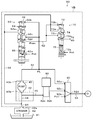
- FIG. 2 is a configuration diagram showing an outline of the configuration of a power transmission device 20.
- FIG. 3 is an explanatory diagram showing an operation table showing the relationship between each gear position of the transmission 30 and the operation states of clutches C1, C2 and brakes B1 to B3.
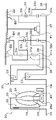
- FIG. 2 is a configuration diagram showing an outline of the configuration around a hydraulic oil storage unit 41, a strainer 42, an oil pump 40, and a hydraulic control device 50.
- FIG. 3 is an explanatory diagram showing a state when the power transmission device 20 is mounted on the automobile 10.
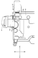
- FIG. 4 is a layout view showing the vicinity of the strainer 42, the oil pump 40, and the electromagnetic pump 80 as viewed from the upper right rear side of the vehicle.
- FIG. 3 is a layout view showing the vicinity of the strainer 42, the oil pump 40, and the electromagnetic pump 80 as viewed from above the vehicle.
- FIG. 4 is a layout view showing the vicinity of the strainer 42, the oil pump 40, and the electromagnetic pump 80 as seen from the rear side of the vehicle.
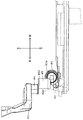
- FIG. 3 is a layout view showing the vicinity of the strainer 42, the oil pump 40, and the electromagnetic pump 80 as viewed from the left side of the vehicle.
- FIG. 1 is a configuration diagram showing an outline of the configuration of an automobile 10 equipped with a power transmission device 20 as an embodiment of the present invention
- FIG. 2 is a configuration diagram showing an outline of the configuration of the power transmission device 20
- FIG. 3 is an explanatory view showing an operation table showing the relationship between the respective speeds of the transmission 30 and the operation states of the clutches C1 and C2 and the brakes B1 to B3.
- FIG. 4 shows the operation oil storage unit 41 and the strainer. 42 is a configuration diagram showing an outline of the configuration around 42, the oil pump 40, and the hydraulic control device 50.
- the automobile 10 of the embodiment is configured as a rear wheel drive vehicle.
- an engine 12 as a prime mover, and an engine electronic control unit (hereinafter referred to as an engine ECU) 14 for controlling the engine 12
- a brake electronic control unit (hereinafter referred to as a brake ECU) 15 for controlling an electronically controlled hydraulic brake unit (not shown), and power for transmitting power from the engine 12 to the drive wheel (rear wheel) DW via the differential gear 100 And a transmission device 20.
- the power transmission device 20 includes hydraulic fluid to the fluid transmission device 23, the stepped transmission 30, the oil pump 40 as a hydraulic pressure generation source of the fluid transmission device 23 and the transmission 30, hydraulic fluid to the fluid transmission device 23 and the transmission 30.
- a hydraulic control device 50 that supplies and discharges the gear, a transmission case 22 that accommodates them, a shift electronic control unit (hereinafter referred to as a shift ECU) 21 that controls the entire device, and the like.
- FIG. 5 is an explanatory diagram showing a state when the power transmission device 20 is mounted on the automobile 10. In FIG.
- an alternate long and short dash line A indicates the horizontal in the power transmission device 20 alone, specifically, the horizontal including the central axes of the input shaft 34 and the output shaft 35, and the horizontal in the automobile 10, specifically, with respect to the ground. Indicates horizontal.
- the power transmission device 20 is mounted on an automobile 10 configured as a rear wheel drive vehicle such that the vehicle rear side is lower than the vehicle front side.
- the engine ECU 14 is input with the accelerator opening from the accelerator pedal position sensor 102 that detects the amount of depression of the accelerator pedal 101 and the vehicle speed from the vehicle speed sensor 108 that detects the vehicle speed.
- the brake ECU 15 receives a brake switch signal from the brake switch 104 that detects depression of the brake pedal 103, a vehicle speed from the vehicle speed sensor 108, and the like.
- the shift ECU 21 is input with the accelerator opening from the accelerator pedal position sensor 102, the shift position SP from the shift position sensor 106 that detects the position of the shift lever 105, the vehicle speed from the vehicle speed sensor 108, and the like.
- the engine ECU 14, the brake ECU 15 and the transmission ECU 21 are connected via a communication port, and exchange various control signals and data with each other.
- the fluid transmission device 23 is configured as a fluid torque converter, and, as shown in FIG. 2, a speed change is made via a pump impeller 24 connected to the crankshaft 16 of the engine 12 via the front cover 18 and a turbine hub.
- the turbine runner 25 connected to the input shaft (input shaft) 34 of the machine 30, the pump impeller 24, and the turbine runner 25 are arranged inside the turbine runner 25 to rectify the flow of hydraulic oil (ATF) from the turbine runner 25 to the pump impeller 24.
- It includes a stator 26, a one-way clutch 26a that limits the rotation direction of the stator 26 to one direction, a damper mechanism (not shown), a lock-up clutch 28, and the like.
- the fluid transmission device 23 may be configured as a fluid coupling that does not have the stator 26.
- the transmission 30 is configured as a six-speed transmission, and each of the first planetary gear mechanism 31, the second planetary gear mechanism 32, the third planetary gear mechanism 33, which is a single pinion planetary gear, and an input A shaft 34, an output shaft (output shaft) 35, two clutches C1, C2, three brakes B1, B2, B3 and a one-way clutch F1 for changing the power transmission path from the input shaft 34 to the output shaft 35; Have.
- the first to third planetary gear mechanisms 31 to 33, the clutches C1 and C2, the brakes B1 to B3, and the one-way clutch F1 are housed inside the transmission case 22.
- the input shaft 34 of the transmission 30 is connected to the crankshaft of the engine via the fluid transmission device 23, and the output shaft 35 is connected to the drive wheels via a differential mechanism (differential gear).
- the first planetary gear mechanism 31 is disposed closest to the engine side (front of the vehicle), that is, closest to the input shaft 34 among the first to third planetary gear mechanisms 31 to 33, and shifts with the second planetary gear mechanism 32 at the rear stage. Configure the gear mechanism.
- the first planetary gear mechanism 31 includes a first sun gear 31s as an external gear, a first ring gear 31r as a fixable element as an internal gear arranged concentrically with the first sun gear 31s, and a first sun gear.
- a first carrier 31c that meshes with 31s and supports the plurality of first pinion gears 31p that mesh with the first ring gear 31r so as to rotate and revolve.
- the first sun gear 31 s of the first planetary gear mechanism 31 is fixed to an annular connecting drum 36 that is connected (spline fitted) to the clutch drum of the clutch C 1 that can rotate integrally with the input shaft 34.
- the second planetary gear mechanism 32 is arranged side by side on the output shaft 35 side (vehicle rear side) of the first planetary gear mechanism 31.
- the second planetary gear mechanism 32 includes a second sun gear 32s as an external gear, a second ring gear 32r as a fixable element as an internal gear arranged concentrically with the second sun gear 32s, and a second sun gear.
- a second carrier 32c that meshes with 32s and supports a plurality of second pinion gears 32p that mesh with the second ring gear 32r so as to rotate and revolve.
- the second sun gear 32 s of the second planetary gear mechanism 32 is fixed to a hollow intermediate shaft 37 that is rotatably disposed between the input shaft 34 and the output shaft 35 with respect to both.
- the second ring gear 32 r of the second planetary gear mechanism 32 is connected to the first carrier 31 c of the first planetary gear mechanism 31.
- the second carrier 32 c of the second planetary gear mechanism 32 is fixed to a sleeve 38 that is coaxially and rotatably supported by the intermediate shaft 37.
- the third planetary gear mechanism 33 is disposed closest to the output shaft 35 (at the rear of the vehicle) among the first to third planetary gear mechanisms 31 to 33, and functions as a reduction gear mechanism.
- the third planetary gear mechanism 33 includes a third sun gear 33s as an external gear, a third ring gear 33r as a fixable element as an internal gear arranged concentrically with the third sun gear 33s, and a third sun gear.
- a third carrier 33c that meshes with 33s and supports the plurality of third pinion gears 33p that mesh with the third ring gear 33r so as to rotate and revolve.
- the third sun gear 33s of the third planetary gear mechanism 33 is fixed to the intermediate shaft 37 and connected to the second sun gear 32s of the second planetary gear mechanism 32, and the third ring gear 33r of the third planetary gear mechanism 33 is the second
- the planetary gear mechanism 32 is connected to the second carrier 32 c, and the third planetary gear mechanism 33 is connected to the output shaft 35.
- the clutch C1 connects the input shaft 34 and the intermediate shaft 37, that is, the second sun gear 32s of the second planetary gear mechanism 32 and the third sun gear 33s of the third planetary gear mechanism 33, and can release the connection therebetween. It is a plate type hydraulic clutch.
- the clutch C2 is a multi-plate hydraulic clutch capable of connecting the input shaft 34 and the sleeve 38, that is, the second carrier 32c of the second planetary gear mechanism 32, and releasing the connection therebetween.
- the one-way clutch F1 restricts reverse rotation while allowing only normal rotation of the second carrier 32c of the second planetary gear mechanism 32 and the third ring gear 33r of the third planetary gear mechanism 33.
- the brake B1 is a multi-plate hydraulic brake that can fix the first ring gear 31r of the first planetary gear mechanism 31 to the transmission case 22 and release the first ring gear 31r from the transmission case 22.
- the brake B2 fixes the first carrier 31c of the first planetary gear mechanism 31 to the transmission case 22, thereby fixing the second ring gear 32r of the second planetary gear mechanism 32 to the transmission case 22, and the first This is a multi-plate hydraulic brake capable of releasing the fixing of the carrier 31c and the second ring gear 32r to the transmission case 22.
- the brake B3 fixes the second carrier 32c of the second planetary gear mechanism 32 and the third ring gear 33r of the third planetary gear mechanism 33 to the transmission case 22, and also transmits the second carrier 32c and the third ring gear 33r. 22 is a multi-plate hydraulic brake that can be released from the fixed state.
- the clutches C1 and C2 and the brakes B1 to B3 operate by receiving and supplying hydraulic oil from the hydraulic control device.
- the transmission 30 provides the first to sixth forward speeds and the first reverse speed by setting the clutches C1 and C2 and the brakes B1 to B3 to the states shown in the operation table of FIG. .
- the oil pump 40 is configured as a gear pump, and includes a pump assembly including a pump body and a pump cover, and an external gear connected to the pump impeller 24 of the fluid transmission device 23 via a hub.
- the oil pump 40 is operated by the power from the engine 12, and the hydraulic oil stored in the hydraulic oil storage section 41 is formed in the strainer 42 and the valve body VB of the hydraulic control device 50 as shown in FIG.
- the oil passage 43, the oil passage 44 formed in the transmission case 22, and the suction port 40a formed in the pump assembly are used for suction and pressure increase, and the pressurized hydraulic oil is supplied via the discharge port 40b formed in the pump assembly.
- the oil is supplied to the oil passage 52 of the hydraulic control device 50.
- the hydraulic control device 50 regulates the hydraulic oil supplied from the oil pump 40 to the oil passage 52 to generate the line pressure PL, and discharges at least a part of the hydraulic oil to the oil passage 68 as the line pressure PL is generated.
- a secondary regulator valve 70 that discharges to 78, a modulator valve (not shown) that generates a constant modulator pressure Pmod using the line pressure PL as a source pressure, and a accelerator pressure or a throttle opening that uses the modulator pressure Pmod as a source pressure.
- a linear solenoid valve SLT (not shown) that drives them by outputting them to the primary regulator valve 60 and the secondary regulator valve 70, an input port for inputting the line pressure PL, an output port for D (drive) position, R (reverse) )
- a position output port is formed to open and close each port in conjunction with the operation of the shift lever 105, and a manual valve MV (not shown) and hydraulic oil output from the D position output port of the manual valve MV are input ports.
- a linear solenoid valve SLC1 (not shown) that adjusts the input hydraulic oil with discharge from the drain port and outputs it from the output port, and a valve body from the oil passage 44 formed in the transmission case 22 Formed in VB
- the electromagnetic pump 80 that sucks the hydraulic oil through the oil passage 45 and discharges the pressurized hydraulic oil, and supplies the hydraulic oil (hydraulic pressure Psl1) from the linear solenoid valve SLC1 to the oil passage 54 of the clutch C1 and electromagnetically.
- a switching valve 90 that switches between a second state to be supplied to.
- the hydraulic oil supplied to the lubricating oil passage 78 can freely rotate the gears of the first to third planetary gear mechanisms 31 to 33, the clutches C1 and C2, the brakes B1 to B3, the differential gear 100, and the rotary shafts. After these are lubricated and supplied to machine parts such as bearings that are supported, the hydraulic oil reservoir 41 is returned again.
- hydraulic systems such as the clutch C2 other than the clutch C1, the brakes B1 to B3, the lock-up clutch 28 of the fluid transmission 23 are omitted because they do not form the core of the present invention.
- the hydraulic system can be configured using a known linear solenoid valve or the like.
- the primary regulator valve 60 is connected to a signal pressure input port 62a that inputs the hydraulic pressure Pslt from the linear solenoid valve SLT as a signal pressure or an oil passage 52 from the oil pump 40, and inputs a line pressure PL as a feedback pressure.
- the amount of oil output from the input port 62c to the oil passage 68 through the output port 62d increases as the spool 64 moves downward in the figure, and the input is performed when the spool 64 moves further downward.
- the hydraulic pressure from the oil pump 40 is reduced to adjust the line pressure PL.
- the spool 64 is biased upward in the figure by the spring force of the spring 66 and the hydraulic pressure acting on the signal pressure input port 62a, and is biased downward in the figure by the line pressure PL acting on the feedback input port 62b. Therefore, the higher the hydraulic pressure Pslt acting on the signal pressure input port 62a, the higher the line pressure PL.
- the hydraulic oil drained from the drain port 62e to the oil passage 56 returns to the oil passage 43.
- the secondary regulator valve 70 is connected to a signal pressure input port 72a for inputting the hydraulic pressure Pslt from the linear solenoid valve SLT as a signal pressure or an oil passage 68 from the primary regulator valve 60, and is used for feedback to input the secondary pressure Psec as a feedback pressure.
- Various ports were formed: an input port 72b, an input port 72c connected to the oil passage 68, an output port 72d connected to the lubricating oil passage 78, and a drain port 72e connected to the oil passage 56 communicating with the oil passage 43.
- the amount of oil output from the input port 72c to the lubricating oil passage 78 through the output port 72d increases as the spool 74 moves downward in the figure, and the spool 74 moves further downward.
- the spool 74 is biased upward in the figure by the spring force of the spring 76 and the hydraulic pressure acting on the signal pressure input port 72a, and is biased downward in the figure by the secondary pressure Psec acting on the feedback input port 72b. Therefore, the secondary pressure Psec increases as the hydraulic pressure Pslt acting on the signal pressure input port 72a increases.
- the hydraulic oil drained from the drain port 62e to the oil passage 56 returns to the oil passage 43.
- the electromagnetic pump 80 includes an electromagnetic part that generates electromagnetic force with energization of the coil, a suction port 82a that sucks hydraulic oil from the oil passage 45, and a discharge port 82b that discharges hydraulic oil.
- a check valve for suction that allows the hydraulic oil to flow in from the suction port 82a while being built in the cylinder and prohibits the flow of hydraulic oil in the opposite direction, and a flow of hydraulic oil to the discharge port 82b that is built in the piston.
- a discharge check valve that permits and prohibits the inflow of hydraulic oil in the opposite direction.
- the hydraulic oil sucked from the suction port 82a is boosted and discharged from the discharge port 82b by reciprocating the piston with intermittent energization of the coil.
- the switching valve 90 includes a signal pressure input port 92a for inputting the line pressure PL as a signal pressure, a first input port 92b connected to the output port of the linear solenoid valve SLC1, and a discharge port 82b of the electromagnetic pump 80.
- the switching valve 90 blocks communication between the second input port 92c and the first output port 92d, and the first input port 92b and the first output port. 92d is communicated.
- the output port of the linear solenoid valve SLC1 communicates with the oil passage 54 of the clutch C1, and the communication between the discharge port 82b of the electromagnetic pump 80 and the oil passage 54 of the clutch C1 is blocked.
- the switching valve 90 blocks communication between the first input port 92b and the first output port 92d, and the second input port 92c and the first output. It communicates with the port 92d. Thereby, the communication between the output port of the linear solenoid valve SLC1 and the oil passage 54 of the clutch C1 is cut off, and the discharge port 82b of the electromagnetic pump 80 and the oil passage 54 of the clutch C1 are communicated.
- the shift lever 105 when the shift lever 105 is traveling in the D (drive) position by the speed change ECU 21, it is based on the accelerator opening from the accelerator pedal position sensor 102 and the vehicle speed from the vehicle speed sensor 108.
- the hydraulic control device 50 (the linear solenoid valve SLT and the linear solenoid valve) is set so that the clutch C1, C2 and the brakes B1 to B3 are engaged and released based on the set target gear position.
- the valve SLC1 and the like are driven and controlled.
- the oil pump 40 is operated by the power from the engine 12, and the line pressure PL is generated by the primary regulator valve 60.
- the switching valve 90 is connected to the output port of the linear solenoid valve SLC1 and the clutch.
- the oil passage 54 of C1 is communicated and the communication between the discharge port 82b of the electromagnetic pump 80 and the oil passage 54 of the clutch C1 is cut off. Therefore, when the clutch C1 is to be engaged according to the target shift speed, the hydraulic pressure Psl1 from the linear solenoid valve SLC1 can be applied to the clutch C1 to engage the clutch C1.
- the shift lever 105 when the shift lever 105 is traveling at the D (drive) position, all of the automatic stop conditions set in advance such as the vehicle speed value 0, the accelerator off, and the brake switch signal on are all satisfied.
- the engine 12 When established, the engine 12 is automatically stopped.
- the engine 12 When the engine 12 is automatically stopped, thereafter, the engine 12 is automatically started when a preset automatic start condition such as a brake switch signal being turned off is satisfied.
- the electromagnetic pump 80 is operated to increase the pressure of the hydraulic oil sucked from the suction port 82a and discharge it from the discharge port 82b (pressure-feed to the switching valve 90 side).
- the line pressure PL decreases due to the oil pump 40 being stopped. Therefore, the switching valve 90 shuts off the communication between the output port of the linear solenoid valve SLC1 and the oil passage 54 of the clutch C1, and also connects the discharge port 82b of the electromagnetic pump 80 and the oil passage 54 of the clutch C1. . Therefore, hydraulic pressure can be applied to the clutch C1 to be engaged at the time of starting by pumping the hydraulic oil by the electromagnetic pump 80.
- the oil pump 40 is operated to supply the line pressure PL. Therefore, the switching valve 90 communicates the output port of the linear solenoid valve SLC1 with the oil passage 54 of the clutch C1, and blocks communication between the discharge port 82b of the electromagnetic pump 80 and the oil passage 54 of the clutch C1. .
- the hydraulic pressure Psl1 from the linear solenoid valve SLC1 to the clutch C1 the vehicle can be started with the clutch C1 completely engaged.
- the hydraulic pressure from the linear solenoid valve SLC1 immediately after the engine 12 is automatically started. Since the clutch C1 can be quickly engaged, the start with the automatic start of the engine 12 can be performed smoothly.
- FIGS. 6 to 9 are layout views showing the strainer 42, the oil pump 40, and the electromagnetic pump 80 viewed from the upper right rear side, upper upper side, rear side, and left side of the vehicle, respectively.
- the oil passage 43 is not shown for ease of viewing.
- the electromagnetic pump 80 is arranged such that a spool (not shown) moves in the left-right direction of the vehicle (the suction port 82a and the discharge port 82b are aligned in the left-right direction of the vehicle). It is attached to VB (not shown in FIGS. 6 to 9).
- the electromagnetic pump 80 is arranged so that the spool moves in the left-right direction of the vehicle because the force (load) due to the acceleration / deceleration acts on the electromagnetic pump 80 during acceleration / deceleration of the vehicle, so that the spool hardly slides in the axial direction. It is for suppressing becoming.
- the electromagnetic pump 80 is attached to the valve body VB because of the discharge port 82b of the electromagnetic pump 80 and the part (such as the switching valve 90) interposed between the electromagnetic pump 80 and the clutch C1 of the hydraulic control device 50. This is to shorten the distance.
- the outlet 42a of the strainer 42, the oil passage 43 formed in the valve body VB, and the oil passage 44 formed in the transmission case 22 are arranged in this order from the vehicle lower side. .
- the outlet 42a of the strainer 42 and the oil passage 44 are positioned such that the distance between them in the vehicle front-rear direction and the vehicle left-right direction is relatively short. This is because the oil pump 40 makes it easy to suck the hydraulic oil stored in the hydraulic oil storage section 41 via the strainer 42, the oil passages 43 and 44, and the suction port 40a.
- the oil passage 44, the oil passage 45 formed in the valve body VB, and the suction port 82a of the electromagnetic pump 80 are arranged in this order from the vehicle upper side. That is, the oil passage 45 is formed toward the suction port 82a so as to extend downward from the horizontal in the power transmission device 20 alone in the entire range from the communication position 45a with the oil passage 44. Further, as described above, the power transmission device 20 is mounted on the automobile 10 configured as a rear wheel drive vehicle so that the vehicle rear side is lower than the vehicle front side. 6 to 9, the suction port 82a of the electromagnetic pump 80 is disposed below the communication position 45a of the oil passage 45 with the oil passage 44 and on the rear side of the vehicle.
- the oil passage 45 extends from the communication position 45a not only in the power transmission device 20 alone but also in the power transmission device 20 mounted on the automobile 10 in the entire range thereof, so that the suction port 82a extends downward. It can be said that it is formed toward
- the suction port 82a of the electromagnetic pump 80 overlaps with the oil passage 45 in the vehicle vertical direction when viewed from the vehicle front-rear direction. As shown in FIGS. 6, 7, and 9, the suction port 82a of the electromagnetic pump 80 overlaps with the outlet 42a of the strainer 42 when viewed from the left-right direction of the vehicle. Accordingly, the distance between the oil passage 44 and the suction port 82a of the electromagnetic pump 80 in the vehicle front-rear direction and the vehicle left-right direction can be shortened. In particular, in the embodiment, the distance in the vehicle left-right direction between the oil passage 44 and the suction port 82a of the electromagnetic pump 80 can be further shortened (substantially zero).
- the engine 12 is automatically stopped, and the electromagnetic pump 80 is driven to apply hydraulic pressure to the clutch C1 in preparation for the subsequent start.
- the air flows above the oil passages 43, 44 (particularly the oil passage 44). May accumulate.
- air air pool may reach the oil passage 45.
- the air reaching the upper portion of the oil passage 45 reaches the suction port 82 a of the electromagnetic pump 80 with a relatively small inclination in the vehicle front-rear direction and the vehicle left-right direction of the automobile 10.
- the electromagnetic pump 80 may inhale air.
- the electromagnetic pump 80 sucks air, the hydraulic pressure applied to the clutch C1 from the electromagnetic pump 80 decreases (insufficient), and then the engine 12 is automatically started and the clutch C1 is engaged by the hydraulic pressure from the linear solenoid valve SLC1. In addition, it takes time to engage the clutch C1, and the startability of the vehicle may be reduced.
- the electromagnetic pump 80 unlike when using an electric pump, it is difficult to discharge the air when it is sucked.
- such an electric pump 80 is often used in a relatively small size, and the influence of a decrease in the discharge pressure when air is sucked in is likely to appear. Due to these factors, it is required to further suppress the electromagnetic pump 80 from sucking air.
- the suction passage 82a of the electromagnetic pump 80 extends so that the oil passage 45 extends downward from the horizontal in the power transmission device 20 alone or the vehicle 10 from the communication position 45a with the oil passage 44 in the entire range. Further, the distance between the oil passage 44 and the suction port 82a of the electromagnetic pump 80 in the vehicle front-rear direction and the vehicle left-right direction is shortened. Thus, it is possible to prevent the air (air reservoir) accumulated in the oil passage 44 from reaching the oil passage 45 and the suction port 82a of the electromagnetic pump 80 unless the automobile 10 is largely inclined in the vehicle front-rear direction or the vehicle left-right direction. It is possible to suppress the electromagnetic pump 80 from sucking air.
- the distance between the oil passage 44 and the suction port 82a of the electromagnetic pump 80 in the left-right direction of the vehicle is made shorter (substantially zero). Has a greater effect.
- the electromagnetic pump 80 by suppressing the electromagnetic pump 80 from sucking air, it is possible to suppress a decrease in the hydraulic pressure applied from the electromagnetic pump 80 to the clutch C1.
- the engine 12 is automatically started and the clutch C1 is engaged by the hydraulic pressure from the linear solenoid valve SLC1, it is possible to suppress the time required for the engagement of the clutch C1 from being increased. Can be suppressed.
- the oil passage 45 that communicates the oil passage 44 and the electromagnetic port 80 is located in the entire range from the communication position 45a with the oil passage 44 in the power transmission device 20 alone or the automobile 10. It is formed toward the suction port 82a of the electromagnetic pump 80 so as to extend downward from the horizontal. Further, the suction port 82a of the electromagnetic pump 80 is formed on the transmission case 22 below the vehicle from the oil passage 44 formed between the outlet 42a of the strainer 42 and the oil pump 40 when viewed from the front-rear direction of the vehicle. And overlaps the oil passage 44 in the vehicle vertical direction. The suction port 82a overlaps the outlet 42a of the strainer 42 when viewed from the left-right direction of the vehicle.
- the distance between the oil passage 44 and the suction port 82a of the electromagnetic pump 80 in the vehicle front-rear direction and the vehicle left-right direction can be shortened.
- the air (air reservoir) accumulated in the oil passage 44 is not removed from the oil passage 45 or the electromagnetic pump unless the automobile 10 is largely inclined in the vehicle front-rear direction or the vehicle left-right direction.
- the hydraulic pressure needs to be applied from the electromagnetic pump 80 to the clutch C1
- the suction port 82a of the electromagnetic pump 80 overlaps with the outlet 42a of the strainer 42 when viewed from the left-right direction of the vehicle as shown in FIG.
- the oil passage 44 may overlap the vertical direction of the vehicle. In this way, the distance in the vehicle front-rear direction between the oil passage 44 and the suction port 82a of the electromagnetic pump 80 can be further shortened, and a greater effect can be obtained with respect to the inclination of the automobile 10 in the vehicle front-rear direction.
- the suction port 82a of the electromagnetic pump 80 may be disposed so as to overlap the outlet 42a of the strainer 42 and the oil passage 44 in the vehicle vertical direction when viewed from the vehicle left-right direction. . In this case, the suction port 82a of the electromagnetic pump 80 may not overlap with the oil passage 44 in the vehicle vertical direction when viewed from the vehicle front-rear direction.
- the suction port 82a of the electromagnetic pump 80 is located on the vehicle lower side from the oil passage 44 and overlaps the oil passage 44 in the vehicle vertical direction when viewed from the vehicle front-rear direction.
- the oil passage 45 overlaps with the outlet 42a of the strainer 42.
- the oil passage 45 extends downward from the horizontal in the power transmission device 20 alone and the vehicle 10 in the entire range from the communication position 45a with the oil passage 44.
- the suction port 82a of the electromagnetic pump 80 does not overlap the oil passage 44 in the vehicle vertical direction when viewed from the vehicle front-rear direction, and does not overlap with the vehicle left-right direction.
- the distance between the oil passage 44 and the suction port 82a of the electromagnetic pump 80 in the vehicle front-rear direction and the vehicle left-right direction becomes longer.
- the oil passage 45 is connected to the oil passage 44 from the communication position 45a alone, When air accumulates in the upper portion of the oil passage 44 as compared with the vehicle 10 that is formed toward the suction port 82a so as to extend horizontally or upward, the air (air reservoir) becomes the oil passage 45.
- the electromagnetic pump 80 can be prevented from reaching the suction port 82a, and the electromagnetic pump 80 can be prevented from sucking air.
- the power transmission device 20 of the embodiment includes the electromagnetic pump 80 that operates by electromagnetic force
- the power transmission device 20 may include an electric pump that operates by power from an electric motor.
- the six-speed transmission 30 is provided, but is not limited to the six-speed transmission, and is not limited to the six-speed transmission. Any number of transmissions such as a formula may be provided.
- the engine 12 is provided as a prime mover, but a motor other than the engine may be provided.
- the power transmission device 20 is mounted on the automobile 10 configured as a rear wheel drive vehicle, but may be mounted on a front wheel drive vehicle.
- the transmission 30 corresponds to a “transmission”
- the transmission case 22 corresponds to a “case”
- the hydraulic control device 50 corresponds to a “hydraulic control device”
- the oil pump 40 corresponds to a “first pump”.
- the electromagnetic pump 80 corresponds to the “electromagnetic pump”
- the oil passages 43 and 44 correspond to the “first oil passage”
- the oil passage 45 corresponds to the “second oil passage”.
- the present invention can be used in the power transmission device manufacturing industry.
Landscapes
- Engineering & Computer Science (AREA)
- General Engineering & Computer Science (AREA)
- Mechanical Engineering (AREA)
- Control Of Transmission Device (AREA)
- General Details Of Gearings (AREA)
Abstract
Description
車両に搭載され、原動機からの動力を車軸に伝達するための複数の係合要素を有する変速機と、前記変速機を収容するケースと、前記複数の係合要素への油圧を制御する油圧制御装置と、を備える動力伝達装置であって、
前記作動油を貯留する作動油貯留部と、
前記原動機からの動力により作動し、前記作動油貯留部の作動油を吸入すると共に昇圧した作動油を前記油圧制御装置に供給する第1ポンプと、
電力の供給を受けてピストンが往復動する往復動ポンプとして構成され、前記作動油貯留部の作動油を吸入すると共に昇圧した作動油を前記複数の係合要素のうち発進時に係合される発進時係合要素に供給する第2ポンプと、
前記作動油貯留部と前記第1ポンプとを連通する第1油路と、
前記第1油路と前記第2ポンプとを連通する第2油路と、
を備え、
前記第2油路は、前記第1油路との連通位置からその全範囲において水平より下向きに延びるように前記第2ポンプの吸入口に向けて形成されている、
ことを要旨とする。
Claims (7)
- 車両に搭載され、原動機からの動力を車軸に伝達するための複数の係合要素を有する変速機と、前記変速機を収容するケースと、前記複数の係合要素への油圧を制御する油圧制御装置と、を備える動力伝達装置であって、
前記作動油を貯留する作動油貯留部と、
前記原動機からの動力により作動し、前記作動油貯留部の作動油を吸入すると共に昇圧した作動油を前記油圧制御装置に供給する第1ポンプと、
電力の供給を受けてピストンが往復動する往復動ポンプとして構成され、前記作動油貯留部の作動油を吸入すると共に昇圧した作動油を前記複数の係合要素のうち発進時に係合される発進時係合要素に供給する第2ポンプと、
前記作動油貯留部と前記第1ポンプとを連通する第1油路と、
前記第1油路と前記第2ポンプとを連通する第2油路と、
を備え、
前記第2油路は、前記第1油路との連通位置からその全範囲において水平より下向きに延びるように前記第2ポンプの吸入口に向けて形成されている、
動力伝達装置。 - 請求項1記載の動力伝達装置であって、
前記第1油路は、前記油圧制御装置のバルブボディに形成されて前記作動油貯留部にストレーナを介して連通するボディ側油路と、前記ケースに形成されて前記ボディ側油路と前記第1ポンプとを連通するケース側油路とからなり、
前記第2油路は、前記バルブボディに形成されて前記ケース側油路と前記第2ポンプとを連通しており、
前記ケース側油路,前記第2油路,前記第2ポンプは、車両上側からこの順に並んでおり、
前記第2ポンプは、前記吸入口が車両前後方向と車両左右方向とのうち少なくとも一方から見て前記ケース側油路と車両上下方向で重なるよう配置されている、
動力伝達装置。 - 請求項2記載の動力伝達装置であって、
前記車両は、後輪駆動車両であり、
前記第2ポンプは、前記吸入口が車両前後方向から見て前記ケース側油路と車両上下方向で重なるように配置されている、
動力伝達装置。 - 請求項3記載の動力伝達装置であって、
前記第2ポンプは、前記吸入口が車両左右方向から見て前記ケース側油路と車両上下方向で重なるおよび/または前記ストレーナの出口と重なるように配置されている、
動力伝達装置。 - 請求項1または2記載の動力伝達装置であって、
前記動力伝達装置は、後輪駆動車両に、車両後側が車両前側より低くなるように搭載され、
前記第2ポンプは、前記吸入口が前記連通位置より下側且つ車両後側となるように配置されている、
動力伝達装置。 - 請求項1ないし5のいずれか1つの請求項に記載の動力伝達装置であって、
前記第2ポンプは、電磁力により油圧を発生させる電磁ポンプとして構成され、前記バルブボディに取り付けられている、
動力伝達装置。 - 請求項1ないし6のいずれか1つの請求項に記載の動力伝達装置であって、
前記発進時係合要素を係合すべき場合に、前記第1ポンプが作動しているときには該第1ポンプから吐出されて調圧された作動油が前記発進時係合要素に供給される第1状態を形成し、前記第1ポンプが作動していないときには前記第2ポンプから吐出された作動油
が前記発進時係合要素に供給される第2状態を形成する切替バルブを備える、
動力伝達装置。
Priority Applications (4)
| Application Number | Priority Date | Filing Date | Title |
|---|---|---|---|
| JP2015539252A JP6041057B2 (ja) | 2013-09-25 | 2014-09-24 | 動力伝達装置 |
| CN201480046330.2A CN105492802B (zh) | 2013-09-25 | 2014-09-24 | 动力传递装置 |
| US14/913,060 US9777830B2 (en) | 2013-09-25 | 2014-09-24 | Power transmission device |
| DE112014003359.6T DE112014003359T5 (de) | 2013-09-25 | 2014-09-24 | Kraftübertragungsvorrichtung |
Applications Claiming Priority (2)
| Application Number | Priority Date | Filing Date | Title |
|---|---|---|---|
| JP2013-198548 | 2013-09-25 | ||
| JP2013198548 | 2013-09-25 |
Publications (1)
| Publication Number | Publication Date |
|---|---|
| WO2015046233A1 true WO2015046233A1 (ja) | 2015-04-02 |
Family
ID=52743368
Family Applications (1)
| Application Number | Title | Priority Date | Filing Date |
|---|---|---|---|
| PCT/JP2014/075254 Ceased WO2015046233A1 (ja) | 2013-09-25 | 2014-09-24 | 動力伝達装置 |
Country Status (5)
| Country | Link |
|---|---|
| US (1) | US9777830B2 (ja) |
| JP (1) | JP6041057B2 (ja) |
| CN (1) | CN105492802B (ja) |
| DE (1) | DE112014003359T5 (ja) |
| WO (1) | WO2015046233A1 (ja) |
Cited By (3)
| Publication number | Priority date | Publication date | Assignee | Title |
|---|---|---|---|---|
| JP2015206298A (ja) * | 2014-04-21 | 2015-11-19 | 株式会社 神崎高級工機製作所 | 二連ポンプ構造 |
| EP3434900A4 (en) * | 2016-03-22 | 2019-04-03 | Jatco Ltd. | VENTILATION STRUCTURE OF AN AUTOMATIC TRANSMISSION OIL PUMP AND METHOD OF ASSEMBLING A VENTILATION STRUCTURE |
| JP2019219008A (ja) * | 2018-06-20 | 2019-12-26 | 本田技研工業株式会社 | 油圧回路 |
Families Citing this family (2)
| Publication number | Priority date | Publication date | Assignee | Title |
|---|---|---|---|---|
| US11009139B2 (en) * | 2017-05-19 | 2021-05-18 | Aisin Aw Co., Ltd. | Relief valve |
| CN108426025B (zh) * | 2018-03-12 | 2019-12-03 | 安徽江淮汽车集团股份有限公司 | 双离合器自动变速器排气控制方法及控制系统 |
Citations (6)
| Publication number | Priority date | Publication date | Assignee | Title |
|---|---|---|---|---|
| JPH03134368A (ja) * | 1989-10-18 | 1991-06-07 | Nissan Motor Co Ltd | 変速機の油圧制御装置 |
| JP2004332886A (ja) * | 2003-05-12 | 2004-11-25 | Mazda Motor Corp | 自動変速機のオイル吸入装置 |
| JP2008267498A (ja) * | 2007-04-20 | 2008-11-06 | Toyota Motor Corp | 車両用オイル供給装置 |
| JP2010164178A (ja) * | 2009-01-19 | 2010-07-29 | Aisin Aw Co Ltd | 動力伝達装置およびこれを搭載する車両 |
| JP2012122560A (ja) * | 2010-12-09 | 2012-06-28 | Aisin Aw Co Ltd | 動力伝達装置 |
| US20120247902A1 (en) * | 2011-04-04 | 2012-10-04 | GM Global Technology Operations LLC | Electro-hydraulic control system for an automatic transmission |
Family Cites Families (5)
| Publication number | Priority date | Publication date | Assignee | Title |
|---|---|---|---|---|
| JP5233852B2 (ja) * | 2009-06-11 | 2013-07-10 | アイシン・エィ・ダブリュ株式会社 | 電磁弁装置 |
| JP5083303B2 (ja) * | 2009-12-15 | 2012-11-28 | アイシン・エィ・ダブリュ株式会社 | ポンプ装置および動力伝達装置並びに車両 |
| JP5549565B2 (ja) * | 2010-12-03 | 2014-07-16 | アイシン・エィ・ダブリュ株式会社 | 動力伝達装置 |
| EP2677128B1 (en) * | 2011-02-15 | 2017-04-26 | Toyota Jidosha Kabushiki Kaisha | Control device for vehicle oil supply device |
| JP5440531B2 (ja) * | 2011-03-18 | 2014-03-12 | アイシン・エィ・ダブリュ株式会社 | 自動変速機の流体圧制御装置 |
-
2014
- 2014-09-24 JP JP2015539252A patent/JP6041057B2/ja not_active Expired - Fee Related
- 2014-09-24 US US14/913,060 patent/US9777830B2/en active Active
- 2014-09-24 DE DE112014003359.6T patent/DE112014003359T5/de not_active Withdrawn
- 2014-09-24 WO PCT/JP2014/075254 patent/WO2015046233A1/ja not_active Ceased
- 2014-09-24 CN CN201480046330.2A patent/CN105492802B/zh active Active
Patent Citations (6)
| Publication number | Priority date | Publication date | Assignee | Title |
|---|---|---|---|---|
| JPH03134368A (ja) * | 1989-10-18 | 1991-06-07 | Nissan Motor Co Ltd | 変速機の油圧制御装置 |
| JP2004332886A (ja) * | 2003-05-12 | 2004-11-25 | Mazda Motor Corp | 自動変速機のオイル吸入装置 |
| JP2008267498A (ja) * | 2007-04-20 | 2008-11-06 | Toyota Motor Corp | 車両用オイル供給装置 |
| JP2010164178A (ja) * | 2009-01-19 | 2010-07-29 | Aisin Aw Co Ltd | 動力伝達装置およびこれを搭載する車両 |
| JP2012122560A (ja) * | 2010-12-09 | 2012-06-28 | Aisin Aw Co Ltd | 動力伝達装置 |
| US20120247902A1 (en) * | 2011-04-04 | 2012-10-04 | GM Global Technology Operations LLC | Electro-hydraulic control system for an automatic transmission |
Cited By (3)
| Publication number | Priority date | Publication date | Assignee | Title |
|---|---|---|---|---|
| JP2015206298A (ja) * | 2014-04-21 | 2015-11-19 | 株式会社 神崎高級工機製作所 | 二連ポンプ構造 |
| EP3434900A4 (en) * | 2016-03-22 | 2019-04-03 | Jatco Ltd. | VENTILATION STRUCTURE OF AN AUTOMATIC TRANSMISSION OIL PUMP AND METHOD OF ASSEMBLING A VENTILATION STRUCTURE |
| JP2019219008A (ja) * | 2018-06-20 | 2019-12-26 | 本田技研工業株式会社 | 油圧回路 |
Also Published As
| Publication number | Publication date |
|---|---|
| DE112014003359T5 (de) | 2016-04-07 |
| JPWO2015046233A1 (ja) | 2017-03-09 |
| CN105492802A (zh) | 2016-04-13 |
| US9777830B2 (en) | 2017-10-03 |
| CN105492802B (zh) | 2017-02-15 |
| US20160201796A1 (en) | 2016-07-14 |
| JP6041057B2 (ja) | 2016-12-07 |
Similar Documents
| Publication | Publication Date | Title |
|---|---|---|
| JP5177123B2 (ja) | 動力伝達装置 | |
| JP5195449B2 (ja) | 動力伝達装置およびこれを搭載する車両 | |
| JP2015054578A (ja) | 作業車両の走行伝動装置 | |
| JP5195471B2 (ja) | 動力伝達装置およびこれを搭載する車両 | |
| JP6041057B2 (ja) | 動力伝達装置 | |
| JP5418486B2 (ja) | 動力伝達装置 | |
| CN105697758B (zh) | 自动变速器液压控制系统中的电子变速器范围选择子系统 | |
| JP5093169B2 (ja) | 電磁弁装置 | |
| JP2011127633A (ja) | ポンプ装置および動力伝達装置並びに車両 | |
| JP2010169249A (ja) | 動力伝達装置およびこれを搭載する車両 | |
| JP6070861B2 (ja) | 動力伝達装置 | |
| CN105579745B (zh) | 油压控制装置 | |
| JP5233693B2 (ja) | 動力伝達装置およびこれを搭載する車両 | |
| JP4714926B2 (ja) | ポンプユニット | |
| JP5375714B2 (ja) | 自動変速機 | |
| KR102784461B1 (ko) | 유압 기어 박스 액츄에이터 | |
| US20210018088A1 (en) | Oil supply system for vehicle | |
| JP2015017624A (ja) | 車両用潤滑装置 | |
| JP2010180960A (ja) | 動力伝達装置およびこれを搭載する車両 | |
| JP2011214617A (ja) | 油圧制御装置 |
Legal Events
| Date | Code | Title | Description |
|---|---|---|---|
| WWE | Wipo information: entry into national phase |
Ref document number: 201480046330.2 Country of ref document: CN |
|
| 121 | Ep: the epo has been informed by wipo that ep was designated in this application |
Ref document number: 14846829 Country of ref document: EP Kind code of ref document: A1 |
|
| ENP | Entry into the national phase |
Ref document number: 2015539252 Country of ref document: JP Kind code of ref document: A |
|
| WWE | Wipo information: entry into national phase |
Ref document number: 112014003359 Country of ref document: DE |
|
| WWE | Wipo information: entry into national phase |
Ref document number: 14913060 Country of ref document: US |
|
| 122 | Ep: pct application non-entry in european phase |
Ref document number: 14846829 Country of ref document: EP Kind code of ref document: A1 |