WO2015046210A1 - 自転車用駆動装置 - Google Patents
自転車用駆動装置 Download PDFInfo
- Publication number
- WO2015046210A1 WO2015046210A1 PCT/JP2014/075208 JP2014075208W WO2015046210A1 WO 2015046210 A1 WO2015046210 A1 WO 2015046210A1 JP 2014075208 W JP2014075208 W JP 2014075208W WO 2015046210 A1 WO2015046210 A1 WO 2015046210A1
- Authority
- WO
- WIPO (PCT)
- Prior art keywords
- shaft
- pedal
- crank
- crank arm
- gear
- Prior art date
- Legal status (The legal status is an assumption and is not a legal conclusion. Google has not performed a legal analysis and makes no representation as to the accuracy of the status listed.)
- Ceased
Links
Images


Classifications
-
- B—PERFORMING OPERATIONS; TRANSPORTING
- B62—LAND VEHICLES FOR TRAVELLING OTHERWISE THAN ON RAILS
- B62M—RIDER PROPULSION OF WHEELED VEHICLES OR SLEDGES; POWERED PROPULSION OF SLEDGES OR SINGLE-TRACK CYCLES; TRANSMISSIONS SPECIALLY ADAPTED FOR SUCH VEHICLES
- B62M1/00—Rider propulsion of wheeled vehicles
- B62M1/10—Rider propulsion of wheeled vehicles involving devices which enable the mechanical storing and releasing of energy occasionally, e.g. arrangement of flywheels
-
- B—PERFORMING OPERATIONS; TRANSPORTING
- B62—LAND VEHICLES FOR TRAVELLING OTHERWISE THAN ON RAILS
- B62M—RIDER PROPULSION OF WHEELED VEHICLES OR SLEDGES; POWERED PROPULSION OF SLEDGES OR SINGLE-TRACK CYCLES; TRANSMISSIONS SPECIALLY ADAPTED FOR SUCH VEHICLES
- B62M3/00—Construction of cranks operated by hand or foot
- B62M3/02—Construction of cranks operated by hand or foot of adjustable length
- B62M3/04—Construction of cranks operated by hand or foot of adjustable length automatically adjusting
-
- B—PERFORMING OPERATIONS; TRANSPORTING
- B62—LAND VEHICLES FOR TRAVELLING OTHERWISE THAN ON RAILS
- B62M—RIDER PROPULSION OF WHEELED VEHICLES OR SLEDGES; POWERED PROPULSION OF SLEDGES OR SINGLE-TRACK CYCLES; TRANSMISSIONS SPECIALLY ADAPTED FOR SUCH VEHICLES
- B62M3/00—Construction of cranks operated by hand or foot
- B62M2003/006—Crank arrangements to overcome dead points
Definitions
- the present invention relates to a bicycle drive device that smoothly converts a linear motion force in one direction input to a pedal of a bicycle into a rotational motion of a drive system based on a pedal and a gear.
- the above-mentioned conventional one is provided with a disc-shaped eccentric weight on either one of the crank arms, so that when the crank arm starts rotating, the position of the pedal provided at the tip of the crank arm is changed to the pedal rotation motion.
- the present invention relates to a bicycle drive device mainly composed of a crank arm and a pedal that are set so as to be slightly stepped on from the top dead center position.
- the rotational kinetic energy of the pedal in the state where one pedal has started the rotational motion and A balance weight that generates an equivalent rotational motion energy is provided on the side of the crank arm on which the pedal is mounted and on the side facing the pedal, thereby smoothly performing the rotational motion of the pedal.
- a balance weight that generates an equivalent rotational motion energy is provided on the side of the crank arm on which the pedal is mounted and on the side facing the pedal, thereby smoothly performing the rotational motion of the pedal.
- a shaft that is provided in a part of the body frame and is provided so as to be capable of rotating, and both ends of the shaft.
- Two crank arms provided at right angles with respect to the shaft and symmetrically with respect to the center of the shaft, and provided at the tip of each crank arm.
- a gear to be attached to one end of the shaft and to which the chain is attached, and a surface formed by the rotational movement of the crank arm Provided to generate kinetic energy equivalent to the kinetic energy formed by the rotational movement of the crank arm and pedal.
- the balance weight is mounted so that the mounting position of these balance weights can be appropriately adjusted within an arc having a predetermined radius with respect to the shaft center of the shaft. .
- a shaft provided on a part of the body frame and provided so as to be capable of rotational movement
- Two crank arms provided at both ends so as to be perpendicular to the shaft and to form a 180 ° symmetrical shape with respect to the center of the shaft, and provided at the tip of each crank arm Provided on one end side of the shaft and a gear to which the chain is attached, and provided on one surface side of the gear, and for rotational movement of the crank arm and the pedal.
- adopting a configuration in which the mounting position of the balance weight can be appropriately adjusted within an arc having a predetermined radius with respect to the shaft center of the shaft. did.
- the balance weight is set to a longitudinal center line of one crank arm.
- the two-piece structure is formed so as to form a symmetrical shape, and each piece is either one of the plane or the gear and is on one of the surfaces.
- a configuration is adopted in which the mounting position can be adjusted in the circumferential direction.
- the bicycle drive device is provided on a part of the body frame and is provided so as to be capable of rotational movement, and the shaft.
- Two crank arms provided at both ends so as to be perpendicular to the shaft and symmetrical with respect to the center of the shaft at 180 °, and tip portions of the crank arms
- a pedal a disc-like gear provided on one end of the shaft and to which the chain is attached, and one surface of a disc-like member formed so as to be parallel to the gear
- the bicycle drive device is provided on a part of the body frame and is provided so as to be capable of rotational movement, and the shaft.
- Two crank arms provided at both ends so as to be perpendicular to the shaft and symmetrical with respect to the center of the shaft at 180 °, and tip portions of the crank arms
- a pedal provided on one end of the shaft, a gear to which a chain is attached, and a surface formed on one end of the shaft,
- a first balance weight provided on an extension of the longitudinal center line of one of the crank arms, and an end on the other side of the shaft.
- the crank arm is provided on the crankshaft side with respect to the bicycle drive device according to any one of the first to fifth aspects.
- the arm and a second arm provided on the pedal side, and the length between the center of the crankshaft formed by these arms and the center of the pedal mounting portion can be adjusted as appropriate. It was decided to adopt the configuration as described above.
- the balance of the rotational kinetic energy amounts mainly of one crank arm and the pedal is maintained. That is, in the present invention, the balance weight is provided on the longitudinal axis of one crank arm, and the value of the rotational kinetic energy formed by the balance weight and the rotational movement of the crank arm and pedal, mainly the pedal. It is possible to maintain the value of the kinetic energy formed by the vehicle in an equivalent state, and thereby, it is possible to maintain a smooth rotational motion operation when the passenger depresses the pedal. .
- the mounting position of the balance weight can be finely adjusted as appropriate on the circumferential surface of the gear or the circumferential surface of the mounting member.
- the pedal is mainly used as a pedal.
- the overall balance can be achieved by finely adjusting the mounting state of the balance weight with respect to fluctuations in rotational kinetic energy caused by fluctuations in the mass of the crank arm. As a result, the rotational movement operation of the pedal can be held smoothly.
- balance weights are provided at both ends of the shaft.
- the whole crank arm has a two-part structure, and these two arm portions are connected by a connecting bolt.
- the connecting bolt By appropriately relaxing or tightening the connecting bolt, the entire length of the crank arm can be changed (changed) in accordance with the situation at that time.
- the length of the crank arm can be adjusted to an appropriate value although it is within a certain range.
- FIG. 5 is a view showing a state where the mounting position of each plate is finely adjusted in the case where two balance plates are provided on the gear side.
- the basic configuration of the present embodiment is that the centrifugal force M, which is the kinetic energy formed by the rotational movement of the pedal, and the total value of the centrifugal force formed by the rotational movement of each balance weight ( Vector)
- the value of F is set to an equivalent state.
- a shaft assembly (shaft) 3 provided at a part of the body frame, for example, at a lower portion and provided so as to be rotatable, Two shafts provided at both ends of the shaft 3 so as to form a 180 ° symmetrical shape with respect to the shaft 3 at right angles and with the center O 1 O 1 (see FIG.
- a balance plate 1 (see FIG. 2) provided on a surface formed so as to be parallel to the surface formed by the weight 2 or the crank arm 6 rotating, and having a predetermined mass; It is based on what consists of.
- the balance weight can be broadly divided into two types.
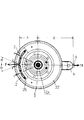
- One is composed of a two-piece structure, for example, as shown in FIG. That is, the respective chip-like balance weights 2 and 2 are attached to the circumferential surface of the disk plate 22 provided so as to be parallel to the flywheel 5 via the attachment bolts 25 and the like. Then, the disc plate 22 to which such chip-shaped balance weights 2 and 2 are attached is connected to the center bolt 36 (see FIG. 5) on one end side of the shaft 3 together with the flywheel 5 and the like via a predetermined attachment member 88. 2)). Further, a crank arm 6 is attached to one end portion side of the shaft 3 to which the flywheel 5 and the disk plate 22 are attached, and a pedal 9 is attached to the end portion side of the crank arm 6. It is something like that.
- each of the chip-like balance weights 2 and 2 is attached on the circumferential surface of the disk plate 22 via a mounting bolt 25 in a concentric manner as shown in FIG. 1 or FIG. It is something like that.
- the chip-like balance weights 2 and 2 may be mounted directly on one surface side of the gear 8, for example, as shown in FIG.
- Each of the chip-like balance weights 2 and 2 in these cases has an attachment state in which the value of an arbitrary angle ( ⁇ ) can be appropriately set as shown in FIG. 3, for example. It is.
- the resultant value (vector value) F of the centrifugal force formed by the balance weights 2 and 2 is mainly determined by the kinetic energy generated by the rotational movement of the pedal 9. It is made to balance in the state equivalent to the value of the centrifugal force M formed.
- the mounting state of the balance weights 2 and 2 is finely adjusted so that the mounting angles ⁇ 1 and ⁇ 2 are set. It is what you are doing.
- the value of ⁇ is changed to ⁇ 1 or ⁇ 2 in the case where the value of the centrifugal force M 1 mainly including the pedal 9 is changed due to a specification change or the like.
- the respective chip-like balance weights 2 and 2 forming the balance weight are directly attached to any one side of the gear 8. This is, for example, as shown in FIG. 5 (A) or (B), and is attached to the gear 8 via a mounting bolt 25.
- the disk plate 22 is omitted, so that the mass of the entire drive device can be reduced and the manufacturing cost can be reduced.
- fine adjustment of the mounting position of the chip-like balance weight 2 is performed by appropriately adjusting the value of ⁇ as shown in FIGS. 5 (A) and 5 (B).
- the adjustment of the attachment of the balance weights 2 and 2 is performed by loosening or tightening the attachment bolts 25 as appropriate.
- FIG. 2 Another example of the balance weight is shown in FIG. This is formed on the basis of the balance plate 1.
- the plate-like form is used, and the plate-like form having a mass portion 11 formed at a position decentered by a predetermined amount with respect to the center line O 1 O 1 .
- the balance plate 1 is shown as having two plates, but the number of the balance plates 1 is not particularly limited, and may be one. Depending on the case, it may be three or more. In short, it is sufficient if a predetermined amount of balance weight is formed. And the balance plate 1 which consists of such a structure is attached to the other end part side of the said shaft 3 with the gear 8 etc.
- crank arm 6 is attached to the end portion side of the shaft 3 in a state where the gear 8, the balance plate 1 and the like are attached.
- the crank arm 6 is attached to the crank arm 6 shown in FIG. 1 so as to form a 180 ° symmetric shape in a plane perpendicular to the center line O 1 O 1 of the shaft 3. It is what.
- the pedal 9 is attached to the front-end
- the basic configuration of the balance plates 1 and 1 having such a configuration is that, for example, as shown in FIG. 6, the position of the center of gravity is located on the extension line including the center point O 1 in the longitudinal center line of one crank arm 6. Is what comes to come.
- the positions of the respective mass portions 11 and 11 are set so that the opening angle ( ⁇ between each other, as shown in FIGS. 6 (A) and 6 (B), for example. 1 , ⁇ 2 ) is set (adjusted). Specifically, first, the balance plates 1 and 1 are fixed, and the tightening force of the mounting bolts 25 provided in the notch grooves 15 provided in the balance plates 1 and 1 is relaxed.
- the chip-like balance weight 2 is provided on the circumferential surface of the disk plate 22 and on the extension line (including O 1 ) of the longitudinal center line of the crank arm 6. It is what. Specifically, as shown in FIGS. 7A and 7B, the chip-like balance weight 2 is attached to the circumferential surface of the disk plate 22 through the lock bolt 29 at the slit 28. It is what has become. Since the slit 28 has a long hole shape, the tip-shaped balance weight 2 itself is moved from the state shown in FIG. It can be changed to the state.
- a tip-like balance weight 2 is provided on one end side of the shaft 3 and a balance is provided on the other end side of the shaft 3.
- a composite system in which a balance weight of the plate 1 system is provided will be described with reference to FIG.
- a disk plate 22 having a chip-like balance weight 2 on its circumferential surface is attached to one end side of the shaft 3 via an attachment member 88 and a center bolt 36.
- the flywheel 5 is attached to the outside of such a disc plate 22.
- one crank arm 6 is provided on one end side of the shaft 3, and a pedal 9 is provided at the end of the crank arm 6.
- the gear 8 is attached to the other end side of the shaft 3 via an attachment member 88 and a center bolt 36.
- the balance plate 1 is attached to the outside of the gear 8.
- the balance plate 1 is further attached to the other end side of the shaft 3.
- the other crank arm 6 is attached.
- a pedal 9 is attached to the end portion of the crank arm 6 so that the entire driving device is formed.
- the tip-shaped balance weight 2 is provided on the one end side of the shaft 3 with the disc plate 22 in the center, and the other end side. Is provided with another balance weight made of the balance plate 1 so that an equilibrium state can be formed between the left and right balance weights with reference to the center line in the longitudinal direction of the bicycle body. Become. As a result, during the operation of the present drive device, that is, during the rotational motion of the flywheel 5, the disc plate 22, the gear 8, and the balance plate 1 around the shaft 3, a smooth rotational motion is formed. As a result, the occupant can maintain a smooth motion around the leg portion, and can perform a comfortable bicycle run.
- the crank arm has a two-part structure, and the length of all crank arms is changed from L to L ′.
- the first arm 61 provided so as to be rotatable about the shaft center point O 1 of the crankshaft, and an extension line of the first arm 61. be those provided is for the second arm 62 the pedal 9 is at its distal end is mounted so as to freely rotate around the attachment point O 9, basically in that it consists of.
- the shaft portion of the connecting bolt 7 is disposed around the connecting portion of the second arm 62 to the first arm 61 as shown in FIGS. 9A and 9B, for example.
- the connection between the first arm 61 and the second arm 62 is relaxed in an elongated hole 66 formed in the second arm 62 by relaxing the fastening state of the connecting bolt 7.
- the connecting bolt 7 By tightening the connecting bolt 7 again, the value of L formed by the first arm 61 and the second arm 62 can be adjusted to an appropriate value, for example, L ′.
- the distance (L) from the crankshaft center (O 1 ) to the attachment point (O 9 ) of the pedal 9 is appropriately set (adjusted) according to the situation at that time. ) Will be able to.
Landscapes
- Engineering & Computer Science (AREA)
- Chemical & Material Sciences (AREA)
- Combustion & Propulsion (AREA)
- Transportation (AREA)
- Mechanical Engineering (AREA)
- Transmission Devices (AREA)
- Shafts, Cranks, Connecting Bars, And Related Bearings (AREA)
Priority Applications (3)
| Application Number | Priority Date | Filing Date | Title |
|---|---|---|---|
| US15/024,826 US20160244122A1 (en) | 2013-09-27 | 2014-09-24 | Bicycle driving device |
| EP14847960.3A EP3050789A4 (en) | 2013-09-27 | 2014-09-24 | Bicycle drive device |
| SG11201602374RA SG11201602374RA (en) | 2013-09-27 | 2014-09-24 | Bicycle drive device |
Applications Claiming Priority (2)
| Application Number | Priority Date | Filing Date | Title |
|---|---|---|---|
| JP2013-201064 | 2013-09-27 | ||
| JP2013201064A JP6027957B2 (ja) | 2013-09-27 | 2013-09-27 | 自転車用駆動装置 |
Publications (1)
| Publication Number | Publication Date |
|---|---|
| WO2015046210A1 true WO2015046210A1 (ja) | 2015-04-02 |
Family
ID=52743346
Family Applications (1)
| Application Number | Title | Priority Date | Filing Date |
|---|---|---|---|
| PCT/JP2014/075208 Ceased WO2015046210A1 (ja) | 2013-09-27 | 2014-09-24 | 自転車用駆動装置 |
Country Status (5)
| Country | Link |
|---|---|
| US (1) | US20160244122A1 (https=) |
| EP (1) | EP3050789A4 (https=) |
| JP (1) | JP6027957B2 (https=) |
| SG (1) | SG11201602374RA (https=) |
| WO (1) | WO2015046210A1 (https=) |
Families Citing this family (2)
| Publication number | Priority date | Publication date | Assignee | Title |
|---|---|---|---|---|
| CN107161270B (zh) * | 2017-05-09 | 2023-05-26 | 广州市腾昶贸易有限公司 | 一种细调角度型齿轮的脚踏结构 |
| KR20220137320A (ko) * | 2021-04-02 | 2022-10-12 | 엘지전자 주식회사 | 의류처리장치 |
Citations (5)
| Publication number | Priority date | Publication date | Assignee | Title |
|---|---|---|---|---|
| JP2012006442A (ja) * | 2010-06-23 | 2012-01-12 | Ntn Corp | 電動補助自転車 |
| WO2013008701A1 (ja) * | 2011-07-11 | 2013-01-17 | 野口木工株式会社 | 自転車 |
| JP2013512825A (ja) * | 2009-12-04 | 2013-04-18 | マサチューセッツ インスティテュート オブ テクノロジー | ハイブリッドセンサ対応電動ホイールおよび関連システム、マルチハブホイールスポーク組みシステム、ならびにホイールスポークの製造および装着方法 |
| JP2013086535A (ja) | 2011-10-13 | 2013-05-13 | Yoshiaki Kawakita | 錘付き自転車用クランクアーム及びクランクアーム取付用錘 |
| WO2013105434A1 (ja) * | 2012-01-13 | 2013-07-18 | Togami Katsumi | ペダル踏み込み型駆動力伝達機構を備えた自転車 |
Family Cites Families (7)
| Publication number | Priority date | Publication date | Assignee | Title |
|---|---|---|---|---|
| FR623690A (fr) * | 1926-10-26 | 1927-06-28 | Perfectionnements aux bicyclettes | |
| DE2847598A1 (de) * | 1978-10-25 | 1980-05-08 | Ferdinand Reusteck | Schwungdynamik fuer fahrraeder |
| US5816599A (en) * | 1995-06-14 | 1998-10-06 | Koyo Electronics Industries Co., Ltd | Bicycle torque detection apparatus and bicycle including the same |
| WO2005032925A2 (en) * | 2003-09-29 | 2005-04-14 | Ascher Steven G | Bicycle having elliptical pedaling path |
| JP2010228744A (ja) * | 2009-03-05 | 2010-10-14 | Junta Muneyuki | 自転車の駆動機構 |
| US20100264619A1 (en) * | 2009-04-21 | 2010-10-21 | Ernesto Haynes | Bicycle pedaling system |
| US20120167709A1 (en) * | 2011-01-03 | 2012-07-05 | Kung-Cheng Chen | Length adjustable bicycle crank |
-
2013
- 2013-09-27 JP JP2013201064A patent/JP6027957B2/ja active Active
-
2014
- 2014-09-24 SG SG11201602374RA patent/SG11201602374RA/en unknown
- 2014-09-24 WO PCT/JP2014/075208 patent/WO2015046210A1/ja not_active Ceased
- 2014-09-24 EP EP14847960.3A patent/EP3050789A4/en not_active Withdrawn
- 2014-09-24 US US15/024,826 patent/US20160244122A1/en not_active Abandoned
Patent Citations (5)
| Publication number | Priority date | Publication date | Assignee | Title |
|---|---|---|---|---|
| JP2013512825A (ja) * | 2009-12-04 | 2013-04-18 | マサチューセッツ インスティテュート オブ テクノロジー | ハイブリッドセンサ対応電動ホイールおよび関連システム、マルチハブホイールスポーク組みシステム、ならびにホイールスポークの製造および装着方法 |
| JP2012006442A (ja) * | 2010-06-23 | 2012-01-12 | Ntn Corp | 電動補助自転車 |
| WO2013008701A1 (ja) * | 2011-07-11 | 2013-01-17 | 野口木工株式会社 | 自転車 |
| JP2013086535A (ja) | 2011-10-13 | 2013-05-13 | Yoshiaki Kawakita | 錘付き自転車用クランクアーム及びクランクアーム取付用錘 |
| WO2013105434A1 (ja) * | 2012-01-13 | 2013-07-18 | Togami Katsumi | ペダル踏み込み型駆動力伝達機構を備えた自転車 |
Non-Patent Citations (1)
| Title |
|---|
| See also references of EP3050789A4 * |
Also Published As
| Publication number | Publication date |
|---|---|
| EP3050789A4 (en) | 2017-06-21 |
| US20160244122A1 (en) | 2016-08-25 |
| JP2015067028A (ja) | 2015-04-13 |
| JP6027957B2 (ja) | 2016-11-16 |
| EP3050789A1 (en) | 2016-08-03 |
| SG11201602374RA (en) | 2016-05-30 |
Similar Documents
| Publication | Publication Date | Title |
|---|---|---|
| JP5410825B2 (ja) | 回転慣性質量ダンパー | |
| US20150167779A1 (en) | Centrifugal Pendulum | |
| CN113260802B (zh) | 用于动力系的具有旋转轴线的扭振减振器 | |
| US20130074635A1 (en) | Elastic rotary actuator | |
| JP2019537019A5 (https=) | ||
| SE1300711A1 (sv) | Excenteraxel med fast och rörlig excentrisk massa | |
| US9494208B2 (en) | Damping device | |
| TW201809506A (zh) | 用於基於速度產生軸向力之系統和方法 | |
| JP2016003767A (ja) | 張力調整装置及び当該張力調整装置を組み立てるための方法 | |
| CN110285195A (zh) | 差动摆线变速装置 | |
| US20180223948A1 (en) | Damper device | |
| JP6573037B2 (ja) | 振動減衰装置 | |
| JP2016098816A (ja) | 偏心遊星トラクション駆動型スーパーターボチャージャー | |
| JP2011144831A (ja) | 軸抵抗型慣性質量ダンパー | |
| JP6027957B2 (ja) | 自転車用駆動装置 | |
| CN106838138A (zh) | 一种具有弹性支撑行星架的星型齿轮减速器 | |
| TW201238724A (en) | Compliance joint device | |
| JP2012007635A (ja) | 回転慣性質量ダンパー | |
| JP2014029170A (ja) | 内燃機関の振動防止構造 | |
| JP5178906B2 (ja) | 波動歯車装置 | |
| JP2011510241A (ja) | 無段変速機 | |
| CN106122379A (zh) | 双蜗轮共轭减速机 | |
| JP5839282B2 (ja) | 回転慣性質量ダンパー | |
| JP2012154457A (ja) | 偏心式複段減速機 | |
| JP6520474B2 (ja) | 回転慣性質量ダンパー |
Legal Events
| Date | Code | Title | Description |
|---|---|---|---|
| 121 | Ep: the epo has been informed by wipo that ep was designated in this application |
Ref document number: 14847960 Country of ref document: EP Kind code of ref document: A1 |
|
| REEP | Request for entry into the european phase |
Ref document number: 2014847960 Country of ref document: EP |
|
| WWE | Wipo information: entry into national phase |
Ref document number: 2014847960 Country of ref document: EP |
|
| WWE | Wipo information: entry into national phase |
Ref document number: 15024826 Country of ref document: US |
|
| NENP | Non-entry into the national phase |
Ref country code: DE |