WO2015045980A1 - 基板処理装置、および、成膜装置 - Google Patents
基板処理装置、および、成膜装置 Download PDFInfo
- Publication number
- WO2015045980A1 WO2015045980A1 PCT/JP2014/074525 JP2014074525W WO2015045980A1 WO 2015045980 A1 WO2015045980 A1 WO 2015045980A1 JP 2014074525 W JP2014074525 W JP 2014074525W WO 2015045980 A1 WO2015045980 A1 WO 2015045980A1
- Authority
- WO
- WIPO (PCT)
- Prior art keywords
- shaft portion
- swing
- swing arm
- housing
- substrate
- Prior art date
- Legal status (The legal status is an assumption and is not a legal conclusion. Google has not performed a legal analysis and makes no representation as to the accuracy of the status listed.)
- Ceased
Links
Images






Classifications
-
- C—CHEMISTRY; METALLURGY
- C23—COATING METALLIC MATERIAL; COATING MATERIAL WITH METALLIC MATERIAL; CHEMICAL SURFACE TREATMENT; DIFFUSION TREATMENT OF METALLIC MATERIAL; COATING BY VACUUM EVAPORATION, BY SPUTTERING, BY ION IMPLANTATION OR BY CHEMICAL VAPOUR DEPOSITION, IN GENERAL; INHIBITING CORROSION OF METALLIC MATERIAL OR INCRUSTATION IN GENERAL
- C23C—COATING METALLIC MATERIAL; COATING MATERIAL WITH METALLIC MATERIAL; SURFACE TREATMENT OF METALLIC MATERIAL BY DIFFUSION INTO THE SURFACE, BY CHEMICAL CONVERSION OR SUBSTITUTION; COATING BY VACUUM EVAPORATION, BY SPUTTERING, BY ION IMPLANTATION OR BY CHEMICAL VAPOUR DEPOSITION, IN GENERAL
- C23C14/00—Coating by vacuum evaporation, by sputtering or by ion implantation of the coating forming material
- C23C14/22—Coating by vacuum evaporation, by sputtering or by ion implantation of the coating forming material characterised by the process of coating
- C23C14/34—Sputtering
-
- C—CHEMISTRY; METALLURGY
- C23—COATING METALLIC MATERIAL; COATING MATERIAL WITH METALLIC MATERIAL; CHEMICAL SURFACE TREATMENT; DIFFUSION TREATMENT OF METALLIC MATERIAL; COATING BY VACUUM EVAPORATION, BY SPUTTERING, BY ION IMPLANTATION OR BY CHEMICAL VAPOUR DEPOSITION, IN GENERAL; INHIBITING CORROSION OF METALLIC MATERIAL OR INCRUSTATION IN GENERAL
- C23C—COATING METALLIC MATERIAL; COATING MATERIAL WITH METALLIC MATERIAL; SURFACE TREATMENT OF METALLIC MATERIAL BY DIFFUSION INTO THE SURFACE, BY CHEMICAL CONVERSION OR SUBSTITUTION; COATING BY VACUUM EVAPORATION, BY SPUTTERING, BY ION IMPLANTATION OR BY CHEMICAL VAPOUR DEPOSITION, IN GENERAL
- C23C14/00—Coating by vacuum evaporation, by sputtering or by ion implantation of the coating forming material
- C23C14/22—Coating by vacuum evaporation, by sputtering or by ion implantation of the coating forming material characterised by the process of coating
- C23C14/56—Apparatus specially adapted for continuous coating; Arrangements for maintaining the vacuum, e.g. vacuum locks
- C23C14/568—Transferring the substrates through a series of coating stations
-
- H—ELECTRICITY
- H01—ELECTRIC ELEMENTS
- H01J—ELECTRIC DISCHARGE TUBES OR DISCHARGE LAMPS
- H01J37/00—Discharge tubes with provision for introducing objects or material to be exposed to the discharge, e.g. for the purpose of examination or processing thereof
- H01J37/32—Gas-filled discharge tubes
- H01J37/32431—Constructional details of the reactor
- H01J37/32798—Further details of plasma apparatus not provided for in groups H01J37/3244 - H01J37/32788; special provisions for cleaning or maintenance of the apparatus
- H01J37/32908—Utilities
-
- H—ELECTRICITY
- H01—ELECTRIC ELEMENTS
- H01J—ELECTRIC DISCHARGE TUBES OR DISCHARGE LAMPS
- H01J37/00—Discharge tubes with provision for introducing objects or material to be exposed to the discharge, e.g. for the purpose of examination or processing thereof
- H01J37/32—Gas-filled discharge tubes
- H01J37/34—Gas-filled discharge tubes operating with cathodic sputtering
-
- H—ELECTRICITY
- H01—ELECTRIC ELEMENTS
- H01J—ELECTRIC DISCHARGE TUBES OR DISCHARGE LAMPS
- H01J37/00—Discharge tubes with provision for introducing objects or material to be exposed to the discharge, e.g. for the purpose of examination or processing thereof
- H01J37/32—Gas-filled discharge tubes
- H01J37/34—Gas-filled discharge tubes operating with cathodic sputtering
- H01J37/3411—Constructional aspects of the reactor
- H01J37/3414—Targets
- H01J37/342—Hollow targets
-
- H—ELECTRICITY
- H01—ELECTRIC ELEMENTS
- H01J—ELECTRIC DISCHARGE TUBES OR DISCHARGE LAMPS
- H01J37/00—Discharge tubes with provision for introducing objects or material to be exposed to the discharge, e.g. for the purpose of examination or processing thereof
- H01J37/32—Gas-filled discharge tubes
- H01J37/34—Gas-filled discharge tubes operating with cathodic sputtering
- H01J37/3411—Constructional aspects of the reactor
- H01J37/3435—Target holders (includes backing plates and endblocks)
-
- H—ELECTRICITY
- H01—ELECTRIC ELEMENTS
- H01J—ELECTRIC DISCHARGE TUBES OR DISCHARGE LAMPS
- H01J37/00—Discharge tubes with provision for introducing objects or material to be exposed to the discharge, e.g. for the purpose of examination or processing thereof
- H01J37/32—Gas-filled discharge tubes
- H01J37/34—Gas-filled discharge tubes operating with cathodic sputtering
- H01J37/3411—Constructional aspects of the reactor
- H01J37/3444—Associated circuits
Definitions
- the technology of the present disclosure relates to a substrate processing apparatus that performs processing on a substrate and a film forming apparatus that forms a thin film on the substrate.
- a sputtering apparatus for forming a thin film on a substrate for example, as disclosed in Patent Document 1, a sputtering apparatus in which a cathode including a target moves from one of a pair of sides facing each other toward the other of the substrate is known. .
- sputter particles are emitted toward the substrate while the cathode moves.
- the sputtering apparatus has a connection line including a power line for supplying power to the target and a pipe for supplying sputtering gas to the surface of the target.
- the connection line is drawn inward from the outside of the chamber in which the cathode is disposed or pulled out from the inside of the chamber by the amount of movement of the cathode.
- the connection line is pulled, or the connection line and a member that guides the connection line are rubbed, so that the connection line repeatedly receives a mechanical load.
- the above items are not limited to film forming apparatuses such as a sputtering apparatus, and the above-described matters are generally common if the processing unit for processing the substrate is a substrate processing apparatus that moves in a space facing the substrate.
- the technology of the present disclosure is a substrate processing apparatus capable of reducing a mechanical load that a connection line connected to a processing unit that processes a substrate receives due to the entrance and exit between the inside of the housing and the outside of the housing. And it aims at providing the film-forming apparatus.
- the substrate processing apparatus includes a housing and a hollow swing arm positioned inside the housing.
- the swing arm includes a hollow swing center shaft portion connected to the housing and a hollow connecting shaft portion serving as a swing end.
- the substrate processing apparatus includes a processing unit that is located inside the casing and moves the processing space facing the substrate in a direction orthogonal to the axial direction of the swing central shaft portion to process the substrate.
- the processing unit is coupled to the coupling shaft unit so that the coupling shaft unit can translate with the processing unit following the movement of the processing unit, and the swinging arm is swung by the movement of the processing unit.
- the substrate processing apparatus is located inside the swing arm, is connected to a utility located outside the casing through the swing center shaft, and is connected to the processing unit through the coupling shaft. A connection line is provided.
- the swing arm swings around the swing center shaft portion.
- the connection line located in the swing arm maintains the connection with the processing unit while following the swing of the swing arm. Therefore, the connection line hardly goes in and out between the inside and the outside of the swing arm through the swing center shaft portion. That is, the connection line swings about the swing center shaft portion following the swing of the swing arm. Therefore, the amount of change in the length of the connection line that changes between the inside and the outside of the housing may be smaller than the moving distance of the processing unit. As a result, it is possible to reduce the mechanical load that the connection line receives due to the entry / exit between the inside of the housing and the outside of the housing.
- One aspect of the film forming apparatus includes a housing and a hollow swing arm positioned inside the housing.
- the swing arm includes a hollow swing center shaft portion connected to the housing and a hollow connecting shaft portion serving as a swing end.
- the film forming apparatus is located inside the casing and moves a processing space facing the substrate in a direction orthogonal to the axial direction of the swing central shaft portion to release the film forming material toward the substrate.
- a film forming unit for forming a film on the substrate is provided.
- the film forming section is connected to the connecting shaft section so that the connecting shaft section can translate with the film forming section following the movement of the film forming section. Swing the arm.
- the film forming apparatus is located inside the swing arm, connected to a utility positioned outside the housing through the swing center shaft portion, and connected to the film formation portion through the connecting shaft portion. Connection line.
- the swing arm swings around the swing center shaft portion.
- the connection line located in the swing arm keeps connection with the film forming unit while following the swing of the swing arm. Therefore, the connection line hardly goes in and out between the inside and the outside of the swing arm through the swing center shaft portion. That is, the connection line swings about the swing center shaft portion following the swing of the swing arm. Therefore, the amount of change in the length of the connection line that changes between the inside and the outside of the housing may be smaller than the moving distance of the film forming unit. As a result, it is possible to reduce the mechanical load that the connection line receives due to the entry / exit between the inside of the housing and the outside of the housing.
- the processing unit includes a shaft support unit that rotatably supports the connecting shaft unit with respect to the processing unit.
- the swing arm includes a telescopic mechanism that expands and contracts a distance between the swing center shaft portion and the connection shaft portion by displacing the connection shaft portion with respect to the swing center shaft portion. .
- the expansion / contraction mechanism changes the distance between the swing center shaft portion and the connecting shaft portion so as to match the distance between the swing center shaft portion and the shaft support portion.
- the extension mechanism of the swing arm determines the distance between the swing center shaft portion and the connecting shaft portion as the swing center shaft portion and the shaft support portion. Change according to the distance between.
- the connecting shaft portion of the swing arm can be made to follow the movement of the processing portion.
- the connection line includes a plurality of line components.
- the plurality of line components are disposed inside the swing arm and are individually fixed to the swing arm, and are connected to each other in accordance with the expansion and contraction of the swing arm by the extension mechanism. Including two intermediate rigid wires extending and contracting the distance between the two.
- the plurality of line components are arranged inside the swing arm and connected between the two intermediate rigid wirings, and have flexibility so as to connect the two intermediate rigid wirings.
- An intermediate flexible line is included that reduces the amount of deflection as the distance between the two increases.
- the swing center shaft portion is provided as a base end rotation portion that rotates with respect to the housing about a rotation axis along an axial direction of the swing center shaft portion.
- the connection line includes a base end rotating wire that is fixed to the base end rotating portion and rotates following the rotation of the base end rotating portion, and a rigid body fixed to the housing.
- a distance between the base end fixed wiring and the base end fixed wiring that is provided so as to be deflectable by its own weight and is connected between the base end fixed wiring and the base end rotary wiring.
- a proximal end flexible line that reduces the amount of deflection in accordance with the increase in the number of the deflections.
- connection shaft portion is provided as a tip rotation portion that rotates with respect to the processing portion about a rotation axis along an axial direction of the swing central shaft portion.
- connection line is fixed to the tip rotating portion, and is connected to the tip rotating wire that is a rigid body that rotates following the rotation of the tip rotating portion, and is fixed to the processing portion and moves the processing portion.
- a distal end translation wiring that is a rigid body that translates with the processing portion following the head, and is provided so as to be deflectable by its own weight, and is connected between the tip rotation wiring and the tip translation wiring, and the tip rotation wiring and the tip A distal end flexible line that reduces the amount of deflection in accordance with an increase in the distance to the translational wiring.
- connection line suppresses the connection line from being twisted due to the rotation of the tip rotating portion. Therefore, the mechanical load that the connection line receives can be reduced.
- FIG. 1 It is a block diagram which shows typically the internal structure of the sputtering device which is 1st Embodiment of the film-forming apparatus with the board
- the sputtering apparatus 10 includes a carry-in / out chamber 11, a pretreatment chamber 12, and a sputtering chamber 13, and the three chambers are arranged along a transfer direction which is one direction.
- the sputtering apparatus 10 includes two gate valves 14 that connect between the carry-in / out chamber 11 and the pretreatment chamber 12 and between the pretreatment chamber 12 and the sputtering chamber 13.
- Each of the three chambers is equipped with an exhaust unit 15 that depressurizes each chamber.
- a film formation lane 16 and a recovery lane 17 which are two lanes extending in parallel with each other in the transport direction are attached.
- the film formation lane 16 and the recovery lane 17 are configured by, for example, a rail extending along the transport direction, a plurality of rollers arranged along the transport direction, and a plurality of motors that rotate each of the plurality of rollers.
- the film formation lane 16 conveys the tray T carried into the sputtering apparatus 10 from the carry-in / out chamber 11 toward the sputter chamber 13 together with the substrate S before film formation.
- the recovery lane 17 conveys the tray T carried into the sputter chamber 13 from the sputter chamber 13 toward the carry-in / out chamber 11 together with the substrate S after film formation.
- a rectangular substrate S extending toward the front of the paper surface is fixed in a standing state.
- the width of the substrate S is, for example, 2200 mm along the transport direction and 2500 mm toward the front of the page.
- the carry-in / out chamber 11 conveys the substrate S before film formation, which is carried in from the outside of the sputtering apparatus 10, to the pretreatment chamber 12, and transfers the substrate S after film formation, which is carried in from the pretreatment chamber 12, to the outside of the sputtering apparatus 10. To be taken out.
- the carry-in / out chamber 11 has an atmospheric pressure inside the chamber.
- the pretreatment chamber 12 performs, for example, a heat treatment or a cleaning process on the substrate S before film formation carried into the pretreatment chamber 12 from the carry-in / out chamber 11 as a process necessary for film formation.
- the pretreatment chamber 12 carries the substrate S carried out from the carry-in / out chamber 11 to the pretreatment chamber 12 into the sputtering chamber 13.
- the pretreatment chamber 12 carries the substrate S carried out from the sputtering chamber 13 to the pretreatment chamber 12 to the carry-in / out chamber 11.
- the sputter chamber 13 includes a cathode device 18 that discharges a film forming material onto the substrate S.
- the cathode device 18 releases the film forming material into the processing space where the cathode device 18 faces the substrate S.
- the sputter chamber 13 includes a lane changing unit 19 provided between the film formation lane 16 and the recovery lane 17.
- the sputtering chamber 13 forms a thin film using the cathode device 18 on the undeposited substrate S carried into the sputtering chamber 13 from the pretreatment chamber 12.
- the sputter chamber 13 moves the tray T together with the substrate S after film formation from the film formation lane 16 to the recovery lane 17 using the lane changing unit 19.
- the sputter apparatus 10 should just be the structure provided with the sputter
- the sputtering chamber 13 does not need to include the film formation lane 16, the recovery lane 17, and the lane changing unit 19, as long as it includes an arrangement unit that arranges the substrate S so as to face the cathode device 18. Good.
- the cathode device 18 will be described with reference to FIG. In FIGS. 2 to 4, for convenience of explanation, illustration of a wall portion that is included in the casing constituting the sputtering chamber 13 and is parallel to the transport direction is omitted.
- the cathode device 18 is formed in a box shape and is positioned inside a casing 21 that constitutes the sputtering chamber 13, and the casing 21 has two wall portions parallel to the transport direction. is doing. Two wall portions parallel to the transport direction are opposed to each other, and the direction in which one of the two wall portions faces the other wall portion is the facing direction.
- the cathode device 18 includes a cathode unit 22 and a swing arm 23.
- the cathode unit 22 has a translation stage 22a formed in a hollow rectangular column shape, and among the wall parts constituting the translation stage 22a, the wall part facing the substrate S has a target made of a thin film forming material. is doing.
- the translation stage 22a is mounted with a backing plate that is connected to the target and supplies external power to the target, a magnetic circuit that forms a leakage magnetic field on one surface of the target facing the substrate S, and the like.
- the cathode unit 22 is an example of a processing unit and a film forming unit.
- a rail 22b extending along the transport direction is laid, and the translation stage 22a is placed on the rail 22b.
- the translation stage 22a is connected to a drive unit that reciprocates the translation stage 22a along the rail 22b.
- the translation stage 22a is reciprocated along the transport direction by being driven by the drive unit.
- the translation stage 22a moves in the processing space facing the substrate S by reciprocating along the transport direction.
- a swing arm 23 located inside the housing 21 is attached to one of the two wall portions of the housing 21 described above.
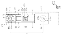
- the swing arm 23 is formed in a hollow, substantially rectangular column shape, and swings about a swing axis P extending in the facing direction.
- the swing arm 23 has a hollow swing center shaft portion 23a connected to the housing 21 at the upper part inside the housing 21 and a swing end connected to the translation stage 22a at the lower part inside the housing 21.
- the swing central shaft portion 23a is connected to the upper portion of the wall portion of the housing 21 at a position that coincides with the approximate center of the rail 22b in the transport direction.
- the axial direction of the swing center shaft portion 23a coincides with the swing axis P.
- a swing shaft support portion 23a1 that is formed in a cylindrical shape extending in the facing direction and supports the swing center shaft portion 23a in a state where it can rotate with respect to the housing 21 is located. is doing.
- the swing shaft support portion 23 a 1 is fixed to the housing 21. That is, the housing
- the connecting shaft portion 23b is connected to the outer surface of the wall portion facing the target in the translation stage 22a, and the connecting shaft portion 23b is connected to the outer surface of the translation stage 22a, for example, below the center thereof.
- the connecting shaft portion 23b rotates with respect to the translation stage 22a around a rotation axis A that coincides with a central axis extending along the facing direction.
- the connecting shaft portion 23 b is connected to the translation stage 22 a in a state where it can follow the translation of the cathode unit 22.
- the connecting shaft support portion 23b1 that is formed in a cylindrical shape extending in the facing direction and supports the connecting shaft portion 23b in a state where it can rotate with respect to the translation stage 22a is located outside the connecting shaft portion 23b.
- the connecting shaft support part 23b1 is fixed to the translation stage 22a. That is, the cathode unit 22 includes the connecting shaft support portion 23b1.
- the inside of the swing arm 23 and the inside of the translation stage 22a connected to the inside of the swing arm 23 are in an atmospheric pressure atmosphere.
- a vacuum seal is positioned between the outer peripheral surface of the swing central shaft portion 23a and the inner peripheral surface of the swing shaft support portion 23a1, and between the outer peripheral surface of the connection shaft portion 23b and the inner peripheral surface of the connection shaft support portion 23b1. Since the vacuum seal is located at the bottom, when the exhaust part 15 depressurizes the inside of the housing 21, the inside of the housing 21 is kept in a vacuum atmosphere.
- the connection line to be connected is located inside the swing arm 23 .
- the utility includes, for example, various power supplies, a gas cylinder of a process gas including a sputtering gas and a reactive gas, and a cooling water tank.
- the connection line may be, for example, a power line that supplies power to the target, a pipe through which cooling water that cools the target flows, or a pipe through which process gas supplied to the inside of the sputtering chamber 13 flows.
- FIG. 2 When the cathode device 18 starts to form a thin film, the translation stage 22 a is placed inside the housing 21 at one end in the transport direction of the rail 22 b, for example, at the left end in FIG. 2. positioned. At this time, the swing center shaft portion 23a of the swing arm 23 is connected to the upper portion of the wall portion of the housing 21 at a position that coincides with the approximate center of the rail 22b in the transport direction. On the other hand, the connecting shaft portion 23b of the swing arm 23 is located below the inside of the housing 21 at a position on the left end side of the rail 22b in the transport direction. Therefore, the direction in which the translation stage 22a extends perpendicularly to the rail 22b and the direction in which the swing arm 23 extends form a predetermined angle.
- the translation stage 22a moves along the rail 22b from one end portion in the transport direction perpendicular to the swing axis P to the other end portion.
- the translation stage 22a moves along the transport direction from the left end portion to the right end portion in FIG.
- the connecting shaft portion 23b of the swing arm 23 also translates with the translation stage 22a along the transport direction, so that the position of the connection shaft portion 23b in the transport direction is the position of the swing center shaft portion 23a in the transport direction. Get closer to.
- the angle formed by the extending direction of the translation stage 22a and the extending direction of the swing arm gradually decreases.
- both the swing center shaft portion 23a and the connecting shaft portion 23b rotate.
- the direction in which the rocking central shaft portion 23a rotates with respect to the casing 21 and the direction in which the connecting shaft portion 23b rotates with respect to the translation stage 22a are the same.
- the translation stage 22a translates with the connecting shaft portion 23b along the transport direction, and the position of the swing center shaft portion 23a in the transport direction and the position of the connection shaft portion 23b in the transport direction. And the direction in which the translation stage 22a extends overlaps the direction in which the swing arm 23 extends. As a result, the above-mentioned angle becomes 0 °.
- the position of the connecting shaft portion 23b in the transport direction is the position of the swing center shaft portion 23a in the transport direction. Move away from the position. As a result, the angle formed by the direction in which the translation stage 22a extends and the direction in which the swing arm 23 extends gradually increases.
- the swing central shaft portion 23a of the swing arm 23 is moved to the rail in the transport direction. It is located above the inside of the casing 21 at a position that coincides with the approximate center of 22b.
- the connecting shaft portion 23b of the swing arm 23 is positioned below the inside of the housing 21 at a position on the right end portion side of the rail 22b in the transport direction. Therefore, the angle formed by the direction in which the translation stage 22a extends and the direction in which the swing arm 23 extends is substantially the same as when the translation stage 22a is positioned at the left end of the rail 22b.
- the cathode unit 22 translates with the connecting shaft portion 23b in the transport direction from one end of the rail 22b toward the other end, or from the other end toward the one end.
- the swing arm 23 having the connecting shaft portion 23b as a swing end swings around the swing center shaft portion 23a.
- connection line passing through the inside of the housing 21 also follows the swing of the swing arm 23 to center the swing center shaft portion 23a. Swing as.
- the connection line located inside the swing arm 23 maintains the connection with the cathode unit 22 while following the swing of the swing arm 23.
- the connection line hardly goes in and out between the inside and the outside of the swing arm 23 through the swing center shaft portion 23a.
- the connection line located inside the swing arm 23 follows the swing of the swing arm 23 and keeps the connection with the cathode unit 22 while swinging about the swing center shaft portion 23a. For this reason, the connection line hardly goes in and out between the inside and the outside of the swing arm 23 through the swing center shaft portion 23a. Therefore, the amount of change in the length of the connection line that changes between the inside and the outside of the housing 21 may be smaller than the distance that the cathode unit 22 moves. As a result, it is possible to reduce the mechanical load that the connection line receives due to the entry / exit between the inside of the housing 21 and the outside of the housing 21.
- the first embodiment can also be implemented with appropriate modifications as follows.
- the position where the swinging central shaft portion 23a is connected to the wall portion of the housing 21 does not have to coincide with the approximate center of the rail 22b in the transport direction. If the swing arm 23 can swing, the position where the swing center shaft portion 23a is connected to the wall portion of the housing 21 is a position corresponding to one of the two ends of the rail 22b in the transport direction. Other positions may also be used.
- the cathode unit 22 is not limited to the configuration having the target formed in a flat plate shape facing the substrate S.
- the cathode unit 22 may have a rotating shaft that moves together with the translation stage 22a along the transport direction, and may include a target that is formed in a cylindrical shape having the rotating shaft as a central axis and faces the substrate S.
- the film forming apparatus may be embodied as various film forming apparatuses such as a vapor deposition apparatus having a vapor deposition source as a film forming unit, instead of the sputtering apparatus 10 including the cathode unit 22.
- the film forming apparatus may be embodied as various substrate processing apparatuses such as an ion beam irradiation apparatus including an ion beam irradiation unit as a processing unit, and a laser irradiation apparatus including various laser irradiation units such as ultraviolet rays as a processing unit. Good.
- the swing arm 23 includes an upper housing 31, a fixed plate 32, a guide tube portion 33, and a lower housing 34, and the upper housing 31, the fixed plate 32, and the guide tube portion 33.
- casing 34 is located in this order along the height direction which is one direction.
- the upper casing 31 is formed in a hollow rectangular column shape, and has a swing opening 31a that is connected to the swing center shaft portion 23a on one side surface and penetrates the side surface along the opposing direction.
- the upper housing 31 has an upper opening 31b that is a through hole extending along the height direction on the side surface facing the lower housing 34.
- the fixed plate 32 is formed in a rectangular plate shape and has a fixed opening 32a which is a through hole extending along the height direction.
- the fixed plate 32 is connected to the upper casing 31 with the fixed opening 32a and the upper opening 31b facing each other.
- each of the width along the facing direction and the width in the direction orthogonal to the paper surface is larger than that of the upper housing 31.
- the guide tube portion 33 is formed in a cylindrical shape extending along the height direction, and of the two end portions in the height direction, the end portion close to the fixed plate 32 faces the fixed opening portion 32a, and the fixed plate 32 is placed. It is fixed to.
- the lower housing 34 is formed in a hollow rectangular column shape, and is connected to the connecting shaft portion 23b on one side surface, and has a connecting opening 34a penetrating the side surface along the opposing direction.
- the lower housing 34 has a lower opening 34 b that is a through hole extending along the height direction on the side surface facing the upper housing 31.
- each of the width along the facing direction and the width in the direction orthogonal to the paper surface is substantially equal to the fixed plate 32.
- the swing center shaft portion 23 a is connected to the upper housing 31, and the swing shaft support portion 23 a 1 formed in a cylindrical shape covering the outer peripheral surface of the swing center shaft portion 23 a serves as the swing center shaft portion 23 a. It is pivotally supported in a state where it can rotate with respect to.
- the swinging shaft support 23a1 has a swinging flange 23a2 that extends radially outward from the outer peripheral surface in the middle of extending in the opposing direction, and the swinging flange 23a2 is fixed to the housing 21 by a fixing member. .
- the swing center shaft portion 23a is centered on the swing shaft P in a state where the outer peripheral surface of the swing center shaft portion 23a is in contact with the inner peripheral surface of the swing shaft support portion 23a1 via a bearing having a vacuum seal function. Rotates with respect to the casing 21.
- the connecting shaft portion 23 b is connected to the lower housing 34 and is formed in a cylindrical shape extending in the opposite direction to the swinging central shaft portion 23 a along the facing direction with respect to the guide tube portion 33.
- a connecting shaft support portion 23b1 formed in a cylindrical shape covering the outer peripheral surface of the connecting shaft portion 23b supports the connecting shaft portion 23b in a state where the connecting shaft portion 23b can be rotated with respect to the translation stage 22a.
- the connecting shaft support part 23b1 has a connecting flange 23b2 extending radially outward from the outer peripheral surface in the middle of extending in the facing direction, and the connecting flange 23b2 is fixed to the translation stage 22a by a fixing member.
- the connecting shaft portion 23b is connected to the translation stage 22a around the rotation axis A in a state where the outer peripheral surface of the connecting shaft portion 23b is in contact with the inner peripheral surface of the connecting shaft supporting portion 23b1 via a bearing having a vacuum sealing function. Rotate.
- the swing arm 23 includes a telescopic mechanism 40 that surrounds the guide tube portion 33 and includes the guide tube portion 33 between the upper housing 31 and the lower housing 34 in the height direction. Yes.
- the expansion / contraction mechanism 40 displaces the connecting shaft portion 23b with respect to the swinging central shaft portion 23a to extend and contract the distance between the swinging central shaft portion 23a and the connecting shaft portion 23b.
- the telescopic mechanism 40 includes a plurality of shafts 41 and the same number of shaft guides 42 as the shafts 41.
- the plurality of shaft guide portions 42 are positioned around the guide tube portion 33 at equal intervals, and each of the plurality of shaft guide portions 42 is formed in a cylindrical shape extending in the height direction.
- the cylindrical end close to the upper housing 31 faces a shaft through hole (not shown) formed in the fixed plate 32 extending in the height direction, and is fixed to the fixed plate 32. It is fixed to.
- Each of the plurality of shafts 41 is formed in a columnar shape extending along the height direction.
- the end portion close to the upper housing 31 is passed through one shaft guide portion 42 and the shaft through hole of the fixing plate 32, and the end portion close to the lower housing 34 is
- the lower casing 34 is fixed to the side surface facing the upper casing 31.
- connection lines 50 extending from the swing central shaft portion 23a toward the connecting shaft portion 23b pass through the swing arm 23.
- Each of the plurality of connection lines 50 may be a single line or may be composed of a plurality of line components connected to each other by a terminal.
- the plurality of connection lines 50 include a power line 51 that supplies high-frequency power to the backing plate of the cathode unit 22, a gas pipe 52 that supplies process gas around the cathode unit 22, and a cooling water pipe that supplies cooling water to the backing plate. 53.
- the number of each of the power lines 51, the gas pipes 52, and the cooling water pipes 53 included in the connection line 50 may be one or plural.
- the power line 51 has a rigid body portion 51a fixed inside the swing arm 23 in a state where the shape does not change, and a flexible portion 51b that is housed inside the lower housing 34 and changes its shape.
- the rigid body portion 51a extends from the outside of the swing central shaft portion 23a toward the lower housing 34 and is connected to one end portion of the flexible portion 51b, and the other end portion of the flexible portion 51b.
- a connecting rigid body portion 51a2 extending from the lower housing 34 to the outside of the connecting shaft portion 23b.
- the swinging rigid body portion 51a1 and the connecting rigid body portion 51a2 are an example of an intermediate rigid body wiring
- the flexible portion 51b is an example of an intermediate flexible line.
- the gas pipe 52 has a bent portion 52 a having a curved shape, and the bent portion 52 a is located inside the lower housing 34.
- the cooling water pipe 53 has a bent portion 53 a having a curved shape, and the bent portion 53 a is located inside the lower housing 34.
- the telescopic mechanism 40 of the swing arm 23 will be described in more detail with reference to FIGS.
- the telescopic mechanism 40 includes a guide cylinder portion 33, four shafts 41 (only two shafts 41 are shown in FIG. 6), and four shaft guide portions 42. .
- the four shafts 41 and the four shaft guide portions 42 are located corresponding to the four corners of the fixed plate 32.
- the guide tube portion 33 has an upper tube portion 33 a that is formed in a cylindrical shape and is fixed to the fixing plate 32, and a lower tube portion 33 b that is formed in a cylindrical shape and is fixed to the lower housing 34.
- the guide tube portion 33 includes a bellows 33c formed in a cylindrical shape between the upper tube portion 33a and the lower tube portion 33b in the height direction.
- the bellows 33c has one cylinder end connected to the upper cylinder part 33a and the other cylinder end connected to the lower cylinder part 33b.
- the bellows 33c is urged in the height direction in a direction from the lower cylindrical portion 33b toward the upper cylindrical portion 33a.
- the telescopic mechanism 40 shortens the distance between the swing center shaft portion 23a and the connection shaft portion 23b in the swing arm 23 in accordance with the distance between the swing center shaft portion 23a and the connection shaft support portion 23b1. That is, the telescopic mechanism 40 minimizes the length L of the swing arm, which is the distance between the swing center shaft portion 23a and the connecting shaft portion 23b.
- each shaft 41 and the lower cylinder part 33b fixed to the bellows 33c move to the position closest to the fixed plate 32 in the height direction together with the lower casing 34.
- the bending amount in the bending portion 52a of the gas pipe 52 becomes the largest, and the bending amount in the bending portion 53a of the cooling water pipe 53 becomes the largest.
- the amount of bending at each of the two bending portions 52a and 53a increases as the position of the translation stage 22a in the transport direction approaches the position of the swinging central shaft portion 23a of the swing arm 23 in the transport direction.
- the telescopic mechanism 40 extends the distance between the swing center shaft portion 23a and the connection shaft portion 23b in the swing arm 23 in accordance with the distance between the swing center shaft portion 23a and the connection shaft support portion 23b1. That is, the telescopic mechanism 40 maximizes the length L of the swing arm 23, which is the distance between the swing center shaft portion 23a and the connecting shaft portion 23b.
- each shaft 41 and the lower cylinder part 33b fixed to the bellows 33c move to a position farthest from the fixed plate 32 in the height direction together with the lower casing 34.
- the bending amount in the bending portion 52a of the gas pipe 52 becomes the smallest, and the bending amount in the bending portion 53a of the cooling water pipe 53 becomes the smallest.
- the amount of flexure at each of the two flexures 52a and 53a decreases as the position of the translation stage 22a in the transport direction becomes farther from the position of the swing central shaft portion 23a of the swing arm 23 in the transport direction.
- the telescopic mechanism 40 of the swing arm 23 corresponds to the position of the connecting shaft portion 23b that translates with the translation stage 22a, that is, between the swing center shaft portion 23a of the swing arm 23 and the connecting shaft support portion 23b1.
- the length L of the swing arm 23 is changed according to the distance between them. That is, when the cathode unit 22 translates with the translation stage 22a, the length of the swing arm 23 extends or contracts between the swing center shaft portion 23a and the connecting shaft portion 23b.
- the telescopic mechanism 40 of the swing arm 23 matches the distance between the swing center shaft portion 23a and the connecting shaft portion 23b with the distance between the swing center shaft portion 23a and the connecting shaft support portion 23b1. Change. Thereby, the connection shaft part 23b provided in the swing arm 23 can follow the movement of the translation stage 22a.
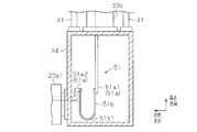
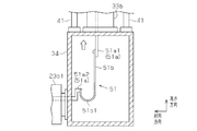
- FIGS. 8 and 9 show the configuration of the power line 51 when the length L of the swing arm 23 is the smallest, while FIG. 9 shows the state of the power line 51 when the length L of the swing arm 23 is the largest. The state is shown.
- the power line 51 is composed of a plurality of components, and the plurality of components includes a swinging rigid body portion 51a1, a flexible portion 51b, and a connecting rigid body portion 51a2.
- the swinging rigid part 51a1 is formed in a strip shape extending from the swinging central shaft part 23a toward the lower housing 34, and the main component of the forming material in the swinging rigid part 51a1 is, for example, copper.
- the main component of the forming material in the swinging rigid part 51a1 is, for example, copper.
- the two ends of the swing rigid body 51 a 1 one end is connected to a power line disposed outside the swing arm 23, and the other end is connected to the flexible portion 51 b inside the swing arm 23. Connected.
- the swinging rigid part 51a1 passes through the inside of the guide tube part 33, and the other end of the swinging rigid part 51a1 protrudes from the lower opening 34b of the lower casing 34 toward the bottom of the lower casing 34.
- the swinging rigid body portion 51a1 is fixed to the inside of the upper housing 31 or the upper cylindrical portion 33a of the swinging arm 23 while extending from the swinging central shaft portion 23a toward the lower housing 34. Yes.
- the connecting rigid body portion 51a2 is formed in a strip shape extending from the lower housing 34 to the connecting shaft portion 23b, and the main component of the forming material in the connecting rigid body portion 51a2 is, for example, copper. Of the two ends of the connecting rigid body 51 a 2, one end is connected to the flexible portion 51 b inside the swing arm 23, and the other end is connected to a power line arranged outside the swing arm 23. is doing. Although not shown, the connecting rigid body portion 51a2 is fixed inside the swing arm 23 in the middle of extending from the lower housing 34 toward the connecting shaft portion 23b. When the expansion / contraction mechanism 40 expands / contracts the swing arm 23 in accordance with the swing of the swing arm 23, the flexible portion 51b expands / contracts the distance between the swing rigid body portion 51a1 and the connecting rigid body portion 51a2.
- the flexible portion 51b is disposed inside the lower housing 34, and is formed in a belt shape in which one end of the two ends is connected to the swinging rigid portion 51a1 and the other end is connected to the connecting rigid portion 51a2. ing.
- the flexible part 51b is constituted by, for example, a flat knitted copper wire in which a plurality of copper wires are knitted in a band shape, and has flexibility.
- the flexible portion 51b has a curved portion 51b1 that is a portion bent by its own weight.
- the flexible part 51b has a distance from one end of the flexible part 51b connected to the swinging rigid part 51a1 to the curved part 51b1, and the other end of the flexible part 51b connected to the connecting rigid part 51a2. Is deformed so that the distance from the curved portion 51b1 to the curved portion 51b1 becomes substantially equal. That is, the bending amount of the flexible portion 51b is the largest.
- the flexible portion 51b has the longest distance from one end of the flexible portion 51b connected to the swinging rigid portion 51a1 to the curved portion 51b1, and the flexible portion 51b connected to the connecting rigid portion 51a2 It deform
- the swing arm 23 expands and contracts, the amount of flexure of the flexible portion 51b changes between the swing rigid portion 51a1 and the connecting rigid portion 51a2. Therefore, the change in the difference between the length of the power line 51 passing through the inside of the swing arm 23 and the length of the swing arm 23 is absorbed by the change in the deflection amount of the flexible portion 51b. Therefore, the length of the power line 51 that enters and exits between the inside and the outside of the swing arm 23 is shortened.
- the effects listed below can be obtained.
- the telescopic mechanism 40 of the swing arm 23 determines the distance between the swing center shaft portion 23a and the connecting shaft portion 23b as the swing center shaft portion 23a.
- the connecting shaft support 23b1 are changed in accordance with the distance. Thereby, the connection shaft part 23b provided in the swing arm 23 can follow the movement of the translation stage 22a.
- each of the bent portion 52a of the gas pipe 52 and the bent portion 53a of the cooling water pipe 53 is not embodied as a portion having a curved shape in each of the gas pipe 52 and the cooling water pipe 53.
- the connection line may be embodied as a part having a spiral shape.
- the spiral shape may be a two-dimensional spiral shape or a three-dimensional spiral shape.
- the configuration of the power line 51 may be applied to at least one of other lines included in the connection line 50, for example, the gas pipe 52 and the cooling water pipe 53.
- the sputtering apparatus may be embodied as a combination of the configuration described in the first embodiment and the configuration described in the second embodiment. According to such a configuration, the sputtering apparatus can be embodied as a configuration having both the effect of the first embodiment and the effect of the second embodiment.
- the swing arm 23 does not have to include the telescopic mechanism 40.
- the guide tube portion 33 may be embodied as one cylindrical tube portion.
- a connecting portion for example, an elastic member such as a spring
- a connecting portion that increases the distance between the swinging central shaft portion 23a and the housing 21 as the cathode unit 22 is translated may be provided.
- the swing arm 23 may not include the expansion / contraction mechanism 40.
- a communication part for example, an elastic member such as a spring
- the guide tube portion 33 may be embodied as one cylindrical tube portion. Even with such a configuration, as long as the swing arm 23 swings about the swing center shaft portion 23a, it is possible to obtain an effect according to the above-described (1).
- the swing arm 23 does not have to be provided with the expansion / contraction mechanism 40, and is provided between the connection shaft portion 23b and the translation stage 22a and between the swing center shaft portion 23a and the casing 21 as described above.
- the structure provided with a connection part (for example, elastic members, such as a spring), may be sufficient.
- the guide tube portion 33 may be embodied as one cylindrical tube portion. Even with such a configuration, as long as the swing arm 23 swings about the swing center shaft portion 23a, it is possible to obtain an effect according to the above-described (1).
- the power line 51 may include not only a conductor but also a terminal block that is an insulator positioned between two conductors as a component of the power line 51.
- a terminal block that supports the swinging rigid body part 51a1 and the flexible part 51b may be positioned between the swinging rigid body part 51a1 and the flexible part 51b in an electrically connected state.
- a terminal block that supports the connection rigid body part 51a2 and the flexible part 51b in a state of being electrically connected may be located.
- FIGS. 10 to 13 A third embodiment in which the substrate processing apparatus and the film forming apparatus are embodied as a sputtering apparatus will be described with reference to FIGS. 10 to 13.
- the sputtering apparatus of the third embodiment is characterized by a power line attached to the swing center shaft portion 23a of the swing arm 23 and a power line attached to the connecting shaft portion 23b of the swing arm 23. Therefore, below, these structures are demonstrated.
- 10 to 13 a sputtering apparatus having two power lines 51 is shown as an example.
- FIGS. 10 shows the state of the power line 51 when the length L of the swing arm 23 is the smallest
- FIG. 11 shows the state of the power line 51 when the length L of the swing arm 23 is the largest. The state is shown.
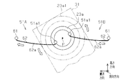
- the power line 51 includes a first power line 51A and a second power line 51B, and the first power line 51A and the second power line 51B pass through the swing axis P and extend in the height direction.
- Each of the swinging rigid body portions 51a1 constituting each power line 51 is formed in a band shape and swings from the inside of the upper housing 31 in a state of being separated from the inner peripheral surface of the swinging central shaft portion 23a extending along the facing direction. It extends toward the cylinder end of the moving center shaft portion 23a.
- each swinging rigid body portion 51a1 that passes through the swinging central shaft portion 23a extends along the swinging shaft P, so that deformation due to swinging of the swinging arm 23 can be suppressed.
- the end of each swing rigid body 51a1 is fixed to the end surface of the swing center shaft 23a via an insulator at the cylindrical end of the swing center shaft 23a.
- the swing center shaft portion 23a is an example of a base end rotation portion, and the swing rigid body portion 51a1 is an example of a base end rotation wiring.
- Each of the first power line 51A and the second power line 51B is fixed to a wall portion of the sputtering chamber 13, for example, the wall portion of the casing 21 fixed to the swinging flange 23a2 via an insulator and connected to another power line.
- fixed part 61 to have is provided.
- the swing fixing portion 61 is an example of a base end fixing wiring.
- Each of the first power line 51A and the second power line 51B has an oscillating flexible part 62 connected to the end of the oscillating rigid body part 51a1 and the oscillating fixing part 61.
- Each swinging flexible part 62 is formed in a substantially arc shape extending along the transport direction, and is made of, for example, a flat knitted copper wire having flexibility.
- the swinging flexible part 62 has a curved part 62a that is bent by its own weight toward the lower housing 34 in the height direction.
- the length of the bending portion 62a formed on the swinging flexible portion 62 that deforms according to the distance between the end of the swinging rigid body portion 51a1 and the swinging fixed portion 61 corresponds to the amount of bending of the bending portion 62a.
- the swinging flexible part 62 is an example of a proximal end flexible line.
- each swing flexible part 62 has a distance from the swing rigid body part 51a1 to the curved part 62a in the transport direction, and a swing fixed.
- the deformation is performed so that the distance from the portion 61 to the curved portion 62a is substantially equal. That is, when the distance between the end of the swinging rigid body portion 51a1 and the swinging fixed portion 61 is the shortest, the bending amount of each bending portion 62a is the largest.
- the swing center shaft portion 23a swings around the swing axis P.
- the end of the swing rigid body portion 51a1 in the first power line 51A moves downward along the circumferential direction of the swing center shaft portion 23a.
- the end of the rocking rigid part 51a1 in the second power line 51B moves upward along the circumferential direction of the rocking central shaft part 23a.
- the distance between the end of the oscillating rigid body portion 51a1 and the oscillating fixing portion 61 is increased, and the bending amount of each bending portion 62a is decreased.
- FIGS. 12 shows the state of the power line 51 when the length L of the swing arm 23 is the smallest
- FIG. 13 shows the state of the power line 51 when the length L of the swing arm 23 is the largest. The state is shown.
- each of the connecting rigid body portions 51a2 constituting the power line 51 is formed in a band shape, and is separated from the inner peripheral surface of the connecting shaft portion 23b extending in the facing direction, and the lower casing 34 is separated. Extends from the inside toward the tube end of the connecting shaft portion 23b. That is, a portion of each connecting rigid body portion 51a2 that passes through the connecting shaft portion 23b extends along the rotation axis A, so that deformation due to the swing of the swing arm 23 can be suppressed.
- Each connecting rigid body portion 51a2 is fixed to the end surface of the connecting shaft portion 23b via an insulator at the cylindrical end of the connecting shaft portion 23b.
- the connecting shaft portion 23b is an example of the tip rotating portion
- the connecting rigid body portion 51a2 is an example of the tip rotating wiring.
- Each of the first power line 51A and the second power line 51B has a connecting translation portion 71 that translates following the translation of the cathode unit 22 and the connecting shaft portion 23b.
- the connection translation part 71 is fixed to one side surface of the translation stage 22a, for example, the inner side surface of the side wall of the translation stage 22a fixed to the connection shaft support part 23b1, via an insulator, and connected to another power line.
- the connection translation part 71 is an example of a tip translation wiring.
- Each of the first power line 51A and the second power line 51B has a connecting flexible part 72 connected to the end of the connecting rigid body part 51a2 and the connecting translation part 71.
- Each connecting flexible portion 72 extends downward from the end of the connecting rigid body portion 51a2 along the height direction, is folded halfway, and extends upward to the connecting translation portion 71 along the height direction.
- Each connecting flexible portion 72 has a folded portion 72a that is bent by its own weight below the connecting translation portion 71 along the height direction.
- the length of the folded portion 72a formed in the connecting flexible portion 72 that is deformed according to the distance between the end of the connecting rigid body portion 51a2 and the connecting translation portion 71, that is, in the height direction relative to the connecting translation portion 71.
- the length of the folded portion 72a located below corresponds to the amount of bending of the folded portion 72a.
- Each connection flexible part 72 is comprised by the flat knitted copper wire which has flexibility, for example.
- the connecting flexible part 72 is an example of a tip flexible line.
- the connecting shaft portion 23b rotates about the rotation axis A with respect to the translation stage 22a.
- the connecting shaft portion 23b swings clockwise in the drawing, the end of the connecting rigid body portion 51a2 in the first power line 51A moves downward along the circumferential direction of the connecting shaft portion 23b, and the second power line 51B.
- the end portion of the connecting rigid body portion 51a2 moves upward along the circumferential direction of the connecting shaft portion 23b.
- connection rigid body part 51a2 the distance between the end of the connection rigid body part 51a2 and the connection translation part 71 is reduced, while in the second power line 51B, the end of the connection rigid body part 51a2 and the connection translation part 71 The distance between becomes larger.
- the amount of bending in connection flexible part 72 becomes large
- the amount of bending in connection flexible part 72 becomes small.
- the power line 51 is suppressed from being twisted by the rotation of the connecting shaft portion 23b, the mechanical load received by the power line 51 can be reduced.
- the effects listed below can be obtained.
- Each of the first power line 51 ⁇ / b> A and the second power line 51 ⁇ / b> B may be configured not to include the connecting flexible portion 72, and each of the connecting rigid body portions 51 a 2 may be connected to the connecting translational portion 71. Even if it is such a structure, if each of the 1st power line 51A and the 2nd power line 51B is the structure provided with the rocking
- Each of the first power line 51A and the second power line 51B may not be provided with the swinging flexible part 62, and each of the swinging rigid body parts 51a1 may be connected to the swinging fixing part 61. Even if it is such a structure, if each of the 1st power line 51A and the 2nd power line 51B is the structure provided with the connection flexible part 72, the effect according to above-mentioned (5) can be acquired.
- a terminal (hereinafter referred to as a utility connection terminal) that is formed in an annular shape around the swing axis P and is connected to a utility is attached to the end surface of the swing center shaft portion 23a of the swing arm 23 via an insulator. Also good.
- the end portion close to the swinging central shaft portion 23a is connected to the utility connection terminal in a state where the end portion can move along the circumferential direction of the utility connection terminal. And it is sufficient. According to such a configuration, it is possible to prevent the end portion of the connection line 50 connected to the utility connection terminal from being deformed as the swing arm 23 swings.
- a terminal (hereinafter referred to as a “cathode unit connection terminal”) that is formed in an annular shape around the rotation axis A and is connected to the cathode unit 22 disposed inside the housing 21 is an end face of the coupling shaft portion 23 b of the swing arm 23. It may be attached via an insulator.
- the end portion close to the connecting shaft portion 23b is connected to the cathode unit connection terminal in a state where it can move along the circumferential direction of the cathode unit connection terminal. And it is sufficient. According to such a configuration, the end of the connection line 50 connected to the cathode unit connection terminal can be prevented from being deformed as the swing arm 23 swings.
- Each of the first power line 51A and the second power line 51B may include not only a conductor but also a terminal block that is an insulator positioned between the two conductors as a constituent element.
- each of the first power line 51 ⁇ / b> A and the second power line 51 ⁇ / b> B may include a terminal block that is an insulator positioned between one of the conductors included in the component and a power source located outside the housing 21. .
- the configuration of the first power line 51 ⁇ / b> A and the second power line 51 ⁇ / b> B may be applied to the gas pipe 52 and the cooling water pipe 53 that are other lines included in the connection line 50 instead of the power line 51.
- the sputtering apparatus may be embodied as a combination of the configuration described in the first embodiment and the configuration described in the third embodiment. According to such a configuration, the sputtering apparatus can be embodied as a configuration having both the effects of the first embodiment and the effects of the third embodiment.
- the sputtering apparatus may be embodied as a configuration combining the configuration described in the first embodiment, the configuration described in the second embodiment, and the configuration described in the third embodiment. According to such a configuration, the sputtering apparatus can be embodied as a configuration having all of the effects of the first embodiment, the effects of the second embodiment, and the effects of the third embodiment.
- connection flange 31 ... Upper housing, 31a ... Oscillating opening portion, 31b ... Upper opening portion, 32 ... Fixing plate, 32a ... Fixing opening portion, 33 ... Guide Tube part, 33a ... Upper cylinder part, 33b ... Lower cylinder part, 33c ... Bellows, 34 ... Lower housing, 34a ... Connection opening part, 34b ... Lower opening part, 40 ... Telescopic mechanism, 41 ... Sha 41a ... upper end part, 42 ... shaft guide part, 50 ... connection line, 51 ... power line, 51a ... rigid body part, 51a ... rocking rigid body part, 51a2 ... coupling rigid body part, 51b ... flexible part, 51b1, 61a ...
Landscapes
- Chemical & Material Sciences (AREA)
- Engineering & Computer Science (AREA)
- Physics & Mathematics (AREA)
- Plasma & Fusion (AREA)
- Analytical Chemistry (AREA)
- Chemical Kinetics & Catalysis (AREA)
- Materials Engineering (AREA)
- Mechanical Engineering (AREA)
- Metallurgy (AREA)
- Organic Chemistry (AREA)
- Physical Vapour Deposition (AREA)
Abstract
Description
本開示の技術は、基板を処理する処理部に接続した接続ラインが筐体の内部と筐体の外部との間の出入に起因して受ける機械的な負荷を小さくすることができる基板処理装置、および、成膜装置を提供することを目的とする。
好ましくは、上記基板処理装置において、前記連結軸部は、前記揺動中心軸部の軸方向に沿った回転軸を中心として前記処理部に対して回転する先端回転部として設けられる。また、好ましくは、前記接続ラインは、前記先端回転部に固定され、前記先端回転部の回転に追従して回転する剛体である先端回転配線と、前記処理部に固定され、前記処理部の移動に追従して該処理部と並進する剛体である先端並進配線と、自重により撓み可能に設けられ、前記先端回転配線と前記先端並進配線との間に接続されて、前記先端回転配線と前記先端並進配線との間の距離の増大に応じて撓み量を小さくする先端可撓ラインとを備える。
図1から図4を参照して基板処理装置および成膜装置をスパッタ装置として具体化した第1実施形態を説明する。以下では、スパッタ装置の全体構成の一例、スパッタ装置の備えるカソード装置、および、カソード装置の作用を順に説明する。
図1を参照してスパッタ装置の全体構成の一例を説明する。
図1に示されるように、スパッタ装置10は、搬出入チャンバ11、前処理チャンバ12、および、スパッタチャンバ13を備え、3つのチャンバは、1つの方向である搬送方向に沿って並んでいる。スパッタ装置10は、搬出入チャンバ11と前処理チャンバ12との間、および、前処理チャンバ12とスパッタチャンバ13との間の各々を繋ぐ2つのゲートバルブ14を備えている。3つのチャンバの各々は、各チャンバを減圧する排気部15を搭載している。3つのチャンバの各々の底面には、搬送方向に沿って延びる相互に平行な2つのレーンである成膜レーン16と回収レーン17とが取り付けられている。
図2を参照してカソード装置18を説明する。なお、図2から図4では、説明の便宜上、スパッタチャンバ13を構成する筐体が有する壁部であって、搬送方向に平行な壁部の図示が省略されている。
図2から図4を参照してカソード装置の作用を説明する。
図2に示されるように、カソード装置18が薄膜の形成を開始するとき、並進ステージ22aは、筐体21の内部にて、レール22bにおける搬送方向の一端部、例えば、図2における左端部に位置している。このとき、揺動アーム23の揺動中心軸部23aは搬送方向におけるレール22bの略中央に一致する位置において筐体21の壁部の上方に接続されている。一方、揺動アーム23の連結軸部23bは搬送方向におけるレール22bの左端部側の位置にて筐体21の内部における下方に位置している。そのため、並進ステージ22aがレール22bに対し垂直に延びる方向と、揺動アーム23の延びる方向とが、所定の角度を形成している。
(1)カソードユニット22が連結軸部23bと並進するとき、揺動アーム23が揺動する。この際、揺動アーム23の内部に位置する接続ラインは、揺動アーム23の揺動に追従して、揺動中心軸部23aを中心として揺動しながらカソードユニット22との接続を保つ。このため、接続ラインは、揺動中心軸部23aを通じて揺動アーム23の内部と外部との間をほとんど出入りしない。そのため、筐体21の内部と外部との間で変化する接続ラインの長さの変化量は、カソードユニット22が移動する距離よりも小さくて済む。結果として、筐体21の内部と筐体21の外部との間の出入に起因して接続ラインが受ける機械的な負荷を小さくすることができる。
・揺動中心軸部23aが筐体21の壁部に接続される位置は、搬送方向におけるレール22bの略中央に一致する位置でなくともよい。揺動アーム23が揺動することができれば、揺動中心軸部23aが筐体21の壁部に接続される位置は、搬送方向におけるレール22bの2つの端部のいずれかに対応する位置や、その他の位置でもよい。
図5から図9を参照して基板処理装置および成膜装置をスパッタ装置として具体化した第2実施形態を説明する。揺動アーム23の揺動中心軸部23aと連結軸部23bとの間の距離は、揺動中心軸部23aと連結軸支部23b1との間の距離に合わせて変わる。そのため、以下では、こうした距離の変更に関わる構成を詳しく説明する。また、以下では、揺動アーム23の全体構成、揺動アーム23の伸縮機構、および、接続ラインの一例である電力線の詳細な構成を順に説明する。
図5を参照して揺動アーム23の全体構成を内部構成とともに説明する。
図5に示されるように、揺動アーム23は、上部筐体31、固定板32、案内筒部33、および、下部筐体34を備え、上部筐体31、固定板32、案内筒部33、および、下部筐体34は、1つの方向である高さ方向に沿ってこの順に並んでいる。
図6および図7を参照して揺動アーム23の伸縮機構40をより詳しく説明する。
図6に示されるように、伸縮機構40は、案内筒部33と、4本のシャフト41(図6では2本のシャフト41のみを示す)と、4つのシャフト案内部42とを備えている。4つのシャフト41、および、4つのシャフト案内部42は、固定板32の四隅に対応して位置している。
案内筒部33は、高さ方向における上部筒部33aと下部筒部33bとの間に円筒状に形成されたベローズ33cを備えている。ベローズ33cは、上部筒部33aに接続される一方の筒端と、下部筒部33bに接続される他方の筒端とを有している。ベローズ33cは、高さ方向にて下部筒部33bから上部筒部33aに向かう方向に付勢されている。
図8および図9を参照して電力線51の構成をより詳しく説明する。なお、図8には、揺動アーム23の長さLが最も小さいときの電力線51の状態が示される一方、図9には、揺動アーム23の長さLが最も大きいときの電力線51の状態が示されている。
(2)並進ステージ22aが連結軸部23bと並進するとき、揺動アーム23の伸縮機構40が、揺動中心軸部23aと連結軸部23bとの間の距離を、揺動中心軸部23aと連結軸支部23b1との間の距離に合わせて変化させる。これにより、揺動アーム23に設けられた連結軸部23bは、並進ステージ22aの移動に追従できる。
・ガス配管52の撓み部52a、および、冷却水配管53の撓み部53aの各々は、ガス配管52および冷却水配管53の各々にて湾曲形状を有する部位として具体化されるのではなく、例えば、接続ラインにて螺旋形状を有する部分として具体化されてもよい。なお、螺旋形状は、二次元的な螺旋形状であってもよいし、三次元的な螺旋形状であってもよい。
・スパッタ装置は、第1実施形態に記載の構成と、第2実施形態に記載の構成とを組み合わせた構成として具体化されてもよい。こうした構成によれば、第1実施形態による効果と、第2実施形態による効果との両方を有する構成としてスパッタ装置を具体化することができる。
図10から図13を参照して基板処理装置および成膜装置をスパッタ装置として具体化した第3実施形態を説明する。第3実施形態のスパッタ装置は、揺動アーム23の揺動中心軸部23aに取り付けられた電力線、および、揺動アーム23の連結軸部23bに取り付けられた電力線に特徴を有する。そのため、以下では、これらの構成について説明する。なお、図10から図13では、電力線51が2本であるスパッタ装置が一例として示されている。
図10および図11を参照して揺動中心軸部23aに取り付けられた電力線51を説明する。なお、図10には、揺動アーム23の長さLが最も小さいときの電力線51の状態が示される一方、図11には、揺動アーム23の長さLが最も大きいときの電力線51の状態が示されている。
[連結軸部の電力線]
図12および図13を参照して連結軸部23bに取り付けられた電力線51を説明する。なお、図12には、揺動アーム23の長さLが最も小さいときの電力線51の状態が示される一方、図13には、揺動アーム23の長さLが最も大きいときの電力線51の状態が示されている。
以上説明したように、第3実施形態のスパッタ装置によれば、以下に列挙する効果を得ることができる。
・第1電力線51Aおよび第2電力線51Bの各々が、連結可撓部72を備えていない構成でもよく、連結剛体部51a2の各々が、連結並進部71に接続する構成でもよい。こうした構成であっても、第1電力線51Aおよび第2電力線51Bの各々が、揺動可撓部62を備える構成であれば、上述の(4)に準じた効果を得ることはできる。
・スパッタ装置は、第1実施形態に記載の構成と、第3実施形態に記載の構成とを組み合わせた構成として具体化されてもよい。こうした構成によれば、第1実施形態による効果と、第3実施形態による効果との両方を有する構成としてスパッタ装置を具体化することができる。
Claims (6)
- 筐体と、
前記筐体の内部に位置する中空の揺動アームであって、前記筐体に接続される中空の揺動中心軸部と、揺動端である中空の連結軸部とを含む前記揺動アームと、
前記筐体の内部に位置し、基板と向かい合う処理空間を前記揺動中心軸部の軸方向と直交する方向に移動して前記基板に処理を施す処理部であって、前記処理部の移動に追従して前記連結軸部が前記処理部と並進可能となるように前記連結軸部に連結され、前記処理部の移動によって前記揺動アームを揺動させる前記処理部と、
前記揺動アームの内部に位置し、前記揺動中心軸部内を通じて前記筐体の外部に位置するユーティリティに接続され、かつ前記連結軸部内を通じて前記処理部に接続される接続ラインと、
を備える基板処理装置。 - 前記処理部は、前記連結軸部を前記処理部に対して回転可能に支持する軸支部を備え、
前記揺動アームは、前記揺動中心軸部に対し前記連結軸部を変位させて前記揺動中心軸部と前記連結軸部との間の距離を伸縮する伸縮機構を備え、
前記伸縮機構は、前記揺動中心軸部と前記連結軸部との間の距離を前記揺動中心軸部と前記軸支部との間の距離に合わせるように変化させる、
請求項1に記載の基板処理装置。 - 前記接続ラインは、複数のライン構成要素から構成され、
前記複数のライン構成要素は、
前記揺動アームの内部に配置されるとともに、前記揺動アームに個別に固定され、前記伸縮機構による前記揺動アームの伸縮に合わせて、互いの間の距離を伸縮する2つの中間剛体配線と、
前記揺動アームの内部に配置されるとともに、前記2つの中間剛体配線の間に接続され、可撓性を有して前記2つの中間剛体配線の間の距離の増大に応じて撓み量を小さくする中間可撓ラインと、を含む、
請求項2に記載の基板処理装置。 - 前記揺動中心軸部は、前記揺動中心軸部の軸方向に沿った回転軸を中心として前記筐体に対して回転する基端回転部として設けられ、
前記接続ラインは、
前記基端回転部に固定され、前記基端回転部の回転に追従して回転する剛体である基端回転配線と、
前記筐体に固定される剛体である基端固定配線と、
自重により撓み可能に設けられ、前記基端回転配線と前記基端固定配線との間に接続されて、前記基端回転配線と前記基端固定配線との間の距離の増大に応じて撓み量を小さくする基端可撓ラインと、を備える、
請求項1~3のいずれか一項に記載の基板処理装置。 - 前記連結軸部は、前記揺動中心軸部の軸方向に沿った回転軸を中心として前記処理部に対して回転する先端回転部として設けられ、
前記接続ラインは、
前記先端回転部に固定され、前記先端回転部の回転に追従して回転する剛体である先端回転配線と、
前記処理部に固定され、前記処理部の移動に追従して該処理部と並進する剛体である先端並進配線と、
自重により撓み可能に設けられ、前記先端回転配線と前記先端並進配線との間に接続されて、前記先端回転配線と前記先端並進配線との間の距離の増大に応じて撓み量を小さくする先端可撓ラインと、を備える、
請求項1~4のいずれか一項に記載の基板処理装置。 - 筐体と、
前記筐体の内部に位置する中空の揺動アームであって、前記筐体に接続される中空の揺動中心軸部と、揺動端である中空の連結軸部とを含む前記揺動アームと、
前記筐体の内部に位置し、基板と向かい合う処理空間を前記揺動中心軸部の軸方向と直交する方向に移動して、前記基板に向けて成膜材料を放出することによって前記基板上に膜を形成する成膜部であって、前記成膜部の移動に追従して前記連結軸部が前記成膜部と並進可能となるように前記連結軸部に連結され、前記成膜部の移動によって前記揺動アームを揺動させる前記成膜部と、
前記揺動アームの内部に位置し、前記揺動中心軸部内を通じて前記筐体の外部に位置するユーティリティに接続され、かつ前記連結軸部内を通じて前記成膜部に接続される接続ラインと、
を備える成膜装置。
Priority Applications (4)
| Application Number | Priority Date | Filing Date | Title |
|---|---|---|---|
| JP2015539136A JP6009685B2 (ja) | 2013-09-26 | 2014-09-17 | 基板処理装置、および、成膜装置 |
| KR1020167008733A KR101763906B1 (ko) | 2013-09-26 | 2014-09-17 | 기판처리 장치, 및 성막(成膜) 장치 |
| KR1020177003025A KR20170017004A (ko) | 2013-09-26 | 2014-09-17 | 기판처리 장치, 및 성막(成膜) 장치 |
| CN201480047603.5A CN105555996B (zh) | 2013-09-26 | 2014-09-17 | 基板处理装置以及成膜装置 |
Applications Claiming Priority (2)
| Application Number | Priority Date | Filing Date | Title |
|---|---|---|---|
| JP2013-200558 | 2013-09-26 | ||
| JP2013200558 | 2013-09-26 |
Publications (1)
| Publication Number | Publication Date |
|---|---|
| WO2015045980A1 true WO2015045980A1 (ja) | 2015-04-02 |
Family
ID=52743121
Family Applications (1)
| Application Number | Title | Priority Date | Filing Date |
|---|---|---|---|
| PCT/JP2014/074525 Ceased WO2015045980A1 (ja) | 2013-09-26 | 2014-09-17 | 基板処理装置、および、成膜装置 |
Country Status (5)
| Country | Link |
|---|---|
| JP (1) | JP6009685B2 (ja) |
| KR (2) | KR101763906B1 (ja) |
| CN (1) | CN105555996B (ja) |
| TW (1) | TWI575095B (ja) |
| WO (1) | WO2015045980A1 (ja) |
Citations (5)
| Publication number | Priority date | Publication date | Assignee | Title |
|---|---|---|---|---|
| JP2009299176A (ja) * | 2008-06-16 | 2009-12-24 | Samsung Mobile Display Co Ltd | 移送装置及びこれを備える有機物蒸着装置 |
| JP2010040956A (ja) * | 2008-08-08 | 2010-02-18 | Tokyo Electron Ltd | 基板の処理装置 |
| JP2010080230A (ja) * | 2008-09-25 | 2010-04-08 | Hitachi High-Technologies Corp | 有機elデバイス製造装置及び成膜装置並びに真空内配線・配管機構 |
| WO2011135731A1 (ja) * | 2010-04-28 | 2011-11-03 | 株式会社ユーテック | 基板処理装置及び薄膜の製造方法 |
| JP2012012626A (ja) * | 2010-06-29 | 2012-01-19 | Hitachi High-Technologies Corp | 重量物搬送アシスト機構及び重量物搬送アシスト方法並びに成膜装置及び成膜方法 |
Family Cites Families (2)
| Publication number | Priority date | Publication date | Assignee | Title |
|---|---|---|---|---|
| JP2000178716A (ja) * | 1998-12-15 | 2000-06-27 | Mitsubishi Electric Corp | 成膜方法及び装置 |
| JP5309150B2 (ja) | 2008-10-16 | 2013-10-09 | 株式会社アルバック | スパッタリング装置及び電界効果型トランジスタの製造方法 |
-
2014
- 2014-09-17 KR KR1020167008733A patent/KR101763906B1/ko active Active
- 2014-09-17 KR KR1020177003025A patent/KR20170017004A/ko not_active Withdrawn
- 2014-09-17 CN CN201480047603.5A patent/CN105555996B/zh active Active
- 2014-09-17 WO PCT/JP2014/074525 patent/WO2015045980A1/ja not_active Ceased
- 2014-09-17 JP JP2015539136A patent/JP6009685B2/ja active Active
- 2014-09-22 TW TW103132600A patent/TWI575095B/zh active
Patent Citations (5)
| Publication number | Priority date | Publication date | Assignee | Title |
|---|---|---|---|---|
| JP2009299176A (ja) * | 2008-06-16 | 2009-12-24 | Samsung Mobile Display Co Ltd | 移送装置及びこれを備える有機物蒸着装置 |
| JP2010040956A (ja) * | 2008-08-08 | 2010-02-18 | Tokyo Electron Ltd | 基板の処理装置 |
| JP2010080230A (ja) * | 2008-09-25 | 2010-04-08 | Hitachi High-Technologies Corp | 有機elデバイス製造装置及び成膜装置並びに真空内配線・配管機構 |
| WO2011135731A1 (ja) * | 2010-04-28 | 2011-11-03 | 株式会社ユーテック | 基板処理装置及び薄膜の製造方法 |
| JP2012012626A (ja) * | 2010-06-29 | 2012-01-19 | Hitachi High-Technologies Corp | 重量物搬送アシスト機構及び重量物搬送アシスト方法並びに成膜装置及び成膜方法 |
Also Published As
| Publication number | Publication date |
|---|---|
| JP6009685B2 (ja) | 2016-10-19 |
| KR20170017004A (ko) | 2017-02-14 |
| TWI575095B (zh) | 2017-03-21 |
| CN105555996A (zh) | 2016-05-04 |
| KR20160042168A (ko) | 2016-04-18 |
| TW201516170A (zh) | 2015-05-01 |
| JPWO2015045980A1 (ja) | 2017-03-09 |
| KR101763906B1 (ko) | 2017-08-01 |
| CN105555996B (zh) | 2017-03-22 |
Similar Documents
| Publication | Publication Date | Title |
|---|---|---|
| JP5565345B2 (ja) | 搬送ロボット | |
| US6669434B2 (en) | Double arm substrate transport unit | |
| US8623172B2 (en) | Gas flow path structure and substrate processing apparatus | |
| US8668428B2 (en) | Horizontal articulated robot and substrate transfer system provided with the same | |
| US9069109B2 (en) | Planar 3-DOF stage | |
| CN106078677B (zh) | 机器人 | |
| WO2015033567A1 (ja) | ロボット | |
| KR20100062926A (ko) | 로봇장치 및 그 제어방법 | |
| JP6009685B2 (ja) | 基板処理装置、および、成膜装置 | |
| WO2018003631A1 (ja) | ロボットアーム機構及び回転関節機構 | |
| CN111166480B (zh) | 一种层级齿轮齿条驱动的手术器械 | |
| US20070199201A1 (en) | Vacuum Device, Operation Method For Vacuum Device, Exposure System, And Operation Method For Exposure System | |
| JP6525541B2 (ja) | ロボッ卜アーム機構 | |
| JP2015199091A (ja) | 収容装置、アークシステム | |
| US20170210016A1 (en) | Robot | |
| TW202107520A (zh) | 等離子體刻蝕設備 | |
| JP2014528165A (ja) | ターゲット位置決め装置、ターゲット位置決め装置を駆動する方法、およびそのようなターゲット位置決め装置を備えているリソグラフィシステム | |
| CN118737797B (zh) | 上电极结构及半导体工艺设备 | |
| WO2015136648A1 (ja) | パラレルリンク機構、ロボットおよび組立装置 | |
| US20200227637A1 (en) | Deposition apparatus, vacuum system, and method of operating a deposition apparatus | |
| TWI492331B (zh) | Substrate receiving device and vacuum processing device | |
| TW201438069A (zh) | 旋轉彎曲接頭 | |
| JP2021098879A (ja) | 成膜装置、成膜方法および電子デバイスの製造方法 | |
| KR102860008B1 (ko) | 구동부가 분리된 매니퓰레이터 | |
| JP7170016B2 (ja) | 成膜装置 |
Legal Events
| Date | Code | Title | Description |
|---|---|---|---|
| WWE | Wipo information: entry into national phase |
Ref document number: 201480047603.5 Country of ref document: CN |
|
| 121 | Ep: the epo has been informed by wipo that ep was designated in this application |
Ref document number: 14849789 Country of ref document: EP Kind code of ref document: A1 |
|
| ENP | Entry into the national phase |
Ref document number: 2015539136 Country of ref document: JP Kind code of ref document: A |
|
| NENP | Non-entry into the national phase |
Ref country code: DE |
|
| ENP | Entry into the national phase |
Ref document number: 20167008733 Country of ref document: KR Kind code of ref document: A |
|
| 122 | Ep: pct application non-entry in european phase |
Ref document number: 14849789 Country of ref document: EP Kind code of ref document: A1 |