WO2015045569A1 - ウォータポンプ - Google Patents
ウォータポンプ Download PDFInfo
- Publication number
- WO2015045569A1 WO2015045569A1 PCT/JP2014/068661 JP2014068661W WO2015045569A1 WO 2015045569 A1 WO2015045569 A1 WO 2015045569A1 JP 2014068661 W JP2014068661 W JP 2014068661W WO 2015045569 A1 WO2015045569 A1 WO 2015045569A1
- Authority
- WO
- WIPO (PCT)
- Prior art keywords
- volute chamber
- discharge port
- water pump
- peripheral side
- flow
- Prior art date
- Legal status (The legal status is an assumption and is not a legal conclusion. Google has not performed a legal analysis and makes no representation as to the accuracy of the status listed.)
- Ceased
Links
Images

Classifications
-
- F—MECHANICAL ENGINEERING; LIGHTING; HEATING; WEAPONS; BLASTING
- F04—POSITIVE - DISPLACEMENT MACHINES FOR LIQUIDS; PUMPS FOR LIQUIDS OR ELASTIC FLUIDS
- F04D—NON-POSITIVE-DISPLACEMENT PUMPS
- F04D29/00—Details, component parts, or accessories
- F04D29/40—Casings; Connections of working fluid
- F04D29/42—Casings; Connections of working fluid for radial or helico-centrifugal pumps
- F04D29/426—Casings; Connections of working fluid for radial or helico-centrifugal pumps especially adapted for liquid pumps
- F04D29/4293—Details of fluid inlet or outlet
-
- F—MECHANICAL ENGINEERING; LIGHTING; HEATING; WEAPONS; BLASTING
- F04—POSITIVE - DISPLACEMENT MACHINES FOR LIQUIDS; PUMPS FOR LIQUIDS OR ELASTIC FLUIDS
- F04D—NON-POSITIVE-DISPLACEMENT PUMPS
- F04D29/00—Details, component parts, or accessories
- F04D29/40—Casings; Connections of working fluid
- F04D29/42—Casings; Connections of working fluid for radial or helico-centrifugal pumps
- F04D29/44—Fluid-guiding means, e.g. diffusers
- F04D29/445—Fluid-guiding means, e.g. diffusers especially adapted for liquid pumps
- F04D29/448—Fluid-guiding means, e.g. diffusers especially adapted for liquid pumps bladed diffusers
-
- F—MECHANICAL ENGINEERING; LIGHTING; HEATING; WEAPONS; BLASTING
- F04—POSITIVE - DISPLACEMENT MACHINES FOR LIQUIDS; PUMPS FOR LIQUIDS OR ELASTIC FLUIDS
- F04D—NON-POSITIVE-DISPLACEMENT PUMPS
- F04D1/00—Radial-flow pumps, e.g. centrifugal pumps; Helico-centrifugal pumps
-
- F—MECHANICAL ENGINEERING; LIGHTING; HEATING; WEAPONS; BLASTING
- F04—POSITIVE - DISPLACEMENT MACHINES FOR LIQUIDS; PUMPS FOR LIQUIDS OR ELASTIC FLUIDS
- F04D—NON-POSITIVE-DISPLACEMENT PUMPS
- F04D29/00—Details, component parts, or accessories
- F04D29/18—Rotors
- F04D29/22—Rotors specially for centrifugal pumps
-
- F—MECHANICAL ENGINEERING; LIGHTING; HEATING; WEAPONS; BLASTING
- F04—POSITIVE - DISPLACEMENT MACHINES FOR LIQUIDS; PUMPS FOR LIQUIDS OR ELASTIC FLUIDS
- F04D—NON-POSITIVE-DISPLACEMENT PUMPS
- F04D29/00—Details, component parts, or accessories
- F04D29/40—Casings; Connections of working fluid
- F04D29/42—Casings; Connections of working fluid for radial or helico-centrifugal pumps
- F04D29/426—Casings; Connections of working fluid for radial or helico-centrifugal pumps especially adapted for liquid pumps
- F04D29/428—Discharge tongues
-
- F—MECHANICAL ENGINEERING; LIGHTING; HEATING; WEAPONS; BLASTING
- F04—POSITIVE - DISPLACEMENT MACHINES FOR LIQUIDS; PUMPS FOR LIQUIDS OR ELASTIC FLUIDS
- F04D—NON-POSITIVE-DISPLACEMENT PUMPS
- F04D29/00—Details, component parts, or accessories
- F04D29/40—Casings; Connections of working fluid
- F04D29/42—Casings; Connections of working fluid for radial or helico-centrifugal pumps
- F04D29/44—Fluid-guiding means, e.g. diffusers
- F04D29/441—Fluid-guiding means, e.g. diffusers especially adapted for elastic fluid pumps
-
- F—MECHANICAL ENGINEERING; LIGHTING; HEATING; WEAPONS; BLASTING
- F05—INDEXING SCHEMES RELATING TO ENGINES OR PUMPS IN VARIOUS SUBCLASSES OF CLASSES F01-F04
- F05D—INDEXING SCHEME FOR ASPECTS RELATING TO NON-POSITIVE-DISPLACEMENT MACHINES OR ENGINES, GAS-TURBINES OR JET-PROPULSION PLANTS
- F05D2240/00—Components
- F05D2240/10—Stators
- F05D2240/12—Fluid guiding means, e.g. vanes
- F05D2240/126—Baffles or ribs
Definitions
- the present invention relates to a water pump.
- Patent Document 1 discloses a pump having a partition wall that partitions a curved channel communicating with a discharge pipe into a first channel and a second channel.
- the flow rate of the cooling water on the outer peripheral side of the volute chamber is set downstream of the end portion of the tongue that separates the downstream side and the upstream side of the volute chamber connected to the discharge port on the downstream side.
- a rectifying plate for lowering was provided.
- the pump efficiency can be increased.
- FIG. 1 is a perspective view of an electric water pump according to Embodiment 1.
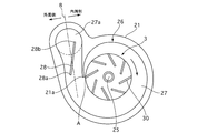
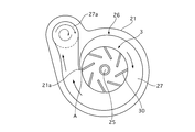
- FIG. FIG. 3 is a view showing a state where a pump cover of the electric water pump according to the first embodiment is removed. It is a figure which shows the flow of the cooling water in a volute room when a baffle plate is not provided.
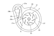
- FIG. 3 is a diagram showing the flow of cooling water in the volute chamber when the current plate of Example 1 is provided.
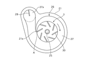
- FIG. 6 is a view showing a state where a pump cover of the electric water pump according to the second embodiment is removed.
- the electric water pump 1 of the first embodiment is a cooling pump that uses a cooling medium (cooling water) as a working fluid and is incorporated in a circulation circuit connected to a heat exchanger (radiator). Engine), a driving motor, an inverter, and the like.
- FIG. 1 is a perspective view of the electric water pump 1.
- the electric water pump 1 is accommodated in the pump housing 2.
- the pump housing 2 includes a pump body 21 and a pump cover 22.
- the pump cover 22 is formed with a suction port 23 and a discharge port 24.
- An impeller 3 having a plurality of wings 30 rotates inside the electric water pump 1, and by rotating the impeller 3, cooling water is sucked from the suction port 23 and cooled from the discharge port 24. Discharge water.
- FIG. 1 is a perspective view of the electric water pump 1.
- the electric water pump 1 is accommodated in the pump housing 2.
- the pump housing 2 includes a pump body 21 and a pump cover 22.
- the pump cover 22 is formed with a su
- the impeller 3 is accommodated in a space (impeller accommodating portion 26) formed inside by the pump body 21 and the pump cover 22.
- the impeller 3 is rotatably provided on a rotary shaft 25 fixed to the pump body 21.
- a volute chamber 27 having a spiral groove is provided on the outer periphery of the impeller accommodating portion 26.
- the volute chamber 27 is formed in a spiral shape in the same direction as the rotation direction of the impeller 3 (clockwise in FIG. 2) starting from the point A in FIG.
- the opposite side of the impeller 3 in the rotation direction of the volute chamber 27 is referred to as the upstream side, and the rotation direction side is referred to as the downstream side.
- the discharge port connecting portion 27a at the most downstream portion of the volute chamber 27 is connected to the discharge port 24 of the pump cover. Further, the side surface of the discharge port connecting portion 27a is formed in an arc shape.
- the pump body 21 is formed with a tongue portion 21a that separates the upstream side and the downstream side of the volute chamber 27 from each other.
- a rectifying plate 28 is formed in the volute chamber 27. The rectifying plate 28 is provided so as to divide a part of the volute chamber 27 into two flow paths. The height of the current plate 28 is formed to be the same as the height direction of the volute chamber 27.
- the rectifying plate 28 is provided on the downstream side of the volute chamber 27, and the upstream end portion 28a is provided on the downstream side of the end portion of the tongue portion 21a.
- the downstream end portion 28b of the rectifying plate 28 extends to the discharge port connecting portion 27a, but does not contact the side surface of the discharge port connecting portion 27a.
- the upstream end portion 28a of the rectifying plate 28 is located on the outer peripheral side of the intermediate point in the width direction of the volute chamber 27 (the point on the line B), and the downstream end portion 28b is the intermediate point in the width direction of the volute chamber 27 ( It is formed so as to be located on the inner peripheral side with respect to the point on the line B).
- FIG. 3 is a diagram showing the flow of cooling water in the volute chamber 27 when the rectifying plate 28 is not provided.
- the cooling water sucked from the suction port 23 by the rotation of the impeller 3 is sent to the volute chamber 27 by centrifugal force and flows in the same direction as the rotation direction of the impeller 3.
- the flow rate on the outer peripheral side of the volute chamber 27 is faster than the flow rate on the inner peripheral side. Therefore, in the discharge port connecting portion 27a of the volute chamber 27, a swirl flow swirling from the outer peripheral side toward the inner peripheral side, and the cooling water flows along the wall surface of the discharge port 24 and the pipe connected to the discharge port 24. It will be.
- FIG. 4 is a diagram illustrating the flow of cooling water in the volute chamber 27 when the rectifying plate 28 of the first embodiment is provided.
- the upstream end 28a is positioned on the outer peripheral side of the intermediate point in the width direction of the volute chamber 27, and the downstream end 28b is on the inner peripheral side of the intermediate point in the width direction of the volute chamber 27. Is located.
- the flow on the outer peripheral side of the volute chamber 27 enters from the narrow inlet and exits from the wide outlet, and the flow velocity decreases.
- the flow on the outer peripheral side of the volute chamber 27 enters from a wide inlet and exits from a narrow outlet, and the flow velocity increases. Therefore, in the discharge port coupling portion 27a of the volute chamber 27, the flow on the outer peripheral side and the flow on the inner peripheral side of the cooling water cancel each other, and the generation of the swirling flow can be suppressed.
- the friction loss generated between the discharge port 24 and the wall surface of the pipe connected to the discharge port 24 can be reduced, and the temperature rise of the cooling water can be suppressed, so that the pump efficiency can be improved.
- the current plate 28 is provided on the downstream side of the end portion of the tongue portion 21a of the volute chamber 27. Thereby, the length of the rectifying plate 28 can be shortened, the flow path resistance can be reduced, and the pump efficiency can be improved.
- the upstream end 28a of the rectifying plate 28 is positioned on the outer peripheral side of the intermediate point in the width direction of the volute chamber 27, the downstream end of the rectifying plate 28 is 28b, and the intermediate in the width direction of the volute chamber 27. It was located on the inner circumference side of the point. Therefore, the flow velocity on the outer peripheral side of the volute chamber 27 can be reduced by the rectifying plate 28, and at the discharge port connecting portion 27a of the volute chamber 27, the flow on the outer peripheral side and the flow on the inner peripheral side cancel each other. Generation of swirling flow can be suppressed.
- FIG. 5 is a view of the electric water pump 1 with the pump cover 22 removed.
- a rectifying plate 28 extending from the side surface of the discharge port connecting portion 27a into the volute chamber 27 was provided. Thereby, the flow which goes to the inner peripheral side from the outer peripheral side can be inhibited in the discharge port connection part 27a, and generation
- the rectifying plate 28 is formed so as to extend into the volute chamber 27 from the side surface of the discharge port connecting portion 27a of the volute chamber 27. Therefore, it is possible to inhibit the flow from the outer peripheral side to the inner peripheral side in the discharge port connecting portion 27a, and it is possible to suppress the generation of the swirling flow.
Landscapes
- Engineering & Computer Science (AREA)
- Mechanical Engineering (AREA)
- General Engineering & Computer Science (AREA)
- Structures Of Non-Positive Displacement Pumps (AREA)
Abstract
Description
本発明は、上記問題に着目されたもので、その目的とするところは、効率を高めることができるウォータポンプを提供することである。
実施例1の電動ウォータポンプ1は、作動流体として冷却媒体(冷却水)を用い、熱交換機(ラジエータ)に接続された循環回路中に組み込まれる冷却用ポンプであり、例えばハイブリッド自動車においてエンジン(内燃機関)や駆動用モータ、インバータ等に冷却水を供給するウォータポンプである。
図1は、電動ウォータポンプ1の斜視図である。電動ウォータポンプ1は、ポンプハウジング2内に収容されている。ポンプハウジング2は、ポンプボディ21とポンプカバー22とから構成されている。ポンプカバー22には、吸入口23と吐出口24とが形成されている。電動ウォータポンプ1の内部には、複数の羽30を有するインペラ3が回転するようになっており、インペラ3が回転することで、吸入口23から冷却水を吸入して、吐出口24から冷却水を吐出する。
図2は、電動ウォータポンプ1のポンプカバー22を取り外した状態の図である。インペラ3は、ポンプボディ21とポンプカバー22とによって内部に形成される空間(インペラ収容部26)に収容されている。インペラ3は、ポンプボディ21に固定された回転軸25に、回転自在に設けられている。インペラ収容部26の外周部には、渦巻き状に溝が形成されたボリュート室27が設けられている。ボリュート室27は、図2のA点を始点として、インペラ3の回転方向(図2において右回り)と同方向の渦巻き状に形成されている。なお、以下では、ボリュート室27のインペラ3の回転方向反対側を上流側、回転方向側を下流側と称する。ボリュート室27の最下流部の吐出口連結部27aは、ポンプカバーの吐出口24に接続する。また、吐出口連結部27aの側面は、円弧状に形成されている。ポンプボディ21には、ボリュート室27の上流側と下流側とを区切る舌部21aが形成されている。
ボリュート室27内には、整流板28が形成されている。整流板28は、ボリュート室27の一部を2つの流路に分断するように設けられている。整流板28の高さは、ボリュート室27の高さ方向と同じ高さに形成されている。整流板28は、ボリュート室27の下流側に設けられており、上流側端部28aは、舌部21aの端部よりも下流側に設けられている。整流板28の下流側端部28bは、吐出口連結部27aまで伸びているが、吐出口連結部27aの側面には当接しないようになっている。整流板28の上流側端部28aは、ボリュート室27の幅方向中間点(線B上の点)よりも外周側に位置し、下流側端部28bは、ボリュート室27の幅方向中間点(線B上の点)よりも内周側に位置するように形成されている。
図3は、整流板28を設けなかったときのボリュート室27内の冷却水の流れを示す図である。インペラ3の回転により吸入口23から吸入された冷却水は、遠心力によってボリュート室27に送られ、インペラ3の回転方向と同じ方向に流れる。このとき、ボリュート室27の外周側の流速は、内周側の流速よりも速くなる。そのため、ボリュート室27の吐出口連結部27aでは、外周側から内周側に向かって旋回する旋回流となり、冷却水は、吐出口24および該吐出口24に連結する配管の壁面に沿って流れることとなる。そのため、壁面との間で摩擦損失が生じ、また摩擦により冷却水の温度が高くなり冷却効率が低下する。
そこで、実施例1では、ボリュート室27に整流板28を設け、該ボリュート室27の外周側の冷却水の流速を低下させるようにした。図4は、実施例1の整流板28を設けたときのボリュート室27内の冷却水の流れを示す図である。実施例1の整流板28は、上流側端部28aがボリュート室27の幅方向中間点よりも外周側に位置し、下流側端部28bがボリュート室27の幅方向中間点よりも内周側に位置している。つまり、ボリュート室27の外周側の流れは、狭い入口から入って広い出口から出ることとなって、流速は減少する。一方、ボリュート室27の外周側の流れは、広い入口から入って狭い出口から出ることとなって、流速は増加する。そのため、ボリュート室27の吐出口連結部27aでは、冷却水の外周側の流れと内周側の流れとが打ち消し合って、旋回流の発生を抑制することができる。これにより、吐出口24および該吐出口24に連結する配管の壁面との間で生じる摩擦損失を低減し、また冷却水の温度上昇を抑制することができるため、ポンプ効率を向上させることができる。
また、整流板28を、ボリュート室27の舌部21aの端部よりも下流側に設けた。これにより、整流板28の長さを短くし、流路抵抗を小さくすることができ、ポンプ効率を向上させることができる。
(1) 吸入口23と吐出口24とが形成されたポンプハウジング2と、ポンプハウジング2のインペラ収容部26に回転可能に配置され、吸入口23から冷却水を吸入して吐出口24から吐出するインペラ3と、インペラ収容部26の外周部に渦巻き状に形成され、下流側が吐出口24につながるボリュート室27と、ボリュート室27の下流側と上流側とを区切る舌部21aと、ボリュート室27の舌部21aの端部よりも下流側に設けられ、ボリュート室27の外周側の冷却水の流速を低下させる整流板28と、を備えた。
よって、ボリュート室27の吐出口連結部27aでは、冷却水の外周側の流れと内周側の流れとが打ち消し合い、旋回流の発生を抑制することができる。
(2) 整流板28の上流側端部28aは、ボリュート室27の幅方向の中間点よりも外周側に位置し、整流板28の下流側端部は28b、ボリュート室27の幅方向の中間点よりも内周側に位置するようにした。
よって、整流板28によってボリュート室27の外周側の流速を低下させることができ、ボリュート室27の吐出口連結部27aでは、冷却水の外周側の流れと内周側の流れとが打ち消し合い、旋回流の発生を抑制することができる。
実施例2の電動ウォータポンプ1について説明する。実施例1と同じ構成については、同一の符号を付して説明を省略する。図5は、電動ウォータポンプ1のポンプカバー22を取り外した状態の図である。
吐出口連結部27aの側面からボリュート室27内に延びる整流板28を設けた。これにより、吐出口連結部27aにおいて外周側から内周側に向かう流れを阻害することができ、旋回流の発生を抑制することができる。
[効果]
(3) 整流板28を、ボリュート室27の吐出口連結部27aの側面からボリュート室27内に延びるように形成した。
よって、吐出口連結部27aにおいて外周側から内周側に向かう流れを阻害することができ、旋回流の発生を抑制することができる。
以上、本発明を実施例1および実施例2に基づいて説明してきたが、各発明の具体的な構成は実施例1および実施例2に限定されるものではなく、発明の要旨を逸脱しない範囲の設計変更等があっても、本発明に含まれる。
3 インペラ
21a 舌部
23 吸入口
24 吐出口
26 インペラ収容部
27 ボリュート室
28 整流板
Claims (3)
- 吸入口と吐出口とが形成されたポンプハウジングと、
該ポンプハウジングのインペラ収容部に回転可能に配置され、前記吸入口から冷却水を吸入して前記吐出口から吐出するインペラと、
前記インペラ収容部の外周部に渦巻き状に形成され、下流側が前記吐出口につながるボリュート室と、
該ボリュート室の下流側と上流側とを区切る舌部と、
前記ボリュート室の前記舌部の端部よりも下流側に設けられ、前記ボリュート室の外周側の冷却水の流速を低下させる整流板と、
を備えたことを特徴とするウォータポンプ。 - 請求項1に記載のウォータポンプにおいて、
前記整流板の上流側端部は、前記ボリュート室の幅方向の中間点よりも外周側に位置し、前記整流板の下流側端部は、前記ボリュート室の幅方向の中間点よりも内周側に位置することを特徴とするウォータポンプ。 - 請求項1に記載のウォータポンプにおいて、
前記整流板は、前記ボリュート室の最下流部の側面からボリュート室内に延びるように形成したことを特徴とするウォータポンプ。
Priority Applications (3)
| Application Number | Priority Date | Filing Date | Title |
|---|---|---|---|
| DE112014000220.8T DE112014000220T5 (de) | 2013-09-24 | 2014-07-14 | Wasserpumpe |
| CN201480002182.4A CN104718381A (zh) | 2013-09-24 | 2014-07-14 | 水泵 |
| US14/430,349 US20160258444A1 (en) | 2013-09-24 | 2014-07-14 | Water Pump |
Applications Claiming Priority (2)
| Application Number | Priority Date | Filing Date | Title |
|---|---|---|---|
| JP2013-196493 | 2013-09-24 | ||
| JP2013196493A JP2015063900A (ja) | 2013-09-24 | 2013-09-24 | 電動ウォータポンプ |
Publications (1)
| Publication Number | Publication Date |
|---|---|
| WO2015045569A1 true WO2015045569A1 (ja) | 2015-04-02 |
Family
ID=52742726
Family Applications (1)
| Application Number | Title | Priority Date | Filing Date |
|---|---|---|---|
| PCT/JP2014/068661 Ceased WO2015045569A1 (ja) | 2013-09-24 | 2014-07-14 | ウォータポンプ |
Country Status (5)
| Country | Link |
|---|---|
| US (1) | US20160258444A1 (ja) |
| JP (1) | JP2015063900A (ja) |
| CN (1) | CN104718381A (ja) |
| DE (1) | DE112014000220T5 (ja) |
| WO (1) | WO2015045569A1 (ja) |
Cited By (1)
| Publication number | Priority date | Publication date | Assignee | Title |
|---|---|---|---|---|
| CN117722393A (zh) * | 2024-01-30 | 2024-03-19 | 扬州大学 | 一种离心泵隔舌结构 |
Families Citing this family (3)
| Publication number | Priority date | Publication date | Assignee | Title |
|---|---|---|---|---|
| CN112443487A (zh) * | 2019-09-03 | 2021-03-05 | 广东美的白色家电技术创新中心有限公司 | 一种具有加热装置的泵及一种清洁装置 |
| WO2021042613A1 (zh) | 2019-09-03 | 2021-03-11 | 广东美的白色家电技术创新中心有限公司 | 加热泵及具有其的清洁装置 |
| CN118066147B (zh) * | 2024-02-18 | 2025-11-21 | 浙江益鸿能源科技有限公司 | 一种增流降阻水泵 |
Citations (6)
| Publication number | Priority date | Publication date | Assignee | Title |
|---|---|---|---|---|
| US2454390A (en) * | 1944-08-23 | 1948-11-23 | Duriron Co | Centrifugal pump |
| JPS5927198U (ja) * | 1982-07-09 | 1984-02-20 | 株式会社ノーリツ | うず巻きポンプ |
| JPH0689753B2 (ja) * | 1984-04-18 | 1994-11-14 | ウオアマン・インタ−ナショナル・リミテッド | 遠心スラリポンプのケ−シング |
| JP3662633B2 (ja) * | 1995-06-30 | 2005-06-22 | 株式会社川本製作所 | 水中ポンプ |
| JP2008121430A (ja) * | 2006-11-08 | 2008-05-29 | Aisin Seiki Co Ltd | ウォータポンプ |
| JP2013057277A (ja) * | 2011-09-07 | 2013-03-28 | Honda Motor Co Ltd | 遠心ポンプ |
Family Cites Families (5)
| Publication number | Priority date | Publication date | Assignee | Title |
|---|---|---|---|---|
| GB555308A (en) * | 1941-03-08 | 1943-08-17 | Alfred Buechi | Improvements in or relating to diffuser devices for centrifugal pumps or blowers |
| JPH04203294A (ja) * | 1990-11-29 | 1992-07-23 | Atsushi Tsuchida | インデューサ付き遠心ポンプ |
| WO2008129953A1 (ja) * | 2007-04-20 | 2008-10-30 | Mitsubishi Heavy Industries, Ltd. | 遠心圧縮機 |
| JP5727881B2 (ja) * | 2011-06-30 | 2015-06-03 | 株式会社荏原製作所 | 輪切形多段ポンプ |
| CN202628620U (zh) * | 2012-05-15 | 2012-12-26 | 张家港市恩达泵业有限公司 | 一种卧式泵的涡室结构 |
-
2013
- 2013-09-24 JP JP2013196493A patent/JP2015063900A/ja active Pending
-
2014
- 2014-07-14 DE DE112014000220.8T patent/DE112014000220T5/de not_active Withdrawn
- 2014-07-14 WO PCT/JP2014/068661 patent/WO2015045569A1/ja not_active Ceased
- 2014-07-14 CN CN201480002182.4A patent/CN104718381A/zh active Pending
- 2014-07-14 US US14/430,349 patent/US20160258444A1/en not_active Abandoned
Patent Citations (6)
| Publication number | Priority date | Publication date | Assignee | Title |
|---|---|---|---|---|
| US2454390A (en) * | 1944-08-23 | 1948-11-23 | Duriron Co | Centrifugal pump |
| JPS5927198U (ja) * | 1982-07-09 | 1984-02-20 | 株式会社ノーリツ | うず巻きポンプ |
| JPH0689753B2 (ja) * | 1984-04-18 | 1994-11-14 | ウオアマン・インタ−ナショナル・リミテッド | 遠心スラリポンプのケ−シング |
| JP3662633B2 (ja) * | 1995-06-30 | 2005-06-22 | 株式会社川本製作所 | 水中ポンプ |
| JP2008121430A (ja) * | 2006-11-08 | 2008-05-29 | Aisin Seiki Co Ltd | ウォータポンプ |
| JP2013057277A (ja) * | 2011-09-07 | 2013-03-28 | Honda Motor Co Ltd | 遠心ポンプ |
Cited By (1)
| Publication number | Priority date | Publication date | Assignee | Title |
|---|---|---|---|---|
| CN117722393A (zh) * | 2024-01-30 | 2024-03-19 | 扬州大学 | 一种离心泵隔舌结构 |
Also Published As
| Publication number | Publication date |
|---|---|
| JP2015063900A (ja) | 2015-04-09 |
| DE112014000220T5 (de) | 2015-08-06 |
| US20160258444A1 (en) | 2016-09-08 |
| CN104718381A (zh) | 2015-06-17 |
Similar Documents
| Publication | Publication Date | Title |
|---|---|---|
| JP6190144B2 (ja) | 冷却チャンネルを有するモータユニット | |
| EP3251880B1 (en) | Electric machine having a tangential architecture with improved air cooling | |
| CN108138801B (zh) | 锅炉泵 | |
| JP4872456B2 (ja) | ポンプ及び液体供給装置 | |
| JP2024531544A5 (ja) | ||
| CN106062380B (zh) | 送风装置 | |
| JP6583770B2 (ja) | 遠心式送風機 | |
| KR20120076039A (ko) | 축류팬 및 이를 포함하는 공기조화기의 실외기 | |
| US10443606B2 (en) | Side-channel blower for an internal combustion engine | |
| JP2015063900A (ja) | 電動ウォータポンプ | |
| CN204669160U (zh) | 电机 | |
| JP2011140917A (ja) | 両吸込ポンプ | |
| JP5984133B2 (ja) | 渦巻きポンプ | |
| KR20150133408A (ko) | 양흡입 송풍팬의 구동모터 설치구조 | |
| JP2016166558A (ja) | 送風機 | |
| JP6128525B2 (ja) | 渦流ファン | |
| CN106533033A (zh) | 外转子电机散热结构及外转子电机 | |
| JP2009144531A (ja) | 遠心ポンプ用羽根車及び遠心ポンプ | |
| JP6681788B2 (ja) | モータ一体型流体機械 | |
| JP2006144735A (ja) | ウォータポンプ | |
| JP7588293B2 (ja) | ポンプ | |
| CN111503053A (zh) | 泵 | |
| JP6700893B2 (ja) | 羽根車、回転機械 | |
| JP6104402B2 (ja) | 流体機械 | |
| JP6283928B2 (ja) | インペラ及びカスケードポンプ |
Legal Events
| Date | Code | Title | Description |
|---|---|---|---|
| WWE | Wipo information: entry into national phase |
Ref document number: 14430349 Country of ref document: US |
|
| WWE | Wipo information: entry into national phase |
Ref document number: 112014000220 Country of ref document: DE Ref document number: 1120140002208 Country of ref document: DE |
|
| 121 | Ep: the epo has been informed by wipo that ep was designated in this application |
Ref document number: 14847034 Country of ref document: EP Kind code of ref document: A1 |
|
| 122 | Ep: pct application non-entry in european phase |
Ref document number: 14847034 Country of ref document: EP Kind code of ref document: A1 |