WO2015045443A1 - 電子顕微鏡 - Google Patents
電子顕微鏡 Download PDFInfo
- Publication number
- WO2015045443A1 WO2015045443A1 PCT/JP2014/056823 JP2014056823W WO2015045443A1 WO 2015045443 A1 WO2015045443 A1 WO 2015045443A1 JP 2014056823 W JP2014056823 W JP 2014056823W WO 2015045443 A1 WO2015045443 A1 WO 2015045443A1
- Authority
- WO
- WIPO (PCT)
- Prior art keywords
- image
- electron microscope
- sample
- gas
- electron
- Prior art date
- Legal status (The legal status is an assumption and is not a legal conclusion. Google has not performed a legal analysis and makes no representation as to the accuracy of the status listed.)
- Ceased
Links
Images




Classifications
-
- H—ELECTRICITY
- H01—ELECTRIC ELEMENTS
- H01J—ELECTRIC DISCHARGE TUBES OR DISCHARGE LAMPS
- H01J37/00—Discharge tubes with provision for introducing objects or material to be exposed to the discharge, e.g. for the purpose of examination or processing thereof
- H01J37/02—Details
- H01J37/22—Optical, image processing or photographic arrangements associated with the tube
- H01J37/222—Image processing arrangements associated with the tube
-
- H—ELECTRICITY
- H01—ELECTRIC ELEMENTS
- H01J—ELECTRIC DISCHARGE TUBES OR DISCHARGE LAMPS
- H01J37/00—Discharge tubes with provision for introducing objects or material to be exposed to the discharge, e.g. for the purpose of examination or processing thereof
- H01J37/02—Details
- H01J37/22—Optical, image processing or photographic arrangements associated with the tube
-
- H—ELECTRICITY
- H01—ELECTRIC ELEMENTS
- H01J—ELECTRIC DISCHARGE TUBES OR DISCHARGE LAMPS
- H01J37/00—Discharge tubes with provision for introducing objects or material to be exposed to the discharge, e.g. for the purpose of examination or processing thereof
- H01J37/02—Details
- H01J37/244—Detectors; Associated components or circuits therefor
-
- H—ELECTRICITY
- H01—ELECTRIC ELEMENTS
- H01J—ELECTRIC DISCHARGE TUBES OR DISCHARGE LAMPS
- H01J37/00—Discharge tubes with provision for introducing objects or material to be exposed to the discharge, e.g. for the purpose of examination or processing thereof
- H01J37/26—Electron or ion microscopes; Electron or ion diffraction tubes
-
- H—ELECTRICITY
- H01—ELECTRIC ELEMENTS
- H01J—ELECTRIC DISCHARGE TUBES OR DISCHARGE LAMPS
- H01J37/00—Discharge tubes with provision for introducing objects or material to be exposed to the discharge, e.g. for the purpose of examination or processing thereof
- H01J37/26—Electron or ion microscopes; Electron or ion diffraction tubes
- H01J37/28—Electron or ion microscopes; Electron or ion diffraction tubes with scanning beams
-
- H—ELECTRICITY
- H01—ELECTRIC ELEMENTS
- H01J—ELECTRIC DISCHARGE TUBES OR DISCHARGE LAMPS
- H01J37/00—Discharge tubes with provision for introducing objects or material to be exposed to the discharge, e.g. for the purpose of examination or processing thereof
- H01J37/26—Electron or ion microscopes; Electron or ion diffraction tubes
- H01J37/285—Emission microscopes, e.g. field-emission microscopes
-
- H—ELECTRICITY
- H01—ELECTRIC ELEMENTS
- H01J—ELECTRIC DISCHARGE TUBES OR DISCHARGE LAMPS
- H01J2237/00—Discharge tubes exposing object to beam, e.g. for analysis treatment, etching, imaging
- H01J2237/006—Details of gas supplies, e.g. in an ion source, to a beam line, to a specimen or to a workpiece
Definitions
- the present invention relates to an electron microscope.
- in-situ observation is sometimes performed in which a reaction process between a sample in a gas atmosphere and the gas is dynamically observed in situ.
- in-situ observation when the catalyst is exposed to a gas, noble metal particles move on the carrier and grow particles, and deterioration analysis of the catalyst is performed by observing the particle growth in situ.
- the sample holder includes a sample mounting portion in which an opening for passing an electron beam is formed, a heater wire (sample heating device) stretched across the opening, and the sample mounting portion in the sample chamber ( A diaphragm for isolating from a vacuum) and a gas introduction pipe (gas introduction device) for introducing gas into a sample mounting space formed by the diaphragm.
- the voltage control and the control of the introduced gas are also performed manually.
- the voltage control and the control of the introduced gas are also performed manually.
- An object of the present invention is to provide an electron microscope capable of obtaining a microscopic image of a sample placed in a gas atmosphere by controlling correction of sample drift due to reaction.
- the present invention provides a detector for detecting electrons generated by irradiating a sample with an electron beam from an electron gun, and a microscopic image of the sample based on the output of the detector.
- a gas control device that controls the amount of gas released by the gas introduction device so that the degree of vacuum in the space in which the vessel is installed is continuously kept below a set value.
- moving image observation can be performed by reducing sample drift by in-situ observation of a sample in a gas atmosphere.
- FIG. 1 is a schematic configuration diagram of a scanning fluoroscopic electron microscope according to an embodiment of the present invention.
- the schematic block diagram of the sample holder 53 which concerns on embodiment of this invention.
- the schematic diagram of the division of each room provided in the lens body of the electron microscope which concerns on embodiment of this invention.
- the schematic block diagram of the pressure display part 90 which concerns on embodiment of this invention.
- An example of the display screen of the monitor 39 which concerns on embodiment of this invention.
- An example of the moving image recording screen which concerns on embodiment of this invention.
- a scanning transmission electron microscope (STEM) will be described as an example, but the present invention is an electron including a scanning electron microscope (SEM), a transmission electron microscope (TEM), and a scanning transmission electron microscope. It can be applied not only to a microscope but also to a charged particle beam apparatus.
- FIG. 1 is a schematic configuration diagram of a scanning fluoroscopic electron microscope according to an embodiment of the present invention.
- the electron microscope apparatus shown in this figure includes an electron gun 1, first and second irradiation lens coils 2 and 3, first and second deflection coils (scanning coils) 4 and 5, and an objective lens coil 6.
- a sample holder 53 for holding the sample 70 (see FIG. 3) is disposed on the optical axis.
- the objective lens coil 6 shown in the figure is a strong excitation lens (see FIG. 4), and lenses are formed on the upper side and the lower side of the sample.
- FIG. 2 is a diagram showing an extracted main part related to the present invention in the electron microscope apparatus according to the embodiment of the present invention.
- the electron microscope section according to the present embodiment includes an electron gun 1, a converging electron lens formed by irradiation lens coils 2 and 3, and an electron beam generated by the electron gun 1 as a sample 70 (FIG. 3).
- Reference) Deflection coils (scanning coils) 4 and 5 as a scanning device to be scanned above, a sample holder 53 holding a sample 70, and an electron beam from the electron gun 1 are generated when the sample 70 is irradiated.
- a detector for detecting electrons (secondary electron detector 51, backscattered electron detector 55, dark field image detector 50 and bright field image detector 49), computer 80, and detectors 51, 55, 50, 49
- a monitor 39 for displaying a microscopic image of the sample 70 based on the output and a pressure display unit 90 for displaying the degree of vacuum of each part in the lens body are provided.
- the computer 80 records a part of the hardware shown in FIG. 1 such as the microprocessor 35, HDD 36, monitor controller 38, RAM 45, ROM 46, and image capture interface 48, and a microscope image displayed on the monitor 39.
- a recording control device 95 is installed.
- FIG. 3 is a schematic configuration diagram of the sample holder 53 according to the embodiment of the present invention.
- the sample holder 53 includes a heater (heating device) 64, a vacuum gauge 65, and a gas introduction device 60.
- the heater 64 is composed of a wire that spans a pair of lead wires connected to a power source (not shown), and the sample 70 is attached and held on the wire. That is, the heater 64 also functions as a sample holder.
- a temperature sensor is attached to the heater 64 so that the temperature of the sample 70 can be detected.
- the output of the temperature sensor (that is, the sample temperature) is output to the computer 80 and displayed on the monitor 39 as necessary.
- the output of the heater 64 is controlled based on a control signal output to the heater 64 from a heater control device 83 mounted in the computer 80.
- the vacuum gauge 65 is for detecting the degree of vacuum (pressure) in the vicinity of the sample 70 and is installed in the sample holder 53.
- the vacuum gauge 65 is attached to the sample holder 53 so as to be located within 1 mm from the sample 70 in the example shown in the figure, but may be installed independently from the sample holder 53.
- the output of the vacuum gauge 65 (pressure in the vicinity of the sample 70) is output to the computer 80, and is displayed on the pressure display unit 90 (see FIG. 2), or control of the gas discharge amount by the gas introduction device 60 (described later). It is used for.
- FIG. 4 is a schematic diagram of compartments of each room provided in the body of the electron microscope according to the embodiment of the present invention.
- the body of the electron microscope according to the present embodiment can be classified into an electron gun chamber 71, a first intermediate chamber 72, a second intermediate chamber 73, a third intermediate chamber 74, and a sample chamber 75.
- a first orifice 76 is installed in a partition wall that divides the electron gun chamber 71 and the first intermediate chamber 72.
- a gun valve 78 is installed in a partition wall that divides the first intermediate chamber 72 and the second intermediate chamber 73.
- a second orifice 79 is installed in a partition wall provided in the second intermediate chamber, and a third orifice 84 is installed in a partition partitioning the second intermediate chamber 74 and the third intermediate chamber 75.
- the third intermediate chamber 75 and the sample chamber 76 are partitioned by the upper magnetic pole 85 of the objective lens, and the sample holder 53 is disposed between the upper magnetic pole 85 and the lower magnetic pole 86 of the objective lens
- a vacuum pump (ion pump) 87 a is connected to the electron gun chamber 71, a vacuum pump (ion pump) 87 b is connected to the first intermediate chamber 72, and a vacuum pump (ion ion) is connected to the second intermediate chamber 73.
- Pump) 87c is connected.
- the same vacuum pump (the turbo molecular pump 88 and the dry pump 89) is independent in the third intermediate chamber 74, the space formed between the upper magnetic pole 85 and the lower magnetic pole 86, and the space below the lower magnetic pole 87. Connected through a route.
- a secondary electron detector 51 to which a predetermined voltage (extraction voltage) is applied when detecting secondary electrons generated by the electron beam from the electron gun 1 is installed.
- Application of the voltage of the secondary electron detector 51 is controlled based on a control signal output to the secondary electron detector 51 from the detector control device 82 mounted in the computer 80.
- a vacuum gauge 77 is installed at the suction port of the turbo molecular pump 88, and the detection value of the vacuum gauge 77 is output to the computer 80.
- FIG. 5 is a schematic configuration diagram of the pressure display unit 90 according to the embodiment of the present invention.
- the pressure display unit 90 shown in this figure includes a first display unit 91 that displays a detection value of a vacuum gauge 77 installed in the vicinity of the suction port of the turbo molecular pump 88, and a vacuum gauge installed in the sample holder 53. It has the 2nd display part 92 on which 65 detected values are displayed.
- the pressure at the suction port of the turbo molecular pump 88 is 0.034 [Pa], while the pressure near the sample 70 is maintained at 1.0 [Pa]. .
- the gas introducing device 60 is for discharging gas to the sample 70 irradiated with the electron beam generated by the electron gun 1.
- the gas introduction device 60 is connected to a gas cylinder (not shown) and has a gas nozzle 61 having a tip of an injection port 63 opened in the sample holder 53, and an adjustment for adjusting the amount of gas discharged from the injection port 63.
- a valve 62 is provided.
- the injection port 63 is directed to the heater 64, and the gas from the injection port 63 is released to the sample 70 on the wire in the heater 64.
- the adjustment valve 62 is an electromagnetic valve, and the opening degree of the adjustment valve 62 is controlled based on a control signal output from the gas control device 81.
- the gas control device 81 performs gas treatment so that the degree of vacuum in the third intermediate chamber 74 in which the secondary electron detector 51 is installed is continuously maintained below the set value P1. This is for controlling the gas introduction amount (discharge amount) by the introduction device 60.
- the gas control device 81 is mounted in the computer 80.
- the output of the vacuum gauge 65 is input to the gas control device 81, and the gas control device 81 inputs a gas introduction amount (discharge amount) into the sample holder 53 based on the degree of vacuum input from the vacuum gauge 65. Is adjusted.
- the gas control device 81 holds the adjustment valve 62 at a predetermined opening and receives the input from the vacuum gauge 65.
- the pressure value is equal to or greater than the set value P1
- a process for closing the adjustment valve 62 and stopping the gas introduction device 60 from releasing the gas to the sample 70 is executed.
- the set value P1 relating to the control of the gas introduction amount is determined based on the value of the voltage (drawing voltage) applied to the secondary electron detector 51 and the type of gas introduced by the gas introduction device 60. It is set to a value at which no discharge occurs when the extraction voltage is applied to the secondary electron detector 51.
- FIG. 6 is an example of a display screen of the monitor 39 according to the embodiment of the present invention.
- the screen shown in this figure includes an image display unit 101 on which electron microscope images 111 and 112 are displayed, an image control unit 102 for controlling the images 111 and 112 displayed on the image display unit 101, and mainly an electron microscope.
- the image display unit 101 displays one or more electron microscope images for each window.
- the number of windows displayed on the image display unit 101 can be freely increased or decreased via the main control unit 103.
- two windows (images) 111 and 112 are displayed.
- the image control unit 102 can control an image related to a window 111 or 112 displayed on the image display unit 101 that is selected by the mouse 57 or the like (hereinafter may be referred to as a “selected window”). it can.
- FIG. 10 is an enlarged view of the image control unit 102. As shown in this figure, the image control unit 102 includes a single button 121, a secondary electronic image button 122, a bright field image button 123, a dark field image button 124, a reflected electronic image button 125, and a color button 126.
- Overlay button 131 Overlay button 131, upper image pull-down menu 132, lower image pull-down menu 133, color button 134, color button 135, transmittance input unit 136, time button 141, vacuum degree button 142, sample A temperature button 143, a time button 144, and a recording button 151 are provided.
- the selected button is displayed with “black paint”, and the unselected button is displayed with “white paint”.
- the secondary electron image detected by the secondary electron detector 51 at that time is selected as a real-time moving image. Displayed in the window.
- the bright field image button 123 is pressed, a bright field image is displayed in the selection window
- the dark field image button 124 is pressed, a dark field image is displayed in the selection window
- the reflected electron image button 125 is pressed, the selection window is displayed. A reflected electron image is displayed. Only one of these buttons 122, 123, 124, and 125 can be pressed. When a button other than the selected button is pressed, the selection of the button that has been selected is canceled. .
- the image in the selection window can be switched. Since the secondary electron image, the bright field image, the dark field image, and the reflected electron image can be alternately displayed in real time as desired by the operator, for example, the movement of the particles related to the sample 70 can be easily grasped.
- the image displayed in the selection window changes from grayscale display to pseudo color display.
- the pseudo color display corresponds to, for example, a display in which an image is displayed with a single chromatic color of green and light instead of black and white.
- the color button 126 can be selected together with the other buttons 122, 123, 124 and 125.
- the selection is canceled and the display image returns to the gray scale display.
- the shooting time of the image is displayed on the image in the selected window.
- the degree of vacuum button 142 is pressed, the degree of vacuum (pressure) of the vacuum gauge 65 related to the photographing time of the image is displayed on the image in the selection window.
- the sample temperature button 143 is pressed, the sample temperature related to the photographing time of the image is displayed on the image in the selection window.
- the time button 144 is pressed, an elapsed time from the time when the observation of the sample 70 is started to the time when the image is captured is displayed on the image in the selection window.
- the observation start time of the sample 70 is designated by the operator via the main control unit 103.
- the time, the degree of vacuum, the sample temperature, and the time are displayed on the image in the window, but these may be displayed at other places on the screen. Furthermore, if it is the information which concerns on an image, it is information other than time, a vacuum degree, sample temperature, and time (for example, the total amount of energy added to the sample 70 with the heater 64 during observation, and observation conditions of an electron microscope) Needless to say, the electron acceleration voltage, magnification, scale bar, and the like may be displayed.
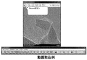
- the recording button 151 is a button for storing (recording) an image (moving image) displayed in the selection window in a storage device (for example, HDD or ROM) in the computer 80.
- a recording start signal is output to the recording control device 95, and recording of a moving image in the selection window is started.
- a recording stop signal is output to the recording control device 95 and recording is stopped.
- the recording is started by pressing the recording button 151.
- the recording control device 95 may be set so as to record automatically.
- the recorded moving image may be configured to be displayed on the image display unit 101 after the observation is completed. In this case, the recorded moving image can also be displayed via the image display unit 101 and the image control unit 102.
- FIG. 11 is a diagram illustrating an example of the image display unit 101 when a secondary electron image is displayed in the window 111 and a bright field image is displayed in the window 112.
- the images displayed in the windows 111 and 112 are synchronized and are created based on outputs detected at the same time by the detectors 51, 55, 49, and 50.
- the vacuum degree button 142, the sample temperature button 143, and the time button 144 are pressed for each window 11, 112, and the degree of vacuum, the sample temperature, and the time are displayed on the images in the windows 11, 112. Is displayed.
- a three-dimensional change in the sample can be observed. For example, among the particles related to the sample 70, those present on the surface of the sample 70 move. Thus, it can be observed that the sample sinks from the sample surface into the sample.
- the surface and the inside of the sample 70 can be observed simultaneously. Accordingly, for example, if it can be confirmed that particles that existed on the surface of the sample 70 on the secondary electron image at a certain time have disappeared from the secondary electron image but still exist in the bright field image, the sample 70 can be confirmed. It can be easily confirmed that the particles existing on the surface of the sample have moved from the sample surface to the inside of the sample.
- FIG. 12 is a diagram showing an example in which six windows 111, 112, and 113 are displayed on the image display unit 101 at the same time.
- a dark field image is displayed in the added window 113.
- the surface, inside, and back surface of the sample 70 can be observed simultaneously. It is possible to easily grasp whether it is located on the front surface, inside, or back surface.
- a reflected electron image may be displayed on the screen display unit 101 by adding a window or instead of another image. Since the reflected electron image has the surface and the inside of the sample, an image in which the secondary electron image and the dark field image are combined can be acquired.
- FIG. 9 is a diagram showing an example of a case where a plurality of types of images are appropriately switched and displayed on one window.
- Selection of an image to be displayed on the selection window can be performed by pressing a secondary electron image button 122, a bright field image button 123, a dark field image button 124, and a reflected electron image button 125. it can.
- any one of the secondary electron image, the bright field image, the dark field image, and the reflected electron image at the same time can be displayed on the selection window.
- the secondary electron image is switched to the dark field image before the gas introduction, and the secondary electron image is switched to the dark field image after the gas introduction.
- the image type is switched in real time during observation, for example, the particle movement related to the sample 70 can be easily grasped visually.
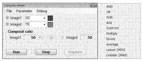
- any two of the secondary electron image, the bright field image, the dark field image, and the reflected electron image are selected. Can be displayed superimposed on each other.
- the upper image pull-down menu 132 is used to select an image to be displayed on the window in which the overlay button 131 is pressed from a secondary electron image, a bright field image, a dark field image, and a reflected electron image.
- the secondary electron image is selected.
- the lower image pull-down menu 133 is used to select an image to be displayed below from the secondary electron image, the bright field image, the dark field image, and the reflected electron image in the window in which the overlay button 131 is pressed.
- a dark field image is selected.
- the single button 121 is used when returning from the superimposed display to the single display when the selection window is superimposed and displayed by the overlay button 131.
- the image displayed in the selection window when returning to the single display is the buttons (secondary electronic image button 122, bright field image button 123, dark field image button 124, reflected electronic image button 125) pressed at the time of return. And the color button 126).
- FIG. 10 relates to a function for tracing particles by reaction, and is a function for displaying the movement of particles as a trajectory.
- FIG. 11 shows an example of trace execution.
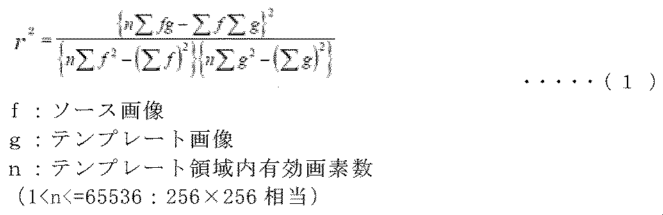
- Trace shows an example of template image search by identifying particles using normalized correlation and image template matching.
- the correlation calculation represented by Expression (1) is performed on all the pixels in the designated area of the source image, and the point at which the matching coefficient (r) is maximum (1.0) is detected as the movement amount. At this time, the degree of coincidence is defined as r multiplied by 100.
- the degree of coincidence increases with respect to fluctuations in brightness and blurring.
- These operations are performed on one area of the source image corresponding to the area of the template image.
- the normalized correlation search according to the present invention, three stages of setup, training, and search are set.
- the template image is cut out from the input image, and the training is performed by using the template image of the normalized correlation search.
- the search a template registered in the training is searched.
- the movement amount calculation a movement position is calculated and calculation is performed with sub-pixel accuracy.
- FIG. 12 shows an example of measuring the area and circumference of the particles.
- the area and circumference may be processed as shown in the figure by performing a two-sided process.
- Fig. 13 shows an example of visual field alignment.
- the movement amount of the particles used in the trace function is corrected by the stage and image shift to adjust the visual field position.
- FIG. 14 shows a control block diagram of the present invention and FIG. 15 shows a control example.
- the horizontal axis represents time
- the vertical axis represents the degree of vacuum
- the degree of vacuum is increased and controlled for a predetermined time, thereby controlling the reaction and reducing the movement of the sample.
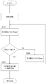
- FIG. 16 shows a vacuum pressure control method.
- the degree of vacuum in the vicinity of the sample can be controlled by opening and closing the gas introduction valve.
- SYMBOLS 1 Electron gun, 2 ... 1st irradiation lens coil, 3 ... 2nd irradiation lens coil, 4 ... 1st deflection coil, 5 ... 2nd deflection coil, 6 ... Objective lens coil, 7 ... 1st electromagnetic sample image movement Coil, 8 ... second electromagnetic sample image moving coil, 9 ... first intermediate lens coil, 10 ... second intermediate lens coil, 11 ... first projection lens coil, 12 ... second projection lens coil, 13-23 ... Excitation power source, 24-34 ... DAC, 35 ... Microprocessor, 36 ... Storage device, 37 ... Calculation device, 38 ... Monitor controller, 39 ... Monitor, 40-41 ... I / F, 42 ...
Landscapes
- Chemical & Material Sciences (AREA)
- Analytical Chemistry (AREA)
- Engineering & Computer Science (AREA)
- Computer Vision & Pattern Recognition (AREA)
- Analysing Materials By The Use Of Radiation (AREA)
Abstract
Description
Claims (7)
- 電子銃からの電子線が試料に照射されることで発生する電子を検出する検出器と、
当該検出器の出力に基づいて前記試料の顕微鏡像を表示する表示装置と
前記試料にガスを放出するためのガス導入装置と、
当該ガス導入装置によるガス放出中に、前記検出器が設置された空間内の真空度が継続的に設定値未満に保持されるように前記ガス導入装置によるガス放出量を制御するガス制御装置と、
を備えることを特徴とする電子顕微鏡。 - 請求項1において、
前記検出器を複数備えており、
前記表示装置は、前記複数の検出器の出力に基づいて複数の顕微鏡像を同時に表示し、
当該複数の顕微鏡像を同時に動画として保存および再生する保存再生装置を備えることを特徴とする電子顕微鏡。 - 請求項2に記載の電子顕微鏡において、
保存した動画像にて、UI上で任意の形状を指定することで、動画ファイル内で画像相関により形状を追尾し、その移動軌跡をデータ化すると共に、動画上に軌跡を表示することを特徴とする電子顕微鏡。 - 請求項2に記載の電子顕微鏡において、
複数検出器画像同時表示にて、任意の形状を指定することで、画像相関により表示画像の形状を追尾し、その移動軌跡をデータ化すると共に、表示画像上に軌跡を表示することを特徴とする電子顕微鏡。 - 請求項2に記載の電子顕微鏡において、
保存した動画像にて、UI上で任意の形状を指定することで、動画ファイル内で画像相関により形状を追尾し、その位置に視野を固定することで、動画上でドリフトのない画像を表示することを特徴とする電子顕微鏡。 - 請求項2に記載の電子顕微鏡において、
電磁的または機械的に視野を移動する視野移動手段を備え、
複数検出器画像同時表示にて、任意の形状を指定することで、画像相関により表示画像の形状を追尾し、前記視野移動手段を用いて、指定した位置に視野移動を行うことで、ドリフトのない画像を表示することを特徴とする電子顕微鏡。 - 請求項2に記載の電子顕微鏡において、
画像内の特徴点の移動を検出することで、各視野において、追尾した形状を抽出して、その抽出した形状に対して、面積、周長等の計測ができることを特徴とする電子顕微鏡。
Priority Applications (3)
| Application Number | Priority Date | Filing Date | Title |
|---|---|---|---|
| CN201480046186.2A CN105830193B (zh) | 2013-09-26 | 2014-03-14 | 电子显微镜 |
| US14/912,549 US9754763B2 (en) | 2013-09-26 | 2014-03-14 | Electron microscope |
| DE112014003791.5T DE112014003791B4 (de) | 2013-09-26 | 2014-03-14 | Elektronenmikroskop |
Applications Claiming Priority (2)
| Application Number | Priority Date | Filing Date | Title |
|---|---|---|---|
| JP2013199129A JP6117070B2 (ja) | 2013-09-26 | 2013-09-26 | 電子顕微鏡 |
| JP2013-199129 | 2013-09-26 |
Publications (1)
| Publication Number | Publication Date |
|---|---|
| WO2015045443A1 true WO2015045443A1 (ja) | 2015-04-02 |
Family
ID=52742603
Family Applications (1)
| Application Number | Title | Priority Date | Filing Date |
|---|---|---|---|
| PCT/JP2014/056823 Ceased WO2015045443A1 (ja) | 2013-09-26 | 2014-03-14 | 電子顕微鏡 |
Country Status (5)
| Country | Link |
|---|---|
| US (1) | US9754763B2 (ja) |
| JP (1) | JP6117070B2 (ja) |
| CN (1) | CN105830193B (ja) |
| DE (1) | DE112014003791B4 (ja) |
| WO (1) | WO2015045443A1 (ja) |
Families Citing this family (2)
| Publication number | Priority date | Publication date | Assignee | Title |
|---|---|---|---|---|
| JP7784347B2 (ja) * | 2022-04-25 | 2025-12-11 | 株式会社Screenホールディングス | 対物レンズユニットおよび顕微鏡 |
| JP2025002248A (ja) | 2023-06-22 | 2025-01-09 | 株式会社日立製作所 | 試料ホルダ、電子顕微鏡システム及び試料観察方法 |
Citations (6)
| Publication number | Priority date | Publication date | Assignee | Title |
|---|---|---|---|---|
| JPH05325859A (ja) * | 1992-05-22 | 1993-12-10 | Hitachi Ltd | 電子線照射装置 |
| JP2002100316A (ja) * | 2000-09-22 | 2002-04-05 | Jeol Ltd | 低真空走査電子顕微鏡 |
| JP2005190864A (ja) * | 2003-12-26 | 2005-07-14 | Hitachi High-Technologies Corp | 電子線装置及び電子線装置用試料ホルダー |
| JP2008047310A (ja) * | 2006-08-11 | 2008-02-28 | Hitachi High-Tech Science Systems Corp | 走査電子顕微鏡 |
| JP2011003426A (ja) * | 2009-06-19 | 2011-01-06 | Jeol Ltd | 電子顕微鏡 |
| JP2011154921A (ja) * | 2010-01-28 | 2011-08-11 | Hitachi High-Technologies Corp | 走査電子顕微鏡 |
Family Cites Families (9)
| Publication number | Priority date | Publication date | Assignee | Title |
|---|---|---|---|---|
| JP2003007247A (ja) * | 2001-06-22 | 2003-01-10 | Seiko Instruments Inc | 走査型電子顕微鏡における画像ドリフト自動修正システム |
| JP2003187735A (ja) * | 2001-12-18 | 2003-07-04 | Jeol Ltd | 試料ホルダ |
| JP4923716B2 (ja) * | 2006-05-11 | 2012-04-25 | 株式会社日立製作所 | 試料分析装置および試料分析方法 |
| JP5268324B2 (ja) * | 2007-10-29 | 2013-08-21 | 株式会社日立ハイテクノロジーズ | 荷電粒子線顕微装置及び顕微方法 |
| JP5124507B2 (ja) * | 2009-02-16 | 2013-01-23 | 株式会社日立ハイテクノロジーズ | 電子線装置および電子線装置用試料保持装置 |
| GB2484517B (en) * | 2010-10-14 | 2016-03-30 | Carl Zeiss Nts Ltd | Improvements in and relating to charged particle beam devices |
| JP5320418B2 (ja) * | 2011-01-31 | 2013-10-23 | 株式会社日立ハイテクノロジーズ | 荷電粒子線装置 |
| JP5699023B2 (ja) * | 2011-04-11 | 2015-04-08 | 株式会社日立ハイテクノロジーズ | 荷電粒子線装置 |
| JP6215557B2 (ja) * | 2013-04-02 | 2017-10-18 | 株式会社日立ハイテクノロジーズ | 電子顕微鏡 |
-
2013
- 2013-09-26 JP JP2013199129A patent/JP6117070B2/ja not_active Expired - Fee Related
-
2014
- 2014-03-14 US US14/912,549 patent/US9754763B2/en not_active Expired - Fee Related
- 2014-03-14 DE DE112014003791.5T patent/DE112014003791B4/de not_active Expired - Fee Related
- 2014-03-14 CN CN201480046186.2A patent/CN105830193B/zh not_active Expired - Fee Related
- 2014-03-14 WO PCT/JP2014/056823 patent/WO2015045443A1/ja not_active Ceased
Patent Citations (6)
| Publication number | Priority date | Publication date | Assignee | Title |
|---|---|---|---|---|
| JPH05325859A (ja) * | 1992-05-22 | 1993-12-10 | Hitachi Ltd | 電子線照射装置 |
| JP2002100316A (ja) * | 2000-09-22 | 2002-04-05 | Jeol Ltd | 低真空走査電子顕微鏡 |
| JP2005190864A (ja) * | 2003-12-26 | 2005-07-14 | Hitachi High-Technologies Corp | 電子線装置及び電子線装置用試料ホルダー |
| JP2008047310A (ja) * | 2006-08-11 | 2008-02-28 | Hitachi High-Tech Science Systems Corp | 走査電子顕微鏡 |
| JP2011003426A (ja) * | 2009-06-19 | 2011-01-06 | Jeol Ltd | 電子顕微鏡 |
| JP2011154921A (ja) * | 2010-01-28 | 2011-08-11 | Hitachi High-Technologies Corp | 走査電子顕微鏡 |
Also Published As
| Publication number | Publication date |
|---|---|
| US20160203943A1 (en) | 2016-07-14 |
| JP6117070B2 (ja) | 2017-04-19 |
| CN105830193B (zh) | 2017-07-18 |
| US9754763B2 (en) | 2017-09-05 |
| JP2015065100A (ja) | 2015-04-09 |
| DE112014003791B4 (de) | 2018-05-09 |
| DE112014003791T5 (de) | 2016-05-12 |
| CN105830193A (zh) | 2016-08-03 |
Similar Documents
| Publication | Publication Date | Title |
|---|---|---|
| US9536716B2 (en) | MALDI mass spectrometer with irradiation trace formation means and irradiation trace identifier for identifying a MALDI sample plate | |
| CN105359249B (zh) | 能够用ebsd检测器容易地分析所期望位置的带电粒子线装置以及其控制方法 | |
| JP6047508B2 (ja) | 荷電粒子線装置、試料画像取得方法、およびプログラム記録媒体 | |
| US11120967B2 (en) | Charged particle beam apparatus and sample observation method using superimposed comparison image display | |
| JP5205306B2 (ja) | 走査型電子顕微鏡 | |
| CN104246966B (zh) | 带电粒子线装置 | |
| US12347707B2 (en) | Semiconductor analysis system | |
| US12436114B2 (en) | Semiconductor analysis system | |
| JP6215557B2 (ja) | 電子顕微鏡 | |
| JP6117070B2 (ja) | 電子顕微鏡 | |
| JP2022136554A (ja) | 試料加工装置の調整方法および試料加工装置 | |
| JP6097863B2 (ja) | 荷電粒子線装置、試料画像取得方法、およびプログラム記録媒体 | |
| US10741359B2 (en) | Electron microscope and control method | |
| JP6336887B2 (ja) | 試料作製装置及び試料作製方法 | |
| JP2017026478A (ja) | 分析装置および分析方法 | |
| JP2006228748A (ja) | 電子顕微鏡 | |
| JP2007052972A (ja) | 荷電粒子線装置システム | |
| JP7307272B2 (ja) | 荷電粒子線装置 | |
| JP2019215367A (ja) | 分析装置および分析方法 | |
| JP2023054559A (ja) | 画像表示方法、分析システムおよびプログラム | |
| JP2006331852A (ja) | 表面観察分析装置 |
Legal Events
| Date | Code | Title | Description |
|---|---|---|---|
| 121 | Ep: the epo has been informed by wipo that ep was designated in this application |
Ref document number: 14849086 Country of ref document: EP Kind code of ref document: A1 |
|
| WWE | Wipo information: entry into national phase |
Ref document number: 14912549 Country of ref document: US |
|
| WWE | Wipo information: entry into national phase |
Ref document number: 1120140037915 Country of ref document: DE Ref document number: 112014003791 Country of ref document: DE |
|
| 122 | Ep: pct application non-entry in european phase |
Ref document number: 14849086 Country of ref document: EP Kind code of ref document: A1 |