WO2015045248A1 - 携帯端末及びその製造方法 - Google Patents
携帯端末及びその製造方法 Download PDFInfo
- Publication number
- WO2015045248A1 WO2015045248A1 PCT/JP2014/004032 JP2014004032W WO2015045248A1 WO 2015045248 A1 WO2015045248 A1 WO 2015045248A1 JP 2014004032 W JP2014004032 W JP 2014004032W WO 2015045248 A1 WO2015045248 A1 WO 2015045248A1
- Authority
- WO
- WIPO (PCT)
- Prior art keywords
- cover
- bonding
- adhesive member
- recess
- corner
- Prior art date
- Legal status (The legal status is an assumption and is not a legal conclusion. Google has not performed a legal analysis and makes no representation as to the accuracy of the status listed.)
- Ceased
Links
Images


Classifications
-
- H—ELECTRICITY
- H04—ELECTRIC COMMUNICATION TECHNIQUE
- H04M—TELEPHONIC COMMUNICATION
- H04M1/00—Substation equipment, e.g. for use by subscribers
- H04M1/02—Constructional features of telephone sets
- H04M1/0202—Portable telephone sets, e.g. cordless phones, mobile phones or bar type handsets
- H04M1/026—Details of the structure or mounting of specific components
- H04M1/0266—Details of the structure or mounting of specific components for a display module assembly
-
- G—PHYSICS
- G09—EDUCATION; CRYPTOGRAPHY; DISPLAY; ADVERTISING; SEALS
- G09F—DISPLAYING; ADVERTISING; SIGNS; LABELS OR NAME-PLATES; SEALS
- G09F9/00—Indicating arrangements for variable information in which the information is built-up on a support by selection or combination of individual elements
-
- G—PHYSICS
- G06—COMPUTING OR CALCULATING; COUNTING
- G06F—ELECTRIC DIGITAL DATA PROCESSING
- G06F1/00—Details not covered by groups G06F3/00 - G06F13/00 and G06F21/00
- G06F1/16—Constructional details or arrangements
- G06F1/1613—Constructional details or arrangements for portable computers
- G06F1/1626—Constructional details or arrangements for portable computers with a single-body enclosure integrating a flat display, e.g. Personal Digital Assistants [PDAs]
-
- G—PHYSICS
- G06—COMPUTING OR CALCULATING; COUNTING
- G06F—ELECTRIC DIGITAL DATA PROCESSING
- G06F1/00—Details not covered by groups G06F3/00 - G06F13/00 and G06F21/00
- G06F1/16—Constructional details or arrangements
- G06F1/1613—Constructional details or arrangements for portable computers
- G06F1/1633—Constructional details or arrangements of portable computers not specific to the type of enclosures covered by groups G06F1/1615 - G06F1/1626
- G06F1/1637—Details related to the display arrangement, including those related to the mounting of the display in the housing
Definitions
- the present invention relates to a portable terminal having a display unit, a cover that covers the display unit, and a cabinet in which a cover adhering recess to which the cover is bonded is formed, and a method for manufacturing the portable terminal.
- the adhesive area on both sides in the width direction tends to become narrow, but in order to maintain waterproofness, it is necessary to maintain the adhesive area with the double-sided tape to some extent. .
- thermosetting resin is cured by applying the laser light perpendicularly to the bonding surface. For this reason, there is a limit to reducing the bonding area.
- the present invention has been made in view of the above points, and an object of the present invention is to securely bond the cover to the cabinet while making the display area of the display unit as large as possible and suppressing the size of the mobile terminal itself. There is.
- the side surface of the corner of the cover that is not perpendicular to the laser beam is also bonded to the inner surface of the cover bonding recess.
- the present invention is directed to a portable terminal having a display unit, a cabinet having a cover adhering recess for housing the display unit, and a cover that covers the cabinet from the front of the display unit,
- the cover is made of a material that transmits laser light
- a heating layer that absorbs the laser beam is provided on at least one of the back and side surfaces of the corner corresponding to the cover bonding recess on the outer peripheral edge of the cover and the inner surface of the cover bonding recess corresponding to the corner,
- the back and side surfaces of the corner of the cover are bonded to the inner surface of the cover bonding recess by an adhesive member heated by the heat generating layer.
- the present invention is directed to a manufacturing method for manufacturing a mobile terminal having a display unit, a cabinet having a cover adhering recess for housing the display unit, and a cover that covers the cabinet from the front of the display unit
- the above manufacturing method is A sandwiching step of sandwiching an adhesive member between the back and side surfaces of the corner corresponding to the cover bonding recess on the outer periphery of the cover that transmits laser light, and the inner surface of the cover bonding recess; Laser light is irradiated from the front side of the cover, the heating portion provided on at least one of the corner portion of the cover and the inner surface of the cover bonding concave portion corresponding to the corner portion is heated to heat the adhesive member, A bonding step of bonding a back surface and a side surface of the corner portion to an inner surface of the cover bonding concave portion.
- At least one of the heat generating portions of the cover outer peripheral corner and the cover housing recess inner surface is heated by the laser beam, so that not only the back surface of the cover outer periphery but also the side surface is bonded to the inner surface of the cover bonding recess. Is done. For this reason, even if the adhesion area on the back surface side is reduced, the adhesion strength can be maintained on the side surface side. For this reason, the display area can be increased as much as possible without deteriorating waterproofness.
- the adhesive member may be either a thermoplastic resin material or a thermosetting resin material, and may be liquid or solid. However, when the adhesive member is previously formed into a shape that matches the adhesion site, it is easier to handle than the liquid and the adhesive member can be easily held, and even when the adhesion region is narrow, the adhesion can be reliably performed.
- the heating member provided on at least one of the back and side surfaces of the corner portion of the cover and the inner surface of the bonding recess is heated by the laser beam to heat the adhesive member.
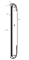
- FIG. 4 is an enlarged sectional view taken along line IV-IV in FIG. 2.
- the mobile phone 1 is made of, for example, a rectangular plate-like smartphone that is long in the vertical direction, and accommodates the display unit 2 on the front side.
- a front cabinet 3 is provided.
- a rectangular dish-shaped metal frame 3a is insert-molded, and a cover adhering recess 3b is formed continuously at the outer peripheral edge.
- the left and right widths of the cover adhering recesses 3b are narrow, and the upper and lower cover adhering recesses 3b are wider than the left and right widths. This left and right width is narrower than that of the prior art, for example, about 0.5 to 1 mm.
- the material of the front-side cabinet 3 is not particularly limited, such as a resin molded product or a metal molded product, but it needs to be able to withstand the heat generated by the laser beam.
- the back side cabinet 4 is coupled to the back side of the front side cabinet 3, and the back side is covered with a rear cover 5.
- a circuit board and a rechargeable battery housed inside are omitted.
- the display unit 2 has a cover 2a made of a transparent glass plate.
- a touch panel (not shown) may be attached to the back side, or the cover 2a itself may be a touch panel.
- a display unit 2b such as a liquid crystal display is attached to the back side of the cover 2a.
- the cover 2a may be made of a transparent resin material that easily transmits laser light, such as an acrylic plate, but needs to be able to withstand the heat generated by the laser light.
- a black print layer is provided on the back surface of the cover 2a to hide the outside of the display area of the display unit 2b.
- this black printed layer is applied not only to the back surface of the corner corresponding to the cover bonding recess, but also to the side surface.
- the black print layer does not transmit and reflect the laser light, but absorbs it easily, and thus plays the role of the heat generating layer 11.
- the black print layer is provided by attaching an ink containing a black dye or pigment to the back and side surfaces of the cover 2a, but it needs to be able to withstand the heat generated by the laser light.
- the heat generating layer 11 may be provided by vapor deposition, film application, primer application, or the like.
- the heat generating layer 11 contains a substance such as carbon that is easier to transfer heat than the resin portion of the cover 2 a and the front cabinet 3. For this reason, when the heat generation layer 11 on the back surface of the corner portion that has received the laser beam vertically generates heat, the heat generation layer 11 on the side surface side that is substantially parallel to the laser beam and cannot receive the heat is also heated. Has come to be transmitted.
- the cover 2a is bonded by the bonding member 10 in the cover bonding recess 3b.
- the adhesive member 10 is obtained by molding a thermoplastic resin material that is melted by heating into a rectangular frame shape in front view and a cross-sectional L shape in advance according to the shape of the concave portion 3b for cover bonding. Although it does not specifically limit as a thermoplastic resin material, it is easy to adhere
- the cover 2a cut out from the glass plate, the adhesive member 10, the display unit 2b, the front-side cabinet 3 and the like formed in an L-shaped cross section in accordance with the cover adhering recess 3b are prepared.
- the adhesive member 10 is clamped between the corner of the cover 2a and the front cabinet 3. If the adhesive member 10 is formed in advance in a L-shaped cross-section and in a rectangular frame shape in front view in accordance with the shape of the cover adhering recess 3b and is attached to a transparent separator with a positioning mark, for example, the cover 2a Compared to the case where the adhesive member is applied to the corner or the cover adhering recess 3b, it is extremely easy to provide the adhesive member 10 in the cover adhering recess 3b having a particularly narrow width in the width direction.
- pressurizing step pressure is applied in a state where the adhesive member 10 is sandwiched between the corner of the cover 2a and the inner surface of the cover adhering recess 3b. This pressurizing step is not always necessary.
- the heat generating layer 11 formed of a black print layer that is easy to absorb the laser light provided on the back surface and the side surface of the cover 2a is heated not by transmitting or reflecting the laser light but mainly by absorbing it. . Even if the side surface cannot receive the laser beam directly, the heat on the back side is transmitted, and heat is thereby generated.
- the adhesive member 10 is sufficiently heated not only on the back side but also on the side surface. Thereby, after the thermoplastic resin material is melted, it is cured again, and the back surface and the side surface of the corner portion of the cover 2a are bonded to the inner surface of the cover bonding recess 3b.
- the heating condition may be, for example, 0.4 to 1.2 J, preferably 0.6 to 1.0 J at which the temperature of the adhesive member 10 is 100 to 150 ° C.
- the cover 2a When the pressurizing step is provided, the cover 2a is pressed against the front cabinet 3 side, so that there is no gap between the unevenness on the corner of the cover 2a or the inner surface of the cover adhering recess 3b and the adhesive member 10.
- the heat generating layer 11 can be heated by laser light to soften, melt or harden the adhesive member 10.
- the periphery of the cover 2a is bonded to the cover adhering recess 3b formed continuously from the outer peripheral edge of the front cabinet 3 by the adhesive member 10 heated by the heat generation of the black print layer which is the heat generating layer 11 of the cover 2a.
- the waterproof mobile phone 1 can be assembled.
- the adhesive member 10 may be either a thermoplastic resin material or a thermosetting resin material, and may be liquid or solid. However, when the adhesive member 10 is shaped in advance in accordance with the adhesion site as in the above-described embodiment, it is easier to handle than the liquid and the adhesive member 10 is easily clamped, and even if the adhesion area is narrow, it is reliable. Can be glued on.
- the bonding area by the bonding member 10 is made as small as possible, it is possible to manufacture a compact mobile phone 1 having a large display area while ensuring waterproofness.
- the heat generating layer 11 is a black printed layer printed on the back and side surfaces of the corners of the cover 2a.
- the heat generating layer easily absorbs laser light on the front and side surfaces of the cover adhering recess 3b on the cover 2a side. 11 may be formed.
- the heat generating layer 11 may be provided with a black print layer containing a large amount of a highly heat-conductive substance such as carbon, or a black tape containing a large amount of a highly heat-conductive substance.
- the bonding step laser light is irradiated from the front side of the cover 2a, in particular, the heating layer 11 on the front side of the cover bonding concave portion 3b where the laser light hits vertically is heated, and the heat is transmitted to the side surface side,
- the adhesive member 10 provided in an L-shaped cross section may be heated to be softened, melted or cured, and the corners of the cover 2a may be bonded to the front cabinet 3.
- the heat generating layer 11 is provided on the cover bonding concave portion 3b side, thereby heating the front side cabinet 3 side and softening the adhesive member 10. Can be melted or cured.
- the present invention may be configured as follows with respect to the above embodiment.
- the heat generating layer 11 is a heat generating layer provided on the back and side black print layers or the cover adhering recesses 3b of the cover 2a.
- the adhesive member 10 may be heated by both the heat generating layer 11 provided in the cover adhering recess 3b as long as it transmits light.
- the adhesive member 10 itself may include a component that generates heat by absorbing laser light and a water material that transmits heat.
- the adhesive member 10 since the adhesive member 10 was made into the frame shape which shape
- the adhesive member 10 is continuous in a rectangular shape, but may be partially discontinuous, and a part of the cover adhering recess 3b (for example, the left and right narrow sides). It may be provided only in.
- the mobile terminal is the mobile phone 1, but PHS (Personal Handy-phone System System), PDA (Personal Digital Assistant), smartphone, personal computer, mobile tool, electronic dictionary, calculator, game machine, etc. There may be.
- PHS Personal Handy-phone System System
- PDA Personal Digital Assistant
Landscapes
- Engineering & Computer Science (AREA)
- Theoretical Computer Science (AREA)
- Physics & Mathematics (AREA)
- General Physics & Mathematics (AREA)
- Computer Hardware Design (AREA)
- Human Computer Interaction (AREA)
- General Engineering & Computer Science (AREA)
- Signal Processing (AREA)
- Telephone Set Structure (AREA)
- Devices For Indicating Variable Information By Combining Individual Elements (AREA)
- Casings For Electric Apparatus (AREA)
Abstract
携帯電話機(1)において、レーザ光を透過するカバー(2a)の外周縁のカバー接着用凹部(3b)に対応する角部の背面及び側面と、カバー接着用凹部(3b)との間に、接着部材(10)を挟持し、カバー(2a)の正面側からレーザ光を照射し、カバー(2a)の角部に設けた発熱層(11)を加熱して接着部材(10)を加熱し、角部の背面及び側面をカバー接着用凹部(3b)の内面に接着する。
Description
本発明は、表示ユニットと、この表示ユニットを覆うカバーと、このカバーが接着されるカバー接着用凹部が形成されたキャビネットとを有する携帯端末及びその製造方法に関するものである。
従来より、表示ユニットを覆う透明なガラスやアクリル板よりなるカバーは、表示ユニットを収容するキャビネットに両面テープなどで接着されていた。
近年、携帯電話機に代表される携帯端末は、表示部を広くしながらも、携帯端末自体の大きさは大きくしないことが求められている。しかも、携帯端末を誤って水の中に落としてしまっても壊れない防水性能が求められている。
携帯端末が一方に長い矩形板状であった場合、特にその幅方向両側の接着面積が狭くなる傾向にあるが、防水性を保つためには、両面テープによる接着面積をある程度大きく保つ必要がある。
そこで、特許文献1のようにレーザ光を利用して熱硬化性樹脂よりなる接着部材を加熱して接着させる接着方法を利用することが考えられる。
特許文献1のようなレーザ光を用いる方法では、通常、レーザ光を接着面に対して垂直に当てて熱硬化性樹脂を硬化させるようにしている。このため、接着面積を小さくするのには限界がある。
本発明は、かかる点に鑑みてなされたものであり、その目的とするところは、表示ユニットの表示面積をできるだけ広くし、携帯端末自体の大きさを抑えながら、カバーをキャビネットに確実に接着することにある。
上記の目的を達成するために、この発明では、レーザ光に対して垂直でないカバーの角部の側面もカバー接着用凹部の内面に接着するようにした。
具体的には、本発明では、表示ユニットと、該表示ユニットを収容するカバー接着用凹部を有するキャビネットと、該表示ユニットの正面から該キャビネットを覆うカバーとを有する携帯端末を対象とし、
上記カバーは、レーザ光を透過する材料よりなり、
上記カバーの外周縁における上記カバー接着用凹部に対応する角部の背面及び側面と該角部に対応するカバー接着用凹部の内面との少なくとも一方に上記レーザ光を吸収する発熱層が設けられ、
上記カバーの角部の背面及び側面が上記発熱層により加熱された接着部材により上記カバー接着用凹部の内面に接着されている。
上記カバーは、レーザ光を透過する材料よりなり、
上記カバーの外周縁における上記カバー接着用凹部に対応する角部の背面及び側面と該角部に対応するカバー接着用凹部の内面との少なくとも一方に上記レーザ光を吸収する発熱層が設けられ、
上記カバーの角部の背面及び側面が上記発熱層により加熱された接着部材により上記カバー接着用凹部の内面に接着されている。
また、本発明では、表示ユニットと、該表示ユニットを収容するカバー接着用凹部を有するキャビネットと、該表示ユニットの正面から該キャビネットを覆うカバーとを有する携帯端末を製造する製造方法を対象とし、
上記製造方法は、
レーザ光を透過する上記カバーの外周縁における上記カバー接着用凹部に対応する角部の背面及び側面と、上記カバー接着用凹部の内面との間に、接着部材を挟持する挟持工程と、
上記カバーの正面側からレーザ光を照射し、該カバーの上記角部及び該角部に対応するカバー接着用凹部の内面の少なくとも一方に設けた発熱部を加熱して上記接着部材を加熱し、上記角部の背面及び側面を上記カバー接着用凹部の内面に接着する接着工程とを含む。
上記製造方法は、
レーザ光を透過する上記カバーの外周縁における上記カバー接着用凹部に対応する角部の背面及び側面と、上記カバー接着用凹部の内面との間に、接着部材を挟持する挟持工程と、
上記カバーの正面側からレーザ光を照射し、該カバーの上記角部及び該角部に対応するカバー接着用凹部の内面の少なくとも一方に設けた発熱部を加熱して上記接着部材を加熱し、上記角部の背面及び側面を上記カバー接着用凹部の内面に接着する接着工程とを含む。
このため、本発明では、レーザ光によってカバー外周縁角部及びカバー収容凹部内面の少なくとも一方の発熱部を加熱するので、カバー外周縁の背面だけでなく、側面もカバー接着用凹部の内面に接着される。このことから、背面側の接着面積を小さくしても側面側で接着強度を保つことができる。このため、防水性を低下させることなく、できるだけ表示面積を広くすることができる。
なお、接着部材は、熱可塑性樹脂材及び熱硬化性樹脂材のどちらでもよく、液状でも固体でもよい。しかし、接着部材を予め接着部位に合わせた形状に成形した場合には、液体よりも取り扱いが容易で接着部材の挟持が容易となり、接着領域が狭い場合でも、確実に接着を行うことができる。
以上説明したように、本発明によれば、レーザ光によってカバーの角部の背面及び側面と接着用凹部の内面の少なくとも一方に設けた発熱部を加熱して接着部材を加熱し、カバー角部の背面及び側面をカバー接着用凹部の内面に接着するようにしたことにより、表示ユニットの表示面積をできるだけ広くしながら携帯端末自体の大きさを抑えることができる。
以下、本発明の実施形態を図面に基づいて説明する。
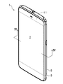
図1~図4は本発明の実施形態の携帯端末としての携帯電話機1を示し、この携帯電話機1は、例えば上下方向に長い矩形板状のスマートフォンよりなり、正面側に表示部2を収容する正面側キャビネット3を有する。正面側キャビネット3は、例えば、矩形皿状の金属フレーム3aがインサート成形され、外周縁部に一段低くなったカバー接着用凹部3bが連続して形成されている。このカバー接着用凹部3bの左右幅は狭く、上下のカバー接着用凹部3bの幅は左右幅に比べて広くなっている。この左右幅は、従来に比べてさらに狭く、例えば0.5~1mm程度となっている。正面側キャビネット3の材質は、樹脂成形品、金属成形品など特に限定されないが、レーザ光による発熱に耐えうるものである必要がある。
図1にも拡大して示すように、正面側キャビネット3の背面側には、背面側キャビネット4が結合され、その背面側がリアカバー5で覆われている。なお、図4では、内部に収容されている回路基板や充電池は省略している。
表示部2は、透明なガラス板よりなるカバー2aを有する。その背面側にタッチパネル(図示せず)が貼り付けられてもよいし、カバー2a自体がタッチパネルでもよい。カバー2aの背面側に液晶ディスプレイなどの表示ユニット2bが貼り付けられている。カバー2aは、アクリル板などの透明でレーザ光を透過しやすい樹脂材料で構成されていてもよいが、レーザ光による発熱に耐えうるものである必要がある。
本実施形態では、カバー2aの背面に表示ユニット2bの表示エリアの外側を隠す黒色印刷層が施されている。本発明では、この黒色印刷層が、カバー接着用凹部に対応する角部の背面だけでなく、側面にも施されている。この黒色印刷層は、レーザ光を透過及び反射するのではなく、吸収しやすいので、発熱層11の役割を果たす。黒色印刷層は、黒色の染料や顔料を含むインクをカバー2aの背面及び側面に付着させることによって設けられるが、レーザ光による発熱に耐えうるものである必要がある。黒色でなくても、レーザ光を吸収する色であればよく、さらに発熱層11を蒸着、フィルムの貼付、プライマーの塗布等によって設けてもよい。発熱層11は、カバー2a及び正面側キャビネット3の樹脂部分よりも熱を伝えやすい、カーボンなどの物質を含んでいる。このため、レーザ光を垂直に受けた角部の背面における発熱層11が発熱したときに、レーザ光とほぼ並行であって、それを充分に受けることができない側面側の発熱層11にも熱が伝わるようになっている。
カバー2aは、カバー接着用凹部3bにおいて、接着部材10によって接着されている。接着部材10は、加熱により溶ける熱可塑性樹脂材をカバー接着用凹部3bの形状に合わせて予め正面視矩形枠状かつ断面L字状に成形したものである。熱可塑性樹脂材としては特に限定されないが、カバー2a及び正面側キャビネット3のいずれにも接着しやすく、これらの材料に悪影響を与えない温度で溶けるものである必要がある。
次に、本発明のカバー2aの貼付手順について説明する。
まず準備工程において、ガラス板から切り出したカバー2a、カバー接着用凹部3bに合わせて断面L字状に成形した接着部材10、表示ユニット2b、正面側キャビネット3等を用意する。
次いで、挟持工程において、カバー2aの角部と、正面側キャビネット3との間に接着部材10を挟持する。接着部材10は、カバー接着用凹部3bの形状に合わせて予め断面L字状かつ正面視矩形枠状に成形し、例えば位置決めの印が付けられた透明なセパレータに貼り付けておけば、カバー2a角部又はカバー接着用凹部3bに接着部材を塗布する場合に比べ、特に幅方向の幅の狭いカバー接着用凹部3bに接着部材10を設けるのが極めて容易となる。
次いで、加圧工程において、カバー2aの角部とカバー接着用凹部3bの内面との間に接着部材10を挟持した状態で、加圧する。この加圧工程は、必ずしも必要ではない。
次いで、接着工程において、カバー2aの正面側からレーザ光を照射する。ここでは、カバー2aの背面及び側面に設けたレーザ光を吸収しやすい黒色印刷層で構成された発熱層11がレーザ光を透過又は反射するのではなく、主に吸収することにより、加熱される。側面は、直接レーザ光を受けることができない場合であっても、背面側の熱が伝達され、そのことで発熱する。このことで、接着部材10は、背面側だけでなく側面側も充分に加熱される。これにより、熱可塑性樹脂材が溶けた後、再び硬化し、カバー2aの角部の背面及び側面がカバー接着用凹部3bの内面に接着される。加熱のための条件は、例えば、接着部材10の温度が100~150℃となる0.4~1.2J好ましくは、0.6~1.0Jとすればよい。なお、ここで、エネルギーJは、レーザ出力をWワット、レーザ焦点径をφmm、走査速度をVmm/secとすれば、J=W×φ/Vで計算される。なお、接着部材10の温度が150~170℃となる1.0~1.2Jのエネルギーであれば、適度に加圧した場合でも、発泡して防水性が保ちにくい。0.4Jよりも小さいと、接着部材10の発熱温度が80℃以下となり接着部材10が充分に軟化、溶融又は硬化しない。
なお、加圧工程を設けた場合、カバー2aを正面側キャビネット3側へ押さえ付けているので、カバー2a角部やカバー接着用凹部3b内面にある凹凸と接着部材10との隙間をなくした状態で、レーザ光により発熱層11を加熱して接着部材10を軟化、溶融又は硬化させることができて有利である。
また、カバー2aの発熱層11である黒色印刷層の発熱によって加熱された接着部材10により、カバー2a周縁が正面側キャビネット3の外周縁部に連続して形成したカバー接着用凹部3bに接着される。そして、従来よりある、内部を見えなくする黒色印刷層等を側面にまで延ばして接着部材10を加熱することができるので、発熱層11を設けるためだけの工程を追加しなくてよい。
そして、接着部材10により、カバー2aと正面側キャビネット3との間を防水可能に密閉させた状態で、回路基板、充電池等を収容して背面側キャビネット4を結合し、リアカバー5で覆うことにより、防水型の携帯電話機1を組み立てることができる。
なお、接着部材10は、熱可塑性樹脂材及び熱硬化性樹脂材のどちらでもよく、液状でも固体でもよい。しかし、上記実施形態のように接着部材10を予め接着部位に合わせた形状に成形した場合には、液体よりも取り扱いが容易で接着部材10の挟持が容易となり、接着領域が狭い場合でも、確実に接着を行うことができる。
このように、接着部材10による接着面積をできるだけ小さくすることで、防水性を確保しながら、表示面積の広いコンパクトな携帯電話機1を製造することができる。
-変形例-
上記実施形態では、発熱層11は、カバー2a角部の背面及び側面に印刷した黒色印刷層としたが、カバー接着用凹部3bのカバー2a側の正面及び側面にレーザ光を吸収しやすい発熱層11を形成してもよい。この発熱層11は、例えば、カーボンなどの伝熱性の高い物質を多く含んだ黒色印刷層を施してもよいし、伝熱性の高い物質を多く含んだ黒色のテープを貼り付けてもよい。
上記実施形態では、発熱層11は、カバー2a角部の背面及び側面に印刷した黒色印刷層としたが、カバー接着用凹部3bのカバー2a側の正面及び側面にレーザ光を吸収しやすい発熱層11を形成してもよい。この発熱層11は、例えば、カーボンなどの伝熱性の高い物質を多く含んだ黒色印刷層を施してもよいし、伝熱性の高い物質を多く含んだ黒色のテープを貼り付けてもよい。
そして、接着工程において、カバー2aの正面側からレーザ光を照射し、特にレーザ光が垂直に当たるカバー接着用凹部3bの正面側の発熱層11を加熱し、その熱が側面側にまで伝達され、断面L字状に設けた接着部材10を加熱して軟化、溶融又は硬化させ、カバー2a角部を正面側キャビネット3に接着するとよい。
本変形例によれば、カバー2a側に発熱層11を設けられない場合でも、カバー接着用凹部3b側に発熱層11を設けることで、正面側キャビネット3側を加熱して接着部材10を軟化、溶融又は硬化させることができる。
(その他の実施形態)
本発明は、上記実施形態について、以下のような構成としてもよい。
本発明は、上記実施形態について、以下のような構成としてもよい。
すなわち、上記実施形態では、発熱層11をカバー2aの背面及び側面の黒色印刷層又はカバー接着用凹部3bに設けた発熱層としているが、カバー2a背面及び側面の発熱層11がレーザ光をある程度透過するものであれば、カバー接着用凹部3bに設けた発熱層11と両方で接着部材10を加熱してもよい。さらには、接着部材10自体がレーザ光を吸収して発熱する成分及び熱を伝達した水材料を含んでいてもよい。
また、上記実施形態では、接着部材10を予め熱可塑性樹脂材を成形した枠状のものとしたので、従来の両面テープのような簡易な方法による貼付を行えるが、粘性の高い液状の接着部材10をディスペンサーなどによりカバー2aの角部の背面及び側面又はカバー接着用凹部3bに塗りつけるようにしてもよい。
さらに、上記実施形態では、接着部材10は、矩形状に連続したものとしているが、一部不連続であってもよく、また、カバー接着用凹部3bの一部(例えば幅の狭い左右両側)にのみ設けられていてもよい。
また、上記実施形態では、携帯端末は、携帯電話機1としたが、PHS(Personal Handy-phone System )、PDA(Personal Digital Assistant)、スマートフォン、パソコン、モバイルツール、電子辞書、電卓、ゲーム機等であってもよい。
なお、以上の実施形態は、本質的に好ましい例示であって、本発明、その適用物や用途の範囲を制限することを意図するものではない。また、各実施形態に記載された技術的特徴は、互いに組合せ可能であり、組み合わせることにより、新しい技術的特徴を形成することができる。
1 携帯電話機(携帯端末)
2 表示部
2a カバー
2b 表示ユニット
3 正面側キャビネット(キャビネット)
3a 金属フレーム
3b 接着用凹部
4 背面側キャビネット
5 リアカバー
10 接着部材
11 発熱層
2 表示部
2a カバー
2b 表示ユニット
3 正面側キャビネット(キャビネット)
3a 金属フレーム
3b 接着用凹部
4 背面側キャビネット
5 リアカバー
10 接着部材
11 発熱層
Claims (4)
- 表示ユニットと、該表示ユニットを覆うカバーと、該カバーが接着されるカバー接着用凹部が形成されたキャビネットとを有する携帯端末であって、
上記カバーは、レーザ光を透過する材料よりなり、
上記カバーの外周縁における上記カバー接着用凹部に対応する角部の背面及び側面と該カバー接着用凹部の内面との少なくとも一方に上記レーザ光を吸収する発熱層が設けられ、
上記カバーの角部の背面及び側面が上記発熱層により加熱された接着部材により上記カバー接着用凹部の内面に接着されている
ことを特徴とする携帯端末。 - 請求項1に記載の携帯端末において、
上記発熱層は、上記カバーよりも熱伝導率が高い
ことを特徴とする携帯端末。 - 表示ユニットと、該表示ユニットを覆うカバーと、該カバーが接着されるカバー接着用凹部が形成されたキャビネットとを有する携帯端末を製造する製造方法であって、
レーザ光を透過する上記カバーの外周縁における上記カバー接着用凹部に対応する角部の背面及び側面と、上記カバー接着用凹部の内面との間に、接着部材を挟持する挟持工程と、
上記カバーの正面側からレーザ光を照射し、該カバーの上記角部及び該角部に対応するカバー接着用凹部の内面の少なくとも一方に設けた発熱部を加熱して上記接着部材を加熱し、上記角部の背面及び側面を上記カバー接着用凹部の内面に接着する接着工程とを含む
ことを特徴とする携帯端末の製造方法。 - 請求項3に記載の携帯端末の製造方法において、
上記挟持工程において、上記カバーの角部と、上記カバー接着用凹部との間に、予め断面L字状に成形された接着部材を挟持する
ことを特徴とする携帯端末の製造方法。
Applications Claiming Priority (2)
| Application Number | Priority Date | Filing Date | Title |
|---|---|---|---|
| JP2013-197064 | 2013-09-24 | ||
| JP2013197064A JP6245911B2 (ja) | 2013-09-24 | 2013-09-24 | 携帯端末及びその製造方法 |
Publications (1)
| Publication Number | Publication Date |
|---|---|
| WO2015045248A1 true WO2015045248A1 (ja) | 2015-04-02 |
Family
ID=52742428
Family Applications (1)
| Application Number | Title | Priority Date | Filing Date |
|---|---|---|---|
| PCT/JP2014/004032 Ceased WO2015045248A1 (ja) | 2013-09-24 | 2014-07-31 | 携帯端末及びその製造方法 |
Country Status (3)
| Country | Link |
|---|---|
| JP (1) | JP6245911B2 (ja) |
| TW (1) | TW201511927A (ja) |
| WO (1) | WO2015045248A1 (ja) |
Citations (7)
| Publication number | Priority date | Publication date | Assignee | Title |
|---|---|---|---|---|
| JP2001092376A (ja) * | 1999-09-20 | 2001-04-06 | Denso Corp | 表示素子およびその製造方法 |
| JP2001198982A (ja) * | 2000-01-20 | 2001-07-24 | Nissha Printing Co Ltd | 加飾プラスチック成形品の製造方法 |
| JP2009173023A (ja) * | 2007-12-25 | 2009-08-06 | Hayakawa Rubber Co Ltd | レーザー接合用シート及びそれを用いた接合方法 |
| JP2009196325A (ja) * | 2008-02-25 | 2009-09-03 | Rb Controls Co | 防水ケースの水密構造 |
| JP2011156858A (ja) * | 2010-01-08 | 2011-08-18 | Hayakawa Rubber Co Ltd | レーザー光を用いた接合方法 |
| WO2012029347A1 (ja) * | 2010-09-03 | 2012-03-08 | アルプス電気株式会社 | ガラス複合体、ガラス複合体を用いた電子機器、及び、入力装置 |
| JP2012218316A (ja) * | 2011-04-11 | 2012-11-12 | Hayakawa Rubber Co Ltd | レーザー光を用いた部材の接着方法 |
-
2013
- 2013-09-24 JP JP2013197064A patent/JP6245911B2/ja not_active Expired - Fee Related
-
2014
- 2014-07-31 WO PCT/JP2014/004032 patent/WO2015045248A1/ja not_active Ceased
- 2014-08-21 TW TW103128856A patent/TW201511927A/zh unknown
Patent Citations (7)
| Publication number | Priority date | Publication date | Assignee | Title |
|---|---|---|---|---|
| JP2001092376A (ja) * | 1999-09-20 | 2001-04-06 | Denso Corp | 表示素子およびその製造方法 |
| JP2001198982A (ja) * | 2000-01-20 | 2001-07-24 | Nissha Printing Co Ltd | 加飾プラスチック成形品の製造方法 |
| JP2009173023A (ja) * | 2007-12-25 | 2009-08-06 | Hayakawa Rubber Co Ltd | レーザー接合用シート及びそれを用いた接合方法 |
| JP2009196325A (ja) * | 2008-02-25 | 2009-09-03 | Rb Controls Co | 防水ケースの水密構造 |
| JP2011156858A (ja) * | 2010-01-08 | 2011-08-18 | Hayakawa Rubber Co Ltd | レーザー光を用いた接合方法 |
| WO2012029347A1 (ja) * | 2010-09-03 | 2012-03-08 | アルプス電気株式会社 | ガラス複合体、ガラス複合体を用いた電子機器、及び、入力装置 |
| JP2012218316A (ja) * | 2011-04-11 | 2012-11-12 | Hayakawa Rubber Co Ltd | レーザー光を用いた部材の接着方法 |
Also Published As
| Publication number | Publication date |
|---|---|
| JP2015064429A (ja) | 2015-04-09 |
| JP6245911B2 (ja) | 2017-12-13 |
| TW201511927A (zh) | 2015-04-01 |
Similar Documents
| Publication | Publication Date | Title |
|---|---|---|
| WO2015045250A1 (ja) | 携帯端末及びその製造方法 | |
| WO2020248532A1 (zh) | 一种曲面玻璃盖板及其制作方法 | |
| US9149998B2 (en) | Attaching window assembly using optical welding | |
| TW201516530A (zh) | 電子裝置、電子裝置蓋板的組裝方法及黏接結構 | |
| US20200223113A1 (en) | Metal resin composite-molded article and method for manufacturing same | |
| CN111433687B (zh) | 一种可穿戴设备 | |
| WO2015097966A1 (ja) | 携帯端末及びその製造方法 | |
| US20160016395A1 (en) | Device Structures Bonded With Adhesive Films | |
| JP6245911B2 (ja) | 携帯端末及びその製造方法 | |
| CN219339827U (zh) | 手持式贴膜辅助加热装置 | |
| KR101324591B1 (ko) | 휴대용 단말기의 홈키 제조방법 | |
| US10203450B2 (en) | Backlight module and the manufacturing method thereof | |
| JP2015126347A (ja) | 携帯端末及びその製造方法 | |
| JP6113037B2 (ja) | 携帯端末及びその製造方法 | |
| CN102946697B (zh) | 薄膜电路板制造方法及其薄膜电路板 | |
| WO2022082956A1 (zh) | 移动终端及移动终端装配方法 | |
| CN106952578A (zh) | 一种显示屏面板组件及其制作方法、移动终端 | |
| WO2021159495A1 (zh) | 电子货架标签及其制造方法 | |
| WO2015159518A1 (ja) | 電子機器及びその筐体の製造方法 | |
| CN113269291B (zh) | 电子货架标签及其制造方法 | |
| TWI440420B (zh) | 薄膜電路板製造方法及其薄膜電路板 | |
| CN214252646U (zh) | 一种高可靠性且防止异响的背光源 | |
| CN107031055A (zh) | 无中间介质激光熔接工艺 | |
| CN115171553B (zh) | 一种曲面显示模组及制备方法 | |
| JP6393133B2 (ja) | レーザー光を用いた接合方法及び剥離方法 |
Legal Events
| Date | Code | Title | Description |
|---|---|---|---|
| 121 | Ep: the epo has been informed by wipo that ep was designated in this application |
Ref document number: 14849848 Country of ref document: EP Kind code of ref document: A1 |
|
| NENP | Non-entry into the national phase |
Ref country code: DE |
|
| 122 | Ep: pct application non-entry in european phase |
Ref document number: 14849848 Country of ref document: EP Kind code of ref document: A1 |