WO2015040889A1 - ブレーキ装置 - Google Patents
ブレーキ装置 Download PDFInfo
- Publication number
- WO2015040889A1 WO2015040889A1 PCT/JP2014/063535 JP2014063535W WO2015040889A1 WO 2015040889 A1 WO2015040889 A1 WO 2015040889A1 JP 2014063535 W JP2014063535 W JP 2014063535W WO 2015040889 A1 WO2015040889 A1 WO 2015040889A1
- Authority
- WO
- WIPO (PCT)
- Prior art keywords
- brake device
- push rod
- piston
- communication hole
- valve body
- Prior art date
- Legal status (The legal status is an assumption and is not a legal conclusion. Google has not performed a legal analysis and makes no representation as to the accuracy of the status listed.)
- Ceased
Links
Images






Classifications
-
- B—PERFORMING OPERATIONS; TRANSPORTING
- B60—VEHICLES IN GENERAL
- B60T—VEHICLE BRAKE CONTROL SYSTEMS OR PARTS THEREOF; BRAKE CONTROL SYSTEMS OR PARTS THEREOF, IN GENERAL; ARRANGEMENT OF BRAKING ELEMENTS ON VEHICLES IN GENERAL; PORTABLE DEVICES FOR PREVENTING UNWANTED MOVEMENT OF VEHICLES; VEHICLE MODIFICATIONS TO FACILITATE COOLING OF BRAKES
- B60T8/00—Arrangements for adjusting wheel-braking force to meet varying vehicular or ground-surface conditions, e.g. limiting or varying distribution of braking force
- B60T8/32—Arrangements for adjusting wheel-braking force to meet varying vehicular or ground-surface conditions, e.g. limiting or varying distribution of braking force responsive to a speed condition, e.g. acceleration or deceleration
- B60T8/34—Arrangements for adjusting wheel-braking force to meet varying vehicular or ground-surface conditions, e.g. limiting or varying distribution of braking force responsive to a speed condition, e.g. acceleration or deceleration having a fluid pressure regulator responsive to a speed condition
- B60T8/341—Systems characterised by their valves
-
- B—PERFORMING OPERATIONS; TRANSPORTING
- B60—VEHICLES IN GENERAL
- B60T—VEHICLE BRAKE CONTROL SYSTEMS OR PARTS THEREOF; BRAKE CONTROL SYSTEMS OR PARTS THEREOF, IN GENERAL; ARRANGEMENT OF BRAKING ELEMENTS ON VEHICLES IN GENERAL; PORTABLE DEVICES FOR PREVENTING UNWANTED MOVEMENT OF VEHICLES; VEHICLE MODIFICATIONS TO FACILITATE COOLING OF BRAKES
- B60T8/00—Arrangements for adjusting wheel-braking force to meet varying vehicular or ground-surface conditions, e.g. limiting or varying distribution of braking force
- B60T8/32—Arrangements for adjusting wheel-braking force to meet varying vehicular or ground-surface conditions, e.g. limiting or varying distribution of braking force responsive to a speed condition, e.g. acceleration or deceleration
- B60T8/34—Arrangements for adjusting wheel-braking force to meet varying vehicular or ground-surface conditions, e.g. limiting or varying distribution of braking force responsive to a speed condition, e.g. acceleration or deceleration having a fluid pressure regulator responsive to a speed condition
- B60T8/36—Arrangements for adjusting wheel-braking force to meet varying vehicular or ground-surface conditions, e.g. limiting or varying distribution of braking force responsive to a speed condition, e.g. acceleration or deceleration having a fluid pressure regulator responsive to a speed condition including a pilot valve responding to an electromagnetic force
- B60T8/3615—Electromagnetic valves specially adapted for anti-lock brake and traction control systems
- B60T8/3675—Electromagnetic valves specially adapted for anti-lock brake and traction control systems integrated in modulator units
- B60T8/368—Electromagnetic valves specially adapted for anti-lock brake and traction control systems integrated in modulator units combined with other mechanical components, e.g. pump units, master cylinders
-
- B—PERFORMING OPERATIONS; TRANSPORTING
- B60—VEHICLES IN GENERAL
- B60T—VEHICLE BRAKE CONTROL SYSTEMS OR PARTS THEREOF; BRAKE CONTROL SYSTEMS OR PARTS THEREOF, IN GENERAL; ARRANGEMENT OF BRAKING ELEMENTS ON VEHICLES IN GENERAL; PORTABLE DEVICES FOR PREVENTING UNWANTED MOVEMENT OF VEHICLES; VEHICLE MODIFICATIONS TO FACILITATE COOLING OF BRAKES
- B60T8/00—Arrangements for adjusting wheel-braking force to meet varying vehicular or ground-surface conditions, e.g. limiting or varying distribution of braking force
- B60T8/32—Arrangements for adjusting wheel-braking force to meet varying vehicular or ground-surface conditions, e.g. limiting or varying distribution of braking force responsive to a speed condition, e.g. acceleration or deceleration
- B60T8/34—Arrangements for adjusting wheel-braking force to meet varying vehicular or ground-surface conditions, e.g. limiting or varying distribution of braking force responsive to a speed condition, e.g. acceleration or deceleration having a fluid pressure regulator responsive to a speed condition
- B60T8/48—Arrangements for adjusting wheel-braking force to meet varying vehicular or ground-surface conditions, e.g. limiting or varying distribution of braking force responsive to a speed condition, e.g. acceleration or deceleration having a fluid pressure regulator responsive to a speed condition connecting the brake actuator to an alternative or additional source of fluid pressure, e.g. traction control systems
- B60T8/4809—Traction control, stability control, using both the wheel brakes and other automatic braking systems
- B60T8/4827—Traction control, stability control, using both the wheel brakes and other automatic braking systems in hydraulic brake systems
- B60T8/4863—Traction control, stability control, using both the wheel brakes and other automatic braking systems in hydraulic brake systems closed systems
- B60T8/4872—Traction control, stability control, using both the wheel brakes and other automatic braking systems in hydraulic brake systems closed systems pump-back systems
Definitions
- the present invention relates to a brake device that controls a braking force for each wheel of a vehicle with a brake fluid.
- the brake device includes a housing in which an oil passage through which brake fluid pumped from the master cylinder flows is formed, and an electric pump that sucks brake fluid from a reservoir tank provided in the housing.
- a pressure-increasing and pressure-reducing solenoid valve that is attached to the housing and controls brake fluid to each wheel cylinder of the wheel, and a control mechanism that controls the operation of each of the pressure-increasing and pressure-reducing solenoid valves and the electric pump. ing.
- the reservoir tank is formed inside the housing, and has one end connected to the other end of the brake fluid passage connected to each wheel cylinder via the pressure reducing solenoid valve, and a cylinder connected to the master cylinder.
- a piston made of synthetic resin that is slidably provided in the cylinder and urged in a direction to reduce the volume of the cylinder by a coil spring; and provided on the upper side of the cylinder, the master cylinder and the cylinder
- a check valve mechanism for controlling brake fluid between the hydraulic chamber and the hydraulic chamber.
- the check valve mechanism includes a seat member in which a brake fluid pressure fluid passage communicating with the master cylinder and a communication hole communicating with the cylinder are formed, and the communication is performed by seating on a valve seat included in the seat member.
- a ball valve body that opens and closes one end opening of the hole, a valve spring that biases the ball valve body in a valve seat direction, and when the piston slides upward by a predetermined amount by the spring force of the coil spring,
- a metal push rod that opens the one end opening of the communication hole by separating the ball valve body from the valve seat against the spring force of the valve spring through the communication hole by being pushed up by a piston; It has.
- the piston moves upward in the cylinder by the spring force of the coil spring, and pushes up the push rod to move the ball valve body to the valve seat.
- the brake fluid pressure of the master cylinder is introduced into the cylinder from the brake fluid pressure passage through the communication hole.
- brake hydraulic pressure is introduced into the cylinder from the wheel cylinder via the pressure reducing solenoid valve, the piston moves downward against the spring force of the coil spring, and the push rod is released from being pushed up.
- the ball valve body is seated on the valve seat by the spring force of the valve spring to close one end opening of the communication hole.
- the brake device has a check valve mechanism structure in which the inner diameter of the communication hole of the seat member is formed larger on the ball valve body side and smaller on the piston side.
- the present invention has been devised in view of the actual situation of the conventional brake device, and the surface of the push rod and the piston is increased by increasing the diameter of the end of the push rod on the piston side by changing the structure of the seat member.
- a brake device capable of suppressing an increase in pressure is provided.
- the push rod has one end portion that comes into contact with the valve body and the other end portion that comes into contact with the upper surface portion of the piston, and the area of the other end portion is that of the one end portion.
- the seat member of the check valve mechanism is formed with an area that is larger than the area, and a recess that opens toward the hydraulic pressure chamber is formed at a position opposite to the opening of the one end.
- a retainer having a sliding hole for slidably supporting the other end of the push rod is fixed to the push rod, and at least one of the push rod and the retainer is connected to the recess and the hydraulic chamber.
- the passage part to be formed is formed.
- the surface pressure between the other end of the push rod and the upper surface of the piston can be reduced.
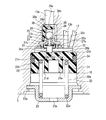
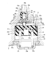
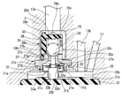
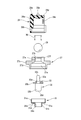
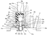
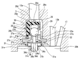
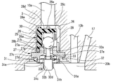
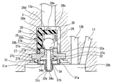
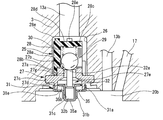
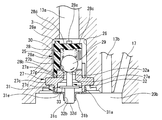
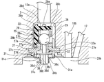
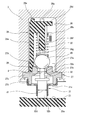
- FIG. 1 is a hydraulic circuit diagram provided for an embodiment of a brake device according to the present invention. It is a longitudinal cross-sectional view which shows the reservoir tank provided to this embodiment, and the check valve mechanism opened. It is a longitudinal cross-sectional view which shows the reservoir tank provided to this embodiment, and the check valve mechanism closed. It is a principal part expanded sectional view of the check valve mechanism with which this embodiment is provided. It is an exploded view of the check valve mechanism provided for this embodiment. It is a perspective view of the retainer provided to a check valve mechanism. It is a longitudinal cross-sectional view of the filter provided to a check valve mechanism. It is principal part sectional drawing of the check valve mechanism with which 2nd Embodiment of this invention is provided.
- this brake device has a hydraulic pressure provided between the master cylinder 1 and each wheel cylinder 2 that generates a brake pressure having a height corresponding to the depression amount of the brake pedal 02. It is formed in the control unit 01. A master reservoir 18 that stores excess brake fluid of the master cylinder 1 is connected.
- the hydraulic control unit 01 has a substantially rectangular parallelepiped housing 3 formed of an aluminum alloy block, and the master cylinder 1 and the front wheel left and right (FR, FL) side and rear wheel left and right (RR, A pair of main passages 4 and 4 that communicate with each wheel cylinder 2 on the RL) side, and the main passages 4 and 4 are provided to control the brake fluid pressure from the master cylinder 1 to each wheel cylinder 2.
- the pressure increasing valves 6 and the wheel cylinders 2 are connected to each other by wheel cylinder ports 12 formed in the upper surface of the housing 3.
- the master cylinder 1 and the hydraulic pressure control unit 01 are connected to the main passages 4 and 4 via master cylinder ports 4a and 4a formed in the port connection surface of the housing 3.
- the master cylinder 1 and each reservoir tank 10 are connected by branch passages 13a and 13a which are oil passages branched from the main passages 4 and 4, and the intake side of each reservoir tank 10 and each plunger pump 9 is connected.
- the reservoir tanks 10 and the pressure reducing valves 7 communicate with each other via hydraulic pressure passages 17 and 17 that are oil passages.
- each plunger pump 9 and each wheel cylinder 2 are connected by each sub passage 8, and each pressure increasing valve 6 corresponding to each wheel cylinder 2 is provided on each sub passage 8. .
- the plunger pump 9 is provided with check valves 14 and 14 that allow the flow of the brake fluid only from the discharge port toward each pressure increasing valve 6.
- Gate-out valves 15 and 15 are provided on the upstream side of the pressure increasing valves 6 in the main passage 4, and each of the gate-out valves 15 is a normally-open solenoid type electromagnetic on-off valve that is used during normal braking. The valve is opened when the ABS is operated, and is closed when the behavior is controlled.
- Each gate-out valve 15 has hydraulic pressure passages 4b and 4b provided with check valves 16 and 16 for blocking the flow of brake fluid from each plunger pump 9, respectively. That is, each check valve 16 allows only the flow of the brake fluid pressure in the direction from the master cylinder 1 toward each wheel cylinder 2 and blocks the flow in the opposite direction.
- Each pressure-increasing valve 6 controls the brake fluid pressure from the master cylinder 1 to be able to supply each wheel cylinder 2 during normal braking operation, while each pressure-reducing valve 7 disturbs the behavior of the vehicle in which the wheel slips.
- the brake fluid in each wheel cylinder 2 is returned to each reservoir tank 10 and temporarily stored.
- Each of the pressure-increasing and pressure-reducing valves 6 and 7 is opened and closed by a control current output from a control unit (not shown) so that the brake fluid pressure in each wheel cylinder 2 is increased, reduced and maintained. It has become.
- each reservoir tank 10 passes through each gate-out valve 15 from the hydraulic pressure passage 13b through each gate-out valve 15 when each plunger pump 9 is operated by the pump motor 11. Returned to 1.
- each plunger pump 9 is operated by a pump motor 11, and each gate-out valve 15 is closed by a control unit, and the wheel cylinder 2 side on which the hydraulic pressure is to be applied.
- the pressure increasing valve 6 is opened. Therefore, the brake hydraulic pressure discharged from each plunger pump 9 is sent to the predetermined wheel cylinder 2 through each pressure increasing valve 6 through the sub passage 8 so as to control the internal pressure of each wheel cylinder 2. It has become.
- each reservoir tank 10 is provided with a bottomed cylindrical cylinder 20 formed in the lower end portion of the housing 3, and is provided in the cylinder 20 so as to be slidable up and down.
- a piston 21 that is divided into an air chamber 20a and a hydraulic chamber 20b that temporarily stores brake fluid in the interior 20 and is elastically mounted in the air chamber 20a.
- the piston 21 has a volume of the hydraulic chamber 20b.
- a coil spring 22 that is a first biasing member that biases in a decreasing direction, that is, upward in the drawing.
- the cylinder 20 has a bottom opening at the lower end closed by a lid member 23, an upper end connected to the other end of the branch passage 13 a connected to the master cylinder 1, and one end The other end portion of each hydraulic pressure passage 13b whose portion is connected to each plunger pump 9 is connected. Further, the other end portion of the fluid pressure passage 17 to which one end portion is connected to each pressure reducing valve 7 is connected to the side portion of each fluid pressure passage 13b.
- the lid member 23 is formed in a cup shape in cross section with a metal material, an outer peripheral flange portion 23a is fixed to the lower end opening edge of the cylinder 20 by caulking, and a lower end portion 22a of the coil spring 22 is attached to the inner surface of the bottom portion. Is held and functions as a spring retainer. Further, an air vent hole 23b is formed in the center so as to penetrate the air chamber 20a so as to ensure good slidability of the piston 21.
- the piston 21 is integrally formed of a synthetic resin material, and an annular convex portion 21b is integrally formed on the outer peripheral side of the upper surface 21a facing the hydraulic chamber 20b, and the fitting is formed on the upper outer peripheral surface.
- An oil seal 24 that is slidably contacted with the inner peripheral surface of the cylinder 20 to seal the hydraulic chamber 20b is fitted and fixed in the groove 21c.
- a concave groove 21d is formed in the lower part of the piston 21, and the upper end portion 22b of the coil spring 22 is elastically supported on the bottom surface of the concave groove 21d, and at the substantially central position of the bottom surface.
- a cylindrical guide portion 21e that guides and supports the upper end portion of the coil spring 22 is integrally provided.
- a check valve mechanism 25 as a pressure regulating valve is provided at a position facing the hydraulic pressure chamber 20b of the cylinder 20, that is, a position on the side of each branch passage 13a.
- each check valve mechanism 25 has a cylindrical valve hole 26 formed above the cylinder 20 and a cylindrical shape fixed by caulking near the lower end opening of the valve hole 26.
- a valve spring 30 as a second urging member for urging the ball valve body 29 in the direction of the seat member 27 and a sliding hole 31c, which will be described later, are formed in the center by being press-fitted and fixed to the lower portion of the seat member 27.
- a metal retainer 31 and a pusher which is slidably supported in the sliding hole 31c of the retainer 31 and opens and closes the ball valve body 29 by the vertical movement of the piston 21.
- Yuroddo 32, and a is a.
- a communication hole 27a that communicates the other end portion of the branch passage 13a and the hydraulic chamber 20b is formed substantially at the center, and the ball valve is formed at the upper end opening edge of the communication hole 27a.
- An annular tapered valve seat 27b is formed on which the body 29 is seated.
- the seat member 27 is integrally formed with the disk-like fixing flange 27c that is caulked and fixed near the lower end opening of the valve hole 26 on the outer peripheral side, and at the lower part of the fixing flange 27c.
- a thin cylindrical retainer fixing portion 27d is integrally formed, and a substantially conical concave portion 27e is formed inside the lower portion.
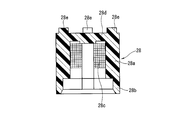
- the filter member 28 is formed in a cylindrical shape with a synthetic resin material, and a step portion 28 b formed around the lower end opening of the peripheral wall 28 a passes through the communication hole 27 a of the sheet member 27. While being press-fitted and fixed to the outer periphery of the cylindrical upper end portion 27f to be formed, mesh portions 28c are integrally formed at four locations in the circumferential direction of the peripheral wall 28a. The brake fluid flowing into the hydraulic pressure chamber 20b from the branch passage 13a is filtered by the mesh portions 28c.
- each projection 28e is provided on the outer peripheral side of the upper surface of the upper wall 28d, and when the filter member 28 is carelessly detached from the cylindrical upper end portion 27f of the sheet member 27, the projection 28e A gap is formed between the upper surface and the upper wall surface of the valve hole 26, and a passage is formed using this gap.
- the ball valve body 29 is formed of a metal material and is biased in a direction in which the valve spring 30 is seated on the valve seat 27b of the seat member 27, that is, the communication hole 27a is closed.
- the piston 21 is pushed up via the push rod 32 against the spring force of the valve spring 30 as the piston 21 moves upward by more than a predetermined distance, and is separated from the valve seat 27b to open one end opening of the communication hole 27a. It has become.
- the retainer 31 is formed in a stepped cylindrical shape, and has an upper large-diameter cylindrical portion 31 a that is press-fitted and fixed to the inner peripheral surface of the retainer fixing portion 27 d of the sheet member 27.
- the small-diameter cylindrical portion 31b is integrally formed at the lower center of the large-diameter cylindrical portion 31a and faces the hydraulic chamber 20b of the cylinder 21.
- the small-diameter cylindrical portion 31b is formed with the sliding hole 31c in which an inner peripheral surface slides a large-diameter rod portion 32b of a push rod 32 described later.
- a flat annular portion 31d is formed at the step portion between the large diameter cylindrical portion 31a and the small diameter cylindrical portion 31b, and the annular portion 31d includes the concave portion 27e of the sheet member 27 and the liquid.
- Four passage holes 31e which are passage portions communicating with the pressure chamber 20d are formed through. Each passage hole 31e is formed in a long hole shape along the circumferential direction of the annular portion 31c, and is arranged at equal intervals in the circumferential direction.
- the push rod 32 is formed of a metal in a stepped shaft shape, and a flat upper end surface (tip surface) 32 c is inserted into the ball valve body through the communication hole 27 a of the seat member 27.
- a small-diameter rod portion 32a which is a first portion on one end side that is separated from and in contact with 29, and a lower end edge (the other end portion side) of the small-diameter rod portion 32a are integrally provided, and a lower end surface (front end surface) 32d is provided on the piston 21.
- a large-diameter rod 32b that is a second part that is separated from and in contact with the upper surface 21a.
- the small-diameter rod portion 32a has an outer diameter that is sufficiently smaller than the inner diameter of the communication hole 27a of the sheet member 27 and is always disposed in the communication hole 27a, and has an outer peripheral surface and an inner peripheral surface of the communication hole 27a.
- a cylindrical passage 27g is formed between them.
- the large-diameter rod portion 32b has an axial length that is substantially the same as the small-diameter rod portion 32a, and an outer diameter that is sufficiently larger than the small-diameter rod portion 32a.
- the area of 32d is formed sufficiently larger than the upper end surface 32c of the small diameter rod portion 32a.
- the large-diameter rod portion 32b is slidably guided and supported in the sliding hole 31c of the retainer 31.
- a stopper portion 33 for restricting the maximum movement position of the push rod 32 in the direction of the piston 21 is press-fitted and fixed to the step portion formed between the small-diameter rod portion 32a and the large-diameter rod portion 32b.
- the stopper portion 33 is integrally formed of a metal material or a synthetic resin material, and includes a central cylindrical portion 33a and a flange-like stopper piece 33b extending in a radial direction from the lower end edge of the cylindrical portion 33a.
- the cylindrical portion 33a has an inner diameter slightly smaller than the outer diameter of the step portion of the push rod 32, and is press-fitted into the step portion on the small diameter rod portion 32a side.
- the stopper piece 33b is formed so that its outer diameter is slightly larger than the outer diameter of the small-diameter cylindrical portion 31b of the retainer 31, and a large amount of brake fluid is introduced into the hydraulic pressure chamber 20b of the cylinder 20 so that the piston 21 is predetermined.
- each check valve mechanism 25 When the movement is greatly lowered as described above, the maximum downward movement position of the push rod 32 is regulated by contacting the upper surface of the annular portion 31d, that is, the downward drop is prevented.
- FIG. 5 is an exploded view.
- the filter member 28 containing the valve spring 30 and the ball valve body 29 therein is press-fitted and fixed to the cylindrical upper end portion 27f of the seat member 27 via the cylindrical step portion 28b. At this time, the ball valve body 29 is seated on the valve seat 27 b of the seat member 7 by the spring force of the valve spring 30.
- the push rod 32 is assembled from above the retainer 31. That is, the cylindrical portion 33a of the stopper portion 33 is press-fitted and fixed in advance to the small-diameter rod portion 32a of the push rod 32, and the large-diameter rod portion 32b of the push rod 32 is slid on the small-diameter cylindrical portion 31b of the retainer 31 in this state.
- the stopper piece 33b is brought into contact with the upper end surface of the annular portion 31d of the retainer 31 to hold the assembly position of the push rod 32 by being inserted into the movement hole 31c from above.
- the retainer 31 assembled with the push rod 32 is press-fitted into the sheet member 27 from below. That is, while holding the retainer 31, the outer peripheral surface of the large-diameter cylindrical portion 31 a of the retainer 31 is retained by the retainer fixing portion while the small-diameter rod portion 32 a of the push rod 32 is inserted into the communication hole 27 a through the recess 27 e of the sheet member 27. It press-fits and fixes to the inner peripheral surface of 27d.
- the unit of the check valve mechanism 25 is positioned inside the valve hole 26 and the peripheral wall of the lower end opening of the valve hole 26 is caulked through the fixing flange 27c of the seat member 27. Thereby, as shown in FIG. 4, the assembly of the check valve mechanism 25 unit to the housing 3 is completed.
- the piston 21 is accommodated in the cylinder 20, and the flange portion 23 a is positioned and held in the lower end opening of the cylinder 20 while positioning the coil spring 22 at the lower portion of the piston 21 through the lid member 23. Subsequently, if the peripheral wall of the lower end opening of the cylinder 20 is caulked, the flange portion 23a of the lid member 23 is fixed, and the assembly of each component of the reservoir tank 10 is completed.
- the piston 21 is biased to the upper position by the spring force of the coil spring 22, and the upper end outer peripheral portion of the piston 21 abuts against the upper end peripheral wall of the cylinder 20.
- the above upward movement is restricted.
- the piston upper surface 21a pushes up the push rod 32 while contacting the lower surface 32d of the large-diameter rod portion 32b of the push rod 32. Is opened.
- the brake fluid is introduced into the hydraulic chamber 20b of the cylinder 20 through the pressure reducing valves 7 or the master cylinder 1 is driven from the hydraulic chamber 29b by driving the plunger pump 9 during traveling of the vehicle or brake operation.
- the piston 21 slides up and down in the cylinder 20, and the lower surface 32 d of the large-diameter rod portion 32 b comes in contact with and separates from the upper surface 21 a of the piston 21.
- the structure of the check valve mechanism 25 is improved, and the large-diameter rod portion 32b of the push rod 32 at the time of assembly is temporarily placed in the sliding hole 31c of the small-diameter cylindrical portion 31b of the retainer 31.
- the stopper piece 33b Inserted from above, the stopper piece 33b is brought into contact with the upper end surface of the annular portion 31d of the retainer 31 to hold the assembly position of the push rod 32, and then the retainer 31 is press-fitted into the seat member 27 from below. Since the push rod 32 can be inserted into the seat member 27, the outer diameter of the large-diameter rod portion 32b of the push rod 32 that contacts the upper surface 21a of the piston 21 can be made as large as possible. As a result, the surface pressure at the time of contact with the piston upper surface 21b can be reduced. As a result, the occurrence of a dent in the piston upper surface 21a is suppressed, and durability can be improved.
- the retainer 31 since the retainer 31 is merely interposed, the structure can be simplified and the manufacturing work and the assembling work can be prevented from becoming complicated. In this respect as well, an increase in cost can be suppressed.
- FIG. 8 shows a second embodiment of the present invention in which the structure of the push rod 32 is changed.
- the outer diameter of the entire push rod 32 is formed to be the same as the outer diameter of the small-diameter rod portion 32a, and an insertion portion 34 having a substantially U-shaped longitudinal section is press-fitted and fixed from below on the outer peripheral surface of the lower end rod portion 32e.
- the insertion portion 34 is formed to have an outer diameter that is substantially the same as that of the large-diameter rod portion 32b of the first embodiment. Therefore, the area of the lower end surface 34a is also substantially the same as the lower end surface 32d of the large-diameter rod portion 32b. It is formed in size. Further, a flange-like stopper piece 34 b that also serves as the stopper portion 33 is formed integrally with the upper end edge of the fitting insertion portion 34.
- FIG. 9 shows the third embodiment.
- the push rod 32 has the same structure as that of the first embodiment, and the outer diameter of the large-diameter rod portion 32b is larger than that of the fitting insertion portion used in the second embodiment.
- the large insertion portion 35 is press-fitted and fixed from below.
- the fitting insertion portion 35 has an area of the lower end surface 35a further increased, and a flange-like stopper piece 35b is integrally formed at the upper end edge.
- a flange-like stopper piece 35b is integrally formed at the upper end edge.
- FIG. 10 shows a fourth embodiment, in which the outer diameter of the large-diameter rod portion 32b of the push rod 32 in the first embodiment is further increased, and a flange-like position is formed at the position of the step portion between the small-diameter rod portion 32a.
- the stopper portion 33 is integrally formed of a synthetic resin material. As the diameter of the large-diameter rod portion 32b is increased, the inner diameter of the sliding hole 31c of the retainer 31 is increased accordingly.
- the area of the lower end surface 32d is further increased by further increasing the diameter of the large-diameter rod portion 32b, so that the surface pressure with the upper surface 21a of the piston 1 is further reduced as in the third embodiment.
- FIG. 11 shows a fifth embodiment in which the structure of the large-diameter rod portion of the push rod 32 is changed.
- the push rod 32 has the same structure as that of the first embodiment, but the large diameter rod portion 36 has a central shaft portion 36a and a central shaft portion 36a. It is composed of four protrusions 36b having a substantially cross-shaped cross section extending in the radial direction. An arcuate groove 36c is formed between the protrusions 36b, and each groove 36c serves as a brake fluid passage groove.
- a flange-like stopper portion 33 is integrally provided at the step portion between the small-diameter rod portion 32a and the large-diameter rod portion 36.
- the contact surface pressure with the upper surface 21a of the piston 21 is reduced. Can be made sufficiently small.
- the surface pressure at the time of contact with the piston upper surface 21a is largely dispersed by the projections 36b, the surface pressure can be further reduced. As a result, the surface pressure with the upper surface 21a of the piston 1 is further reduced, and it is possible to further suppress the occurrence of a dent in the piston upper surface 21a and the generation of vibration sound.
- each groove 36c functions as a passage groove in addition to each passage hole 31e of the retainer 31, when the ball valve body 29 is opened, the fluid pressure chamber 20b passes through the recess 27e and the branch passage 13b. Thus, the fluidity of the brake fluid to the master cylinder 1 is improved.
- the assembly workability is improved by integrating the stopper piece 33 with the push rod 32, as in the fourth embodiment.
- FIGS. 13 to 17 show sixth to tenth embodiments, which basically correspond to the first to fifth embodiments, except that the large-diameter cylindrical portion 31a of the retainer 31 of each embodiment is different.
- the outer diameter of the large-diameter cylindrical portion 31a is press-fitted and fixed to the outer peripheral surface of the retainer fixing portion 27d of the sheet member 27. .
- the peripheral wall 28a is formed to extend along the axial direction, and the entire area of the mesh portion 28c is also enlarged and formed in the axial direction accordingly.
- a restriction shaft portion 28f is integrally suspended at the central position of the lower end surface of the upper wall 28d, and the restriction shaft portion 28f is formed by extending the peripheral wall 28 in the axial direction.
- the excessive movement of 29 in the upward direction is regulated by the tip surface 28g.
- the restriction shaft portion 28f guides and holds the inner peripheral side of the valve spring 30 disposed on the outer peripheral side, and restricts bending deformation in the lateral direction when the valve spring 30 expands and contracts. It has become.
- the communication hole 27a is formed so that the entire inner diameter d is slightly smaller than the outer diameter d1 of the large-diameter rod portion 32b of the push rod 32.
- restriction shaft portion 28f restricts excessive upward movement of the ball valve body 29, and the lateral deformation of the valve spring 30 can be suppressed, so that the behavior of the ball valve body 29 and the valve spring 30 is suppressed. Can be stabilized.
- the brake fluid pressure in the fluid pressure chamber 20b is increased, and the piston 21 exceeds a predetermined value.
- the stopper portion 33 or the stopper pieces 34b and 35b abut against the upper surface of the annular portion 31d to regulate the maximum downward movement position of the push rod 32.
- the stopper portion 33 or the stopper pieces 34b and 35b Can be omitted. In this case, since the push rod 32 is always in contact with the upper surface 21a of the piston 21, the hitting sound can be suppressed and the cost can be suppressed.
Landscapes
- Engineering & Computer Science (AREA)
- Physics & Mathematics (AREA)
- Fluid Mechanics (AREA)
- Transportation (AREA)
- Mechanical Engineering (AREA)
- Electromagnetism (AREA)
- Regulating Braking Force (AREA)
- Valves And Accessory Devices For Braking Systems (AREA)
- Transmission Of Braking Force In Braking Systems (AREA)
Abstract
Description
〔第1実施形態〕
このブレーキ装置は、図1の液圧回路に示すように、ブレーキペダル02の踏み込み量に応じた高さのブレーキ圧を発生させるマスタシリンダ1と各ホイールシリンダ2との間に設けられた液圧制御ユニット01内に形成されている。尚、マスタシリンダ1の余剰ブレーキ液を貯留するマスタリザーバ18が接続されている。この液圧制御ユニット01は、アルミニウム合金ブロックによって形成されたほぼ直方体のハウジング3を有し、このハウジング3内に、前記マスタシリンダ1と前輪左右(FR、FL)側及び後輪左右(RR、RL)側の各ホイールシリンダ2とを連通させる一対のメイン通路4,4と、該各メイン通路4、4に設けられて、マスタシリンダ1から各ホイールシリンダ2へのブレーキ液圧を制御する常開ソレノイド型の増圧弁6、6及び常閉ソレノイド型の減圧弁7、7と、前記各ホイールシリンダ2内から排出されたブレーキ液を、前記減圧弁7、7を介して貯留する2つのリザーバタンク10、10と、各メイン通路4、4から分岐されたサブ通路8、8に設けられて、各ホイールシリンダ2(W/C)にブレーキ液圧を吐出すると共に、前記リザーバタンク10、10内に貯留されたブレーキ液をマスタシリンダ1へ吐出する一対のプランジャポンプ9、9と、前記各プランジャポンプ9、9を作動させる一つのポンプモータ11と、を備えている。
〔本実施形態の作用〕
まず、前記各チェック弁機構25の各構成部品の一つの組み付け手順を、分解図である図5に基づいて説明する。内部に前記バルブスプリング30とボール弁体29を収容したフィルタ部材28を、前記シート部材27の筒状上端部27fに前記筒状段差部28bを介して圧入固定する。このとき、ボール弁体29は、バルブスプリング30のばね力によって前記シート部材7の弁座27bに着座した状態になっている。
〔第2実施形態〕
図8は本発明の第2実施形態を示し、プッシュロッド32の構造を変更したものである。具体的には、プッシュロッド32全体の外径を前記小径ロッド部32aの外径と同じく形成して下端ロッド部32eの外周面に縦断面ほぼU字形状の嵌挿部34が下方から圧入固定されている。この嵌挿部34は、その外径が第1実施形態の大径ロッド部32bとほぼ同じ大きさに形成され、したがって、下端面34aの面積も大径ロッド部32bの下端面32dとほぼ同じ大きさに形成されている。また、この嵌挿部34の上端縁には、前記ストッパ部33を兼ねたフランジ状のストッパ片34bが一体に形成されている。
〔第3実施形態〕
図9は第3実施形態を示し、プッシュロッド32を第1実施形態のものと同じ構造とし、大径ロッド部32bの外周面に、第2実施形態で用いられた嵌挿部よりさらに外径が大きな嵌挿部35が下側から圧入固定されている。この嵌挿部35は、下端面35aの面積がさらに大きくなっていると共に、上端縁にフランジ状のストッパ片35bが一体に形成されている。なお、前記嵌挿部34の大径化に伴って前記リテーナ31の小径筒部31bの内径、つまり、嵌挿部34が摺動する摺動用孔31cの内径もそれに応じて大きく形成されている。
〔第4実施形態〕
図10は第4実施形態を示し、第1実施形態におけるプッシュロッド32の大径ロッド部32bの外径をさらに大きく形成すると共に、小径ロッド部32aとの間の段差部の位置にフランジ状のストッパ部33を合成樹脂材によって一体に形成したものである。なお、大径ロッド部32bの大径化に伴って前記リテーナ31の摺動用孔31cの内径もそれに応じて大きく形成されている。
〔第5実施形態〕
図11は第5実施形態を示し、プッシュロッド32の大径ロッド部の構造を変更したものである。プッシュロッド32は、図12A、Bに示すように、小径ロッド部32aは第1実施形態のものと同じ構造であるが、大径ロッド部36が中心軸部36aと、該中心軸部36aから径方向に延びた横断面ほぼ十字形状の4つの突起部36bから構成されている。また、前記各突起部36b間には、円弧状の溝部36cが形成されて、この各溝部36cがブレーキ液の通路溝になっている。
〔第6~第10実施形態〕
図13~図17は第6~第10実施形態を示し、基本的には、前記第1~第5実施形態に対応したもので、異なるところは各実施形態のリテーナ31の大径筒部31aの外径を第1~第5実施形態のものよりも大きく形成して、前記シート部材27のリテーナ固定部27dの外周面に前記大径筒部31aの内周面を圧入固定したものである。
〔第11実施形態〕
図18及び図19は第11実施形態を示し、基本的には、前記図16に示す第9実施形態に記載された構造と類似したもので、異なるところは、前記フィルタ部材28が軸方向に長く形成されていると共に、前記シート部材27の連通孔27aの内径がプッシュロッド32の大径ロッド部32bの外径よりも小さく形成されている。
なお、前記各実施形態では、液圧室20b内のブレーキ液圧が高くなりピストン21が所定以上下降した場合、ストッパ部33、またはストッパ片34b,35bが円環部31dの上面に当接してプッシュロッド32の最大下降移動位置を規制しているが、ストッパ部33、またはストッパ片34b,35bを省略することもできる。この場合、プッシュロッド32はピストン21の上面21aに対し、常時接地するため、打音を抑制することができると共に、コストを抑制することができる。
〔請求項a〕請求項1~5のいずれか一項に記載のブレーキ装置において、
前記シート部材の凹部の軸方向の長さは、前記プッシュロッドがピストンによって最大まで押圧されるストローク量よりも大きいことを特徴とするブレーキ装置。
Claims (19)
- ハウジングの内部に形成され、該ハウジング内の油路を介して内部にブレーキ液を貯留可能な有底円筒状のシリンダと、該シリンダの内部に摺動自在に設けられ、シリンダ内を空気室とブレーキ液を貯留する液圧室とに隔成するピストンと、該ピストンを前記液圧室の容積が減少する方向へ付勢する第1付勢部材と、を備えたリザーバタンクを有すると共に、
前記油路と液圧室とを連通する連通孔が形成されていると共に、該連通孔の一端開口縁に弁座が形成されたシート部材と、
前記弁座に離着座することによって前記連通孔を開閉する弁体と、該弁体を前記弁座方向へ付勢する第2付勢部材と、
前記ピストンによって前記シート部材方向へ押し出されることによって前記連通孔を介して前記弁体を前記第2付勢部材の付勢力に抗して弁座から離間させて前記連通孔の一端開口を開放するプッシュロッドと、を備え、
前記プッシュロッドは、前記弁体に当接する一端部と、前記ピストンの上面部と当接する他端部とを有し、前記他端部の面積が前記一端部の面積以上に形成されていることを特徴とするブレーキ装置。 - 請求項1に記載のブレーキ装置において、
前記シート部材は、前記一端開口と反対側の位置に前記液圧室に向かって開口する凹部を形成し、該凹部の開口端側には、中央に前記プッシュロッドの前記他端部を摺動自在に支持する摺動用孔を有するリテーナが固定されていると共に、少なくとも前記プッシュロッドとリテーナのいずれか一方に、前記凹部と液圧室とを連通する通路部が形成されていることを特徴とするブレーキ装置。 - 請求項2に記載のブレーキ装置において、
前記プッシュロッドの他端部の先端面を、一端部の先端面の面積よりも大きく形成したことを特徴とするブレーキ装置。 - 請求項3に記載のブレーキ装置において、
前記プッシュロッドの他端部の外径は、前記連通孔の内径よりも大きく形成され、前記プッシュロッドの一端部の外径は前記連通孔の内径よりも小さく形成され、前記一端部が前記連通孔内に配置されていることを特徴とするブレーキ装置。 - 請求項4に記載のブレーキ装置において、
前記ピストンとプッシュロッドのいずれか一方または両方を、合成樹脂材によって形成したことを特徴とするブレーキ装置。 - 請求項2に記載のブレーキ装置において、
前記プッシュロッドの外周面に、該プッシュロッドの前記ピストン方向への最大摺動位置を規制するストッパ部を設けると共に、前記ピストンが所定以上下降した際に、前記ストッパ部が前記リテーナの前記凹部側に位置する前記摺動用孔の孔縁に当接して前記プッシュロッドのそれ以上の下降移動を規制したことを特徴とするブレーキ装置。 - 請求項1に記載のブレーキ装置において、
前記連通孔は、前記プッシュロッドの一端部が挿入可能に形成されている一方、他端部が挿入不能な内径に形成され、前記一端部が前記連通孔内に配置されていることを特徴とするブレーキ装置。 - ハウジングの内部に形成され、該ハウジング内の油路を介して内部にブレーキ液を貯留可能な有底円筒状のシリンダと、該シリンダの内部に摺動自在に設けられ、シリンダ内を空気室とブレーキ液を貯留する液圧室とを隔成するピストンと、
該ピストンを前記液圧室の容積が減少する方向へ付勢する第1付勢部材と、を備えたリザーバタンクを有すると共に、
前記油路と液圧室とを連通する連通孔が形成されていると共に、該連通孔の一端開口縁に弁座が形成されたシート部材と、前記弁座に離着座することによって前記連通孔を開閉する弁体と、該弁体を前記弁座方向へ付勢する第2付勢部材と、前記弁体側に形成された第1部位と、前記ピストン側に形成され、外径が前記第1部位よりも大径な第2部位と、前記第2部位が前記ピストンと当接して押し上げられることによって前記連通孔を介して前記弁体が前記第2付勢部材の付勢力に抗して弁座から離間させて前記連通孔の一端開口を開放するプッシュロッドと、
を備えた調圧弁を有することを特徴とするブレーキ装置。 - 請求項8に記載のブレーキ装置において、
前記プッシュロッドは、外周に外径が前記第2部位よりも大きな突片を有し、
前記シート部材は、前記一端開口と反対側の位置に前記液圧室に向かって開口する凹部が形成され、
前記調圧弁は、前記凹部の開口端側に設けられ、第2部位が摺動自在に保持される摺動用孔を有すると共に、前記ピストンが所定以上下降移動した際に、前記突片が前記凹部側の摺動用孔の孔縁に当接するリテーナを備えたことを特徴とするブレーキ装置。 - 請求項9に記載のブレーキ装置において、
前記プッシュロッドの第2の部位の外径は、前記連通孔の内径よりも小さく形成され、前記第1の部位は前記連通孔内に配置されていること特徴とするブレーキ装置。 - 請求項9に記載のブレーキ装置において、
前記連通孔は、前記プッシュロッドの第1の部位が挿入可能に形成されていると共に、第2の部位が挿入不能な内径に形成され、前記第1の部位が前記連通孔内に配置されていることを特徴とするブレーキ装置。 - 請求項9に記載のブレーキ装置において、
前記第2の部位の端面の面積が前記第1の部位の端面の面積よりも大きく形成されていることを特徴とするブレーキ装置。 - 請求項9に記載のブレーキ装置において、
前記プッシュロッドは、合成樹脂材によって形成されていることを特徴とするブレーキ装置。 - 請求項13に記載のブレーキ装置において、
前記ピストンは、合成樹脂材によって形成されていることを特徴とするブレーキ装置。 - 請求項9に記載のブレーキ装置において、
前記調圧弁は、少なくとも前記プッシュロッドとリテーナのいずれか一方に、前記凹部と液圧室とを連通する通路部が形成されていることを特徴とするブレーキ装置。 - 請求項15に記載のブレーキ装置において、
前記通路部は前記リテーナに形成され、
前記リテーナは、前記通路部が形成された円板部と、前記シート部材の凹部の開口端に組み付けられ、前記円板部の外周側から立設した筒状部と、を備え、前記筒状部は前記凹部の開口端に内嵌めによって固定されていることを特徴とするブレーキ装置。 - ハウジングの内部に形成され、該ハウジング内の油路を介して内部にブレーキ液を貯留可能な有底円筒状のシリンダと、該シリンダの内部に摺動自在に設けられ、シリンダ内を空気室とブレーキ液を貯留する液圧室とに隔成するピストンと、該ピストンを前記液圧室の容積が減少する方向へ付勢する第1付勢部材と、を備えたリザーバタンクを有すると共に、
前記油路と液圧室とを連通する連通孔が形成されていると共に、該連通孔の一端開口縁に弁座が形成されたシート部材と、
前記弁座に離着座することによって前記連通孔を開閉する弁体と、該弁体を前記弁座方向へ付勢する第2付勢部材と、
前記ピストンによって前記シート部材方向へ押し出されることによって前記連通孔を介して前記弁体を前記第2付勢部材の付勢力に抗して弁座から離間させて前記連通孔の一端開口を開放するプッシュロッドと、を備え、
前記プッシュロッドは、前記弁体に当接する一端部と、前記ピストンの上面部と当接する他端部とを有し、前記他端部の外径は前記連通孔の内径よりも小さく形成し、前記一端部が前記連通孔内に位置するよう設けられていることを特徴とするブレーキ装置。 - 請求項17に記載のブレーキ装置において、
前記他端部の先端面の面積が前記一端部の先端面の面積よりも大きく形成されていることを特徴とするブレーキ装置。 - 請求項18に記載のブレーキ装置において、
前記ピストンとプッシュロッドのいずれか一方または両方が、合成樹脂材によって形成されていることを特徴とするブレーキ装置。
Priority Applications (5)
| Application Number | Priority Date | Filing Date | Title |
|---|---|---|---|
| KR1020167002778A KR101726142B1 (ko) | 2013-09-20 | 2014-05-22 | 브레이크 장치 |
| CN201480046850.3A CN105492267B (zh) | 2013-09-20 | 2014-05-22 | 制动装置 |
| JP2015537573A JP6019243B2 (ja) | 2013-09-20 | 2014-05-22 | ブレーキ装置 |
| US14/915,815 US9884613B2 (en) | 2013-09-20 | 2014-05-22 | Brake system |
| DE112014004298.6T DE112014004298T5 (de) | 2013-09-20 | 2014-05-22 | Bremssystem |
Applications Claiming Priority (2)
| Application Number | Priority Date | Filing Date | Title |
|---|---|---|---|
| JP2013195410 | 2013-09-20 | ||
| JP2013-195410 | 2013-09-20 |
Publications (1)
| Publication Number | Publication Date |
|---|---|
| WO2015040889A1 true WO2015040889A1 (ja) | 2015-03-26 |
Family
ID=52688552
Family Applications (1)
| Application Number | Title | Priority Date | Filing Date |
|---|---|---|---|
| PCT/JP2014/063535 Ceased WO2015040889A1 (ja) | 2013-09-20 | 2014-05-22 | ブレーキ装置 |
Country Status (6)
| Country | Link |
|---|---|
| US (1) | US9884613B2 (ja) |
| JP (1) | JP6019243B2 (ja) |
| KR (1) | KR101726142B1 (ja) |
| CN (1) | CN105492267B (ja) |
| DE (1) | DE112014004298T5 (ja) |
| WO (1) | WO2015040889A1 (ja) |
Families Citing this family (6)
| Publication number | Priority date | Publication date | Assignee | Title |
|---|---|---|---|---|
| CN115253410A (zh) * | 2017-02-22 | 2022-11-01 | 过滤技术公司 | 矩形过滤器、组件及其过滤方法 |
| DE102017204528A1 (de) * | 2017-03-17 | 2018-09-20 | Robert Bosch Gmbh | Hydroaggregat zur Modulation eines Bremsdrucks einer mit dem Hydroaggregat fluidleitend koppelbaren Radbremse einer elektronisch schlupfregelbaren Fahrzeugbremsanlage |
| JP2019039541A (ja) * | 2017-08-29 | 2019-03-14 | 日本電産トーソク株式会社 | 油圧制御装置 |
| JP2019039542A (ja) * | 2017-08-29 | 2019-03-14 | 日本電産トーソク株式会社 | 油圧制御装置 |
| DE102018010167A1 (de) * | 2018-12-28 | 2020-07-02 | Zf Active Safety Gmbh | Hydraulische Kraftfahrzeug-Bremsanlage und Verfahren zum Betreiben derselben |
| CN112849107B (zh) * | 2021-02-25 | 2022-03-08 | 吉林大学 | 一种分级制动踏板模拟器 |
Citations (5)
| Publication number | Priority date | Publication date | Assignee | Title |
|---|---|---|---|---|
| JPH08230642A (ja) * | 1995-02-27 | 1996-09-10 | Toyota Motor Corp | ブレーキシステム |
| JPH10157598A (ja) * | 1996-11-29 | 1998-06-16 | Denso Corp | ブレーキ液圧制御装置 |
| US6022085A (en) * | 1996-09-09 | 2000-02-08 | Kelsey-Hayes Co. | Supply valve for vehicular braking system |
| JP2013006521A (ja) * | 2011-06-24 | 2013-01-10 | Advics Co Ltd | 車両用ブレーキ制御装置 |
| JP2013169923A (ja) * | 2012-02-22 | 2013-09-02 | Nissin Kogyo Co Ltd | 車両用ブレーキ液圧制御装置 |
Family Cites Families (15)
| Publication number | Priority date | Publication date | Assignee | Title |
|---|---|---|---|---|
| JPS63170369U (ja) * | 1987-04-27 | 1988-11-07 | ||
| FR2705633B1 (fr) * | 1993-05-25 | 1995-07-13 | Alliedsignal Europ Services | Circuit hydraulique à capacité formant distributeur. |
| CN1125741C (zh) * | 1996-09-01 | 2003-10-29 | 李华新 | 一种高压、防抱汽车液压制动增力泵 |
| US6336688B1 (en) * | 2000-05-26 | 2002-01-08 | Continental Teves, Inc. | Hydraulic brake system with bleed valve |
| US6604795B2 (en) * | 2000-12-28 | 2003-08-12 | Toyota Jidosha Kabushiki Kaisha | Braking system including high-pressure source between master cylinder and brake cylinder |
| JP2005282613A (ja) * | 2004-03-26 | 2005-10-13 | Honda Motor Co Ltd | パーキングブレーキ装置 |
| JP5070750B2 (ja) * | 2006-05-31 | 2012-11-14 | トヨタ自動車株式会社 | 車両用制動装置及びそのリザーバ |
| JP5304446B2 (ja) * | 2008-08-28 | 2013-10-02 | 株式会社アドヴィックス | 調圧リザーバ |
| DE102009028034A1 (de) * | 2009-07-27 | 2011-02-03 | Robert Bosch Gmbh | Hydraulischer Hauptbremszylinder |
| JP5220832B2 (ja) * | 2010-12-06 | 2013-06-26 | 日立オートモティブシステムズ株式会社 | ブレーキ装置 |
| JP5541146B2 (ja) * | 2010-12-23 | 2014-07-09 | 株式会社アドヴィックス | リザーバ |
| DE102011089956A1 (de) * | 2011-12-27 | 2013-06-27 | Robert Bosch Gmbh | Hydraulisch gesteuertes Speicherkammerventil |
| JP5817701B2 (ja) * | 2012-10-26 | 2015-11-18 | 株式会社デンソー | 調圧リザーバ |
| EP2949525B1 (en) * | 2013-01-25 | 2017-11-22 | Autoliv Nissin Brake Systems Japan Co., Ltd. | Vehicular brake hydraulic pressure controller |
| JP2015116878A (ja) * | 2013-12-17 | 2015-06-25 | 株式会社デンソー | 調圧リザーバ |
-
2014
- 2014-05-22 DE DE112014004298.6T patent/DE112014004298T5/de not_active Withdrawn
- 2014-05-22 JP JP2015537573A patent/JP6019243B2/ja active Active
- 2014-05-22 WO PCT/JP2014/063535 patent/WO2015040889A1/ja not_active Ceased
- 2014-05-22 KR KR1020167002778A patent/KR101726142B1/ko not_active Expired - Fee Related
- 2014-05-22 US US14/915,815 patent/US9884613B2/en active Active
- 2014-05-22 CN CN201480046850.3A patent/CN105492267B/zh active Active
Patent Citations (5)
| Publication number | Priority date | Publication date | Assignee | Title |
|---|---|---|---|---|
| JPH08230642A (ja) * | 1995-02-27 | 1996-09-10 | Toyota Motor Corp | ブレーキシステム |
| US6022085A (en) * | 1996-09-09 | 2000-02-08 | Kelsey-Hayes Co. | Supply valve for vehicular braking system |
| JPH10157598A (ja) * | 1996-11-29 | 1998-06-16 | Denso Corp | ブレーキ液圧制御装置 |
| JP2013006521A (ja) * | 2011-06-24 | 2013-01-10 | Advics Co Ltd | 車両用ブレーキ制御装置 |
| JP2013169923A (ja) * | 2012-02-22 | 2013-09-02 | Nissin Kogyo Co Ltd | 車両用ブレーキ液圧制御装置 |
Also Published As
| Publication number | Publication date |
|---|---|
| CN105492267B (zh) | 2018-03-16 |
| KR101726142B1 (ko) | 2017-04-11 |
| US9884613B2 (en) | 2018-02-06 |
| JP6019243B2 (ja) | 2016-11-02 |
| US20160214587A1 (en) | 2016-07-28 |
| JPWO2015040889A1 (ja) | 2017-03-02 |
| DE112014004298T5 (de) | 2016-06-02 |
| KR20160027153A (ko) | 2016-03-09 |
| CN105492267A (zh) | 2016-04-13 |
Similar Documents
| Publication | Publication Date | Title |
|---|---|---|
| JP6019243B2 (ja) | ブレーキ装置 | |
| JP5304446B2 (ja) | 調圧リザーバ | |
| US9457784B2 (en) | Brake hydraulic pressure generating device | |
| CN101143584B (zh) | 主缸和其制造方法、该主缸的单向阀机构 | |
| US9227614B2 (en) | Check valve and braking system using the same | |
| US20190077388A1 (en) | Solenoid valve for brake system | |
| JP6354688B2 (ja) | 調圧リザーバ | |
| JP2012131436A (ja) | リザーバ | |
| US12122337B2 (en) | Hydraulic control unit for vehicle brake system | |
| JP6050705B2 (ja) | 電磁弁 | |
| JP6396745B2 (ja) | ソレノイドポンプ | |
| EP2818374B1 (en) | Vehicle brake hydraulic pressure control apparatus and method for manufacturing the same | |
| JP2014151742A (ja) | ブレーキ液圧制御用のアクチュエータ | |
| JP5810001B2 (ja) | 車両用ブレーキ液圧制御装置 | |
| JP5432945B2 (ja) | 車両用ブレーキ液圧制御装置 | |
| JP2016124342A (ja) | 車両用ブレーキ液圧制御装置 | |
| KR102443205B1 (ko) | 체크 밸브를 구비하는 솔레노이드 밸브의 필터 어셈블리 및 이를 포함하는 솔레노이드 밸브 | |
| JP4509408B2 (ja) | マスタシリンダ | |
| JP2009234401A (ja) | 車両用ブレーキ液圧制御装置 | |
| JP2012159106A (ja) | 弁機構 | |
| JP2009255775A (ja) | 車両ブレーキ装置 | |
| JP2014125101A (ja) | 車両用ブレーキ液圧制御装置 | |
| JP5840530B2 (ja) | 車両用ブレーキ液圧制御装置 | |
| JP2016124339A (ja) | 車両用ブレーキ液圧制御装置 | |
| JP6404664B2 (ja) | ソレノイドポンプ |
Legal Events
| Date | Code | Title | Description |
|---|---|---|---|
| WWE | Wipo information: entry into national phase |
Ref document number: 201480046850.3 Country of ref document: CN |
|
| 121 | Ep: the epo has been informed by wipo that ep was designated in this application |
Ref document number: 14845106 Country of ref document: EP Kind code of ref document: A1 |
|
| ENP | Entry into the national phase |
Ref document number: 2015537573 Country of ref document: JP Kind code of ref document: A |
|
| ENP | Entry into the national phase |
Ref document number: 20167002778 Country of ref document: KR Kind code of ref document: A |
|
| WWE | Wipo information: entry into national phase |
Ref document number: 14915815 Country of ref document: US |
|
| WWE | Wipo information: entry into national phase |
Ref document number: 1120140042986 Country of ref document: DE Ref document number: 112014004298 Country of ref document: DE |
|
| 122 | Ep: pct application non-entry in european phase |
Ref document number: 14845106 Country of ref document: EP Kind code of ref document: A1 |