WO2015037486A1 - リチウムイオンキャパシタ用電解液及びリチウムイオンキャパシタ - Google Patents
リチウムイオンキャパシタ用電解液及びリチウムイオンキャパシタ Download PDFInfo
- Publication number
- WO2015037486A1 WO2015037486A1 PCT/JP2014/073154 JP2014073154W WO2015037486A1 WO 2015037486 A1 WO2015037486 A1 WO 2015037486A1 JP 2014073154 W JP2014073154 W JP 2014073154W WO 2015037486 A1 WO2015037486 A1 WO 2015037486A1
- Authority
- WO
- WIPO (PCT)
- Prior art keywords
- lithium ion
- ion capacitor
- electrode plate
- lithium
- negative electrode
- Prior art date
- Legal status (The legal status is an assumption and is not a legal conclusion. Google has not performed a legal analysis and makes no representation as to the accuracy of the status listed.)
- Ceased
Links
Images




Classifications
-
- H—ELECTRICITY
- H01—ELECTRIC ELEMENTS
- H01G—CAPACITORS; CAPACITORS, RECTIFIERS, DETECTORS, SWITCHING DEVICES, LIGHT-SENSITIVE OR TEMPERATURE-SENSITIVE DEVICES OF THE ELECTROLYTIC TYPE
- H01G11/00—Hybrid capacitors, i.e. capacitors having different positive and negative electrodes; Electric double-layer [EDL] capacitors; Processes for the manufacture thereof or of parts thereof
- H01G11/54—Electrolytes
- H01G11/58—Liquid electrolytes
- H01G11/64—Liquid electrolytes characterised by additives
-
- H—ELECTRICITY
- H01—ELECTRIC ELEMENTS
- H01G—CAPACITORS; CAPACITORS, RECTIFIERS, DETECTORS, SWITCHING DEVICES, LIGHT-SENSITIVE OR TEMPERATURE-SENSITIVE DEVICES OF THE ELECTROLYTIC TYPE
- H01G11/00—Hybrid capacitors, i.e. capacitors having different positive and negative electrodes; Electric double-layer [EDL] capacitors; Processes for the manufacture thereof or of parts thereof
- H01G11/04—Hybrid capacitors
- H01G11/06—Hybrid capacitors with one of the electrodes allowing ions to be reversibly doped thereinto, e.g. lithium ion capacitors [LIC]
-
- Y—GENERAL TAGGING OF NEW TECHNOLOGICAL DEVELOPMENTS; GENERAL TAGGING OF CROSS-SECTIONAL TECHNOLOGIES SPANNING OVER SEVERAL SECTIONS OF THE IPC; TECHNICAL SUBJECTS COVERED BY FORMER USPC CROSS-REFERENCE ART COLLECTIONS [XRACs] AND DIGESTS
- Y02—TECHNOLOGIES OR APPLICATIONS FOR MITIGATION OR ADAPTATION AGAINST CLIMATE CHANGE
- Y02E—REDUCTION OF GREENHOUSE GAS [GHG] EMISSIONS, RELATED TO ENERGY GENERATION, TRANSMISSION OR DISTRIBUTION
- Y02E60/00—Enabling technologies; Technologies with a potential or indirect contribution to GHG emissions mitigation
- Y02E60/13—Energy storage using capacitors
Definitions
- the present invention relates to an electrolyte for a lithium ion capacitor and a lithium ion capacitor including the same.
- lithium ion capacitor As a large capacity capacitor (for example, 500 F or more), a lithium ion capacitor that combines the advantages of a lithium ion secondary battery and the advantages of an electric double layer capacitor has been developed.
- lithium ion capacitors being developed recently use activated carbon as a positive electrode active material and a carbon material capable of inserting and extracting lithium ions as a negative electrode active material.
- the negative electrode potential is kept lower than a normal electric double layer capacitor (approximately ⁇ 1 V to ⁇ 1.35 V) (approximately ⁇ 3 V) because lithium ions are previously occluded or doped in the negative electrode plate. .
- the operating voltage range of the cell can be increased (approximately 2.2 V to 3.8 V), and in addition to the adsorption of anions used in ordinary electric double layer capacitors as a positive electrode charge / discharge mechanism, Since ion adsorption can also be used, in principle, double capacity can be taken out.
- the lithium ion capacitor has a smaller capacity than the lithium ion secondary battery, it has an advantage that the internal resistance is small, the output characteristics are excellent, and the life is long.
- various types of electrolytes are used as electrolytes.
- JP 2010-141217 A Patent Document 1 uses lithium hexafluorophosphate (LiPF 6 ) as an electrolyte.
- Patent Document 2 discloses a lithium ion capacitor that operates stably even under high voltage by adding an ionic compound to an electrolytic solution.
- the lithium ion capacitor uses activated carbon as the positive electrode active material and is significantly different from the lithium ion secondary battery using a lithium-containing metal oxide as the positive electrode active material. That is, the lithium ion secondary battery can be charged / discharged when lithium in the positive electrode active material is desorbed and occluded, and therefore the crystal structure of the positive electrode active material becomes unstable when charge / discharge is repeated. On the other hand, in the charge / discharge of the lithium ion capacitor, desorption / adsorption of lithium ions occurs on the activated carbon surface of the positive electrode active material.
- the lithium ion capacitor since the lithium ion capacitor has lithium that is electrically connected to the negative electrode in advance in the container, an electromotive force is generated at the same time that the positive and negative electrodes are immersed in the electrolyte without applying an externally applied voltage. In that respect, it is very different from the lithium ion secondary battery.
- cyclic carbonate As a solvent for the electrolyte solution for lithium ion capacitors.
- PC propylene carbonate
- DMC dimethyl carbonate
- a mixed solvent of a cyclic carbonate and an acyclic carbonate as a solvent for the electrolyte solution for a lithium ion secondary battery.
- the existing technology that can be simply applied to the lithium ion secondary battery is not necessarily applicable to the lithium ion capacitor as it is, and actually needs to be confirmed by experiments.
- Lithium ion capacitors also have a characteristic that gradually deteriorates when they are repeatedly charged and discharged at a high temperature. However, there is a problem that the characteristics rapidly deteriorate after a certain period of time.
- lithium hexafluorophosphate (LiPF 6 ) is generally used as the electrolyte. This is because lithium hexafluorophosphate (LiPF 6 ) cannot be said to have high thermal stability, and causes thermal decomposition at a relatively low temperature of about 60 ° C. Therefore, it is also possible to use lithium tetrafluoroborate (LiBF 4 ) having higher thermal stability than lithium hexafluorophosphate (LiPF 6 ). However, since lithium tetrafluoroborate (LiBF 4 ) has a small lithium transport number, the internal resistance increases and the capacity also decreases.
- An object of the present invention is to provide an electrolytic solution for a lithium ion capacitor and a lithium ion capacitor having a low internal resistance, a high discharge capacity, and an excellent long life.
- the lithium ion capacitor of the present invention has an electrode plate group and metallic lithium.
- the electrode group consists of a laminate in which a positive electrode plate coated with a positive electrode active material mixture on an aluminum foil and a negative electrode plate coated with a negative electrode active material mixture on a copper foil are laminated via a separator. Configured. Note that a metal lithium support member made of metal lithium and a support made of metal foil that is electrically connected to the negative electrode plate and has ion permeability and a structure for holding metal lithium may be used.
- LiPF 6 lithium hexafluorophosphate
- lithium hexafluorophosphate (LiPF 6 ) used as an electrolyte has low thermal stability and causes thermal decomposition at a relatively low temperature of about 60 ° C.
- lithium tetrafluoroborate (LiBF 4 ) has a small lithium transport number, the internal resistance increases and the capacity also decreases. Therefore, the present inventor reduced the internal resistance by using a cyclic carbonate having a double bond or a cyclic carbonate having a fluorine atom as an additive when using lithium hexafluorophosphate (LiPF 6 ) as an electrolyte. And found that the discharge capacity can be increased.
- Vinylene carbonate (VC) can be used as the cyclic carbonate having a double bond.
- the amount of vinylene carbonate (VC) added to the electrolyte is preferably in the range of 0.1 to 20% by weight. When it is less than 0.1% by weight or more than 20% by weight, the internal resistance becomes high and the discharge capacity becomes small.
- fluoroethylene carbonate As the cyclic carbonate having a fluorine atom, fluoroethylene carbonate (FEC) can be used.
- the amount of fluoroethylene carbonate (FEC) added to the electrolyte is preferably in the range of 0.1 to 30% by weight. When it is less than 0.1% by weight or more than 30% by weight, the internal resistance becomes high and the discharge capacity becomes small.
- the electrolyte solution for lithium ion capacitors of the present invention can be used as it is. That is, lithium hexafluorophosphate (LiPF 6 ) is contained as an electrolyte, and a cyclic carbonate having a double bond or a cyclic carbonate having a fluorine atom is contained as an additive.
- LiPF 6 lithium hexafluorophosphate
- a cyclic carbonate having a double bond or a cyclic carbonate having a fluorine atom is contained as an additive.
- a cyclic carbonate having a double bond or a cyclic carbonate having a fluorine atom is used as an additive as in the present invention
- the additive is decomposed on the electrode surface by charging, and the decomposition product forms a stable coating layer.
- the electrolyte solution can be suppressed even under use conditions at high temperatures, so that the internal resistance is small and the discharge capacity is high.
- an electrolyte for a lithium ion capacitor and a lithium ion capacitor excellent in long life can be obtained.
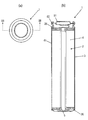
- FIG. 1A is a plan view of a lithium ion capacitor according to an embodiment of the present invention
- FIG. 1B is a cross-sectional view taken along the line IB-IB in FIG. It is a figure which shows the expanded view of the electrode group used for the lithium ion capacitor of embodiment of this invention.
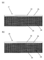
- (A) And (b) is a figure which shows the example of the positive electrode plate and negative electrode plate which are used for the lithium ion capacitor of embodiment of this invention.
- (A) And (b) is a figure which shows the example of the metallic lithium support member used for the lithium ion capacitor of embodiment of this invention.
- FIG. 1A is a plan view of the lithium ion capacitor 1 of the present embodiment with the positive electrode facing upward
- FIG. 1B is a cross-sectional view taken along the line IB-IB in FIG.
- the lithium ion capacitor 1 has a bottomed cylindrical container (can) 3 made of steel plated with nickel.
- the electrode plate group unit 2 for a lithium ion capacitor which is a combination of the electrode plate group 4, the positive electrode current collecting member 26 and the negative electrode current collecting member 36 is housed.
- the electrode plate group 4 is made of a polypropylene, a hollow cylindrical shaft core 5, a strip-like positive electrode plate 21 and a negative electrode plate 31, the first separator 6 and the second separator. 7 is wound and configured.
- a porous substrate such as kraft paper can be used as the first and second separators 6 and 7, a porous substrate such as kraft paper can be used.
- the positive electrode plate 21 is configured, for example, by coating a positive electrode active material mixture 23 on both surfaces of an aluminum foil (positive electrode current collector) 22.
- the aluminum foil includes an aluminum alloy foil.
- the positive electrode active material mixture 23 for example, a mixture of activated carbon, a binder composed of an acrylic binder, and a dispersant composed of carboxymethylcellulose (CMC) can be used.
- the aluminum foil 22 has a coating portion 24 in which a number of through-holes are formed and a positive electrode active material mixture is applied, and an uncoated portion that is formed along the longitudinal direction of the coating portion 24 and has no through-holes. It has a work part 25.
- the positive electrode active material mixture 23 is applied to the coating portion 24 with a length that is less than the length of the coating portion 24 in the width direction. That is, the uncoated portion 25 of the aluminum foil is left exposed along the coating layer of the positive electrode active material mixture 23.
- the negative electrode plate 31 also has the same structure as the positive electrode plate 21 shown in FIG. That is, as shown in FIG. 3B, the negative electrode plate 31 has a structure in which the negative electrode active material mixture 33 is applied to both surfaces of a copper foil (negative electrode current collector) 32.
- the copper foil includes not only a pure copper foil but also a copper alloy foil.
- the negative electrode active material mixture 33 for example, a mixture of amorphous carbon capable of inserting and extracting lithium ions, a binder made of polyvinylidene fluoride (PVDF), and a conductive additive such as acetylene black is used. be able to.
- the copper foil 32 has a coated part 34 in which a large number of through holes are formed, and an uncoated part 35 that is formed along the longitudinal direction of the coated part 34 and has no through holes.
- a negative electrode active material mixture 33 is applied to the coating part 34 in a length that is less than the length of the coating part 34 in the width direction. That is, the uncoated part 35 of the copper foil 32 is left exposed along the coating layer of the negative electrode active material mixture 33.
- the metal lithium support member 41 is for occluding (doping) lithium ions in the negative electrode active material (in this example, amorphous carbon) of the negative electrode plate 31.
- the metal lithium support member 41 is composed of a thin plate-like metal lithium 42, a copper foil 43, and a nickel-plated copper foil 44 (support).
- the copper foil 43 can be used by cutting the same copper foil 32 that constitutes the negative electrode plate 31 into a predetermined dimension.
- the copper foil 43 and the nickel-plated copper foil 44 are formed with a large number of through holes (not shown), and the metal lithium 42 is formed with a large number of through holes of the two supports 43 and 44. It is sandwiched between the two supports 43 and 44 so as to contact the part.
- the electrode plate group 4 has a cross section around the shaft core 5 through two separators 6 and 7 so that the positive electrode plate 21 and the negative electrode plate 31 do not directly contact each other. It is made up of a spiral.
- the positive electrode plate 21 and the negative electrode plate 31 are arranged at both ends in the width direction of the electrode plate group 4 so that the uncoated portion 25 and the uncoated portion 35 protrude outward from the separators 6 and 7.
- the winding terminal part of the electrode plate group 4 is fixed by sticking an adhesive tape across the winding terminal part and the outer peripheral surface of the electrode plate group in order to prevent unwinding.
- the positive electrode current collecting member 26 is made of aluminum (including an aluminum alloy), and has a ring shape in which a cylindrical hole 28 is formed in the center portion as shown in FIG. As shown in FIG. 1B, the hole 28 has a diameter that fits the upper end of the shaft core 5 so that the positive electrode current collecting member 26 does not deviate from the center of the electrode plate group 4.
- the positive electrode current collecting member 26 is welded to the uncoated portion 25 of the positive electrode plate 21 included in the electrode plate group 4. Therefore, as shown in FIG. 5, the positive electrode current collecting member 26 is brought closer to the electrode plate group 4 from the upper side of the electrode plate group 4 on the side where the uncoated portion 25 of the positive electrode plate 21 is located.
- the positive electrode current collecting member 26 is placed on the uncoated part 25 of the foil 22, the positive electrode current collecting member 26 is placed.
- the uncoated portion 25 and the positive electrode current collecting member 26 are welded by laser welding.
- the positive electrode current collecting member 26 is provided with four grooves 29 that are convex toward the direction in contact with the electrode plate group 4 and concave toward the direction away from the electrode plate group 4. These grooves 29 are formed by pressing, and linearly extend radially around the virtual center point of the positive electrode current collector 26.
- the positive electrode terminal part 27b welded to the positive electrode current collection member 26 in FIG. 5 is welded to the positive electrode terminal part 27a of the container lid 51 shown in FIG.
- a rubber insulating ring member 62 for electrically insulating the container 3 is attached to the outer peripheral edge of the positive electrode current collecting member 26 during assembly. .
- the negative electrode current collecting member 36 is formed of nickel or a metal material obtained by applying nickel plating to copper.
- the negative electrode current collector 36 is formed of a metal material obtained by applying nickel plating to copper.
- the negative electrode current collecting member 36 has a disk shape in which a circular depression 37 is formed in the central portion. The recess 37 is formed so as to accommodate the lower end of the shaft core 5. As shown in FIG. 5, the negative electrode current collecting member 36 is moved closer to the electrode plate group 4 from the side where the uncoated portion 35 of the copper foil 32 of the negative electrode plate 31 of the electrode plate group 4 is located. It is placed on the uncoated part 35.
- the negative electrode current collection member 36 and the uncoated part 35 of the copper foil 32 are laser-welded.
- the negative electrode current collecting member 36 is also provided with four grooves 39 that are convex toward the electrode plate group 4 and concave toward the direction away from the electrode plate group 4. These grooves 39 are formed by press working, and extend radially linearly around the virtual center point of the negative electrode current collector 36.
- Laser light is used for welding the uncoated portions 25 and 35 of the electrode plate group 4 and the current collecting members (the positive current collecting member 26 and the negative current collecting member 36).
- a direct focusing semiconductor laser device (DLL, not shown) that continuously generates laser light is used.
- the case where the negative electrode current collector 36 is welded will be described as an example.
- a direct-collecting semiconductor laser device that continuously generates laser light, the laser light is collected along the groove of the negative electrode current collector 36.
- the negative electrode current collecting member 36 is melted locally by continuously irradiating from the outer peripheral side of the electric member 36 toward the center, and the uncoated portion 35 of the copper foil 32 of the negative electrode plate and the negative electrode current collecting member 36 are Weld. A good welding result can be similarly obtained even if a fiber light guiding type semiconductor laser device is used instead of the direct focusing type semiconductor laser device.
- a metal lithium support member 41 is disposed on the outer periphery of the electrode plate group 4 to which the current collecting member is welded, that is, the electrode plate group unit 2 for a lithium ion capacitor, and is stored in the container 3 (see FIG. 1).
- the recess 37 of the negative electrode current collecting member 36 and the bottom of the container 3 are joined and electrically connected by joint welding.
- a predetermined amount of epoxy resin is injected using the inner periphery of the shaft core 5.
- the epoxy resin is solidified to fix the inner bottom portion of the container and the negative electrode current collecting member 36.
- the metallic lithium support member 41 and the side surface of the container 3 are joined by resistance welding, so that they are electrically connected to the negative electrode current collector 36 (negative electrode plate 31) through the container 3.
- the negative electrode active material in this example, amorphous carbon
- the negative electrode plate 31 can occlude (dope) lithium ions.
- An insulating ring member 62 for electrically insulating the positive current collecting member 26 and the container 3 is attached to the outer peripheral edge of the positive current collecting member 26.
- the container 3 is subjected to drawing processing in the vicinity of the opening, and the electrode group unit 2 for lithium ion capacitors is fixed in the container 3 as shown in FIG.
- a container lid 51 constituting a positive electrode terminal is disposed above the positive electrode current collecting member 26.
- the container lid 51 includes a lid body 52 disposed on the positive electrode current collector 26 and a lid cap 53 combined with the lid body 52.
- the lid main body 52 is made of aluminum, and the lid cap 53 is made of steel plated with nickel as in the case of the container 3.
- the lid cap 53 has an annular flat part 53a and a convex part 53b protruding from the center part of the flat part 53a.
- the container lid 51 is configured such that the outer peripheral portion of the flat portion 53 a of the lid cap 53 is subjected to curling processing (caulking) on the edge portion of the lid main body 52.
- a gap 54 is formed between the convex portion 53 b of the lid cap 53 and the lid body 52.
- One end of one positive electrode terminal portion 27b of the two positive electrode terminal portions 27a and 27b formed by laminating a ribbon-like aluminum foil is joined to the upper surface of the positive electrode current collecting member 26.
- One end of the other positive electrode terminal portion 27 a of the positive electrode terminal portions 27 a and 27 b is welded to a surface facing the positive electrode current collecting member 26 of the lid body 52 constituting the container lid 51. Also, the other ends of the two positive terminal portions 27a and 27b are joined together. Thereby, the lid body 52 is electrically connected to one electrode plate (positive electrode plate 21) of the electrode plate group 4.
- an annular step 3a is formed in the drawn container 3, and the container lid 51 electrically connects the container lid 51 and the container 3 on the step 3a. It arrange
- the open end 3 b of the container 3 is curled (caulked) so as to approach the container lid 51.
- the container lid 51 is fixed between the opening end portion 3b and the stepped portion 3a that are curled, with the insulating ring member 62 interposed therebetween. Thereby, the inside of the lithium ion capacitor 1 is sealed.
- ⁇ Injection of electrolyte> After injecting a nonaqueous electrolyte solution (not shown) in an amount capable of infiltrating the entire lithium ion capacitor electrode group unit 2 into the container 3, a container lid 51 is disposed at the open end 3b, and curling is performed. Process and seal.
- a nonaqueous electrolyte for example, a solution obtained by dissolving lithium hexafluorophosphate (LiPF 6 ) as an electrolyte in a solvent of propylene carbonate (PC) can be used.
- an electrolytic solution containing a specific additive is used.
- a cyclic carbonate having a double bond or a cyclic carbonate having a fluorine atom is used as an additive.
- the cyclic carbonate having a double bond include vinylene carbonate (VC) and diphenyl carbonate.
- the cyclic carbonate having a fluorine atom include fluoroethylene carbonate (FEC), fluoropropylene carbonate, fluorobutylene carbonate, and difluoroethylene carbonate.
- Example 1 Method for producing positive electrode> Weight of activated carbon having a specific surface area of 1000 m 2 / g or more as a positive electrode active material, an acrylic binder as a binder, carboxymethyl cellulose (CMC) as a dispersant, and conductive carbon powder such as acetylene black as a conductive auxiliary agent (Mass) ratio is mixed to 85: 7: 3: 5, and water (dispersion solvent) is added and kneaded to prepare a positive electrode slurry. The slurry is applied to both surfaces of an aluminum foil having a thickness of 20 ⁇ m, dried, and pressed to obtain the positive electrode plate 21.
- CMC carboxymethyl cellulose
- Mass conductive auxiliary agent
- ⁇ Method for producing negative electrode> By weight (mass) ratio of amorphous carbon capable of occluding and releasing lithium ions as a negative electrode active material, polyvinylidene fluoride (PVDF) as a binder, and conductive carbon powder such as acetylene black as a conductive additive.
- the mixture is mixed so as to be 90: 5: 5, and N-methylpyrrolidone (NMP) as a dispersion solvent is added thereto and kneaded to prepare a negative electrode slurry.
- NMP N-methylpyrrolidone
- the slurry is applied on both sides of a copper foil having a thickness of 15 ⁇ m, dried and pressed to obtain a negative electrode plate 31.
- Metal lithium 42, support 43 (same as the copper foil constituting negative electrode plate 31), and support 44 (nickel-plated copper foil) are cut into predetermined dimensions.
- the metal lithium 42 is sandwiched between the two supports 43 and 44 so as to come into contact with the portions of the two supports 43 and 44 in which many through holes are formed (see FIG. 4).
- the positive electrode plate 21 and the negative electrode plate 31 are not in direct contact via the two separators 6 and 7 with the shaft core 5 being the winding center, and the positive electrode plate 21 and the two laminates Wind so that does not come into direct contact (see FIG. 2).
- the positive electrode plate 21, the negative electrode plate 31, and the separators 6 and 7 are cut to a predetermined size so that the diameter becomes 38 mm, and along the longitudinal direction of the separators 6 and 7 wound around the outer periphery of the electrode plate group 4. Affix the adhesive tape to prevent unwinding.
- the positive electrode current collector member 26 and the negative electrode current collector member 36 are fitted to both ends of the shaft core 5, respectively, and the uncoated portion 25 of the positive electrode plate 21 and the positive electrode current collector member 26 are welded by laser welding.
- the uncoated portion 35 and the negative electrode current collecting member 36 are welded.
- a predetermined amount of epoxy resin is injected into the inner periphery of the shaft core 5, and after waiting for a predetermined time until it is solidified, the metallic lithium support member 41 and the side surface portion of the container 3 are joined by resistance welding.
- the positive electrode current collecting member 26 to which the positive electrode terminal portion 27b has been welded in advance and the container lid 51 for sealing the container 3 are joined.
- ⁇ Injection of electrolyte> A predetermined amount of non-aqueous electrolyte is injected into the container 3 using the inner circumference of the shaft core 5.
- a non-aqueous electrolyte of the present invention a solvent of propylene carbonate (PC), a solution of lithium hexafluorophosphate (LiPF 6 ) as an electrolyte at a concentration of 1.0 mol / L, and vinylene carbonate as an additive (VC) was added at 0.1 wt%.
- the addition amount of the additive in this specification is a quantity with respect to electrolyte solution.
- Example 2 A lithium ion capacitor was produced in the same manner as in Example 1 except that vinylene carbonate (VC) was added at 0.5% by weight as an additive for the electrolytic solution.
- VC vinylene carbonate
- Example 3 A lithium ion capacitor was fabricated in the same manner as in Example 1 except that vinylene carbonate (VC) was added at 1.0% by weight as an additive for the electrolytic solution.
- VC vinylene carbonate
- Example 4 A lithium ion capacitor was produced in the same manner as in Example 1 except that vinylene carbonate (VC) was added at 5% by weight as an additive for the electrolytic solution.
- VC vinylene carbonate
- Example 5 A lithium ion capacitor was produced in the same manner as in Example 1 except that vinylene carbonate (VC) was added at 10% by weight as an additive for the electrolytic solution.
- VC vinylene carbonate
- Example 6 A lithium ion capacitor was produced in the same manner as in Example 1 except that fluoroethylene carbonate (FEC) was added at 0.1% by weight as an additive for the electrolytic solution.
- FEC fluoroethylene carbonate
- Example 7 A lithium ion capacitor was produced in the same manner as in Example 1 except that fluoroethylene carbonate (FEC) was added at 0.5% by weight as an additive for the electrolytic solution.
- FEC fluoroethylene carbonate
- Example 8 A lithium ion capacitor was produced in the same manner as in Example 1 except that fluoroethylene carbonate (FEC) was added at 1.0% by weight as an additive for the electrolytic solution.
- FEC fluoroethylene carbonate
- Example 9 A lithium ion capacitor was produced in the same manner as in Example 1 except that fluoroethylene carbonate (FEC) was added at 5.0% by weight as an additive for the electrolytic solution.
- FEC fluoroethylene carbonate
- Example 10 A lithium ion capacitor was produced in the same manner as in Example 1 except that fluoroethylene carbonate (FEC) was added at 10% by weight as an additive for the electrolytic solution.
- FEC fluoroethylene carbonate
- Example 2 A lithium ion capacitor was produced in the same manner as in Example 1 except that vinylene carbonate (VC) was added at 50% by weight as an additive for the electrolytic solution.
- VC vinylene carbonate
- Example 3 A lithium ion capacitor was produced in the same manner as in Example 1 except that vinylene carbonate (VC) was added at 75% by weight as an additive for the electrolytic solution.
- VC vinylene carbonate
- Example 4 A lithium ion capacitor was produced in the same manner as in Example 1 except that fluoroethylene carbonate (FEC) was added at 50% by weight as an additive for the electrolytic solution.
- FEC fluoroethylene carbonate
- Example 5 A lithium ion capacitor was manufactured in the same manner as in Example 1 except that fluoroethylene carbonate (FEC) was added at 75% by weight as an additive for the electrolytic solution.
- FEC fluoroethylene carbonate
- ⁇ Characteristic measurement> The battery was charged with a constant current of 10 A until the cell voltage of the lithium ion capacitor reached 3.8 V, and then a constant current-constant voltage charge for applying a constant voltage of 3.8 V was performed for 30 minutes. Next, the battery was discharged at a constant current of 10 A until the cell voltage reached 2.2V. The discharge capacity and DC internal resistance of the cell in this discharge were measured.
- the discharge capacity was obtained by integrating the discharge current and the discharge time.
- DC internal resistance is obtained by approximating a straight line from the voltage 1 second and 2 seconds after the start of discharge, and the voltage drop at the start is obtained by extrapolation of this straight line, and this voltage drop is obtained by dividing it by the discharge current. It was.
- Capacity retention rate (%) (discharge capacity after test / discharge capacity before test) ⁇ 100 The rate of change in DC internal resistance was calculated by the following formula.
- Rate of change (%) (DC internal resistance after test / DC internal resistance before test) ⁇ 100
- Table 1 and FIG. 7 show the results of lithium ion capacitors in which vinylene carbonate (VC) is applied to the additive of the present invention, that is, Examples 1 to 5 and Comparative Examples 1 to 3.
- Table 2 and FIG. 8 show the results of lithium ion capacitors in which fluoroethylene carbonate (FEC) is applied to the additive of the present invention, that is, Examples 6 to 10, Comparative Examples 1, 4 and 5. Show.
- Examples 1 to 5 in which vinylene carbonate (VC) is added are compared with the direct current internal resistance value of Comparative Example 1 in which vinylene carbonate (VC) is not added. The value was small, and the rate of change after the float test was also small. In Comparative Examples 2 and 3, the DC internal resistance value before the float test was small, but the rate of change after the float test was large. As a cause of this, vinylene carbonate (VC) is decomposed on the electrode surface by charging, and the decomposition product forms a stable coating layer. The rate is thought to have declined.
- FIG. 7 is a line graph showing the relationship between the amount of vinylene carbonate (VC) added and the discharge capacity retention rate estimated from Table 1, and the relationship between the amount added and the rate of change in DC internal resistance. From FIG. 7, it can be seen that the amount of vinylene carbonate (VC) added is preferably in the range of 0.1 to 20% by weight, more preferably 0.5 to 10% by weight.
- Examples 6 to 10 in which fluoroethylene carbonate (FEC) is added are compared with the DC internal resistance values of Comparative Example 1 in which fluoroethylene carbonate (FEC) is not added And the value became small and the rate of change after a float test also became small similarly.
- Comparative Example 4 and Comparative Example 5 the DC internal resistance value before the float test was small, but the rate of change after the float test was large. The cause of this is thought to be the same as in the case of vinylene carbonate (VC), and the increase in the amount of addition resulted in an increase in the thickness of the coating layer on the electrode surface, and thus the conductivity was thought to have decreased.
- VC vinylene carbonate
- FIG. 8 is a line graph showing the relationship between the addition amount of fluoroethylene carbonate (FEC) estimated from Table 2 and the discharge capacity retention rate, and the relationship between the addition amount and the rate of change in DC internal resistance.
- FIG. 8 shows that the amount of fluoroethylene carbonate (FEC) added is preferably in the range of 0.1 to 30% by weight, more preferably 0.5 to 10% by weight.
- the present invention it is possible to obtain a lithium ion capacitor having a small internal resistance, a high discharge capacity, and an excellent long life.
Landscapes
- Engineering & Computer Science (AREA)
- Power Engineering (AREA)
- Chemical & Material Sciences (AREA)
- Microelectronics & Electronic Packaging (AREA)
- Chemical Kinetics & Catalysis (AREA)
- Electrochemistry (AREA)
- Materials Engineering (AREA)
- Electric Double-Layer Capacitors Or The Like (AREA)
- Secondary Cells (AREA)
Abstract
内部抵抗が小さくて放電容量が高く、かつ長寿命に優れたリチウムイオンキャパシタを提供する。アルミニウム箔に正極活物質合剤が塗着された正極板と、銅箔に負極活物質合剤が塗着された負極板とが、セパレータを介して積層された積層体を捲回してなる極板群と、金属リチウムとを有するリチウムイオンキャパシタ1を構成する。さらに、電解質として六フッ化リン酸リチウム(LiPF6)を含有し、添加剤として二重結合を有する環状カーボネイト、またはフッ素原子を有する環状カーボネイトを含有する電解液を用いる。
Description
本発明は、リチウムイオンキャパシタ用電解液、及びこれを含むリチウムイオンキャパシタに関するものである。
大容量キャパシタ(例えば、500F以上)として、リチウムイオン二次電池の利点と電気二重層キャパシタの利点とを組み合わせたリチウムイオンキャパシタが開発されている。最近開発が進められているリチウムイオンキャパシタは、一般に、正極活物質に活性炭、負極活物質にリチウムイオンを吸蔵・放出可能な炭素材が用いられている。リチウムイオンキャパシタは、予め負極板にリチウムイオンが吸蔵またはドープされていることにより、負極電位が通常の電気二重層キャパシタ(およそ-1V~-1.35V)より低く保たれる(およそ-3V)。そのため、セルの使用電圧範囲を高くすることができ(およそ2.2V~3.8V)、また、正極充放電機構として、通常の電気二重層キャパシタで利用される陰イオンの吸着に加え、陽イオンの吸着も利用できるため、原理的に倍の容量を取り出すことができる。
さらにリチウムイオンキャパシタは、リチウムイオン二次電池に比べて容量は小さいものの、内部抵抗が小さく出力特性の点で優れるとともに、長寿命であるという利点がある。この種のリチウムイオンキャパシタでは、電解液の電解質として種々のものを用いている。例えば、特開2010-141217号公報(特許文献1)では、電解質として六フッ化リン酸リチウム(LiPF6)を用いている。
しかしながら、顧客の要求を満たすためや他社との差別化を図るためには、さらなる特性の向上が必要である。その方法の一つとして電解液の改良が挙げられ、特定の添加剤を含有することが多い。例えば、特開2011-171293号公報(特許文献2)には、イオン性化合物を電解液に添加することによって、高電圧下でも安定に作動するリチウムイオンキャパシタが開示されている。
リチウムイオンキャパシタは、正極活物質に活性炭を使用しており、正極活物質にリチウム含有金属酸化物を使用するリチウムイオン二次電池とは大きく異なっている。つまり、リチウムイオン二次電池は、正極活物質中のリチウムが脱離・吸蔵することにより充放電が可能となるため、充放電を繰り返すと正極活物質の結晶構造が不安定となる。一方、リチウムイオンキャパシタの充放電では、正極活物質の活性炭表面上でリチウムイオンの脱離・吸着が起きている。
またリチウムイオンキャパシタは、容器内にあらかじめ負極と電気的に接続されたリチウムを配置しているため、外部印加電圧をかけなくても、正負極が電解液で浸漬されると同時に起電力を生じるという点で、リチウムイオン二次電池と大きく異なっている。
さらに、リチウムイオンキャパシタ用電解液の溶媒として、環状カーボネイトのみを使用することが可能である。例えば、環状カーボネイトであるプロピレンカーボネイト(PC)は、誘電率は高いものの粘度は高い。一方、例えば非環状カーボネイトであるジメチルカーボネイト(DMC)は、誘電率は低いものの粘度は低い。そのため、リチウムイオン二次電池用電解液の溶媒では、環状カーボネイトと非環状カーボネイトの混合溶媒を使用することが一般的である。
よって、単純にリチウムイオン二次電池で適用可能な既存技術が、そのままリチウムイオンキャパシタに適用できるとは限らず、実際には実験等で確認する必要がある。
リチウムイオンキャパシタも、高温下での充電、および充放電を繰り返して使用すると、徐々に特性の低下を生じるが、ある一定期間が経過すると急激に特性が低下する問題がある。
この原因の一つとして、一般的に六フッ化リン酸リチウム(LiPF6)を電解質に使用していることが挙げられる。六フッ化リン酸リチウム(LiPF6)は、熱安定性が高いとは言えず、60℃程度の比較的低い温度で熱分解を起こすためである。そのため、六フッ化リン酸リチウム(LiPF6)より熱安定性が高い四フッ化ホウ酸リチウム(LiBF4)を使用することも可能である。しかし、四フッ化ホウ酸リチウム(LiBF4)はリチウムの輸率が小さいため、内部抵抗が高くなり、容量も小さくなる。
本発明の目的は、内部抵抗が小さくて放電容量が高く、かつ長寿命に優れたリチウムイオンキャパシタ用電解液及びリチウムイオンキャパシタを提供することにある。
本発明のリチウムイオンキャパシタは、極板群と、金属リチウムとを有している。
極板群は、アルミニウム箔に正極活物質合剤が塗着された正極板と、銅箔に負極活物質合剤が塗着された負極板とがセパレータを介して積層した積層体を捲回して構成されている。なお、金属リチウムと、負極板と電気的に接続されてイオン透過性を有し且つ金属リチウムを保持する構造を有する金属箔からなる支持体とからなる金属リチウム支持部材を用いても良い。
そして、電解質として六フッ化リン酸リチウム(LiPF6)を含有し、添加剤として二重結合を有する環状カーボネイト、またはフッ素原子を有する環状カーボネイトを含有する電解液を用いる。
従来、電解質として用いられていた六フッ化リン酸リチウム(LiPF6)は、熱安定性が低く、60℃程度の比較的低い温度で熱分解を起こす。また、四フッ化ホウ酸リチウム(LiBF4)はリチウムの輸率が小さいため、内部抵抗が高くなり、容量も小さくなる。そこで本発明者は、電解質として六フッ化リン酸リチウム(LiPF6)を用いる場合に、添加剤として二重結合を有する環状カーボネイト、またはフッ素原子を有する環状カーボネイトを用いると、内部抵抗を小さくして放電容量を高くできることを見出した。これは、二重結合を有する環状カーボネイト、またはフッ素原子を有する環状カーボネイトは、充電により電極表面上で分解され、その分解生成物が安定な被覆層を形成するため、高温下での使用条件においても電解液の分解を抑制することができるためである。
二重結合を有する環状カーボネイトとしては、ビニレンカーボネイト(VC)を用いることができる。この場合、ビニレンカーボネイト(VC)の電解液に対する添加量は0.1~20重量%の範囲とするのが好ましい。0.1重量%を下回る場合、または20重量%を上回る場合は、内部抵抗が高くなり、放電容量は小さくなる。
フッ素原子を有する環状カーボネイトとしては、フルオロエチレンカーボネイト(FEC)を用いることができる。この場合、フルオロエチレンカーボネイト(FEC)の電解液に対する添加量は0.1~30重量%の範囲とするのが好ましい。0.1重量%と下回る場合、または30重量%を上回る場合は、内部抵抗が高くなり、放電容量は小さくなる。
本発明のリチウムイオンキャパシタ用電解液には、上記のリチウムイオンキャパシタの電解液をそのまま用いることができる。すなわち、電解質として六フッ化リン酸リチウム(LiPF6)を含有し、添加剤として二重結合を有する環状カーボネイト、またはフッ素原子を有する環状カーボネイトを含有している。
本発明のように添加剤として二重結合を有する環状カーボネイト、またはフッ素原子を有する環状カーボネイトを用いれば、添加剤が充電により電極表面上で分解され、その分解生成物が安定な被覆層を形成する。その結果、電解質として六フッ化リン酸リチウム(LiPF6)を用いても、高温下での使用条件においても電解液の分解を抑制することができるので、内部抵抗が小さくて放電容量が高く、かつ長寿命に優れたリチウムイオンキャパシタ用電解液及びリチウムイオンキャパシタを得ることができる。
以下、図面を参照して、本発明を円筒状リチウムイオンキャパシタに適用した実施の形態について説明する。
(構成)
<全体構成>
図1(a)は正極を上にした状態の本実施の形態のリチウムイオンキャパシタ1の平面図であり、(b)は図1(a)のIB-IB線断面図である。なお図1(b)には、極板群4の断面形状は図示を省略してあり、また断面部分を示すハッチングも省略してある。リチウムイオンキャパシタ1は、ニッケルメッキが施されたスチール製の有底円筒状の容器(缶)3を有している。容器3内には、極板群4と正極集電部材26及び負極集電部材36の組み合わせからなるリチウムイオンキャパシタ用極板群ユニット2が収納されている。図1(b)及び図2に示すように、極板群4は、ポリプロピレン製で中空円筒状の軸芯5に帯状の正極板21および負極板31が第1のセパレータ6及び第2のセパレータ7を介して捲回されて構成されている。第1及び第2のセパレータ6,7としては、クラフト紙等の多孔質基材を用いることができる。
<全体構成>
図1(a)は正極を上にした状態の本実施の形態のリチウムイオンキャパシタ1の平面図であり、(b)は図1(a)のIB-IB線断面図である。なお図1(b)には、極板群4の断面形状は図示を省略してあり、また断面部分を示すハッチングも省略してある。リチウムイオンキャパシタ1は、ニッケルメッキが施されたスチール製の有底円筒状の容器(缶)3を有している。容器3内には、極板群4と正極集電部材26及び負極集電部材36の組み合わせからなるリチウムイオンキャパシタ用極板群ユニット2が収納されている。図1(b)及び図2に示すように、極板群4は、ポリプロピレン製で中空円筒状の軸芯5に帯状の正極板21および負極板31が第1のセパレータ6及び第2のセパレータ7を介して捲回されて構成されている。第1及び第2のセパレータ6,7としては、クラフト紙等の多孔質基材を用いることができる。
<正極板>
正極板21は、図2及び図3(a)に示すように、例えば、アルミニウム箔(正極集電体)22の両面に、正極活物質合剤23が塗着されて構成されている。なお本願明細書において、アルミニウム箔はアルミニウム合金箔を含むものである。正極活物質合剤23としては、例えば、活性炭と、アクリル系バインダからなる結着剤と、カルボキシメチルセルロース(CMC)からなる分散剤との混合物を用いることができる。アルミニウム箔22は、多数の貫通孔が形成されて正極活物質合剤が塗布される塗工部24と、塗工部24の長手方向に沿って形成されて貫通孔が形成されていない未塗工部25を有している。塗工部24に該塗工部24の幅方向の長さに満たない長さで正極活物質合剤23が塗着されている。すなわち、正極活物質合剤23の塗布層に沿ってアルミニウム箔の未塗工部25が露出した状態で残されている。
正極板21は、図2及び図3(a)に示すように、例えば、アルミニウム箔(正極集電体)22の両面に、正極活物質合剤23が塗着されて構成されている。なお本願明細書において、アルミニウム箔はアルミニウム合金箔を含むものである。正極活物質合剤23としては、例えば、活性炭と、アクリル系バインダからなる結着剤と、カルボキシメチルセルロース(CMC)からなる分散剤との混合物を用いることができる。アルミニウム箔22は、多数の貫通孔が形成されて正極活物質合剤が塗布される塗工部24と、塗工部24の長手方向に沿って形成されて貫通孔が形成されていない未塗工部25を有している。塗工部24に該塗工部24の幅方向の長さに満たない長さで正極活物質合剤23が塗着されている。すなわち、正極活物質合剤23の塗布層に沿ってアルミニウム箔の未塗工部25が露出した状態で残されている。
<負極板>
負極板31も図3(a)に示す正極板21と同様の構造を有している。すなわち、図3(b)に示すように、負極板31は、銅箔(負極集電体)32の両面に負極活物質合剤33が塗着された構造を有している。なお本願明細書において、銅箔は、純銅箔だけでなく銅合金箔も含むものである。負極活物質合剤33としては、例えば、リチウムイオンを吸蔵・放出可能な非晶質炭素と、ポリフッ化ビニリデン(PVDF)からなる結着剤と、アセチレンブラック等の導電助材との混合物を用いることができる。銅箔32は、多数の貫通孔が形成された塗工部34と、塗工部34の長手方向に沿って形成されて貫通孔が形成されていない未塗工部35を有している。塗工部34には、該塗工部34の幅方向の長さに満たない長さで負極活物質合剤33が塗着されている。すなわち、負極活物質合剤33の塗布層に沿って銅箔32の未塗工部35が露出した状態で残されている。
負極板31も図3(a)に示す正極板21と同様の構造を有している。すなわち、図3(b)に示すように、負極板31は、銅箔(負極集電体)32の両面に負極活物質合剤33が塗着された構造を有している。なお本願明細書において、銅箔は、純銅箔だけでなく銅合金箔も含むものである。負極活物質合剤33としては、例えば、リチウムイオンを吸蔵・放出可能な非晶質炭素と、ポリフッ化ビニリデン(PVDF)からなる結着剤と、アセチレンブラック等の導電助材との混合物を用いることができる。銅箔32は、多数の貫通孔が形成された塗工部34と、塗工部34の長手方向に沿って形成されて貫通孔が形成されていない未塗工部35を有している。塗工部34には、該塗工部34の幅方向の長さに満たない長さで負極活物質合剤33が塗着されている。すなわち、負極活物質合剤33の塗布層に沿って銅箔32の未塗工部35が露出した状態で残されている。
<金属リチウム支持部材>
金属リチウム支持部材41は、負極板31の負極活物質(本例では非晶質炭素)にリチウムイオンを吸蔵(ドープ)させるためのものである。図4(a)、(b)に示すように、金属リチウム支持部材41は、薄板状の金属リチウム42と、銅箔43とニッケルメッキした銅箔44(支持体)とで構成されている。銅箔43は、負極板31を構成する銅箔32と同じものを所定寸法に切断して用いることができる。銅箔43とニッケルメッキした銅箔44には、多数の貫通孔が形成されており(図示せず)、金属リチウム42は、2枚の支持体43,44の多数の貫通孔が形成された部分に接触するようにして、2枚の支持体43,44間に挟持されている。
金属リチウム支持部材41は、負極板31の負極活物質(本例では非晶質炭素)にリチウムイオンを吸蔵(ドープ)させるためのものである。図4(a)、(b)に示すように、金属リチウム支持部材41は、薄板状の金属リチウム42と、銅箔43とニッケルメッキした銅箔44(支持体)とで構成されている。銅箔43は、負極板31を構成する銅箔32と同じものを所定寸法に切断して用いることができる。銅箔43とニッケルメッキした銅箔44には、多数の貫通孔が形成されており(図示せず)、金属リチウム42は、2枚の支持体43,44の多数の貫通孔が形成された部分に接触するようにして、2枚の支持体43,44間に挟持されている。
<極板群>
図1及び図2に示すように、極板群4は、正極板21と負極板31とが、直接接触しないように、2枚のセパレータ6,7を介して、軸芯5を中心として断面渦巻き状に捲回されて構成されている。正極板21と負極板31は、未塗工部25と未塗工部35がセパレータ6,7よりも外側に突出するように極板群4の幅方向の両端部それぞれ配置されている。なお、極板群4の捲回終端部は、捲き解けを防止するために、粘着テープを捲回終端部と極板群の外周面とに跨がって貼り付けることで固定されている。
図1及び図2に示すように、極板群4は、正極板21と負極板31とが、直接接触しないように、2枚のセパレータ6,7を介して、軸芯5を中心として断面渦巻き状に捲回されて構成されている。正極板21と負極板31は、未塗工部25と未塗工部35がセパレータ6,7よりも外側に突出するように極板群4の幅方向の両端部それぞれ配置されている。なお、極板群4の捲回終端部は、捲き解けを防止するために、粘着テープを捲回終端部と極板群の外周面とに跨がって貼り付けることで固定されている。
<正極集電部材>
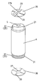
正極集電部材26は、アルミニウム(アルミニウム合金を含む)からなり、図5に示す通り、中心部分に円筒状の孔28が形成されたリング形状を有している。この孔28は図1(b)に示すように、正極集電部材26が極板群4の中心からずれないようにするために、軸芯5の上端に嵌る直径を有している。正極集電部材26は、極板群4に含まれる正極板21の未塗工部25に溶接される。そこで図5に示すように、極板群4の正極板21の未塗工部25が位置する側の上方から、正極集電部材26を極板群4に向かって近付け、正極板21のアルミニウム箔22の未塗工部25の上に、正極集電部材26を載せる。レーザ溶接により、未塗工部25と正極集電部材26とを溶接する。レーザ溶接のために、正極集電部材26には、極板群4と接する方向に向かって凸となり、極板群4から離れる方向に向かって凹となる溝29が4本設けられている。これらの溝29は、プレス加工によって形成されており、正極集電部材26の仮想中心点を中心として、放射状に直線的に延びている。なお、図5において正極集電部材26に溶接された正極端子部27bは、図6に示した容器蓋51の正極端子部27aに溶接されるものである。なお図1(b)に示すように、組立の際には、正極集電部材26の外周縁部には、容器3と電気的に絶縁するためのゴム製の絶縁リング部材62が装着される。
正極集電部材26は、アルミニウム(アルミニウム合金を含む)からなり、図5に示す通り、中心部分に円筒状の孔28が形成されたリング形状を有している。この孔28は図1(b)に示すように、正極集電部材26が極板群4の中心からずれないようにするために、軸芯5の上端に嵌る直径を有している。正極集電部材26は、極板群4に含まれる正極板21の未塗工部25に溶接される。そこで図5に示すように、極板群4の正極板21の未塗工部25が位置する側の上方から、正極集電部材26を極板群4に向かって近付け、正極板21のアルミニウム箔22の未塗工部25の上に、正極集電部材26を載せる。レーザ溶接により、未塗工部25と正極集電部材26とを溶接する。レーザ溶接のために、正極集電部材26には、極板群4と接する方向に向かって凸となり、極板群4から離れる方向に向かって凹となる溝29が4本設けられている。これらの溝29は、プレス加工によって形成されており、正極集電部材26の仮想中心点を中心として、放射状に直線的に延びている。なお、図5において正極集電部材26に溶接された正極端子部27bは、図6に示した容器蓋51の正極端子部27aに溶接されるものである。なお図1(b)に示すように、組立の際には、正極集電部材26の外周縁部には、容器3と電気的に絶縁するためのゴム製の絶縁リング部材62が装着される。
<負極集電部材>
負極集電部材36は、ニッケルまたは銅にニッケルメッキを施した金属材料のいずれかで形成されている。本実施の形態では、銅にニッケルメッキを施した金属材料で負極集電部材36を形成した。図5に示す通り、負極集電部材36は、中心部分に円形の窪み37が形成された円盤形状を有している。この窪み37は、軸芯5の下端を収納するように形成されている。図5に示す通り、負極集電部材36は、極板群4の負極板31の銅箔32の未塗工部35が位置する側から、極板群4に近付けられて、銅箔32の未塗工部35の上に載せられる。そして負極集電部材36と銅箔32の未塗工部35とはレーザ溶接される。負極集電部材36にも、正極集電部材26と同様に、極板群4に向かって凸となり極板群4から離れる方向に向かって凹となる溝39が4本設けられている。これらの溝39は、プレス加工によって形成されており、負極集電部材36の仮想中心点を中心として放射状に直線的に延びている。
負極集電部材36は、ニッケルまたは銅にニッケルメッキを施した金属材料のいずれかで形成されている。本実施の形態では、銅にニッケルメッキを施した金属材料で負極集電部材36を形成した。図5に示す通り、負極集電部材36は、中心部分に円形の窪み37が形成された円盤形状を有している。この窪み37は、軸芯5の下端を収納するように形成されている。図5に示す通り、負極集電部材36は、極板群4の負極板31の銅箔32の未塗工部35が位置する側から、極板群4に近付けられて、銅箔32の未塗工部35の上に載せられる。そして負極集電部材36と銅箔32の未塗工部35とはレーザ溶接される。負極集電部材36にも、正極集電部材26と同様に、極板群4に向かって凸となり極板群4から離れる方向に向かって凹となる溝39が4本設けられている。これらの溝39は、プレス加工によって形成されており、負極集電部材36の仮想中心点を中心として放射状に直線的に延びている。
<極板群と集電部材の溶接>
極板群4の未塗工部25及び35と集電部材(正極集電部材26及び負極集電部材36)の溶接には、レーザ光を用いる。本実施の形態では、レーザ光を連続的に発生する直接集光型半導体レーザ装置(DLL・図示せず)を用いた。負極集電部材36を溶接する場合を例にして説明すると、レーザ光を連続的に発生する直接集光型半導体レーザ装置を用いて、レーザ光を負極集電部材36の溝部に沿って負極集電部材36の外周側から中心部に向かって連続照射して負極集電部材36を局部的に溶融し、溶融金属により負極板の銅箔32の未塗工部35と負極集電部材36とを溶接する。なお、直接集光型半導体レーザ装置の代わりに、ファイバ導光型半導体レーザ装置を用いても同様に良好な溶接結果を得ることができる。
極板群4の未塗工部25及び35と集電部材(正極集電部材26及び負極集電部材36)の溶接には、レーザ光を用いる。本実施の形態では、レーザ光を連続的に発生する直接集光型半導体レーザ装置(DLL・図示せず)を用いた。負極集電部材36を溶接する場合を例にして説明すると、レーザ光を連続的に発生する直接集光型半導体レーザ装置を用いて、レーザ光を負極集電部材36の溝部に沿って負極集電部材36の外周側から中心部に向かって連続照射して負極集電部材36を局部的に溶融し、溶融金属により負極板の銅箔32の未塗工部35と負極集電部材36とを溶接する。なお、直接集光型半導体レーザ装置の代わりに、ファイバ導光型半導体レーザ装置を用いても同様に良好な溶接結果を得ることができる。
<極板群の容器への収納>
集電部材を溶接した極板群4、すなわち、リチウムイオンキャパシタ用極板群ユニット2の外周に、金属リチウム支持部材41を配置して、容器3へ収納する(図1参照)。リチウムイオンキャパシタ用極板群ユニット2を収納した状態で、負極集電部材36の窪み37と容器3の底部は、接合溶接により接合され、電気的に接続されている。
集電部材を溶接した極板群4、すなわち、リチウムイオンキャパシタ用極板群ユニット2の外周に、金属リチウム支持部材41を配置して、容器3へ収納する(図1参照)。リチウムイオンキャパシタ用極板群ユニット2を収納した状態で、負極集電部材36の窪み37と容器3の底部は、接合溶接により接合され、電気的に接続されている。
軸芯5の内周を利用して所定量のエポキシ樹脂を注入する。所定時間経過すると、このエポキシ樹脂は固化して、容器の内底部と負極集電部材36を固定する。
次に、金属リチウム支持部材41と容器3の側面部を抵抗溶接により接合することで、容器3を介して負極集電部材36(負極板31)と電気的に接続される。これにより、負極板31の負極活物質(本例では非晶質炭素)にリチウムイオンを吸蔵(ドープ)させることができる。
正極集電部材26の外周縁部には、正極集電部材26と容器3とを電気的に絶縁するための絶縁リング部材62が取り付けられている。容器3には、開口部近傍において、絞り加工が施され、図1(b)に示すように、リチウムイオンキャパシタ用極板群ユニット2は容器3内で固定される。
図6に示すように、正極集電部材26の上方には、正極端子を構成する容器蓋51が配置される。容器蓋51は、正極集電部材26の上に配置された蓋本体52と、この蓋本体52と組み合わされる蓋キャップ53とから構成されている。蓋本体52は、アルミニウムにより形成されており、蓋キャップ53は、容器3と同様にニッケルメッキが施されたスチールにより形成されている。蓋キャップ53は、環状の平坦部53aとこの平坦部53aの中央部から突出する凸部53bとを有している。容器蓋51は、蓋キャップ53の平坦部53aの外周部が蓋本体52の縁部にカーリング加工が施されて(かしめられて)構成されている。蓋キャップ53の凸部53bと蓋本体52との間には、空隙部54が形成されている。
正極集電部材26の上面には、リボン状のアルミニウム箔を積層した2本の正極端子部27a,27bのうち1本の正極端子部27bの一端が接合されている。正極端子部27a,27bのうちのもう1本の正極端子部27aの一端は、容器蓋51を構成する蓋本体52の正極集電部材26と対向する面に溶接されている。また、2本の正極端子部27a,27bの他端同士も接合される。これにより、蓋本体52は、極板群4の一方の極板(正極板21)と電気的に接続される。
上述のように、絞り加工が施された容器3には、円環状の段部3aが形成されており、容器蓋51は、段部3aの上に、容器蓋51と容器3を電気的に絶縁するための絶縁リング部材62を介して配置される。そして、容器3の開口端部3bは、容器蓋51に近づくようにカーリング加工(かしめ加工)されている。その結果、カーリング加工された開口端部3bと段部3aとの間に、容器蓋51が絶縁リング部材62を介して挟まれた状態で固定される。これにより、リチウムイオンキャパシタ1の内部は密封される。
<電解液の注入>
実際には、容器3内にリチウムイオンキャパシタ用極板群ユニット2全体を浸潤可能な量の非水電解液(不図示)を注入した後、開口端部3bに容器蓋51を配置し、カーリング加工して密封する。非水電解液には、例えばプロピレンカーボネイト(PC)の溶媒中に、電解質として6フッ化リン酸リチウム(LiPF6)を溶解した溶液を用いることができる。
実際には、容器3内にリチウムイオンキャパシタ用極板群ユニット2全体を浸潤可能な量の非水電解液(不図示)を注入した後、開口端部3bに容器蓋51を配置し、カーリング加工して密封する。非水電解液には、例えばプロピレンカーボネイト(PC)の溶媒中に、電解質として6フッ化リン酸リチウム(LiPF6)を溶解した溶液を用いることができる。
本例の電解液には、特定の添加剤を含有する電解液を用いる。具体的には、二重結合を有する環状カーボネイトやフッ素原子を有する環状カーボネイトを添加剤として用いる。二重結合を有する環状カーボネイトには、ビニレンカーボネイト(VC)、ジフェニルカーボネイトなどがある。フッ素原子を有する環状カーボネイトにはフルオロエチレンカーボネイト(FEC)、フルオロプロピレンカーボネイト、フルオロブチレンカーボネイト、ジフルオロエチレンカーボネイトなどがある。
(実施例1)
<正極の製造方法>
正極活物質として比表面積が1000m2/g以上の活性炭と、結着材としてアクリル系バインダと、分散材としてカルボキシメチルセルロース(CMC)と、導電助剤としてアセチレンブラック等の導電性炭素粉末とを重量(質量)比で85:7:3:5となるように混合し、これに水(分散溶媒)を添加、混練して正極スラリーを作製する。該スラリーを厚さ20μmのアルミニウム箔の両面に塗工し、乾燥後、プレスして正極板21を得る。
<正極の製造方法>
正極活物質として比表面積が1000m2/g以上の活性炭と、結着材としてアクリル系バインダと、分散材としてカルボキシメチルセルロース(CMC)と、導電助剤としてアセチレンブラック等の導電性炭素粉末とを重量(質量)比で85:7:3:5となるように混合し、これに水(分散溶媒)を添加、混練して正極スラリーを作製する。該スラリーを厚さ20μmのアルミニウム箔の両面に塗工し、乾燥後、プレスして正極板21を得る。
<負極の製造方法>
負極活物質としてリチウムイオンを吸蔵・放出可能な非晶質炭素と、結着材としてポリフッ化ビニリデン(PVDF)と、導電助剤としてアセチレンブラック等の導電性炭素粉末とを重量(質量)比で90:5:5となるように混合し、これに分散溶媒のN-メチルピロリドン(NMP)を添加、混練して負極スラリーを作製する。該スラリーを厚さ15μmの銅箔の両面に塗工し、乾燥後、プレスして負極板31を得る。
負極活物質としてリチウムイオンを吸蔵・放出可能な非晶質炭素と、結着材としてポリフッ化ビニリデン(PVDF)と、導電助剤としてアセチレンブラック等の導電性炭素粉末とを重量(質量)比で90:5:5となるように混合し、これに分散溶媒のN-メチルピロリドン(NMP)を添加、混練して負極スラリーを作製する。該スラリーを厚さ15μmの銅箔の両面に塗工し、乾燥後、プレスして負極板31を得る。
<金属リチウム支持部材>
金属リチウム42と、支持体43(負極板31を構成する銅箔と同じもの)と、支持体44(ニッケルメッキした銅箔)を所定寸法に切断する。金属リチウム42を2枚の支持体43,44の多数の貫通孔が形成された部分に接触するようにして、2枚の支持体43,44間に挟みこむ(図4参照)。
金属リチウム42と、支持体43(負極板31を構成する銅箔と同じもの)と、支持体44(ニッケルメッキした銅箔)を所定寸法に切断する。金属リチウム42を2枚の支持体43,44の多数の貫通孔が形成された部分に接触するようにして、2枚の支持体43,44間に挟みこむ(図4参照)。
<捲回>
極板群4は、軸芯5を捲回中心として、2枚のセパレータ6,7を介して、正極板21および負極板31が直接接触せず、かつ、正極板21と2枚の積層体が直接接触しないように捲回する(図2参照)。この時、直径が38mmになるように、正極板21、負極板31およびセパレータ6,7は所定寸法で切断され、極板群4の外周に捲回されたセパレータ6,7の長手方向に沿って、巻き解け防止の粘着テープを貼り付ける。
極板群4は、軸芯5を捲回中心として、2枚のセパレータ6,7を介して、正極板21および負極板31が直接接触せず、かつ、正極板21と2枚の積層体が直接接触しないように捲回する(図2参照)。この時、直径が38mmになるように、正極板21、負極板31およびセパレータ6,7は所定寸法で切断され、極板群4の外周に捲回されたセパレータ6,7の長手方向に沿って、巻き解け防止の粘着テープを貼り付ける。
<組立>
軸芯5の両端部にそれぞれ正極集電部材26と負極集電部材36をはめ合わせ、レーザ溶接により、正極板21の未塗工部25と正極集電部材26とを溶接し、負極板31の未塗工部35と負極集電部材36とを溶接する。この極板群4の外周に金属リチウム支持部材41を巻きつけた後、容器3内に挿入し、容器3の内底部と負極集電部材36とを抵抗溶接により接合する。
軸芯5の両端部にそれぞれ正極集電部材26と負極集電部材36をはめ合わせ、レーザ溶接により、正極板21の未塗工部25と正極集電部材26とを溶接し、負極板31の未塗工部35と負極集電部材36とを溶接する。この極板群4の外周に金属リチウム支持部材41を巻きつけた後、容器3内に挿入し、容器3の内底部と負極集電部材36とを抵抗溶接により接合する。
さらに、軸芯5の内周に所定量のエポキシ樹脂を注入し、固化するまでの所定時間待った後、金属リチウム支持部材41と容器3の側面部を抵抗溶接により接合する。
次に、あらかじめ正極端子部27bを溶接した正極集電部材26と容器3を封口するための容器蓋51を接合する。
<電解液の注入>
軸芯5の内周を利用して所定量の非水電解液を容器3内に注入する。本発明の非水電解液として、プロピレンカーボネイト(PC)の溶媒に、電解質として6フッ化リン酸リチウム(LiPF6)を1.0モル/Lの濃度で溶解した溶液に、添加剤としてビニレンカーボネイト(VC)を0.1重量%で添加した。なお、本明細書中の添加剤の添加量は電解液に対する量である。
軸芯5の内周を利用して所定量の非水電解液を容器3内に注入する。本発明の非水電解液として、プロピレンカーボネイト(PC)の溶媒に、電解質として6フッ化リン酸リチウム(LiPF6)を1.0モル/Lの濃度で溶解した溶液に、添加剤としてビニレンカーボネイト(VC)を0.1重量%で添加した。なお、本明細書中の添加剤の添加量は電解液に対する量である。
<容器の封口>
容器3にガスケット(絶縁リング部材62)をはめた後、正極端子部27aを折りたたむようにして容器蓋51で容器3に蓋をし、密封することで、リチウムイオンキャパシタを作製した。
容器3にガスケット(絶縁リング部材62)をはめた後、正極端子部27aを折りたたむようにして容器蓋51で容器3に蓋をし、密封することで、リチウムイオンキャパシタを作製した。
<負極活物質へのリチウムの吸蔵>
所定温度に管理された貯蔵室に所定期間、リチウムイオンキャパシタを放置することでリチウムイオンが負極活物質へ吸蔵され、負極が充電状態になったリチウムイオンキャパシタを得た。
所定温度に管理された貯蔵室に所定期間、リチウムイオンキャパシタを放置することでリチウムイオンが負極活物質へ吸蔵され、負極が充電状態になったリチウムイオンキャパシタを得た。
(実施例2)
電解液の添加剤として、ビニレンカーボネイト(VC)を0.5重量%で添加したこと以外、他の工程は、実施例1と同様にしてリチウムイオンキャパシタを作製した。
電解液の添加剤として、ビニレンカーボネイト(VC)を0.5重量%で添加したこと以外、他の工程は、実施例1と同様にしてリチウムイオンキャパシタを作製した。
(実施例3)
電解液の添加剤として、ビニレンカーボネイト(VC)を1.0重量%で添加したこと以外、他の工程は、実施例1と同様にしてリチウムイオンキャパシタを作製した。
電解液の添加剤として、ビニレンカーボネイト(VC)を1.0重量%で添加したこと以外、他の工程は、実施例1と同様にしてリチウムイオンキャパシタを作製した。
(実施例4)
電解液の添加剤として、ビニレンカーボネイト(VC)を5重量%で添加したこと以外、他の工程は、実施例1と同様にしてリチウムイオンキャパシタを作製した。
電解液の添加剤として、ビニレンカーボネイト(VC)を5重量%で添加したこと以外、他の工程は、実施例1と同様にしてリチウムイオンキャパシタを作製した。
(実施例5)
電解液の添加剤として、ビニレンカーボネイト(VC)を10重量%で添加したこと以外、他の工程は、実施例1と同様にしてリチウムイオンキャパシタを作製した。
電解液の添加剤として、ビニレンカーボネイト(VC)を10重量%で添加したこと以外、他の工程は、実施例1と同様にしてリチウムイオンキャパシタを作製した。
(実施例6)
電解液の添加剤として、フルオロエチレンカーボネイト(FEC)を0.1重量%で添加したこと以外、他の工程は、実施例1と同様にしてリチウムイオンキャパシタを作製した。
電解液の添加剤として、フルオロエチレンカーボネイト(FEC)を0.1重量%で添加したこと以外、他の工程は、実施例1と同様にしてリチウムイオンキャパシタを作製した。
(実施例7)
電解液の添加剤として、フルオロエチレンカーボネイト(FEC)を0.5重量%で添加したこと以外、他の工程は、実施例1と同様にしてリチウムイオンキャパシタを作製した。
電解液の添加剤として、フルオロエチレンカーボネイト(FEC)を0.5重量%で添加したこと以外、他の工程は、実施例1と同様にしてリチウムイオンキャパシタを作製した。
(実施例8)
電解液の添加剤として、フルオロエチレンカーボネイト(FEC)を1.0重量%で添加したこと以外、他の工程は、実施例1と同様にしてリチウムイオンキャパシタを作製した。
電解液の添加剤として、フルオロエチレンカーボネイト(FEC)を1.0重量%で添加したこと以外、他の工程は、実施例1と同様にしてリチウムイオンキャパシタを作製した。
(実施例9)
電解液の添加剤として、フルオロエチレンカーボネイト(FEC)を5.0重量%で添加したこと以外、他の工程は、実施例1と同様にしてリチウムイオンキャパシタを作製した。
電解液の添加剤として、フルオロエチレンカーボネイト(FEC)を5.0重量%で添加したこと以外、他の工程は、実施例1と同様にしてリチウムイオンキャパシタを作製した。
(実施例10)
電解液の添加剤として、フルオロエチレンカーボネイト(FEC)を10重量%で添加したこと以外、他の工程は、実施例1と同様にしてリチウムイオンキャパシタを作製した。
電解液の添加剤として、フルオロエチレンカーボネイト(FEC)を10重量%で添加したこと以外、他の工程は、実施例1と同様にしてリチウムイオンキャパシタを作製した。
(比較例1)
電解液に添加剤を添加しないこと以外、他の工程は、実施例1と同様にしてリチウムイオンキャパシタを作製した。
電解液に添加剤を添加しないこと以外、他の工程は、実施例1と同様にしてリチウムイオンキャパシタを作製した。
(比較例2)
電解液の添加剤として、ビニレンカーボネイト(VC)を50重量%で添加したこと以外、他の工程は、実施例1と同様にしてリチウムイオンキャパシタを作製した。
電解液の添加剤として、ビニレンカーボネイト(VC)を50重量%で添加したこと以外、他の工程は、実施例1と同様にしてリチウムイオンキャパシタを作製した。
(比較例3)
電解液の添加剤として、ビニレンカーボネイト(VC)を75重量%で添加したこと以外、他の工程は、実施例1と同様にしてリチウムイオンキャパシタを作製した。
電解液の添加剤として、ビニレンカーボネイト(VC)を75重量%で添加したこと以外、他の工程は、実施例1と同様にしてリチウムイオンキャパシタを作製した。
(比較例4)
電解液の添加剤として、フルオロエチレンカーボネイト(FEC)を50重量%で添加したこと以外、他の工程は、実施例1と同様にしてリチウムイオンキャパシタを作製した。
電解液の添加剤として、フルオロエチレンカーボネイト(FEC)を50重量%で添加したこと以外、他の工程は、実施例1と同様にしてリチウムイオンキャパシタを作製した。
(比較例5)
電解液の添加剤として、フルオロエチレンカーボネイト(FEC)を75重量%で添加したこと以外、他の工程は、実施例1と同様にしてリチウムイオンキャパシタを作製した。
電解液の添加剤として、フルオロエチレンカーボネイト(FEC)を75重量%で添加したこと以外、他の工程は、実施例1と同様にしてリチウムイオンキャパシタを作製した。
<特性測定>
10Aの定電流でリチウムイオンキャパシタのセル電圧が3.8Vになるまで充電し、その後3.8Vの定電圧を印加する定電流―定電圧充電を30分間行った。次いで、10Aの定電流でセル電圧が2.2Vになるまで放電した。この放電におけるセルの放電容量と直流内部抵抗を測定した。
10Aの定電流でリチウムイオンキャパシタのセル電圧が3.8Vになるまで充電し、その後3.8Vの定電圧を印加する定電流―定電圧充電を30分間行った。次いで、10Aの定電流でセル電圧が2.2Vになるまで放電した。この放電におけるセルの放電容量と直流内部抵抗を測定した。
放電容量は放電電流と放電時間の積算により求めた。また直流内部抵抗は、放電開始1秒後と2秒後の電圧より近似直線を求め、この直線の外挿により開始時の電圧降下分を求め、この電圧降下分を放電電流との除算により求めた。
実施例1~10および比較例1~5の方法で製造したリチウムイオンキャパシタのセルを各々10セルずつ測定して、フロート試験前後の平均値を表1および表2に示した。
<フロート試験>
80℃の恒温槽内で、5Aの定電流でリチウムイオンキャパシタのセル電圧が3.8Vになるまで充電し、その後3.8Vの定電圧を印加する定電流―定電圧充電を1000時間行った。
80℃の恒温槽内で、5Aの定電流でリチウムイオンキャパシタのセル電圧が3.8Vになるまで充電し、その後3.8Vの定電圧を印加する定電流―定電圧充電を1000時間行った。
<特性評価>
特性評価はフロート試験の前後で行い、各セルの特性変化を見た。容量維持率は、下記の式で算出した。
特性評価はフロート試験の前後で行い、各セルの特性変化を見た。容量維持率は、下記の式で算出した。
容量維持率(%)=(試験後の放電容量/試験前の放電容量)×100
直流内部抵抗の変化率は、下記の式で算出した。
直流内部抵抗の変化率は、下記の式で算出した。
変化率(%)=(試験後の直流内部抵抗/試験前の直流内部抵抗)×100
本発明の添加剤にビニレンカーボネイト(VC)を適用したリチウムイオンキャパシタ、つまり実施例1から実施例5および比較例1から比較例3の結果を表1と図7に示す。また、本発明の添加剤にフルオロエチレンカーボネイト(FEC)を適用したリチウムイオンキャパシタ、つまり実施例6から実施例10並びに比較例1,比較例4及び比較例5の結果を表2と図8に示す。

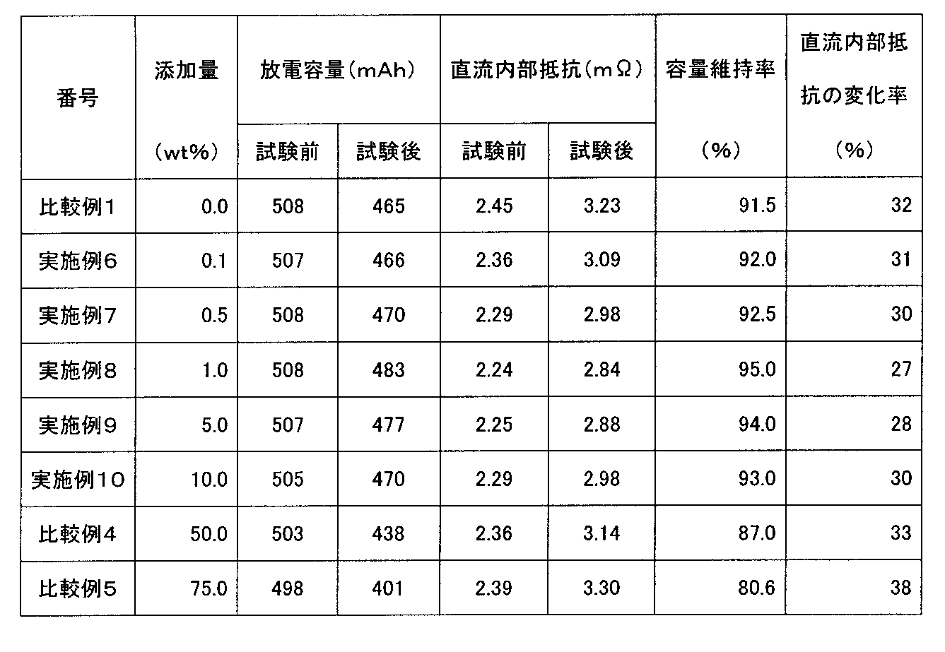
本発明の添加剤にビニレンカーボネイト(VC)を適用したリチウムイオンキャパシタ、つまり実施例1から実施例5および比較例1から比較例3の結果を表1と図7に示す。また、本発明の添加剤にフルオロエチレンカーボネイト(FEC)を適用したリチウムイオンキャパシタ、つまり実施例6から実施例10並びに比較例1,比較例4及び比較例5の結果を表2と図8に示す。
本発明の添加剤にビニレンカーボネイト(VC)を適用したリチウムイオンキャパシタにおいて、ビニレンカーボネイト(VC)を添加した実施例1から実施例5は、添加しない比較例1の直流内部抵抗値と比較して、その値は小さくなっており、フロート試験後の変化率も同様に小さくなった。比較例2と比較例3でも、フロート試験前の直流内部抵抗値は小さいが、フロート試験後の変化率は大きくなった。この原因として、ビニレンカーボネイト(VC)は、充電により電極表面上で分解され、その分解生成物が安定な被覆層を形成するが、添加量が多いことにより被覆層の厚みが大きくなったため、導電率が低下したと考えられる。
図7は、表1より推測したビニレンカーボネイト(VC)の添加量と放電容量維持率との関係および添加量と直流内部抵抗の変化率との関係を示した折れ線グラフである。図7より、ビニレンカーボネイト(VC)の添加量は、0.1~20重量%の範囲が好ましく、0.5~10重量%がより好ましいのが分かる。
本発明の添加剤にフルオロエチレンカーボネイト(FEC)を適用したリチウムイオンキャパシタにおいて、フルオロエチレンカーボネイト(FEC)を添加した実施例6から実施例10は、添加しない比較例1の直流内部抵抗値と比較して、その値は小さくなっており、フロート試験後の変化率も同様に小さくなった。比較例4と比較例5でも、フロート試験前の直流内部抵抗値は小さいが、フロート試験後の変化率は大きくなった。この原因は、ビニレンカーボネイト(VC)の場合と同様に考えられ、添加量が多いことにより電極表面上の被覆層の厚みが大きくなったため、導電率が低下したと考えられる。
図8は、表2より推測したフルオロエチレンカーボネイト(FEC)の添加量と放電容量維持率との関係および添加量と直流内部抵抗の変化率との関係を示した折れ線グラフである。図8より、フルオロエチレンカーボネイト(FEC)の添加量は、0.1~30重量%の範囲が好ましく、0.5~10重量%がより好ましいのが分かる。
本発明によれば、内部抵抗が小さくて放電容量が高く、かつ長寿命に優れたリチウムイオンキャパシタを得ることができる。
1 リチウムイオンキャパシタ
2 リチウムイオンキャパシタ用極板群ユニット
3 容器
4 極板群
5 軸芯
6 第1のセパレータ
7 第2のセパレータ
21 正極板
22 アルミニウム箔(正極集電体)
23 正極活物質合剤
24 正極板の塗工部
25 正極板の未塗工部
26 正極集電部材
27a,27b 正極端子部
31 負極板
32 銅箔(負極集電体)
33 負極活物質合剤
34 負極板の塗工部
35 負極板の未塗工部
36 負極集電部材
41 金属リチウム支持部材
42 金属リチウム
43 銅箔(支持体)
44 ニッケルメッキした銅箔(支持体)
51 容器蓋
52 蓋本体
53 蓋キャップ
54 空隙部
62 絶縁リング部材
2 リチウムイオンキャパシタ用極板群ユニット
3 容器
4 極板群
5 軸芯
6 第1のセパレータ
7 第2のセパレータ
21 正極板
22 アルミニウム箔(正極集電体)
23 正極活物質合剤
24 正極板の塗工部
25 正極板の未塗工部
26 正極集電部材
27a,27b 正極端子部
31 負極板
32 銅箔(負極集電体)
33 負極活物質合剤
34 負極板の塗工部
35 負極板の未塗工部
36 負極集電部材
41 金属リチウム支持部材
42 金属リチウム
43 銅箔(支持体)
44 ニッケルメッキした銅箔(支持体)
51 容器蓋
52 蓋本体
53 蓋キャップ
54 空隙部
62 絶縁リング部材
Claims (7)
- アルミニウム箔に正極活物質合剤が塗着された正極板と、銅箔に負極活物質合剤が塗着された負極板とが、セパレータを介して積層された積層体を捲回して構成された極板群と、
金属リチウムとを有し、
電解質として六フッ化リン酸リチウム(LiPF6)を含有し、
添加剤として二重結合を有する環状カーボネイト、またはフッ素原子を有する環状カーボネイトを含有する電解液を用いたリチウムイオンキャパシタ。 - 前記負極板と電気的に接続されてイオン透過性を有し且つ前記金属リチウムを保持する構造を有する金属箔からなる支持体を備えた請求項1に記載のリチウムイオンキャパシタ。
- 前記二重結合を有する環状カーボネイトがビニレンカーボネイト(VC)である請求項1に記載のリチウムイオンキャパシタ。
- 前記ビニレンカーボネイト(VC)の前記電解液に対する添加量が0.1~20重量%の範囲である請求項3に記載のリチウムイオンキャパシタ。
- 前記フッ素原子を有する環状カーボネイトがフルオロエチレンカーボネイト(FEC)である請求項1に記載のリチウムイオンキャパシタ。
- 前記フルオロエチレンカーボネイト(FEC)の前記電解液に対する添加量が0.1~30重量%の範囲である請求項5に記載のリチウムイオンキャパシタ。
- 電解質として六フッ化リン酸リチウム(LiPF6)を含有し、
添加剤として二重結合を有する環状カーボネイト、またはフッ素原子を有する環状カーボネイトを含有することを特徴とするリチウムイオンキャパシタ用電解液。
Priority Applications (1)
| Application Number | Priority Date | Filing Date | Title |
|---|---|---|---|
| JP2015536540A JPWO2015037486A1 (ja) | 2013-09-12 | 2014-09-03 | リチウムイオンキャパシタ用電解液及びリチウムイオンキャパシタ |
Applications Claiming Priority (2)
| Application Number | Priority Date | Filing Date | Title |
|---|---|---|---|
| JP2013189223 | 2013-09-12 | ||
| JP2013-189223 | 2013-09-12 |
Publications (1)
| Publication Number | Publication Date |
|---|---|
| WO2015037486A1 true WO2015037486A1 (ja) | 2015-03-19 |
Family
ID=52665593
Family Applications (1)
| Application Number | Title | Priority Date | Filing Date |
|---|---|---|---|
| PCT/JP2014/073154 Ceased WO2015037486A1 (ja) | 2013-09-12 | 2014-09-03 | リチウムイオンキャパシタ用電解液及びリチウムイオンキャパシタ |
Country Status (2)
| Country | Link |
|---|---|
| JP (1) | JPWO2015037486A1 (ja) |
| WO (1) | WO2015037486A1 (ja) |
Citations (6)
| Publication number | Priority date | Publication date | Assignee | Title |
|---|---|---|---|---|
| JP2006286926A (ja) * | 2005-03-31 | 2006-10-19 | Fuji Heavy Ind Ltd | リチウムイオンキャパシタ |
| JP2009187752A (ja) * | 2008-02-05 | 2009-08-20 | Fdk Corp | 蓄電素子 |
| WO2012111335A1 (ja) * | 2011-02-18 | 2012-08-23 | 三洋化成工業株式会社 | 電極保護膜形成剤 |
| JP2013020957A (ja) * | 2011-06-13 | 2013-01-31 | Nitto Denko Corp | 非水電解質蓄電デバイス及びその製造方法 |
| JP2013055285A (ja) * | 2011-09-06 | 2013-03-21 | Jm Energy Corp | 蓄電デバイス |
| JP2013062329A (ja) * | 2011-09-12 | 2013-04-04 | Fdk Corp | リチウムイオンキャパシタ |
-
2014
- 2014-09-03 JP JP2015536540A patent/JPWO2015037486A1/ja active Pending
- 2014-09-03 WO PCT/JP2014/073154 patent/WO2015037486A1/ja not_active Ceased
Patent Citations (6)
| Publication number | Priority date | Publication date | Assignee | Title |
|---|---|---|---|---|
| JP2006286926A (ja) * | 2005-03-31 | 2006-10-19 | Fuji Heavy Ind Ltd | リチウムイオンキャパシタ |
| JP2009187752A (ja) * | 2008-02-05 | 2009-08-20 | Fdk Corp | 蓄電素子 |
| WO2012111335A1 (ja) * | 2011-02-18 | 2012-08-23 | 三洋化成工業株式会社 | 電極保護膜形成剤 |
| JP2013020957A (ja) * | 2011-06-13 | 2013-01-31 | Nitto Denko Corp | 非水電解質蓄電デバイス及びその製造方法 |
| JP2013055285A (ja) * | 2011-09-06 | 2013-03-21 | Jm Energy Corp | 蓄電デバイス |
| JP2013062329A (ja) * | 2011-09-12 | 2013-04-04 | Fdk Corp | リチウムイオンキャパシタ |
Also Published As
| Publication number | Publication date |
|---|---|
| JPWO2015037486A1 (ja) | 2017-03-02 |
Similar Documents
| Publication | Publication Date | Title |
|---|---|---|
| JP5906698B2 (ja) | 非水電解質二次電池 | |
| JP4960326B2 (ja) | 二次電池 | |
| CN102057521A (zh) | 卷绕型电极组及电池 | |
| JP2011187338A (ja) | リチウムイオン二次電池 | |
| WO2014050114A1 (ja) | 非水電解質二次電池 | |
| US20260088367A1 (en) | Energy storage cell and method of manufacturing such an energy storage cell | |
| US20240178522A1 (en) | Cylindrical battery | |
| JP7209196B2 (ja) | 円筒形二次電池 | |
| JP6684034B2 (ja) | 電気化学デバイス及び電気化学デバイスの製造方法 | |
| CN111183542B (zh) | 非水电解质二次电池 | |
| JP2015070032A (ja) | リチウムイオンキャパシタ | |
| JP2011222128A (ja) | 二次電池 | |
| JP2017147367A (ja) | 電気化学デバイス及び電気化学デバイスの製造方法 | |
| JP6684035B2 (ja) | 電気化学デバイス及び電気化学デバイスの製造方法 | |
| JP5673307B2 (ja) | 非水電解質二次電池 | |
| US20240405254A1 (en) | Energy-storage element and method for producing same | |
| JP2017139324A (ja) | リチウムイオンキャパシタ | |
| JP2016126953A (ja) | 二次電池の充電ムラ低減方法及び二次電池の製造方法 | |
| JP5736914B2 (ja) | 非水電解質二次電池 | |
| JP5377472B2 (ja) | リチウムイオン二次電池 | |
| JP4548070B2 (ja) | 二次電池 | |
| JP2018032686A (ja) | リチウムイオンキャパシタ及びリチウムイオンキャパシタの製造方法 | |
| JP2008027867A (ja) | 巻回電池 | |
| JP6299125B2 (ja) | リチウムイオンキャパシタ | |
| WO2015037486A1 (ja) | リチウムイオンキャパシタ用電解液及びリチウムイオンキャパシタ |
Legal Events
| Date | Code | Title | Description |
|---|---|---|---|
| 121 | Ep: the epo has been informed by wipo that ep was designated in this application |
Ref document number: 14844028 Country of ref document: EP Kind code of ref document: A1 |
|
| ENP | Entry into the national phase |
Ref document number: 2015536540 Country of ref document: JP Kind code of ref document: A |
|
| NENP | Non-entry into the national phase |
Ref country code: DE |
|
| 122 | Ep: pct application non-entry in european phase |
Ref document number: 14844028 Country of ref document: EP Kind code of ref document: A1 |