WO2015037438A1 - 集合電池用容器 - Google Patents
集合電池用容器 Download PDFInfo
- Publication number
- WO2015037438A1 WO2015037438A1 PCT/JP2014/072371 JP2014072371W WO2015037438A1 WO 2015037438 A1 WO2015037438 A1 WO 2015037438A1 JP 2014072371 W JP2014072371 W JP 2014072371W WO 2015037438 A1 WO2015037438 A1 WO 2015037438A1
- Authority
- WO
- WIPO (PCT)
- Prior art keywords
- heater
- heaters
- series
- terminal
- container
- Prior art date
- Legal status (The legal status is an assumption and is not a legal conclusion. Google has not performed a legal analysis and makes no representation as to the accuracy of the status listed.)
- Ceased
Links
Images






Classifications
-
- H—ELECTRICITY
- H01—ELECTRIC ELEMENTS
- H01M—PROCESSES OR MEANS, e.g. BATTERIES, FOR THE DIRECT CONVERSION OF CHEMICAL ENERGY INTO ELECTRICAL ENERGY
- H01M10/00—Secondary cells; Manufacture thereof
- H01M10/60—Heating or cooling; Temperature control
- H01M10/65—Means for temperature control structurally associated with the cells
- H01M10/657—Means for temperature control structurally associated with the cells by electric or electromagnetic means
- H01M10/6571—Resistive heaters
-
- H—ELECTRICITY
- H01—ELECTRIC ELEMENTS
- H01M—PROCESSES OR MEANS, e.g. BATTERIES, FOR THE DIRECT CONVERSION OF CHEMICAL ENERGY INTO ELECTRICAL ENERGY
- H01M10/00—Secondary cells; Manufacture thereof
- H01M10/60—Heating or cooling; Temperature control
- H01M10/61—Types of temperature control
- H01M10/615—Heating or keeping warm
-
- H—ELECTRICITY
- H01—ELECTRIC ELEMENTS
- H01M—PROCESSES OR MEANS, e.g. BATTERIES, FOR THE DIRECT CONVERSION OF CHEMICAL ENERGY INTO ELECTRICAL ENERGY
- H01M10/00—Secondary cells; Manufacture thereof
- H01M10/60—Heating or cooling; Temperature control
- H01M10/65—Means for temperature control structurally associated with the cells
- H01M10/658—Means for temperature control structurally associated with the cells by thermal insulation or shielding
-
- H—ELECTRICITY
- H01—ELECTRIC ELEMENTS
- H01M—PROCESSES OR MEANS, e.g. BATTERIES, FOR THE DIRECT CONVERSION OF CHEMICAL ENERGY INTO ELECTRICAL ENERGY
- H01M50/00—Constructional details or processes of manufacture of the non-active parts of electrochemical cells other than fuel cells, e.g. hybrid cells
- H01M50/20—Mountings; Secondary casings or frames; Racks, modules or packs; Suspension devices; Shock absorbers; Transport or carrying devices; Holders
- H01M50/204—Racks, modules or packs for multiple batteries or multiple cells
- H01M50/207—Racks, modules or packs for multiple batteries or multiple cells characterised by their shape
- H01M50/213—Racks, modules or packs for multiple batteries or multiple cells characterised by their shape adapted for cells having curved cross-section, e.g. round or elliptic
-
- H—ELECTRICITY
- H01—ELECTRIC ELEMENTS
- H01M—PROCESSES OR MEANS, e.g. BATTERIES, FOR THE DIRECT CONVERSION OF CHEMICAL ENERGY INTO ELECTRICAL ENERGY
- H01M50/00—Constructional details or processes of manufacture of the non-active parts of electrochemical cells other than fuel cells, e.g. hybrid cells
- H01M50/20—Mountings; Secondary casings or frames; Racks, modules or packs; Suspension devices; Shock absorbers; Transport or carrying devices; Holders
- H01M50/218—Mountings; Secondary casings or frames; Racks, modules or packs; Suspension devices; Shock absorbers; Transport or carrying devices; Holders characterised by the material
- H01M50/22—Mountings; Secondary casings or frames; Racks, modules or packs; Suspension devices; Shock absorbers; Transport or carrying devices; Holders characterised by the material of the casings or racks
- H01M50/222—Inorganic material
- H01M50/224—Metals
-
- H—ELECTRICITY
- H01—ELECTRIC ELEMENTS
- H01M—PROCESSES OR MEANS, e.g. BATTERIES, FOR THE DIRECT CONVERSION OF CHEMICAL ENERGY INTO ELECTRICAL ENERGY
- H01M50/00—Constructional details or processes of manufacture of the non-active parts of electrochemical cells other than fuel cells, e.g. hybrid cells
- H01M50/20—Mountings; Secondary casings or frames; Racks, modules or packs; Suspension devices; Shock absorbers; Transport or carrying devices; Holders
- H01M50/271—Lids or covers for the racks or secondary casings
- H01M50/273—Lids or covers for the racks or secondary casings characterised by the material
- H01M50/276—Inorganic material
-
- H—ELECTRICITY
- H01—ELECTRIC ELEMENTS
- H01M—PROCESSES OR MEANS, e.g. BATTERIES, FOR THE DIRECT CONVERSION OF CHEMICAL ENERGY INTO ELECTRICAL ENERGY
- H01M50/00—Constructional details or processes of manufacture of the non-active parts of electrochemical cells other than fuel cells, e.g. hybrid cells
- H01M50/20—Mountings; Secondary casings or frames; Racks, modules or packs; Suspension devices; Shock absorbers; Transport or carrying devices; Holders
- H01M50/296—Mountings; Secondary casings or frames; Racks, modules or packs; Suspension devices; Shock absorbers; Transport or carrying devices; Holders characterised by terminals of battery packs
-
- H—ELECTRICITY
- H01—ELECTRIC ELEMENTS
- H01M—PROCESSES OR MEANS, e.g. BATTERIES, FOR THE DIRECT CONVERSION OF CHEMICAL ENERGY INTO ELECTRICAL ENERGY
- H01M50/00—Constructional details or processes of manufacture of the non-active parts of electrochemical cells other than fuel cells, e.g. hybrid cells
- H01M50/20—Mountings; Secondary casings or frames; Racks, modules or packs; Suspension devices; Shock absorbers; Transport or carrying devices; Holders
- H01M50/298—Mountings; Secondary casings or frames; Racks, modules or packs; Suspension devices; Shock absorbers; Transport or carrying devices; Holders characterised by the wiring of battery packs
-
- H—ELECTRICITY
- H01—ELECTRIC ELEMENTS
- H01M—PROCESSES OR MEANS, e.g. BATTERIES, FOR THE DIRECT CONVERSION OF CHEMICAL ENERGY INTO ELECTRICAL ENERGY
- H01M50/00—Constructional details or processes of manufacture of the non-active parts of electrochemical cells other than fuel cells, e.g. hybrid cells
- H01M50/50—Current conducting connections for cells or batteries
- H01M50/502—Interconnectors for connecting terminals of adjacent batteries; Interconnectors for connecting cells outside a battery casing
- H01M50/505—Interconnectors for connecting terminals of adjacent batteries; Interconnectors for connecting cells outside a battery casing comprising a single busbar
-
- H—ELECTRICITY
- H01—ELECTRIC ELEMENTS
- H01M—PROCESSES OR MEANS, e.g. BATTERIES, FOR THE DIRECT CONVERSION OF CHEMICAL ENERGY INTO ELECTRICAL ENERGY
- H01M50/00—Constructional details or processes of manufacture of the non-active parts of electrochemical cells other than fuel cells, e.g. hybrid cells
- H01M50/50—Current conducting connections for cells or batteries
- H01M50/502—Interconnectors for connecting terminals of adjacent batteries; Interconnectors for connecting cells outside a battery casing
- H01M50/509—Interconnectors for connecting terminals of adjacent batteries; Interconnectors for connecting cells outside a battery casing characterised by the type of connection, e.g. mixed connections
- H01M50/51—Connection only in series
-
- Y—GENERAL TAGGING OF NEW TECHNOLOGICAL DEVELOPMENTS; GENERAL TAGGING OF CROSS-SECTIONAL TECHNOLOGIES SPANNING OVER SEVERAL SECTIONS OF THE IPC; TECHNICAL SUBJECTS COVERED BY FORMER USPC CROSS-REFERENCE ART COLLECTIONS [XRACs] AND DIGESTS
- Y02—TECHNOLOGIES OR APPLICATIONS FOR MITIGATION OR ADAPTATION AGAINST CLIMATE CHANGE
- Y02E—REDUCTION OF GREENHOUSE GAS [GHG] EMISSIONS, RELATED TO ENERGY GENERATION, TRANSMISSION OR DISTRIBUTION
- Y02E60/00—Enabling technologies; Technologies with a potential or indirect contribution to GHG emissions mitigation
- Y02E60/10—Energy storage using batteries
Definitions
- the present invention relates to a container for an assembled battery for housing the assembled battery.
- a heat insulating container constituting an assembly battery container of a sodium-sulfur battery (hereinafter referred to as a NaS battery) as a high-temperature secondary battery is composed of a container body having an upper opening and a lid body fitted into the opening. It consists of and.
- a heat insulating container an assembled battery in which a large number of single cells are connected in a predetermined arrangement is accommodated. Electrodes are provided through one side and the other side of the heat insulating container, and these electrodes are connected to both ends of the battery assembly.
- this NaS battery operates at about 300 ° C., it is necessary to raise the temperature to that temperature, and it is also necessary to maintain the operating temperature to charge and discharge the battery. In addition, it is necessary to make the temperature distribution in the heat insulating container uniform in order to fully draw out the cell characteristics. For this reason, an electric heater is installed at the bottom of the heat insulating container, and the temperature inside the heat insulating container is controlled by the heater (see Japanese Patent Application Laid-Open Nos. 6-283215 and 8-78051).
- An object of the present invention is to provide a container for an assembled battery that can also detect a failure due to disconnection of a heater or a disconnection of a heater wire due to a failure of a single battery at an early stage.
- a container for an assembled battery according to the present invention has an opening on an upper surface thereof, a box body in which the assembled battery is stored, a lid body that closes the opening of the box body, and a container body that is installed in the box body
- a plurality of heater sections, and among the plurality of heater sections, a plurality of heaters constituting at least one heater section are connected in series.
- the heater units of the plurality of systems include a first heater unit installed at a bottom of the box and a second heater unit installed on a side wall of the box, A plurality of heaters constituting at least one heater portion among one heater portion and the second heater portion may be connected in series.
- a plurality of heaters constituting the first heater unit may be connected in series, and a plurality of heaters constituting the second heater unit may be connected in series.
- the plurality of heaters constituting each of the plurality of system heaters includes a heater wire wired in the box, a + side heater wire connected to a + terminal of the heater wire, And a negative heater wiring connected to the negative terminal of the heater wire.
- the heater unit having a plurality of heaters connected in series among the heater units of the plurality of systems is connected in series with the + side heater wiring of the heater located at one end of the series connection.
- the negative heater wiring of the heater located at the other end of the heater may be connected to a power source.
- a terminal block installed outside the box body, the terminal block corresponding to each of the heaters, and a plurality of + side connection terminals to which the + side heater wiring is connected, respectively.
- a plurality of -side connection terminals to which the -side heater wiring is connected respectively, and a + side connection terminal and the -side connection respectively corresponding to the plurality of heaters connected in series One or more jumper wires that electrically connect the terminals may be included.
- the terminal block has a + side power terminal connected to the + terminal of the power source and a ⁇ side power terminal connected to the ⁇ terminal of the power source.
- the + side connection terminal to which the + side heater wiring of the heater located at one end of the series connection is connected and the + side power supply terminal are electrically connected and connected in series.
- the -side connection terminal to which the -side heater wiring of the heater located at the other end of the series connection is connected and the -side power supply terminal are electrically connected. Also good.
- the wiring route can be simplified, the efficiency of wiring work can be improved, and the life of the heater wire can be extended, and the heater It is also possible to detect a failure due to a wire breakage or a heater wire breakage due to a cell failure early.
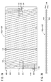
- FIG. 7A is a plan view showing the heater as viewed from above, and FIG. 7B is a front view of the heater.
- FIG. 7B is a front view of the heater.
- FIG. 8A is a plan view showing a state in which the heater wire is inserted into the insertion hole of the insulating interval holding plate as viewed from above
- FIG. 8B is a plan view showing a state in which the heater wire is supported by the support hole as seen from above.
- FIG. 9A is a plan view showing a state in which the heater wire is connected to the terminal board as viewed from above
- FIG. 9B is a plan view showing a part of FIG. 9A in an enlarged manner.
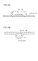
- FIG. 10A is a cross-sectional view showing a portion where a heater wire is fixed by caulking
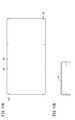
- FIG. FIG. 11A is a plan view showing the insulating thin plate as viewed from above
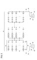
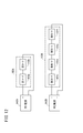
- 11B is a front view showing the mounting bracket. It is an equivalent circuit diagram which shows the wiring form of a 1st heater part and a 2nd heater part. It is a figure which shows the connection relation of the heater wiring from the 1st heater-the 6th heater in this Embodiment, and the connection terminal of a terminal block, a power supply terminal, and a jumper wire. It is an equivalent circuit diagram which shows the wiring form of the 1st heater part in a comparative example, and a 2nd heater part.
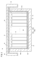
- the assembled battery container 10 has a substantially rectangular shape when viewed from above, and is, for example, a vacuum insulation design specification placed on a base 12 made of, for example, steel as shown in FIG. And a lid body 16 having, for example, atmospheric heat insulation design specifications for closing the opening of the box body 14.
- an assembled battery 20 made up of a large number of single cells 18 is accommodated in the box body 14.
- the unit cell 18 has, for example, a cylindrical shape, and is accommodated in the box body 14 with the axial direction facing the vertical direction.
- quartz sand is filled in the gap between the box body 14 and the assembled battery 20 as fire extinguishing sand so as to cope with damage to the unit cell 18, abnormal heating, or leakage of the active material.
- the box body 14 has a shape close to a rectangular parallelepiped, for example, has four side walls and a bottom wall, and has an upper surface opening.
- the box body 14 is made of, for example, a plate material made of stainless steel, and is formed in a box shape having a hollow portion 22 itself.
- the hollow portion 22 is a hermetically sealed space, and has a structure in which the hollow portion 22 and the external space can communicate with each other by a vacuum valve (not shown).
- the hollow portion 22 is loaded with a porous vacuum heat insulation board 24 in which glass fibers are solidified into a plate shape with an adhesive, and the box body 14 has a vacuum heat insulation structure.
- the lid body 16 includes a ceiling wall 26 and a wall 28 and is installed so as to close the upper surface opening of the box body 14.
- the lid 16 is made of a plate material made of, for example, stainless steel like the box 14.
- a heat insulating material layer (not shown) for obtaining a necessary minimum heat insulating property is disposed on the inner surface side (lower surface side).
- the hollow portion 30 is filled with at least two or more removable heat insulating plates 32.
- the assembled battery container 10 has only the lid 16 (upper surface) having an air insulation structure, and the amount of heat released from the upper surface of the assembled battery container 10 can be controlled.
- the cover 16 may adopt a vacuum heat insulating structure similarly to the box 14.
- the positive electrode bus bar 36 which comprises a positive electrode external terminal, and the negative electrode external terminal are comprised in the outer surface (one outer surface) of the front 1st side wall 34a among four side walls.
- a negative electrode bus bar 38 is installed.
- the assembled battery 20 includes two or more blocks 44 connected in series from the positive electrode 40 toward the negative electrode 42.
- Each block 44 is configured by connecting in parallel two or more circuits (strings 46) in which two or more single cells 18 are connected in series.
- the positive electrode 40 includes a positive electrode bus bar 36 constituting a positive electrode external terminal and a positive electrode bus 48 which is a relay member.
- the positive electrode bus 48 includes a positive electrode current collector 50, a positive electrode extension 52 and a positive electrode pole 54.
- the negative electrode 42 includes a negative electrode bus bar 38 that constitutes a negative electrode external terminal and a negative electrode bus 56 that is a relay member.
- the negative electrode bus 56 includes a negative electrode current collector 58, a negative electrode extension 60, and a negative electrode pole 62.
- the positive electrode current collector 50 and the positive electrode extension 52 of the positive electrode 40 are accommodated in the accommodating space of the box body 14.
- the positive pole 54 penetrates the first side wall 34a.
- the positive electrode current collector 50 and the positive electrode extension 52 are configured by bending one conductive material (for example, a metal plate) at a right angle in the middle.
- the positive electrode current collector 50 is disposed along the inner surface of the second side wall 34b, and the positive electrode extension 52 is disposed along the inner surface of the first side wall 34a.
- the positive pole 54 is coupled to the positive electrode extension 52 in the housing space of the box body 14, and is coupled to the positive electrode bus bar 36 outside the box body 14.
- the negative electrode current collector 58 and the negative electrode extension 60 are accommodated in the accommodating space.
- the negative pole 62 penetrates the first side wall 34a.
- the negative electrode current collector 58 and the negative electrode extension 60 are configured by bending one conductive material (for example, a metal plate) at a right angle in the middle.
- the negative electrode current collector 58 is disposed along the inner surface of the third side wall 34c, and the negative electrode extension 60 is disposed along the inner surface of the first side wall 34a.
- the negative pole 62 is coupled to the negative extension 60 in the accommodation space, and is coupled to the negative bus bar 38 outside the box body 14.
- the positive electrode current collector 50 and the positive electrode extension part 52, and the negative electrode current collector part 58 and the negative electrode extension part 60 described above are made of metal plates, which reduces the electrical resistance of the positive electrode bus 48 and the negative electrode bus 56. Contribute. Of course, each of the positive electrode current collector 50 and the positive electrode extension 52, and the negative electrode current collector 58 and the negative electrode extension 60 may be a combination of two or more conductive parts. Further, the positive pole 54 and the negative pole 62 each having a pole shape contributes to the suppression of heat in and out through the positive pole 54 and the negative pole 62.
- the box body 14 has a plurality of heater units 100.
- the heater units 100 of a plurality of systems include a first heater unit 100A (see FIG. 2) installed at the bottom of the box body 14 and side walls (first side wall 34a to fourth side wall 34d) of the box body 14. And a second heater portion 100B installed in the.
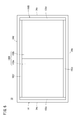
- FIG. 6 is a plan view showing the inside of the box body 14 from which the lid body 16 is removed as viewed from above, but the box body 14 is shown so that the positions of the first heater unit 100A and the second heater unit 100B can be seen. The notation of other members (the assembled battery 20 etc.) installed inside is omitted.
- the first heater section 100A has two heaters (first heater 102a and second heater 102b) juxtaposed on the bottom of the box body 14.
- the second heater unit 100B is installed along the third heater 102c installed along the first side wall 34a of the box, the fourth heater 102d installed along the second side wall 34b, and the third side wall 34c.
- the fifth heater 102e and the sixth heater 102f installed along the fourth side wall 34d.
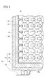
- each of the first heater 102a to the sixth heater 102f has four heater wires 106 made of nichrome wire or iron chrome wire spiraled in the width direction on the outer peripheral surface of the core member 104 made of an insulating plate. It is wound and formed into a shape.
- the core material 104 is formed of thin mica (mica).
- Mounting holes 108 are provided at a plurality of locations on the periphery of the core member 104.
- the core member 104 is formed by superposing two insulating plates 104a and 104b.
- Each heater 102a to 102f has a wide area and is thin, so that the space can be used effectively.
- the heaters 102a to 102f have good heating efficiency and excellent insulation. Even if one of the four heater wires 106 is cut, the remaining three can be heated, and the secondary battery is operated without any abnormality.
- the heater wire 106 is wound around the core material 104.
- the heat radiation amount at both ends of the long side is large. May be wound sparsely in the middle part.
- the heaters 102a to 102f have higher heat generation at both ends of the box body 14. As a result, the internal temperature of the box 14 can be made more uniform.
- the winding interval of the portion where the heater wire 106 is sparsely wound may be narrowed.
- the overall length of the heater wire 106 is increased and the electrical resistance value is increased. Therefore, the value of the current flowing through the heater wire 106 can be reduced, and the heater wire 106 is less likely to be disconnected.
- the heat distribution of the heaters 102a to 102f becomes more uniform, so that the internal temperature of the box body 14 can be made more uniform.
- the winding interval of the heater wire 106 to a value close to the diameter of the unit cell 18, when the unit cell 18 breaks down, the effect is likely to affect the heater wire 106, and the unit cell 18 malfunctions early. Can be detected.
- the insulating interval holding plate 110 has a plurality of insertion holes 112 arranged at regular intervals, and the heater wires 106 are inserted into the insertion holes 112 to prevent the heater wires 106 from being displaced.
- mutual insulation is maintained.
- the pair of terminal plates 114 (+ terminal 114a, ⁇ terminal 114b) are fixed to the core member 104, and as shown in FIG. 9A, FIG.
- a caulking fixing portion 116 that is bent in an arc shape is provided. After the end portions of the heater wires 106 are caulked to the respective caulking fixing portions 116, the end portions of the heater wires 106 are fixed to the terminal plate 114 by welding.
- the caulking portion 118 at the distal end portion of the terminal plate 114 is formed in an arc shape at the outer end of each terminal plate 114, and the heater wiring 120 (+ side heater wiring 120a, ⁇ side heater)
- the heater wiring 120 is connected to the terminal board 114 by inserting and welding the end of the wiring 120b).
- the heater wiring 120 is led out from the insertion hole 122 (hole for inserting a plurality of wirings in a hermetically sealed state) shown in FIG.
- the support hole 124 that supports the heater wire 106 is formed at one end of the core member 104, and a plurality of locking portions 126 are drilled in the side edge.
- Insulation interval holding plate 110 is also arranged on the other side wall side of core member 104 to prevent contact due to the displacement of heater wire 106 and maintain insulation.
- two insulating thin plates 128 are overlapped on both sides of the core material 104, respectively, to prevent ground faults against the active material leakage of the unit cell 18. Is secured.
- the insulating thin plate 128 is formed in a shape corresponding to the core member 104, and a plurality of mounting holes 130 are formed through the periphery thereof. Insulating thin plates 128 are disposed on both surfaces of the core member 104, and U-shaped mounting brackets 132 shown in FIG. 11B are inserted into the thin plate 128 and the mounting holes 108 of the core member 104, and the ends thereof are inserted.
- Each member is integrally formed by being bent as shown by a two-dot chain line in FIG. 11B.
- a thin aluminum heat equalizing plate 133 is disposed on the first heater 102a and the second heater 102b of the first heater unit 100A.
- the heat generated by the heater is transferred to the end of the box 14 so that the end and the intermediate are soaked, and the heat of the intermediate generated during battery operation is transmitted to the end.
- the third heater 102c to the sixth heater 102f arranged on the four side walls of the box body 14 supplementarily heat the inside of the box body 14 from the side surface, thereby further increasing the temperature inside the battery pack container 10. Increase temperature quickly and make temperature distribution uniform.
- the box body 14 includes a plurality of thermometers for measuring the temperature in the box body 14, a block voltage, etc.
- a plurality of voltmeters to measure are installed. Therefore, as shown in FIG. 1, a plurality of heater wires 120 for supplying power to the first heater 102a to the sixth heater 102f, a plurality of signal lines 134 from various voltmeters, and a plurality of signals from various thermometers
- a plurality of wirings 138 including the signal lines 136 are wired inside and outside the battery assembly 10.
- the terminal block 140 to which the plurality of wires 138 are connected is installed between the positive electrode bus bar 36 and the negative electrode bus bar 38 in the base 12. Further, a means for inserting a plurality of wires 138 between one of the positive electrode bus bar 36 and the negative electrode bus bar 38 (the positive electrode bus bar 36 in the example of FIG. 1) and the terminal block 140, in particular, a hermetically sealed state.
- the insertion hole 122 for inserting the plurality of wirings 138 is provided.
- the first heater 102a and the second heater 102b constituting the first heater unit 100A are connected in series between the + terminal and the ⁇ terminal of the first power supply 142A.
- the third heater 102c to the sixth heater 102f constituting the second heater unit 100B are connected in series between the + terminal and the ⁇ terminal of the second power supply 142B.
- a positive first heater wiring 120a1 is connected to a positive terminal 114a1 connected to one end of the first heater wire 106a.
- the first heater wire 120b1 on the negative side is connected to the negative terminal 114b1 connected to the other end of the first heater wire 106a.
- a positive heater is connected to the positive terminals 114a1 to 114a6 connected to one end of the heater wire (second heater wire 106b to sixth heater wire 106f), respectively.
- first heater wiring 120a2 to sixth heater wiring 120a6) are connected, and negative terminals 114b1 to 114b6 connected to the other end of the heater wires (second heater wire 106b to sixth heater wire 106f).
- the minus side heater wiring (the second side heater wiring 120b2 to the sixth heater wiring 120b6) is connected to the negative side.
- the terminal block 140 corresponds to the first heater 102a to the sixth heater 102f, and is connected to the six positive connection terminals (the positive side first terminal) to which the first side heater wiring 120a1 to the sixth side heater wiring 120a6 are connected.
- 6 connection terminals 144b6) are connected to the six positive connection terminals (the positive side first terminal) to which the first side heater wiring 120a1 to the sixth side heater wiring 120a6 are connected.
- the terminal block 140 includes a positive first power supply terminal 146a1 connected to the positive terminal of the first power supply 142A for the first heater section 110A and a negative side first power supply terminal connected to the negative terminal of the first power supply 142A.
- a power supply terminal 146b2 is a power supply terminal 146a1 connected to the positive terminal of the first power supply 142A for the first heater section 110A and a negative side first power supply terminal connected to the negative terminal of the first power supply 142A.
- the terminal block 140 includes a first jumper wire 148a for connecting the first heater 102a and the second heater 102b in series, and a second jumper wire for connecting the third heater 102c and the fourth heater 102d in series. 148b, a third jumper line 148c for connecting the fourth heater 102d and the fifth heater 102e in series, and a fourth jumper line 148d for connecting the fifth heater 102e and the sixth heater 102f in series. .
- first heater 102a and the second heater 102b constituting the first heater unit 100A are connected in series by the first jumper wire 148a, and the third heater 102c to the sixth heater 102f constituting the second heater unit 100B are The second jumper line 148b to the fourth jumper line 148d are connected in series.
- the terminal block 140 is a heater (for example, the first heater 102a) located at one end of the series connection of the first heater 102a and the second heater 102b connected in series constituting the first heater unit 100A.
- the + side first connection terminal 144a1 to which the + side first heater wiring 120a1 is connected and the + side first power supply terminal 146a1 are electrically connected.
- the third heater wire 120a3 on the positive side of the third heater 102c is connected to the third side on the positive side.
- the connection terminal 144a3 and the second power supply terminal 146a2 on the + side are electrically connected, and the sixth heater wiring 120b6 on the negative side of the sixth heater 102f is connected.
- the sixth connection terminal 144b6 on the negative side and the negative side The second power supply terminal 146b2 is electrically connected.
- the first heater 102a and the second heater 102b that constitute the first heater unit 100A are connected in series, and the third heater 102c to the sixth heater 102f that constitute the second heater unit 100B. Are connected in series.
- first power source 142A and second power source 142B are connected to the first heater 102a and the second heater 102b constituting the first heater unit 100A, respectively.
- the third heater 102c and the fourth heater 102d constituting the second heater unit 100B are connected in series, connected to the power source (third power source 142C), and the fifth heater 102e and the second heater unit 100B constituting the second heater unit 100B.
- the sixth heater 102f is connected in series and connected to the power supply (fourth power supply 142D).
- the power capacity is 3200 W, for example, 800 W is supplied to the first heater 102 a and the second heater 102 b, 400 W is supplied to the third heater 102 c and the fourth heater 102 d, and 400 W is supplied to the fifth heater 102 e and the sixth heater 102 f, respectively. Assume a case. At this time, if each power supply voltage of the first power supply 142A to the fourth power supply 142D is set to 200V, a current of 4A flows through the first heater 102a to the sixth heater 102f.
- the number of power supplies can be reduced.
- the first power supply 142A and the second power supply 142B are sufficient. For this reason, the wiring route is simplified, and the efficiency of wiring work can be improved.
- the power supply voltage of the first power supply 142A is set to 400V, so that the current flowing through the first heater 102a and the second heater 102b 2A is enough.
- the power supply voltage of the second power supply 142B is set to 400 V in order to apply a voltage of 100 V to the third heater 102c to the sixth heater 102f, the current flowing through the third heater 102c to the sixth heater 102f is increased. 2A is enough. In this way, since the current value can be kept low, the lifetimes of the first heater wire 106a to the sixth heater wire 106f wired to the first heater 102a to the sixth heater 102f can be extended.
- the first heater 102a By the way, for example, when a breakage occurs in the heater wire (first heater wire 106a) of the first heater 102a due to, for example, failure of the unit cell 18 (leakage of active material, etc.) or other causes, in the comparative example, the first heater
- the other second heater 102b to sixth heater 102f function as usual only by the fact that only 102a does not function. Therefore, for example, when a method of feedback controlling the temperature in the box 14 to a constant temperature based on information from a thermometer is adopted, the second heater 102b to the sixth heater 102f except the first heater 102a are used. By increasing the calorific value, the temperature in the box body 14 is maintained constant. In this case, it becomes difficult to detect a failure (such as leakage of active material) of the unit cell 18 and other failures at an early stage.
- the first heater wire 106a or the second heater wire 106b when a break occurs in the heater wire (the first heater wire 106a or the second heater wire 106b) of the first heater 102a or the second heater 102b, the first heater 102a and the second heater 102b.
- the entire first heater unit 100A including the heater 102b does not function. Therefore, it becomes difficult to maintain the temperature in the box 14 at a constant temperature, and based on the decrease in the temperature in the box 14, failure of the cell 18 (leakage of active material, etc.) and other failures are early. Can be detected.
- the wiring route can be simplified, and the efficiency of the wiring work can be improved.
- the life of the heater wire 106 can be extended, and a failure due to the disconnection of the heater wire 106 or a disconnection of the heater wire 106 due to a failure of the unit cell 18 can be detected at an early stage.
- the heater wiring 120 connected to each terminal of the first heater 102a to the sixth heater 102f is connected to a terminal block 140 installed outside the box body 14.
- the first heater 102a and the second heater 102b are connected in series, and the third heater 102c to the sixth heater 102f are connected in series.
- the plurality of heaters 102 connected in series can be arbitrarily selected by simply changing the connection position of the jumper wire 148 connected to the terminal block 140. This eliminates the need for new construction of wiring paths and wiring work, and improves the efficiency of wiring work.
- first heater unit 100A and second heater unit 100B have been mainly described, but the present invention can be easily applied to three or more heater units.
- the battery assembly container according to the present invention is not limited to the above-described embodiment, and can of course have various configurations without departing from the gist of the present invention.
Landscapes
- Chemical & Material Sciences (AREA)
- Chemical Kinetics & Catalysis (AREA)
- Electrochemistry (AREA)
- General Chemical & Material Sciences (AREA)
- Engineering & Computer Science (AREA)
- Manufacturing & Machinery (AREA)
- Inorganic Chemistry (AREA)
- Physics & Mathematics (AREA)
- Electromagnetism (AREA)
- Secondary Cells (AREA)
- Battery Mounting, Suspending (AREA)
Abstract
Description
Claims (7)
- 上面に開口を有し、集合電池(20)が収納される箱体(14)と、
前記箱体(14)の前記開口を閉塞する蓋体(16)と、
前記箱体(14)内に設置された複数系統のヒータ部(100)と、を有し、
前記複数系統のヒータ部(100)のうち、少なくとも1つの系統のヒータ部を構成する複数のヒータが直列に接続されていることを特徴とする集合電池用容器。 - 請求項1記載の集合電池用容器において、
前記複数系統のヒータ部(100)は、
前記箱体(14)の底部に設置された第1ヒータ部(100A)と、
前記箱体(14)の側壁に設置された第2ヒータ部(100B)と、を有し、
前記第1ヒータ部(100A)及び前記第2ヒータ部(100B)のうち、少なくとも1つのヒータ部を構成する複数のヒータが直列に接続されていることを特徴とする集合電池用容器。 - 請求項2記載の集合電池用容器において、
前記第1ヒータ部(100A)を構成する複数のヒータ(102a、102b)が直列に接続され、
前記第2ヒータ部(100B)を構成する複数のヒータ(102c~102f)が直列に接続されていることを特徴とする集合電池用容器。 - 請求項1~3のいずれか1項に記載の集合電池用容器において、
前記複数系統のヒータ部(100)をそれぞれ構成する複数のヒータ(102a~102f)は、
前記箱体(14)内に配線されるヒータ線(106a~106f)と、
前記ヒータ線(106a~106f)の+端子に接続された+側ヒータ配線(120a1~120a6)と、
前記ヒータ線(106a~106f)の-端子に接続された-側ヒータ配線(120b1~120b6)と、を有することを特徴とする集合電池用容器。 - 請求項4記載の集合電池用容器において、
前記複数系統のヒータ部(100)のうち、直列に接続された複数のヒータを有するヒータ部(100A、100B)は、直列接続の一方の端部に位置するヒータ(102a、102c)の前記+側ヒータ配線(120a1、120a3)と、直列接続の他方の端部に位置するヒータ(102b、102f)の前記-側ヒータ配線(120b2、120b6)とが電源(142A、142B)に接続されていることを特徴とする集合電池用容器。 - 請求項4記載の集合電池用容器において、
さらに、前記箱体(14)の外側に設置された端子台(140)を有し、
前記端子台(140)は、
各前記ヒータ(102a~102f)に対応して、それぞれ前記+側ヒータ配線(120a1~120a6)が接続される複数の+側接続端子(144a1~144a6)と、
各前記ヒータ(102a~102f)に対応して、それぞれ前記-側ヒータ配線(120b1~120b6)が接続される複数の-側接続端子(144b1~144b6)と、
直列に接続される前記複数のヒータにそれぞれ対応する前記+側接続端子と前記-側接続端子とを電気的に接続する1以上のジャンパー線(148a~148d)とを有することを特徴とする集合電池用容器。 - 請求項6記載の集合電池用容器において、
前記端子台(140)は、
電源(142A、142B)の+端子に接続された+側電源端子(146a1、146a2)と、
前記電源(142A、142B)の-端子に接続された-側電源端子(146b1、146b2)と、を有し、
直列に接続される前記複数のヒータのうち、直列接続の一方の端部に位置するヒータ(102a、102c)の前記+側ヒータ配線(120a1、120a3)が接続される前記+側接続端子(144a1、144a3)と、前記+側電源端子(146a1、146a2)とが電気的に接続され、
直列に接続される前記複数のヒータのうち、直列接続の他方の端部に位置するヒータ(102b、102f)の前記-側ヒータ配線(120b2、120b6)が接続される前記-側接続端子(144b2、144b6)と、前記-側電源端子(146b1、146b2)とが電気的に接続されていることを特徴とする集合電池用容器。
Priority Applications (4)
| Application Number | Priority Date | Filing Date | Title |
|---|---|---|---|
| CN201480050215.2A CN105531868B (zh) | 2013-09-11 | 2014-08-27 | 组合电池用容器 |
| JP2015536518A JP6283369B2 (ja) | 2013-09-11 | 2014-08-27 | 集合電池用容器 |
| EP14843259.4A EP3046177B1 (en) | 2013-09-11 | 2014-08-27 | Battery-pack case |
| US15/064,897 US10547094B2 (en) | 2013-09-11 | 2016-03-09 | Battery-pack case |
Applications Claiming Priority (2)
| Application Number | Priority Date | Filing Date | Title |
|---|---|---|---|
| JP2013188268 | 2013-09-11 | ||
| JP2013-188268 | 2013-09-11 |
Related Child Applications (1)
| Application Number | Title | Priority Date | Filing Date |
|---|---|---|---|
| US15/064,897 Continuation US10547094B2 (en) | 2013-09-11 | 2016-03-09 | Battery-pack case |
Publications (1)
| Publication Number | Publication Date |
|---|---|
| WO2015037438A1 true WO2015037438A1 (ja) | 2015-03-19 |
Family
ID=52665551
Family Applications (1)
| Application Number | Title | Priority Date | Filing Date |
|---|---|---|---|
| PCT/JP2014/072371 Ceased WO2015037438A1 (ja) | 2013-09-11 | 2014-08-27 | 集合電池用容器 |
Country Status (5)
| Country | Link |
|---|---|
| US (1) | US10547094B2 (ja) |
| EP (1) | EP3046177B1 (ja) |
| JP (1) | JP6283369B2 (ja) |
| CN (1) | CN105531868B (ja) |
| WO (1) | WO2015037438A1 (ja) |
Cited By (1)
| Publication number | Priority date | Publication date | Assignee | Title |
|---|---|---|---|---|
| WO2017044581A1 (en) * | 2015-09-09 | 2017-03-16 | General Electric Company | Heat flux assembly for an energy storage device |
Families Citing this family (7)
| Publication number | Priority date | Publication date | Assignee | Title |
|---|---|---|---|---|
| JP2016090286A (ja) * | 2014-10-30 | 2016-05-23 | 矢崎総業株式会社 | 温度検出体の取付構造 |
| KR102698844B1 (ko) * | 2018-12-04 | 2024-08-23 | 주식회사 엘지에너지솔루션 | 전지팩 |
| DE102020210306A1 (de) * | 2020-08-13 | 2022-02-17 | Robert Bosch Gesellschaft mit beschränkter Haftung | Beheiztes Batteriemodul |
| CN113054299B (zh) * | 2021-03-12 | 2022-05-31 | 安徽舟之航电池有限公司 | 一种新能源汽车用液冷集成化动力电池系统 |
| CN113644344A (zh) * | 2021-08-18 | 2021-11-12 | 武汉蔚能电池资产有限公司 | 电池包保温外壳 |
| CN114039133A (zh) * | 2021-11-30 | 2022-02-11 | 苏州中科瑞龙科技有限公司 | 一种耐低温不锈钢锂电池外壳 |
| WO2023145017A1 (ja) * | 2022-01-28 | 2023-08-03 | 日本碍子株式会社 | モジュール電池の収容容器およびモジュール電池 |
Citations (9)
| Publication number | Priority date | Publication date | Assignee | Title |
|---|---|---|---|---|
| JPS56116285A (en) * | 1980-02-15 | 1981-09-11 | Nippon Denshi Zairiyou Kk | Ceramic buried heater |
| JPS62190862A (ja) * | 1986-02-18 | 1987-08-21 | Matsushita Electronics Corp | 相補型mos集積回路の製造方法 |
| JPH0412472A (ja) * | 1990-04-27 | 1992-01-17 | Toyoda Gosei Co Ltd | バッテリ装置 |
| JPH06283215A (ja) | 1993-03-26 | 1994-10-07 | Ngk Insulators Ltd | 高温二次電池の加熱装置及び加熱方法 |
| JPH0878051A (ja) | 1994-09-08 | 1996-03-22 | Ngk Insulators Ltd | ナトリウム−硫黄電池よりなる集合電池の加熱装置及びそれを備えた集合電池並びに加熱方法 |
| JP2004047208A (ja) * | 2002-07-10 | 2004-02-12 | Ngk Insulators Ltd | 集合電池用断熱容器 |
| JP2004075103A (ja) * | 2002-08-13 | 2004-03-11 | Kawashima Packaging Mach Ltd | 包装機械用ヒータユニット及びそれを用いた包装機械用ヒータ温度制御システム |
| JP2004087430A (ja) * | 2002-08-29 | 2004-03-18 | Mitsubishi Heavy Ind Ltd | ナトリウム硫黄二次電池及び同モジュール |
| JP2005328661A (ja) * | 2004-05-14 | 2005-11-24 | Denso Corp | 回転電機のセグメント順次接合型ステータコイルおよびその製造方法 |
Family Cites Families (9)
| Publication number | Priority date | Publication date | Assignee | Title |
|---|---|---|---|---|
| DE3427028A1 (de) * | 1984-07-21 | 1986-01-23 | Eckhard 6800 Mannheim Wagner | Akkumulator |
| JPH0680594B2 (ja) | 1986-02-17 | 1994-10-12 | 株式会社ゴト− | ヒータ線を内蔵したセラミックヒータの製造方法 |
| DE60307750T2 (de) * | 2002-05-08 | 2006-12-14 | Nissan Motor Co., Ltd., Yokohama | Sekundärzellenmodul und Verfahren zu dessen Herstellung |
| JP4636815B2 (ja) * | 2004-05-26 | 2011-02-23 | 三洋電機株式会社 | 車両用の電源装置 |
| US8084154B2 (en) * | 2007-02-08 | 2011-12-27 | Karl Frederick Scheucher | Battery pack safety and thermal management apparatus and method |
| JP2010097923A (ja) * | 2008-09-16 | 2010-04-30 | Toyota Motor Corp | 蓄電装置及び車両 |
| TWM394640U (en) * | 2010-07-23 | 2010-12-11 | Exa Energy Technology Co Ltd | On-board battery with heating device |
| US8901463B2 (en) * | 2011-09-16 | 2014-12-02 | General Electric Company | Thermal management device |
| CN202395066U (zh) * | 2011-12-16 | 2012-08-22 | 日本碍子株式会社 | 容纳高温工作型电池的绝热容器和模块电池 |
-
2014
- 2014-08-27 JP JP2015536518A patent/JP6283369B2/ja active Active
- 2014-08-27 EP EP14843259.4A patent/EP3046177B1/en active Active
- 2014-08-27 WO PCT/JP2014/072371 patent/WO2015037438A1/ja not_active Ceased
- 2014-08-27 CN CN201480050215.2A patent/CN105531868B/zh active Active
-
2016
- 2016-03-09 US US15/064,897 patent/US10547094B2/en active Active
Patent Citations (9)
| Publication number | Priority date | Publication date | Assignee | Title |
|---|---|---|---|---|
| JPS56116285A (en) * | 1980-02-15 | 1981-09-11 | Nippon Denshi Zairiyou Kk | Ceramic buried heater |
| JPS62190862A (ja) * | 1986-02-18 | 1987-08-21 | Matsushita Electronics Corp | 相補型mos集積回路の製造方法 |
| JPH0412472A (ja) * | 1990-04-27 | 1992-01-17 | Toyoda Gosei Co Ltd | バッテリ装置 |
| JPH06283215A (ja) | 1993-03-26 | 1994-10-07 | Ngk Insulators Ltd | 高温二次電池の加熱装置及び加熱方法 |
| JPH0878051A (ja) | 1994-09-08 | 1996-03-22 | Ngk Insulators Ltd | ナトリウム−硫黄電池よりなる集合電池の加熱装置及びそれを備えた集合電池並びに加熱方法 |
| JP2004047208A (ja) * | 2002-07-10 | 2004-02-12 | Ngk Insulators Ltd | 集合電池用断熱容器 |
| JP2004075103A (ja) * | 2002-08-13 | 2004-03-11 | Kawashima Packaging Mach Ltd | 包装機械用ヒータユニット及びそれを用いた包装機械用ヒータ温度制御システム |
| JP2004087430A (ja) * | 2002-08-29 | 2004-03-18 | Mitsubishi Heavy Ind Ltd | ナトリウム硫黄二次電池及び同モジュール |
| JP2005328661A (ja) * | 2004-05-14 | 2005-11-24 | Denso Corp | 回転電機のセグメント順次接合型ステータコイルおよびその製造方法 |
Non-Patent Citations (1)
| Title |
|---|
| See also references of EP3046177A4 |
Cited By (4)
| Publication number | Priority date | Publication date | Assignee | Title |
|---|---|---|---|---|
| WO2017044581A1 (en) * | 2015-09-09 | 2017-03-16 | General Electric Company | Heat flux assembly for an energy storage device |
| CN108140910A (zh) * | 2015-09-09 | 2018-06-08 | 通用电气公司 | 用于储能装置的热通量组件 |
| US10333184B2 (en) | 2015-09-09 | 2019-06-25 | General Electric Company | Heat flux assembly for an energy storage device |
| CN108140910B (zh) * | 2015-09-09 | 2021-07-13 | 通用电气公司 | 用于储能装置的热通量组件 |
Also Published As
| Publication number | Publication date |
|---|---|
| US20160190666A1 (en) | 2016-06-30 |
| CN105531868B (zh) | 2018-11-02 |
| CN105531868A (zh) | 2016-04-27 |
| EP3046177A1 (en) | 2016-07-20 |
| EP3046177B1 (en) | 2018-10-17 |
| EP3046177A4 (en) | 2017-04-26 |
| JP6283369B2 (ja) | 2018-02-21 |
| JPWO2015037438A1 (ja) | 2017-03-02 |
| US10547094B2 (en) | 2020-01-28 |
Similar Documents
| Publication | Publication Date | Title |
|---|---|---|
| JP6283369B2 (ja) | 集合電池用容器 | |
| CN107112483B (zh) | 温度检测部件安装到母线的安装结构、布线模块以及布线模块的制造方法 | |
| CN102870252B (zh) | 薄形电池模块以及使用此模块的电池组 | |
| IT201800002774A1 (it) | Pacco batteria veicolare | |
| JP6083306B2 (ja) | 電池パック | |
| US20190221817A1 (en) | Battery module | |
| CN106207025B (zh) | 电的能量存储器模块和相应的模块化构造的能量存储器 | |
| CN103326082B (zh) | 电池模块 | |
| JP2013532890A (ja) | 設計および組み立てが容易なセルからなるバッテリ | |
| JP6397117B2 (ja) | 特に電気自動車のための、バッテリモジュールのバッテリセルの構成要素を支持及び保持するための支持構成 | |
| CN103180701A (zh) | 用于检测蓄能器的温度的装置 | |
| JP6090811B2 (ja) | 集合電池用容器 | |
| JP2019114389A (ja) | バッテリモジュール | |
| IT201800002771A1 (it) | Pacco batteria veicolare | |
| KR102391116B1 (ko) | 배터리 모듈 | |
| JP5902837B2 (ja) | 集合電池用容器 | |
| JP2020187978A (ja) | バスバモジュール | |
| CN105304974B (zh) | 尤其用于机动车辆的蓄电池的温度控制设备 | |
| JP2015006102A (ja) | 蓄電池システム及び蓄電池システムの制御方法 | |
| IT201800002775A1 (it) | Pacco batteria veicolare | |
| IT201800002772A1 (it) | Pacco batteria veicolare | |
| CN206076336U (zh) | 电池包 | |
| JP2025104244A (ja) | 高電圧ボックス | |
| KR20260016143A (ko) | 배터리 모듈 |
Legal Events
| Date | Code | Title | Description |
|---|---|---|---|
| WWE | Wipo information: entry into national phase |
Ref document number: 201480050215.2 Country of ref document: CN |
|
| 121 | Ep: the epo has been informed by wipo that ep was designated in this application |
Ref document number: 14843259 Country of ref document: EP Kind code of ref document: A1 |
|
| ENP | Entry into the national phase |
Ref document number: 2015536518 Country of ref document: JP Kind code of ref document: A |
|
| REEP | Request for entry into the european phase |
Ref document number: 2014843259 Country of ref document: EP |
|
| WWE | Wipo information: entry into national phase |
Ref document number: 2014843259 Country of ref document: EP |
|
| NENP | Non-entry into the national phase |
Ref country code: DE |