WO2015037367A1 - 非水電解液二次電池 - Google Patents
非水電解液二次電池 Download PDFInfo
- Publication number
- WO2015037367A1 WO2015037367A1 PCT/JP2014/070698 JP2014070698W WO2015037367A1 WO 2015037367 A1 WO2015037367 A1 WO 2015037367A1 JP 2014070698 W JP2014070698 W JP 2014070698W WO 2015037367 A1 WO2015037367 A1 WO 2015037367A1
- Authority
- WO
- WIPO (PCT)
- Prior art keywords
- negative electrode
- secondary battery
- aqueous electrolyte
- electrolyte secondary
- group
- Prior art date
- Legal status (The legal status is an assumption and is not a legal conclusion. Google has not performed a legal analysis and makes no representation as to the accuracy of the status listed.)
- Ceased
Links
Images

Classifications
-
- H—ELECTRICITY
- H01—ELECTRIC ELEMENTS
- H01M—PROCESSES OR MEANS, e.g. BATTERIES, FOR THE DIRECT CONVERSION OF CHEMICAL ENERGY INTO ELECTRICAL ENERGY
- H01M10/00—Secondary cells; Manufacture thereof
- H01M10/05—Accumulators with non-aqueous electrolyte
- H01M10/056—Accumulators with non-aqueous electrolyte characterised by the materials used as electrolytes, e.g. mixed inorganic/organic electrolytes
- H01M10/0564—Accumulators with non-aqueous electrolyte characterised by the materials used as electrolytes, e.g. mixed inorganic/organic electrolytes the electrolyte being constituted of organic materials only
- H01M10/0566—Liquid materials
- H01M10/0567—Liquid materials characterised by the additives
-
- H—ELECTRICITY
- H01—ELECTRIC ELEMENTS
- H01M—PROCESSES OR MEANS, e.g. BATTERIES, FOR THE DIRECT CONVERSION OF CHEMICAL ENERGY INTO ELECTRICAL ENERGY
- H01M10/00—Secondary cells; Manufacture thereof
- H01M10/05—Accumulators with non-aqueous electrolyte
- H01M10/052—Li-accumulators
-
- H—ELECTRICITY
- H01—ELECTRIC ELEMENTS
- H01M—PROCESSES OR MEANS, e.g. BATTERIES, FOR THE DIRECT CONVERSION OF CHEMICAL ENERGY INTO ELECTRICAL ENERGY
- H01M4/00—Electrodes
- H01M4/02—Electrodes composed of, or comprising, active material
- H01M4/04—Processes of manufacture in general
- H01M4/0438—Processes of manufacture in general by electrochemical processing
- H01M4/044—Activating, forming or electrochemical attack of the supporting material
- H01M4/0445—Forming after manufacture of the electrode, e.g. first charge, cycling
-
- H—ELECTRICITY
- H01—ELECTRIC ELEMENTS
- H01M—PROCESSES OR MEANS, e.g. BATTERIES, FOR THE DIRECT CONVERSION OF CHEMICAL ENERGY INTO ELECTRICAL ENERGY
- H01M4/00—Electrodes
- H01M4/02—Electrodes composed of, or comprising, active material
- H01M4/13—Electrodes for accumulators with non-aqueous electrolyte, e.g. for lithium-accumulators; Processes of manufacture thereof
- H01M4/133—Electrodes based on carbonaceous material, e.g. graphite-intercalation compounds or CFx
-
- H—ELECTRICITY
- H01—ELECTRIC ELEMENTS
- H01M—PROCESSES OR MEANS, e.g. BATTERIES, FOR THE DIRECT CONVERSION OF CHEMICAL ENERGY INTO ELECTRICAL ENERGY
- H01M4/00—Electrodes
- H01M4/02—Electrodes composed of, or comprising, active material
- H01M4/13—Electrodes for accumulators with non-aqueous electrolyte, e.g. for lithium-accumulators; Processes of manufacture thereof
- H01M4/139—Processes of manufacture
- H01M4/1393—Processes of manufacture of electrodes based on carbonaceous material, e.g. graphite-intercalation compounds or CFx
-
- H—ELECTRICITY
- H01—ELECTRIC ELEMENTS
- H01M—PROCESSES OR MEANS, e.g. BATTERIES, FOR THE DIRECT CONVERSION OF CHEMICAL ENERGY INTO ELECTRICAL ENERGY
- H01M4/00—Electrodes
- H01M4/02—Electrodes composed of, or comprising, active material
- H01M4/36—Selection of substances as active materials, active masses, active liquids
- H01M4/362—Composites
- H01M4/366—Composites as layered products
-
- Y—GENERAL TAGGING OF NEW TECHNOLOGICAL DEVELOPMENTS; GENERAL TAGGING OF CROSS-SECTIONAL TECHNOLOGIES SPANNING OVER SEVERAL SECTIONS OF THE IPC; TECHNICAL SUBJECTS COVERED BY FORMER USPC CROSS-REFERENCE ART COLLECTIONS [XRACs] AND DIGESTS
- Y02—TECHNOLOGIES OR APPLICATIONS FOR MITIGATION OR ADAPTATION AGAINST CLIMATE CHANGE
- Y02E—REDUCTION OF GREENHOUSE GAS [GHG] EMISSIONS, RELATED TO ENERGY GENERATION, TRANSMISSION OR DISTRIBUTION
- Y02E60/00—Enabling technologies; Technologies with a potential or indirect contribution to GHG emissions mitigation
- Y02E60/10—Energy storage using batteries
Definitions
- the present invention relates to a non-aqueous electrolyte secondary battery characterized by the relationship between the amount of water in the negative electrode and the additive in the electrolyte.
- a secondary battery using such a non-aqueous electrolyte (hereinafter referred to as a non-aqueous electrolyte secondary battery) is mainly composed of an electrode active material capable of reversibly occluding and releasing chemical species (lithium ions) as charge carriers.
- a non-aqueous electrolyte is inserted and sealed between electrodes (positive electrode and negative electrode) provided with an electrode active material layer on the electrode current collector.
- non-aqueous electrolyte secondary batteries particularly lithium ion non-aqueous electrolyte secondary batteries
- the liquid may contain about 20 ppm or more of water.
- the active material layer in the positive electrode and the negative electrode can contain moisture.
- Patent Document 1 discloses that the existence is allowed.
- the positive electrode or negative electrode active material layer is formed by adding an appropriate solvent and dispersing an active material together with a binder, applying the obtained paste or slurry to a current collector, and drying.
- As the positive electrode active material lithium manganate composite oxide and lithium iron phosphate, which are more resource-efficient than conventional lithium cobaltate composite oxides, are becoming mainstream.
- As the negative electrode active material a carbon-based negative electrode material is mainstream.
- an active material such as graphite (natural or artificial), graphitizable carbon (soft carbon), non-graphitizable carbon (hard carbon), and fibrous carbon is used as a binder ( It can be obtained by dispersing in water together with styrene-butadiene rubber (SBR) and a thickener (carboxymethyl cellulose: CMC), preparing an aqueous slurry, applying it, and drying.
- SBR styrene-butadiene rubber
- CMC carboxymethyl cellulose
- water-based thickeners such as CMC are extremely hygroscopic and require treatment at high temperatures to remove moisture to a high degree, but cracks occur in the active material layer due to the low decomposition temperature. There is.
- Patent Document 2 describes the surface of the active material layer before the formation of the porous inorganic layer in order to prevent the binder for the porous inorganic layer from covering the surface of the active material when forming the porous inorganic layer on the surface of the active material layer. It is disclosed that the water concentration of this is about 100 to 500 ppm.
- the water content of the final negative electrode sheet is 200 ppm or less, preferably 100 ppm or less.
- the negative electrode active material layer is applied, dried, and then exposed to an environment having a dew point temperature of 17 ° C. to 52 ° C. for at least 30 minutes. Drying is adjusted so that the water concentration is 500 ppm or less.
- Patent Documents 4 to 6 As a method of suppressing the decomposition reaction of the electrolytic solution by forming a protective film on the electrode surface, a technique using a secondary battery electrolytic solution containing a cyclic sulfonic acid ester having at least two sulfonyl groups, or unsaturated Techniques using a cyclic or chain disulfonic acid ester having a bond are disclosed (Patent Documents 4 to 6).
- Patent Document 7 describes a lithium ion secondary battery having an electrolytic solution containing a chain disulfonic acid ester and a cyclic disulfonic acid ester, and a negative electrode containing one type of carbon as a negative electrode active material.
- the amount of moisture in the non-aqueous electrolyte secondary battery particularly the amount of moisture in the negative electrode
- the additive in the non-aqueous electrolyte particularly the addition of a protective film to suppress SEI formation on the surface of the negative electrode active material layer
- the negative electrode active material not only the water-based negative electrode mixture described above, but also an organic solvent-based negative electrode mixture using polyvinylidene fluoride (PVdF) or the like as a binder, the negative electrode active material, the conductive material, and the organic solvent easily absorb moisture. It is often composed of materials and may contain a lot of moisture depending on the manufacturing environment.
- PVdF polyvinylidene fluoride
- the present invention focuses on the relationship between the protective film-forming additive in the non-aqueous electrolyte and the amount of moisture in the negative electrode, and an object is to provide a non-aqueous electrolyte secondary battery excellent in battery characteristics, particularly coulomb efficiency.
- R 1 and R 2 each independently represent a hydrogen atom, a halogen atom, an alkyl group having 1 to 5 carbon atoms, or an amino group, provided that at least one of R 1 and R 2 is hydrogen.
- R 3 is an alkylene group having 1 to 5 carbon atoms, a carbonyl group, a sulfinyl group, a fluoroalkylene group having 1 to 6 carbon atoms, an alkylene unit or a carbon number 2 in which a fluoroalkylene unit is bonded via an ether bond.
- a linking group selected from the group consisting of divalent groups of 6 to 6 is shown.
- the embodiment of the present invention can provide a non-aqueous electrolyte secondary battery excellent in coulomb efficiency.
- nonaqueous electrolyte solution is a cyclic represented by the general formula (1) as an additive.
- Contains a sulfonic acid ester hereinafter sometimes simply referred to as “compound of general formula (1)”.
- R 1 and R 2 each independently represent a hydrogen atom, a halogen atom, an alkyl group having 1 to 5 carbon atoms, or an amino group, provided that at least one of R 1 and R 2 is hydrogen.
- R 3 is an alkylene group having 1 to 5 carbon atoms, a carbonyl group, a sulfinyl group, a fluoroalkylene group having 1 to 6 carbon atoms, an alkylene unit or a carbon number 2 in which a fluoroalkylene unit is bonded via an ether bond.
- a linking group selected from the group consisting of divalent groups of 6 to 6 is shown.
- the cyclic sulfonate ester represented by the general formula (1) contained in the nonaqueous electrolytic solution is decomposed by an electrochemical redox reaction during the charge / discharge reaction to form a film on the surface of the negative electrode active material.
- the decomposition of the supporting salt can be suppressed. This is considered to be effective in extending the life of the lithium ion secondary battery.
- the electrolytic solution containing such a compound of the general formula (1) storage stability is improved and deterioration is suppressed, and when this electrolytic solution is used, capacity maintenance and storage characteristics of the lithium ion secondary battery, In particular, the remaining capacity maintenance characteristic accompanying self-discharge is remarkably improved.
- Cyclic sulfonic acid ester represented by the above general formula (1) is compared by either R 1, R 2 is replaced with a sulfonic acid ester both of R 1, R 2 is a hydrogen atom
- the film forming ability formed on the negative electrode surface is improved.
- the cyclic sulfonate ester represented by the general formula (1) is substituted with a compound in which either R 1 or R 2 is a hydrogen atom because either R 1 or R 2 is substituted.
- the ⁇ -position carbon substituted by R 1 and R 2 in the general formula (1) is water in the negative electrode in the case of an unsubstituted additive (in this case, R 3 is a compound of methylene and is referred to as additive X1).
- R 3 is a compound of methylene and is referred to as additive X1.
- the additive X1 adsorbed on the negative electrode surface is combined with free Li ions (formula (a)) in the electrolytic solution after hydrogen is extracted to form a Li salt and elute into the electrolytic solution.
- the ability to form a film on the surface of the negative electrode active material is reduced.
- the ⁇ -position carbon is substituted with a substituent such as a methyl group, hydrogen abstraction from the ⁇ -position carbon is suppressed, and a decrease in film forming ability is suppressed.
- a compound in which at least one of R 1 and R 2 is an alkyl group is preferable.
- Particularly preferred are compounds in which one is an alkyl group and the other is a hydrogen atom, or both are alkyl groups.
- Alkyl groups for R 1 and R 2 include methyl, ethyl, propyl, butyl and pentyl, which may be linear or branched. In particular, methyl, ethyl and propyl are preferred.
- the halogen atom include a fluorine atom, a chlorine atom, and a bromine atom, and a fluorine atom is preferable.
- R 3 represents an alkylene group having 1 to 5 carbon atoms, a carbonyl group, a sulfinyl group, a fluoroalkylene group having 1 to 6 carbon atoms, or an alkylene unit or 2 having 2 to 6 carbon atoms bonded to each other via an ether bond.
- a linking group selected from the group consisting of valent groups is shown.
- the alkylene group having 1 to 5 carbon atoms is preferably methylene, ethylene (1,1-ethylene, 1,2-ethylene) or 2,2-propylene.
- the fluoroalkylene group having 1 to 6 carbon atoms is monofluoro Methylene, difluoromethylene, monofluoroethylene, difluoroethylene, trifluoroethylene and tetrafluoroethylene are preferred.
- R 3 is preferably an alkylene group having 1 to 5 carbon atoms, a fluoroalkylene group having 1 to 6 carbon atoms, or a carbonyl group, and among them, methylene or ethylene is most preferable.
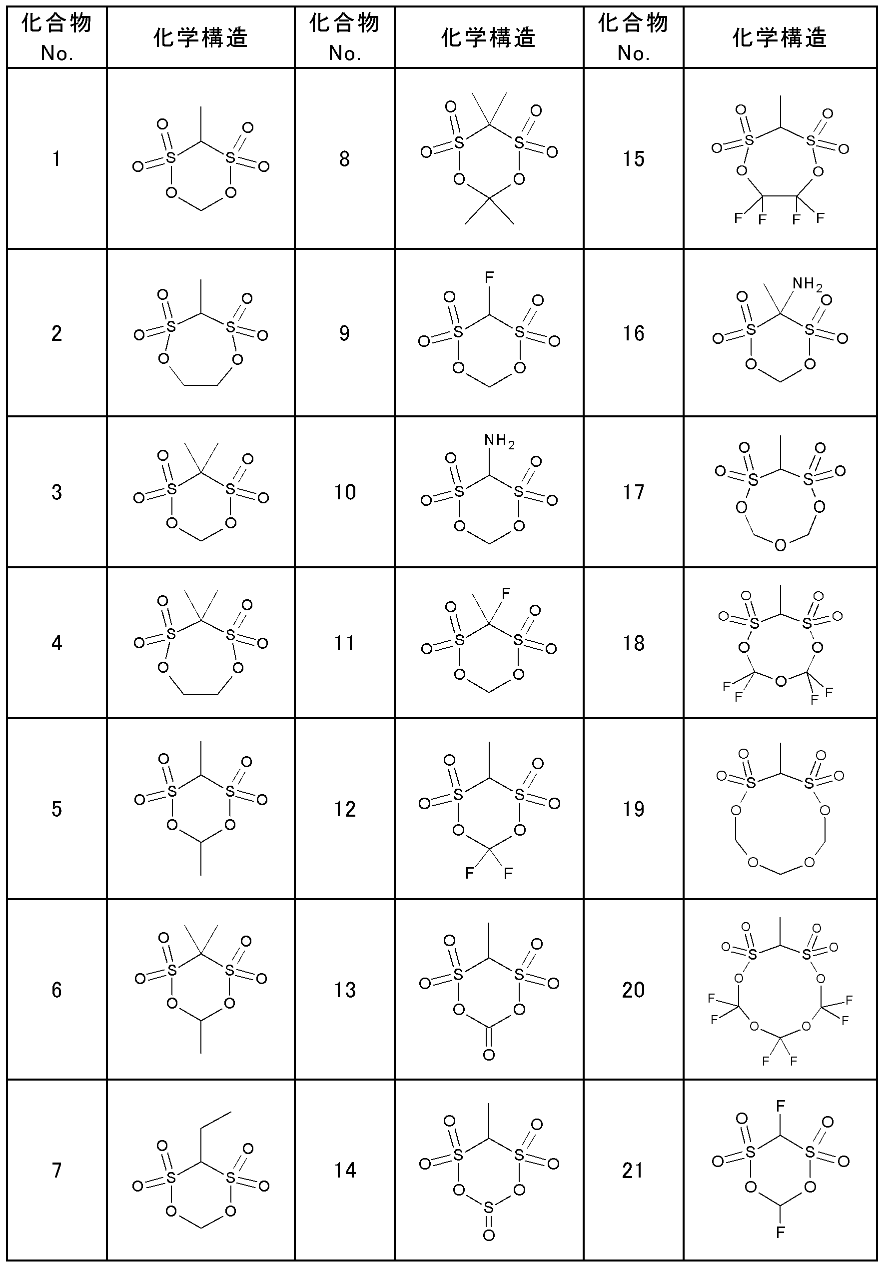
- the compounds represented by the general formula (1) may be used singly or in combination of two or more. Although the typical example of a compound of General formula (1) is specifically illustrated in Table 1, this invention is not limited to these.
- the compound of the general formula (1) is produced by, for example, a production method described in US Pat. No. 4,950,768 (Japanese Patent Laid-Open No. 61-501089, Japanese Patent Publication No. 5-44946), Japanese Patent Laid-Open No. 2005-336155, etc. Can be used.
- the proportion of the compound of the general formula (1) in the electrolytic solution is not particularly limited, but it is preferably contained in 0.005 to 10% by mass of the entire electrolytic solution.
- concentration of the compound of the general formula (1) By setting the concentration of the compound of the general formula (1) to 0.005% by mass or more, a low resistance film can be obtained. More preferably, when 0.01% by mass or more is added, battery characteristics can be further improved.
- the raise of the viscosity of electrolyte solution and the increase in resistance accompanying it can be suppressed. More preferably, 5% by mass or less is added. By doing so, the battery characteristics can be further improved.
- the compound of the said General formula (1) can be added and used for the solution which melt
- lithium salt examples include LiPF 6 , lithium imide salt, LiAsF 6 , LiAlCl 4 , LiClO 4 , LiBF 4 , LiSbF 6, and the like.
- the lithium imide salt LiN (C k F 2k + 1 SO 2) (C m F 2m + 1 SO 2) (k and m is a natural number independently, preferably 1 or 2). These may use only 1 type and may use 2 or more types together. In particular, it is preferable to contain one or more fluorine-containing lithium salts, and LiPF 6 is most preferable among them.
- the concentration of the lithium salt in the non-aqueous electrolyte is preferably 0.7 mol / L or more and 2.0 mol / L or less.
- concentration of the lithium salt By setting the concentration of the lithium salt to 0.7 mol / L or more, sufficient ionic conductivity can be obtained.
- concentration of lithium salt 2.0 mol / L or less a viscosity can be made low and the movement of lithium ion is not prevented.
- At least one solvent selected from the group consisting of cyclic carbonates, chain carbonates, aliphatic carboxylic acid esters, ⁇ -lactones, cyclic ethers and chain ethers can be used.
- the cyclic carbonate include propylene carbonate (PC), ethylene carbonate (EC), butylene carbonate (BC), and derivatives thereof (including fluorinated products).
- the chain carbonate include dimethyl carbonate (DMC), diethyl carbonate (DEC), ethyl methyl carbonate (EMC), dipropyl carbonate (DPC), and derivatives thereof (including fluorinated products).
- Examples of the aliphatic carboxylic acid ester include methyl formate, methyl acetate, ethyl propionate, and derivatives thereof (including fluorinated products).
- Examples of ⁇ -lactone include ⁇ -butyrolactone and its derivatives (including fluorinated products).
- Examples of the cyclic ether include tetrahydrofuran, 2-methyltetrahydrofuran and derivatives thereof (including fluorinated products).
- Examples of the chain ether include 1,2-diethoxyethane (DEE), ethoxymethoxyethane (EME), ethyl ether, diethyl ether, and derivatives thereof (including fluorinated compounds).
- non-aqueous solvents include dimethyl sulfoxide, dioxolane derivatives such as 1,3-dioxolane and substituted dioxolane, formamide, acetamide, dimethylformamide, acetonitrile, propylnitrile, nitromethane, ethyl monoglyme, and phosphate triesters. , Trimethoxymethane, sulfolane, methylsulfolane, 1,3-dimethyl-2-imidazolidinone, 3-methyl-2-oxazolidinone, 1,3-propane sultone, anisole, N-methylpyrrolidone, and derivatives thereof (fluorine Can also be used. These may use only 1 type and may use 2 or more types together. In particular, a combination of a cyclic carbonate and a chain carbonate can be preferably used.
- the electrolyte solution of the present embodiment can further include a compound having at least one sulfonyl group.
- the compound having at least one sulfonyl group (hereinafter also referred to as a sulfonyl group-containing compound) is a compound different from the cyclic sulfonate ester represented by the general formula (1).
- sulfonyl group-containing compound there are compounds overlapping with the above non-aqueous solvent, but “sulfonyl group-containing compounds” are usually cyclic carbonates, chain carbonates, aliphatic carboxylic acid esters, ⁇ - It is used with at least one non-aqueous solvent selected from the group consisting of lactones, cyclic ethers, chain ethers and fluorine derivatives of these compounds.
- the sulfonyl group-containing compound is preferably a sultone compound represented by the following general formula (2) or (3).
- n represents an integer of 0 to 2
- R 4 to R 9 are each independently a hydrogen atom, an alkyl group having 1 to 12 carbon atoms, a cycloalkyl group having 3 to 6 carbon atoms, or Represents an aryl group having 6 to 12 carbon atoms.
- m represents an integer of 0 to 3
- R 10 to R 13 represent a hydrogen atom, a fluorine atom or an alkyl group which may contain a fluorine atom having 1 to 12 carbon atoms, a carbon number of 3 Represents a cycloalkyl group having 6 to 6 carbon atoms or an aryl group having 6 to 12 carbon atoms.
- Examples of the compound represented by the general formula (2) include saturated cyclic sulfonic acid esters such as 1,3-propane sultone (PS) and 1,4-butane sultone, which are represented by the general formula (3).
- Examples of the compound include unsaturated cyclic sulfonic acid esters such as 1,3-prop-2-ene sultone. These can be used alone or in combination of two or more.
- the sulfonyl group-containing compound is used in the range of 0.005 to 10% by mass of the entire electrolyte.
- the electrolytic solution of the present embodiment can further include vinylene carbonate or a derivative thereof.
- vinylene carbonate or derivatives thereof include vinylene carbonate (VC), 4-methyl vinylene carbonate, 4,5-dimethyl vinylene carbonate, 4-ethyl vinylene carbonate, 4,5-diethyl vinylene carbonate, 4-propyl vinylene carbonate, 4, Mention may be made of vinylene carbonates such as 5-dipropyl vinylene carbonate, 4-phenyl vinylene carbonate and 4,5-diphenyl vinylene carbonate; and vinyl alkylene carbonates such as vinyl ethylene carbonate (VEC) and divinyl ethylene carbonate.
- VEC vinyl ethylene carbonate
- VEC divinyl ethylene carbonate
- Vinylene carbonate or a derivative thereof is used at 0.005 to 10% by mass of the entire electrolytic solution.
- the electrolyte solution can also contain other additives other than the above compounds, if necessary.
- additives include an overcharge inhibitor and a surfactant.
- the negative electrode can be produced by forming a negative electrode active material layer containing a negative electrode active material and a binder (binder) on the negative electrode current collector.
- the negative electrode active material the following materials that can occlude and release lithium ions can be used alone or in admixture of two or more.
- Carbonaceous materials such as cokes, glassy carbons, graphite materials (graphites), non-graphitizable carbons, graphitizable carbons, pyrolytic carbons, carbon fibers,
- An active material mainly composed of Al, Si, Pb, Sn, Zn, Cd, Sb or the like, or a metal or semi-metal material such as an alloy of these and lithium, LiFe 2 O 3, WO 2, MoO 2, SiO, SiO 2, CuO, SnO, SnO 2, Nb 3 O 5, Li x Ti 2-x O 4 (0 ⁇ x ⁇ 1), PbO 2, PbO 5 etc.
- Metal oxides Metal sulfides such as SnS and FeS 2 ; Metallic lithium, lithium alloy, polyacene, polythiophene, Li 5 (Li 3 N), Li 7 MnN 4, Li 3 FeN 2, Li 2.5 Co 0.5 N, Li 3 lithium nitride such as CoN, complexes thereof with carbon.
- the resistance of the interface between the film formed on the surface of the negative electrode active material and the film formed at the binder / electrolyte interface is reduced, and the movement of lithium ions is further improved. It can be smooth.
- the graphite material may be coated on the surface with carbon having lower crystallinity than the core material.
- Examples of natural graphite include flaky natural graphite, spherical natural graphite, massive natural graphite, and earth-like natural graphite. Of these, spherical natural graphite is preferable.
- Examples of the artificial graphite include spherical artificial graphite such as massive artificial graphite, scaly artificial graphite, and MCMB (mesophase micro beads). Among these, massive artificial graphite is preferable.
- Examples of the shape of the non-graphitizable carbon include a lump shape, a flake shape, and a scale shape, and a lump shape is preferable among these. Examples of the shape of graphitizable carbon include a lump shape, a flake shape, and a scale shape, and among these, a scale shape is preferable.
- the ratio is the ratio of the length in the short axis direction (length in the shortest direction) to the length in the long axis direction (length in the longest direction) (short axis).
- (/ major axis) is larger than 0.2, it can be determined as a spherical or massive shape.
- the (minor axis) / (major axis) of the spherical graphite is preferably 0.3 or more, more preferably 0.5 or more.
- Spherical graphite is manufactured using scaly graphite as a raw material, and has a structure in which scaly graphite is folded into a spherical shape. For this reason, a cut is observed in the spherical graphite, and it has a cabbage-like appearance in which the cut is directed in various directions. In addition, voids are observed on the fracture surface of the spherical graphite.
- the crystal orientation is directed in various directions even after the rolling process at the time of electrode preparation, so that lithium ions can be easily moved between the electrodes.
- voids suitable for holding the electrolyte solution can be obtained between the negative electrode active materials, so that a lithium ion non-aqueous electrolyte secondary battery excellent in high output characteristics can be obtained.
- the lump graphite has a uniform shape without the fact that it is observed with the above spherical graphite.
- the average particle diameter D 50m of natural graphite is not particularly limited, but is preferably, for example, 5 to 80 ⁇ m.
- the average particle diameter D 50v of massive artificial graphite and massive non-graphitizable carbon is, for example, 5 to 40 ⁇ m. It is preferable that
- the penetration of the electrolyte into the negative electrode active material layer and the liquid replenishment property are improved.
- a material capable of inserting and extracting lithium a silicon-based oxide or the like can be used in combination with a carbonaceous material.
- the graphite material has high electron conductivity, excellent adhesion with a current collector made of a metal such as copper and voltage flatness, and is formed at a high processing temperature. Therefore, the content of impurities is small, which is advantageous and favorable for improving the negative electrode performance.
- As a negative electrode active material it is more preferable to contain 20 mass% or more of graphite, and it is further more preferable to contain 60 mass% or more of graphite.
- the negative electrode current collector aluminum, nickel, copper, silver, and alloys thereof are preferable in view of electrochemical stability.
- Examples of the shape include foil, flat plate, and mesh.
- the negative electrode active material is dispersed in a suitable solvent together with a binder to obtain a paste or slurry-like composition for forming a negative electrode active material layer (negative electrode mixture), and then the negative electrode It can be formed by applying a mixture to the surface of the negative electrode current collector.
- a thin film of aluminum, nickel, or an alloy thereof may be formed by a method such as vapor deposition or sputtering to form a negative electrode current collector.
- the binder is not particularly limited as long as it is a material that is stable with respect to a non-aqueous electrolyte solution or a solvent used during electrode production.
- resin-based polymers such as polyethylene, polypropylene, polyethylene terephthalate, polymethyl methacrylate, aromatic polyamide, cellulose, and nitrocellulose
- SBR styrene-butadiene rubber
- isoprene rubber butadiene rubber, fluorine rubber
- NBR Acrylonitrile / butadiene rubber
- rubbery polymers such as ethylene / propylene rubber; styrene / butadiene / styrene block copolymers or hydrogenated products thereof;
- EPDM ethylene / propylene / diene terpolymer
- styrene / ethylene / Thermoplastic elastomeric polymer such as butadiene / styrene copolymer, styren
- the electrolytic solution is less likely to permeate into the styrene-based polymer, it is possible to prevent the negative electrode active material and the electrolytic solution from contacting with each other through the binder, thereby preventing a side reaction between the negative electrode active material and the electrolytic solution.
- coat is formed in the negative electrode active material surface, and decomposition
- styrene monomer according to the present invention examples include styrene, ⁇ -methylstyrene, dimethylstyrene, vinyltoluene and the like. Among these, styrene is preferable.
- Vinyl monomers such as acrylonitrile, methacrylonitrile, fumaronitrile, A methacrylic acid monomer comprising methacrylic acid, Methacrylate monomers such as methyl methacrylate, ethyl methacrylate, propyl methacrylate, butyl methacrylate, 2-ethylhexyl methacrylate, phenyl methacrylate, benzyl methacrylate, isobornyl methacrylate, Butadiene monomers such as butadiene, isoprene and chloroprene, Acrylic acid monomer consisting of acrylic acid, Acrylic ester monomers such as methyl acrylate, ethyl acrylate, propyl acrylate, butyl acrylate, 2-ethylhexyl acrylate, cyclohexyl acrylate, Unsaturated dicarboxylic acid anhydride type monomers
- the styrene polymer at least a copolymer containing a styrene monomer and a butadiene monomer, or a copolymer containing a styrene monomer and an acrylic acid monomer is preferable. Moreover, it is good also as a copolymer which further contains monomers other than these monomers.
- Copolymers containing styrene monomer and butadiene monomer include styrene / butadiene copolymer (SBR), styrene / ethylene / butadiene copolymer, methyl methacrylate / styrene / butadiene copolymer, methyl methacrylate / A styrene / butadiene copolymer and other monomers added to the styrene / butadiene copolymer, such as styrene / butadiene copolymer and acrylonitrile / styrene / butadiene copolymer, may be used.
- SBR styrene / butadiene copolymer
- styrene / ethylene / butadiene copolymer methyl methacrylate / styrene / butadiene copolymer
- copolymer containing a styrene monomer and an acrylic acid monomer a styrene / acrylic copolymer or an acrylic / styrene / acrylonitrile copolymer may be used.
- the styrenic polymer as a binder, it is possible to more reliably suppress binder elution into the electrolytic solution in a high temperature environment, and thus it is possible to more reliably maintain electrode adhesion.
- the range of the content of the styrene monomer in the styrenic polymer is preferably 5 to 80% by mass, more preferably 15 to 70% by mass, and further preferably 25 to 60% by mass. good. By setting it as these ranges, the resistance of the film
- the amount of the binder to be used is 0.3 to 16% by mass in the negative electrode active material layer, preferably 0.3 to 8.% from the viewpoint of sufficient binding force and high energy which are in a trade-off relationship. It is good to contain in the range of 0 mass%. When a styrenic polymer is used, it is more preferably contained in the range of 0.5 to 6.0% by mass, further preferably 0.8 to 5.0% by mass, particularly 1.0 to 3.5% by mass. Is good.
- any type can be used as long as it is a solvent capable of dissolving or dispersing a negative electrode active material, a binder, a thickener used as necessary, and a conductive material.
- a solvent capable of dissolving or dispersing a negative electrode active material, a binder, a thickener used as necessary, and a conductive material there is no particular limitation, and either an aqueous solvent or an organic solvent may be used.
- aqueous solvents include water and mixed solvents such as alcohols compatible with water.
- organic solvents include amide solvents such as N-methylpyrrolidone (NMP), dimethylformamide and dimethylacetamide, acetone. , Ketone solvents such as methyl ethyl ketone and cyclohexanone, esters such as methyl acetate and methyl acrylate, organic amines such as diethyltriamine and N, N-dimethylaminopropylamine, tetrahydrofuran (THF), toluene, diethyl ether, hexamethyl Examples include phosphalamide, dimethyl sulfoxide (DMSO), benzene, xylene, quinoline, pyridine, methylnaphthalene, hexane, and the like.
- amide solvents such as N-methylpyrrolidone (NMP), dimethylformamide and dimethylacetamide, acetone.
- a fluorine-based polymer such as PVdF when used as the binder, a combination with an organic solvent such as NMP is preferable, and in the case of a styrene polymer such as SBR, a combination with an aqueous solvent is preferable.
- the preparation of the mixture is preferably performed in a low humidity environment with a dew point temperature of 10 ° C. (25 ° C., relative humidity 40%) or less.
- aqueous thickener In order to disperse the negative electrode active material and the binder in the aqueous solvent with good dispersibility, and to adjust the viscosity of the slurry, it is preferable to add an aqueous thickener or a dispersing agent.
- aqueous thickeners include cellulose polymers such as carboxymethylcellulose (CMC), methylcellulose (MC), cellulose acetate phthalate (CAP), hydroxypropylmethylcellulose (HPMC), and hydroxypropylmethylcellulose phthalate (HPMCP); polyvinyl Alcohol (PVA) etc. are illustrated.
- CMC carboxymethylcellulose
- MC methylcellulose
- CAP cellulose acetate phthalate
- HPMC hydroxypropylmethylcellulose
- HPMC hydroxypropylmethylcellulose phthalate
- PVA polyvinyl Alcohol
- Such a negative electrode mixture is applied and dried to form a negative electrode active material layer.
- the surface of the obtained negative electrode is cracked, and the battery characteristics such as Coulomb efficiency are remarkably lowered. There are harmful effects. Therefore, drying to less than 50 ppm should be avoided.
- the water content in the negative electrode active material layer is controlled in the range of 50 to 1000 ppm.
- the moisture content in a negative electrode active material layer can be confirmed by measuring with a general Karl Fischer method. “Ppm” is based on mass.
- the amount of moisture depends on the drying conditions such as drying temperature, drying time, and drying atmosphere conditions (humidity (dew point temperature) and pressure) depending on the amount of moisture in the paste or slurry negative electrode mixture and the components in the negative electrode mixture. By adjusting, it is adjusted to be within the above range. Further, before drying or after drying, the negative electrode having a desired film thickness can be formed by pressing in the thickness direction as desired.
- the negative electrode after drying is preferably stored in an environment where the dew point temperature is controlled.
- the dew point temperature is controlled to 0 ° C. or lower, preferably ⁇ 5 ° C. or lower.
- the dew point temperature since the upper limit value of the moisture content is relatively high, it is not necessary to set the dew point temperature to an excessively low value, for example, ⁇ 30 ° C. Typically, it is kept in an environment with a dew point temperature of ⁇ 10 ° C.
- the negative electrode mixture may contain other components such as a conductive agent, a reinforcing material, a leveling agent, and an electrolytic solution additive having functions such as suppression of electrolytic solution decomposition.
- the positive electrode active material examples include lithium-containing composite oxides such as LiCoO 2 , LiNiO 2 , Li (Ni, Mn, Co) O 2 , and LiMn 2 O 4 .
- the transition metal portion of these lithium-containing composite oxides may be replaced with another element.
- a lithium-containing composite oxide having a plateau at 4.2 V or higher at the metal lithium counter electrode potential can be used.
- the lithium-containing composite oxide examples include spinel-type lithium manganese composite oxide, olivine-type lithium-containing composite oxide, and reverse spinel-type lithium-containing composite oxide.
- the lithium-containing composite oxide examples include a compound represented by the following formula (4).
- Li a (M x Mn 2-x ) O 4 (4) (In Formula (4), 0 ⁇ x ⁇ 2 and 0 ⁇ a ⁇ 1.2.
- M is at least selected from the group consisting of Ni, Co, Fe, Cr, and Cu) It is a kind.
- the same negative electrode binder can be used.
- polyvinylidene fluoride is preferable from the viewpoint of versatility and low cost.
- the amount of the positive electrode binder used is preferably 2 to 10 parts by mass with respect to 100 parts by mass of the positive electrode active material from the viewpoints of binding force and energy density which are in a trade-off relationship.
- binders other than polyvinylidene fluoride (PVdF) vinylidene fluoride-hexafluoropropylene copolymer, vinylidene fluoride-tetrafluoroethylene copolymer, styrene-butadiene copolymer rubber, polytetrafluoroethylene, polypropylene,
- PVdF polyvinylidene fluoride
- Examples include polyethylene, polyimide, and polyamideimide.
- the positive electrode current collector aluminum, nickel, silver, and alloys thereof are preferable.
- the shape include foil, flat plate, and mesh.
- an active material is dispersed and kneaded in a solvent such as N-methyl-2-pyrrolidone (NMP) together with a conductive material such as carbon black and a binder such as polyvinylidene fluoride (PVdF). It can obtain by apply
- NMP N-methyl-2-pyrrolidone
- PVdF polyvinylidene fluoride
- FIG. 1 is an example of a schematic configuration diagram of a secondary battery using the nonaqueous electrolytic solution of the present invention.
- the battery according to the present invention has a structure as shown in FIG.
- the positive electrode is formed by forming a layer 1 containing a positive electrode active material on a positive electrode current collector 3.
- the negative electrode is formed by forming a layer 2 containing a negative electrode active material on a negative electrode current collector 4.
- the positive electrode and the negative electrode each show a case where the active material layers are formed on both surfaces of the current collector, but the present invention is not limited thereto, and the positive electrode and the negative electrode may be formed only on one side.
- These positive electrode and negative electrode are arranged to face each other with a porous separator 5 interposed therebetween.
- the porous separator 5 is disposed substantially parallel to the layer 2 containing the negative electrode active material.
- the electrode element in which the positive electrode and the negative electrode are arranged to face each other, and the electrolytic solution 6 are included in the outer package 9.
- a positive electrode tab 7 is connected to the positive electrode current collector 3
- a negative electrode tab 8 is connected to the negative electrode current collector 4, and these tabs are drawn out of the exterior body 9.
- a method for manufacturing the secondary battery in FIG. 1 a method for manufacturing the secondary battery in FIG. 1 will be described.
- an exterior body 9 such as a flexible film made of a laminate of a synthetic resin and a metal foil. Impregnated with water electrolyte 6. And a favorable membrane
- coat can be formed on a negative electrode by charging a non-aqueous-electrolyte secondary battery before sealing the exterior body 9 after sealing.
- porous separator 5 porous films, such as polyolefin, such as a polypropylene and polyethylene, a fluororesin, are used.
- the exterior body 9 can be appropriately selected as long as it is stable to the electrolytic solution 6 and has a sufficient water vapor barrier property.
- a laminated laminate type secondary battery a laminate film made of aluminum, silica-coated polypropylene, polyethylene, or the like can be used as the outer package.
- an aluminum laminate film from the viewpoint of suppressing volume expansion.
- the shape of the non-aqueous electrolyte secondary battery according to the present embodiment is not limited to the illustrated laminate exterior type, but is a cylindrical type in which a positive electrode and a negative electrode are wound oppositely and wound in a metal can, Examples include a square battery and a coin battery.
- Example 1 (Production of battery) The production of the battery of this example will be described.
- An aluminum foil having a thickness of 20 ⁇ m is used as the positive electrode current collector, and Li (Mn 0.95 Li 0.01 Mg 0.01 Al 0.01 Co 0.01 B 0.01 ) 2 O 4 and LiNi 0 are used as the positive electrode active material. .5 with a mixture of a weight ratio of 30:70 between the Mn 0.3 Co 0.2 O 2.
- PVdF Karl Co., Ltd. KF polymer
- acetylene black manufactured by Timcal Graphite and Carbon
- a copper foil having a thickness of 10 ⁇ m was used as the negative electrode current collector
- graphite was used as the negative electrode active material on this copper foil
- PVdF KF polymer manufactured by Kureha Corporation
- acetylene was used as the conductivity-imparting material.
- Black manufactured by Timcal Graphite and Carbon was used.
- the negative electrode was formed by dispersing 45 parts by mass of graphite (average particle size: 10 ⁇ m), 2.5 parts by mass of PVdF, and 2.5 parts by mass of acetylene black in 50 parts by mass of NMP (water content: 800 ppm). A paste was prepared and applied to a thickness of 70 ⁇ m on the negative electrode current collector using an applicator. Thereafter, the negative electrode was dried under reduced pressure at 200 ° C. in an environment with a dew point minus 10 ° C. The negative electrode water content at this time was confirmed to be 68 ppm by measurement by the Karl Fischer method (300 ° C.). And the negative electrode and the positive electrode were laminated
- a lead terminal is attached and sealed to each of the positive electrode and negative electrode current collectors of the electrode element, and the nonaqueous electrolyte solution is injected and vacuum-sealed, and the nonaqueous electrolyte secondary battery is sealed. Produced. Using this non-aqueous secondary battery, a charge / discharge test of the battery was performed, and the coulomb efficiency was measured. The results are shown in Table 3.
- the charging / discharging conditions at this time were CCCV charge rate 1.0C, CC discharge rate 1.0C, charge end voltage 4.2V, and discharge end voltage 3.0V. Note that 1.0 C is a current value that can be discharged in one hour from a fully charged state.
- Example 2 A copper foil having a thickness of 10 ⁇ m was used as the negative electrode current collector.
- CMC carboxymethylcellulose
- styrene-based heavy polymer styrene-based heavy polymer
- the negative electrode which contains 2 mass% of CMC and 2 mass% of styrene-type polymers with respect to the whole negative electrode active material layer was produced by compression molding with a roll press.
- a secondary battery was produced in the same manner as in Example 1 except for the negative electrode used, and the Coulomb efficiency was examined in the same manner as in Example 1.
- Example 3 A secondary battery was produced in the same manner as in Example 2 except that the vacuum drying treatment temperature of the negative electrode was changed to 180 ° C., and the Coulomb efficiency was examined in the same manner as in Example 1. The results are shown in Table 3.
- Example 4 A secondary battery was produced in the same manner as in Example 2 except that the vacuum drying treatment temperature of the negative electrode was changed to 130 ° C., and the Coulomb efficiency was examined in the same manner as in Example 1. The results are shown in Table 3.
- Example 5 The vacuum drying treatment temperature of the negative electrode was set to 80 ° C., and after the vacuum drying treatment, the negative electrode was left in an environment having a dew point of ⁇ 10 ° C. for 1 week (168 h). Thereafter, a secondary battery was produced in the same manner as in Example 2, and the Coulomb efficiency was examined in the same manner as in Example 1. The results are shown in Table 3.
- Example 5 A secondary battery was produced in the same manner as in Example 2 except that the vacuum drying treatment temperature of the negative electrode was 250 ° C., and the Coulomb efficiency was examined in the same manner as in Example 1. The results are shown in Table 3.
- Example 7 A secondary battery was produced in the same manner as in Example 2 except that the vacuum drying treatment temperature of the negative electrode was set to 180 ° C. and then left for 24 hours in a general atmosphere where dew point control was not performed. The efficiency was examined. The results are shown in Table 3.
- Examples 6 to 13 As an additive, Compound No. A secondary battery was produced in the same manner as in Example 3 except that the compounds listed in Table 3 were used instead of 4, and the Coulomb efficiency was examined in the same manner as in Example 1. The results are shown in Table 3.
- the batteries shown in Examples 1 to 13 have a negative electrode moisture content in the range of 50 to 1000 ppm, and the comparison with the specific electrolyte solution additive is outside the scope of the present invention. Compared to Examples 1 to 8, it was confirmed that the coulomb efficiency was improved.
- Examples of use of the present invention include driving devices such as electric vehicles, hybrid vehicles, electric motorcycles, and electric assist bicycles, tools such as electric tools, electronic devices such as portable terminals and laptop computers, household power storage systems, and solar power generation. Examples include storage batteries such as systems.
Landscapes
- Chemical & Material Sciences (AREA)
- Physics & Mathematics (AREA)
- Condensed Matter Physics & Semiconductors (AREA)
- General Physics & Mathematics (AREA)
- Inorganic Chemistry (AREA)
- Engineering & Computer Science (AREA)
- Manufacturing & Machinery (AREA)
- Chemical Kinetics & Catalysis (AREA)
- Electrochemistry (AREA)
- General Chemical & Material Sciences (AREA)
- Secondary Cells (AREA)
Abstract
電池容量、特に初期容量に優れた非水電解液二次電池として、負極の水分量を50ppm~1000ppmとし、非水電解液中に添加される保護膜形成用添加剤として一般式(1)で表される環状スルホン酸エステル誘導体を使用する。(一般式(1)中、R1、R2はそれぞれ独立に水素、ハロゲン、C1~5のアルキル基、アミノ基を示す。但し、R1、R2の少なくとも一方は水素以外。R3はC1~5のアルキレン基、カルボニル基、スルフィニル基、C1~6のフルオロアルキレン基、エーテル結合を介してアルキレン単位またはフルオロアルキレン単位が結合したC2~6の2価の基からなる群の中から選ばれる連結基を示す。)
Description
本発明は、負極中の水分量と電解液中の添加剤との関係に特徴のある非水電解液二次電池に関する。
モバイル型タブレット端末、スマートフォン、電気自動車、定置用蓄電システムなどの急速な市場拡大に伴い、安全で長寿命かつ高エネルギー密度の二次電池が求められている。その候補として、エネルギー密度が高く、メモリー効果のないリチウムイオン二次電池は有望な二次電池の一つとされている。特に、最近では、充電状態のまま待機していても、充電容量が減少しないという、いわゆる自己放電特性が電池の優劣のカギとして着目されている。安全で、長寿命かつ高エネルギー密度のリチウムイオン二次電池を達成する手段として、安全なリチウムマンガン複合酸化物系正極を用いる方法、比較的に安価なカーボン系負極を用いる方法、安定性に優れた非水電解液を使用する方法などが挙げられる。
このような非水電解液を使用する二次電池(以下、非水電解液二次電池)は、電荷担体となる化学種(リチウムイオン)を可逆的に吸蔵及び放出できる電極活物質を主成分とする電極活物質層を電極集電体上に設けた電極(正極及び負極)間に非水電解液を挿入封止して構成される。
非水電解液二次電池、特にリチウムイオン非水電解液二次電池では、極力系内に含まれる水分量を減らすことが好ましいが、完全に水を除去することは困難であり、非水電解液中には20ppm程度以上の水が含まれ得る。また、正極及び負極中の活物質層にも水分が含まれ得る。
非水電解液中の水分については、水との反応によりフッ化水素を生成する支持電解質(例えば、LiPF6など)を用いると、厳密に水分が除去されている必要がなくなり、少量の水の存在が許容されることが、例えば、特許文献1に開示されている。
正極又は負極活物質層は、活物質を結着剤と共に適当な溶媒を添加して分散させ、得られたペースト又はスラリーを集電体に塗布し、乾燥することにより形成される。正極活物質には、従来のコバルト酸リチウム系複合酸化物から資源的に余裕のあるマンガン酸リチウム系複合酸化物やリン酸鉄リチウムが主流となりつつある。一方、負極活物質としては、カーボン系負極材料が主流である。
カーボン系負極の製造方法としては、例えば、黒鉛(天然又は人造)、易黒鉛化性炭素(ソフトカーボン)、難黒鉛化性炭素(ハードカーボン)、繊維状炭素などの活物質を結着剤(スチレンブタジエンゴム:SBR)と増粘剤(カルボキシメチルセルロース:CMC)と共に水中に分散し、水系スラリーを調製して、これを塗布して、乾燥することにより得ることができる。但し、CMCなどの水系増粘剤は非常に吸湿性が高く、高度に水分を除去しようとすると高温での処理が必要となるが、分解温度が低いために活物質層にき裂が生じる場合がある。特許文献2は、活物質層表面に多孔質無機層を形成する際に多孔質無機層用のバインダが活物質の表面を覆うことを抑制するために多孔質無機層形成前の活物質層表面の水分濃度を100~500ppm程度とすることが開示されている。最終的な負極シートの水分量は200ppm以下、好ましくは100ppm以下とされている。特許文献3によると、負極活物質層を塗布後、乾燥した後、露点温度17℃~52℃の環境に少なくとも30分曝している。乾燥は水分濃度が500ppm以下となるように調整されている。
ところで、リチウムイオン二次電池では、負極活物質表面に電気伝導性及びイオン伝導性の低い電解液・電極間物質(SEI: Solid Electrolyte Interface)が成長することでサイクル特性や保存安定性が劣化することが知られている。そこで、このような不活性SEI生成を抑制するように、負極活物質表面に保護膜を形成することが種々提案されている。その手段として電解液に皮膜形成能を有する電解液の添加剤として環状ジスルホン酸エステルを添加することが提案されている。例えば、電極表面に保護膜を形成することにより電解液の分解反応を抑制する方法として、スルホニル基を少なくとも2個有する環状スルホン酸エステルとを含む二次電池用電解液を用いる技術や、不飽和結合を有する環状または鎖状のジスルホン酸エステルを用いる技術が開示されている(特許文献4~6)。
特許文献7には、鎖状のジスルホン酸エステルと環状のジスルホン酸エステルとを含む電解液と、負極活物質として1種類の炭素を含む負極を有するリチウムイオン二次電池が記載されている。
従来、非水電解液二次電池中の水分量、特に負極中の水分量と、非水電解液中の添加剤、特に負極活物質層の表面にSEI生成を抑制する保護膜形成用の添加剤との関係について議論されたものは存在しない。
前記した水系負極合剤に限らず、ポリフッ化ビニリデン(PVdF)などを結着剤として用いた有機溶剤系負極合剤の場合にも、負極活物質や導電材料、さらに有機溶媒等が吸湿しやすい材料で構成されることが多く、製造環境によっても多くの水分が含まれ得る。
本発明では、非水電解液中の保護膜形成用添加剤と負極中の水分量の関係に着目し、電池特性、特にクーロン効率に優れた非水電解液二次電池を提供することを目的とする。
本発明の一実施形態によれば、
正極および負極が対向配置された電極素子と、非水電解液と、前記電極素子および前記非水電解液を内包する外装体とを有し、
前記負極における水分量が50ppm~1000ppmであって、前記非水電解液が、添加剤として一般式(1)で表される環状スルホン酸エステル誘導体を含むことを特徴とする非水電解液二次電池、が提供される。
正極および負極が対向配置された電極素子と、非水電解液と、前記電極素子および前記非水電解液を内包する外装体とを有し、
前記負極における水分量が50ppm~1000ppmであって、前記非水電解液が、添加剤として一般式(1)で表される環状スルホン酸エステル誘導体を含むことを特徴とする非水電解液二次電池、が提供される。
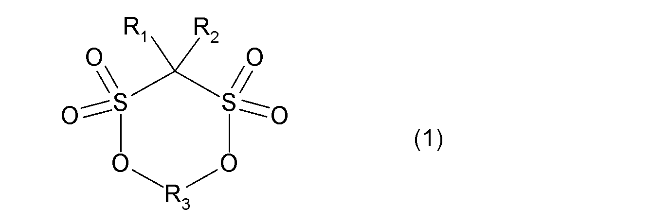
(一般式(1)中、R1、R2はそれぞれ独立に水素原子、ハロゲン原子、炭素数1~5のアルキル基、又はアミノ基を示す。但し、R1、R2の少なくとも一方は水素原子以外である。R3は炭素数1~5のアルキレン基、カルボニル基、スルフィニル基、炭素数1~6のフルオロアルキレン基、エーテル結合を介してアルキレン単位またはフルオロアルキレン単位が結合した炭素数2~6の2価の基からなる群の中から選ばれる連結基を示す。)
本発明の実施形態により、クーロン効率に優れた非水電解液二次電池が提供できる。
以下、本発明の一実施形態について説明する。
<非水電解液>
本実施形態におけるリチウム二次電池の電解液(以下、「非水電解液」または単に「電解液」と記載することもある。)は、添加剤として、一般式(1)で表される環状スルホン酸エステル(以下、単に「一般式(1)の化合物」と記載することもある。)を含有する。
本実施形態におけるリチウム二次電池の電解液(以下、「非水電解液」または単に「電解液」と記載することもある。)は、添加剤として、一般式(1)で表される環状スルホン酸エステル(以下、単に「一般式(1)の化合物」と記載することもある。)を含有する。

(一般式(1)中、R1、R2はそれぞれ独立に水素原子、ハロゲン原子、炭素数1~5のアルキル基、又はアミノ基を示す。但し、R1、R2の少なくとも一方は水素原子以外である。R3は炭素数1~5のアルキレン基、カルボニル基、スルフィニル基、炭素数1~6のフルオロアルキレン基、エーテル結合を介してアルキレン単位またはフルオロアルキレン単位が結合した炭素数2~6の2価の基からなる群の中から選ばれる連結基を示す。)
非水電解液に含まれる一般式(1)で表される環状スルホン酸エステルは、充放電反応時の電気化学的酸化還元反応により分解して負極活物質表面に皮膜を形成し、電解液や支持塩の分解を抑制することができる。これにより、リチウムイオン二次電池の長寿命化に効果があると考えられる。このような一般式(1)の化合物を含有する電解液では、保管安定性が向上し、劣化が抑制され、またこの電解液を用いた場合にリチウムイオン二次電池の容量維持、保存特性、特に、自己放電に伴う残存容量の維持特性が格段に向上する。
上記の一般式(1)で表される環状スルホン酸エステルは、R1、R2のいずれかが置換されていることによりR1、R2の両方が水素原子であるスルホン酸エステルに比べて負極表面上に形成される皮膜形成能が向上する。また、上記の一般式(1)で表される環状スルホン酸エステルは、R1、R2のいずれかが置換されていることにより、R1、R2の両方が水素原子である化合物に比べて、水分、特に負極活物質に含まれる残存水分の影響が緩和され、電解液の安定性が向上し、これを用いたリチウムイオン二次電池は、初期容量が向上する。
水分の影響が緩和される原因は、正確には確認されていないが、以下のような反応機構と予測している。電解液中には、支持電解質としてリチウム塩が添加されており、代表的にはLiPF6などのフッ素含有化合物が用いられている。特許文献1に記載されるように、当該フッ素含有化合物は水と反応してフッ化水素を発生させる(スキーム1)。スキーム1において、式(a)は、LiPF6の電離反応、式(b)はフッ化リチウムと5フッ化リンへの平衡解離反応、式(c)は5フッ化リンと水との反応を示す。
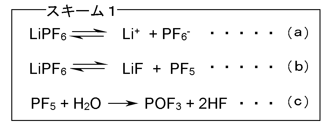
一般式(1)におけるR1、R2が置換するα位炭素は、無置換の添加剤(ここでは、R3がメチレンの化合物であり、添加剤X1とする)の場合は負極中の水の影響によりα位炭素上の水素が引き抜かれやすくなる。負極表面上に吸着する添加剤X1は、水素が引き抜かれた後、電解液中の遊離Liイオン(式(a))と結合してLi塩を形成して電解液中に溶出することで、負極活物質表面への皮膜形成能が低下することになる。これに対して、α位炭素がメチル基などの置換基で置換されている場合、α位炭素からの水素引き抜きが抑制され、皮膜形成能の低下が抑制される。
一般式(1)の化合物においては、R1およびR2の少なくとも1つがアルキル基である化合物が好ましい。特に、1つがアルキル基で他方が水素原子であるか、2つともアルキル基である化合物が好ましい。
R1およびR2のアルキル基としては、メチル、エチル、プロピル、ブチルおよびペンチルが挙げられ、これらは、直鎖でも分岐でもよい。特に、メチル、エチルおよびプロピルが好ましい。ハロゲン原子としては、フッ素原子、塩素原子、臭素原子等が挙げられるが、フッ素原子が好ましい。
R3は、炭素数1~5のアルキレン基、カルボニル基、スルフィニル基、炭素数1~6のフルオロアルキレン基、エーテル結合を介してアルキレン単位またはフルオロアルキレン単位が結合した炭素数2~6の2価の基からなる群の中から選ばれる連結基を示す。炭素数1~5のアルキレン基としては、メチレン、エチレン(1,1-エチレン、1,2-エチレン)、2,2-プロピレンが好ましく、炭素数1~6のフルオロアルキレン基としては、モノフルオロメチレン、ジフルオロメチレン、モノフルオロエチレン、ジフルオロエチレン、トリフルオロエチレンおよびテトラフルオロエチレンが好ましい。R3は、好ましくは、炭素数1~5のアルキレン基、炭素数1~6のフルオロアルキレン基及びカルボニル基であり、中でも、メチレン又はエチレンが最も好ましい。
上記の一般式(1)の化合物は、一種を単独で使用しても二種以上を併用してもよい。
一般式(1)の化合物の代表例を表1に具体的に例示するが、本発明はこれらに限定されるものはない。
上記の一般式(1)の化合物は、一種を単独で使用しても二種以上を併用してもよい。
一般式(1)の化合物の代表例を表1に具体的に例示するが、本発明はこれらに限定されるものはない。
一般式(1)の化合物は、例えば、米国特許第4950768号(特開昭61-501089号公報、特公平5-44946号公報)、特開2005-336155号公報などに記載されている製造方法を用いて得ることができる。
一般式(1)の化合物の電解液に占める割合は特に限定されないが、電解液全体の0.005~10質量%で含まれることが好ましい。一般式(1)の化合物の濃度を0.005質量%以上とすることにより、低抵抗な皮膜を得ることができる。より好ましくは0.01質量%以上添加されると電池特性をさらに向上させることができる。また、10質量%以下とすることにより、電解液の粘性の上昇、およびそれに伴う抵抗の増加を抑制することができる。より好ましくは5質量%以下添加され、こうすることにより、電池特性をさらに向上させることができる。
非水電解液としては特に限定されないが、例えばリチウム塩を非水溶媒に溶解した溶液に上記一般式(1)の化合物を加えて用いることができる。
リチウム塩としては、LiPF6、リチウムイミド塩、LiAsF6、LiAlCl4、LiClO4、LiBF4、LiSbF6等が挙げられる。リチウムイミド塩としては、LiN(CkF2k+1SO2)(CmF2m+1SO2)(kおよびmは、それぞれ独立して自然数、好ましくは1または2である)が挙げられる。これらは一種のみを用いてもよく、二種以上を併用してもよい。特にフッ素含有リチウム塩を1種以上含むことが好ましく、中でもLiPF6が最も好ましい。
非水電解液中のリチウム塩の濃度としては、0.7mol/L以上、2.0mol/L以下であることが好ましい。リチウム塩の濃度を0.7mol/L以上とすることにより、十分なイオン導電性が得られる。また、リチウム塩の濃度を2.0mol/L以下とすることにより、粘度を低くすることができ、リチウムイオンの移動が妨げられない。
非水溶媒としては、環状カーボネート、鎖状カーボネート、脂肪族カルボン酸エステル、γ-ラクトン、環状エーテルおよび鎖状エーテルからなる群から選択される少なくとも1種の溶媒を用いることができる。環状カーボネートとしては、プロピレンカーボネート(PC)、エチレンカーボネート(EC)、ブチレンカーボネート(BC)、およびこれらの誘導体(フッ素化物を含む)が挙げられる。鎖状カーボネートとしては、ジメチルカーボネート(DMC)、ジエチルカーボネート(DEC)、エチルメチルカーボネート(EMC)、ジプロピルカーボネート(DPC)、およびこれらの誘導体(フッ素化物を含む)が挙げられる。脂肪族カルボン酸エステルとしては、ギ酸メチル、酢酸メチル、プロピオン酸エチル、およびこれらの誘導体(フッ素化物を含む)が挙げられる。γ-ラクトンとしては、γ-ブチロラクトンおよびその誘導体(フッ素化物を含む)が挙げられる。環状エーテルとしては、テトラヒドロフラン、2-メチルテトラヒドロフランおよびその誘導体(フッ素化物を含む)が挙げられる。鎖状エーテルとしては、1,2-ジエトキシエタン(DEE)、エトキシメトキシエタン(EME)、エチルエーテル、ジエチルエーテル、およびこれらの誘導体(フッ素化物を含む)が挙げられる。非水溶媒としては、これら以外にも、ジメチルスルホキシド、1,3-ジオキソランや置換ジオキソランなどのジオキソラン誘導体、ホルムアミド、アセトアミド、ジメチルホルムアミド、アセトニトリル、プロピルニトリル、ニトロメタン、エチルモノグライム、リン酸トリエステル類、トリメトキシメタン、スルホラン、メチルスルホラン、1,3-ジメチル-2-イミダゾリジノン、3-メチル-2-オキサゾリジノン、1,3-プロパンスルトン、アニソール、N-メチルピロリドン、およびこれらの誘導体(フッ素化物を含む)を用いることもできる。これらは一種のみを用いてもよく、二種以上を併用してもよい。特に環状カーボネートと鎖状カーボネートとの組み合わせが好ましく使用できる。
本実施形態の電解液は、少なくとも1個のスルホニル基を有する化合物をさらに含むことができる。ここで、少なくとも1個のスルホニル基を有する化合物(以下、スルホニル基含有化合物ともいう。)は、前記一般式(1)で表される環状スルホン酸エステルとは異なる化合物である。尚、スルホニル基含有化合物としては、上記の非水溶媒と重複する化合物もあるが、「スルホニル基含有化合物」は、通常、環状カーボネート類、鎖状カーボネート類、脂肪族カルボン酸エステル類、γ-ラクトン類、環状エーテル類、鎖状エーテル類およびこれらの化合物のフッ素誘導体からなる群より選択される少なくとも1種の非水溶媒とともに使用される。
前記スルホニル基含有化合物として、下記一般式(2)又は(3)で示されるスルトン化合物が好ましい。


一般式(2)中、nは0~2の整数を表し、R4~R9は、互いに独立に、水素原子、炭素数1~12のアルキル基、炭素数3~6のシクロアルキル基または炭素数6~12のアリール基を表す。
一般式(3)中、mは0~3の整数を表し、R10~R13は、水素原子、フッ素原子または炭素数1~12のフッ素原子を含んでいても良いアルキル基、炭素数3~6のシクロアルキル基または炭素数6~12のアリール基を表す。
一般式(2)で表される化合物としては、例えば1,3-プロパンスルトン(PS)、1,4-ブタンスルトン等の飽和環状スルホン酸エステル類が挙げられ、一般式(3)で表される化合物としては、1,3-プロパ-2-エンスルトン等の不飽和環状スルホン酸エステル類が挙げられる。これらは1種を単独で、又は2種以上を組み合わせて使用することができる。一般式(2)又は(3)で表されるスルトン化合物を添加することにより、電解液の粘度の調整が容易になる。また、スルホニル基を有する化合物を組み合わせて用いることに起因する相乗効果により、負極表面の皮膜の安定性を向上させることができる。更に、溶媒分子の分解を抑制して、電解液中の水分の除去効果を大きくすることができる。
スルホニル基含有化合物は、電解液全体の0.005~10質量%の範囲で使用される。
また、本実施形態の電解液は、ビニレンカーボネートまたはその誘導体をさらに含むことができる。ビニレンカーボネートまたはその誘導体としては、ビニレンカーボネート(VC)、4-メチルビニレンカーボネート、4,5-ジメチルビニレンカーボネート、4-エチルビニレンカーボネート、4,5-ジエチルビニレンカーボネート、4-プロピルビニレンカーボネート、4,5-ジプロピルビニレンカーボネート、4-フェニルビニレンカーボネートおよび4,5-ジフェニルビニレンカーボネート等のビニレンカーボネート類;並びにビニルエチレンカーボネート(VEC)、ジビニルエチレンカーボネート等のビニルアルキレンカーボネート類を挙げることができる。
ビニレンカーボネートまたはその誘導体は、電解液全体の0.005~10質量%で使用される。
また、本実施形態において、電解液には、必要に応じて、上記化合物以外のその他の添加剤も含めることができる。その他の添加剤としては、例えば、過充電防止剤、界面活性剤、が挙げられる。
<負極>
負極は、負極集電体上に、負極活物質と結着剤(バインダ)とを含む負極活物質層を形成することで作製することができる。
負極は、負極集電体上に、負極活物質と結着剤(バインダ)とを含む負極活物質層を形成することで作製することができる。
負極活物質としては、リチウムイオンを吸蔵、放出できる下記の材料を単独でまたは二種以上を混合して、使用することができる。
コークス類、ガラス状炭素類、黒鉛材料(グラファイト類)、難黒鉛化性炭素類、易黒鉛化炭素類、熱分解炭素類、炭素繊維等の炭素質材料、
Al、Si、Pb、Sn、Zn、Cd、Sb等を主体とした活物質、またはこれらとリチウムとの合金等の金属又は半金属材料、
LiFe2O3、WO2、MoO2、SiO、SiO2、CuO、SnO、SnO2、Nb3O5、LixTi2-xO4(0≦x≦1)、PbO2、PbO5等の金属酸化物、
SnSやFeS2等の金属硫化物、
金属リチウム、リチウム合金、ポリアセン、ポリチオフェン、
Li5(Li3N)、Li7MnN4、Li3FeN2、Li2.5Co0.5N、Li3CoN等の窒化リチウム等、これらと炭素の複合体。
コークス類、ガラス状炭素類、黒鉛材料(グラファイト類)、難黒鉛化性炭素類、易黒鉛化炭素類、熱分解炭素類、炭素繊維等の炭素質材料、
Al、Si、Pb、Sn、Zn、Cd、Sb等を主体とした活物質、またはこれらとリチウムとの合金等の金属又は半金属材料、
LiFe2O3、WO2、MoO2、SiO、SiO2、CuO、SnO、SnO2、Nb3O5、LixTi2-xO4(0≦x≦1)、PbO2、PbO5等の金属酸化物、
SnSやFeS2等の金属硫化物、
金属リチウム、リチウム合金、ポリアセン、ポリチオフェン、
Li5(Li3N)、Li7MnN4、Li3FeN2、Li2.5Co0.5N、Li3CoN等の窒化リチウム等、これらと炭素の複合体。
負極活物質として炭素質材料、特に黒鉛材料を用いることで、負極活物質表面に形成させる皮膜とバインダ・電解液界面に形成される皮膜の界面の抵抗を低減して、リチウムイオンの移動をよりスムーズにすることができる。上記黒鉛材料は、表面を核材より結晶性の低い炭素で被覆しても良い。
天然黒鉛としては、鱗片状天然黒鉛、球状天然黒鉛、塊状天然黒鉛、土状天然黒鉛が挙げられ、これらのうち球状天然黒鉛が好ましい。人造黒鉛としては、塊状人造黒鉛、鱗片状人造黒鉛、MCMB(メゾフェーズ マイクロ ビーズ)等球状の人造黒鉛が挙げられ、これらのうち塊状人造黒鉛が好ましい。難黒鉛化炭素の形状としては、塊状やフレーク状や鱗片状の形状が挙げられ、これらのうち塊状が好ましい。易黒鉛化炭素の形状としては、塊状やフレーク状や鱗片状が挙げられ、これらのうち、鱗片状が好ましい。
負極活物質に含まれる炭素質材料の形状が球状または塊状であることは、SEM(走査型顕微鏡)観察により確認することができる。
負極活物質のSEM画像においては、その短軸方向(長さが最も短い方向の長さ)と長軸方向(長さが最も長い方向の長さ)の長さの比である(短軸)/(長軸)が0.2よりも大きい場合は球状または塊状の形状と判断することができる。なお、球状黒鉛の(短軸)/(長軸)は、好ましくは0.3以上、より好ましくは0.5以上であるのが良い。
球状の黒鉛は、鱗片状の黒鉛を原料として製造され、鱗片状黒鉛が折り畳まれて球形化した構造を有している。このため、球状の黒鉛には片理が観察され、片理が種々の方向に向かうキャベツ状の外観を有している。また、球状の黒鉛の破断面には、空隙が観察される。負極活物質として球状の黒鉛を含むことにより、電極作製時の圧延工程後も結晶の配向がいろいろな方向を向くため、電極間のリチウムイオンの移動がスムーズに行われやすくなる。さらに、球状黒鉛を用いることにより、負極活物質間に電解液の保持に適した空隙を得ることができるので、高出力特性に優れたリチウムイオン非水電解液二次電池を得ることができる。
塊状の黒鉛においては、上記球状の黒鉛で観察されるような片理は観察されず、均質な形状を有している。
天然黒鉛の平均粒子径D50mは、特に限定されないが、例えば、5~80μmであることが好ましく、塊状の人造黒鉛および塊状の難黒鉛化炭素の平均粒子径D50vは、例えば、5~40μmであることが好ましい。
負極活物質として炭素質材料を一種のみ用いる場合より、二種以上の炭素質材料を混合して用いると、電解液の負極活物質層への浸み込み性、さらには補液性が向上するため好ましい。リチウムを吸蔵、放出できる材料としては、炭素質材料以外にシリコン系酸化物などを組み合わせて用いることができる。負極活物質としての炭素質材料のうち、黒鉛材料は、電子伝導性が高く、銅などの金属からなる集電体との接着性と電圧平坦性が優れており、高い処理温度によって形成されるため含有不純物が少なく、負極性能の向上に有利であり、好ましい。負極活物質としては、黒鉛を20質量%以上含むことがより好ましく、黒鉛を60質量%以上含むことがさらに好ましい。
負極集電体としては、電気化学的な安定性から、アルミニウム、ニッケル、銅、銀、およびそれらの合金が好ましい。その形状としては、箔、平板状、メッシュ状が挙げられる。
負極活物質層の形成方法としては、負極活物質を結着剤と共に適当な溶媒に分散させてペーストまたはスラリー状の負極活物質層形成用組成物(負極合剤)を得た後、かかる負極合剤を負極集電体の表面に塗付することにより形成することができる。予め負極活物質層を形成した後に、蒸着、スパッタ等の方法でアルミニウム、ニッケルまたはそれらの合金の薄膜を形成して、負極集電体としてもよい。
結着剤(バインダ)としては、非水系電解液や電極製造時に用いる溶媒に対して安定な材料であれば、特に制限されない。具体例としては、ポリエチレン、ポリプロピレン、ポリエチレンテレフタレート、ポリメチルメタクリレート、芳香族ポリアミド、セルロース、ニトロセルロース等の樹脂系高分子;SBR(スチレン・ブタジエンゴム)、イソプレンゴム、ブタジエンゴム、フッ素ゴム、NBR(アクリロニトリル・ブタジエンゴム)、エチレン・プロピレンゴム等のゴム状高分子;スチレン・ブタジエン・スチレンブロック共重合体又はその水素添加物;EPDM(エチレン・プロピレン・ジエン三元共重合体)、スチレン・エチレン・ブタジエン・スチレン共重合体、スチレン・イソプレン・スチレンブロック共重合体又はその水素添加物等の熱可塑性エラストマー状高分子;シンジオタクチック-1,2-ポリブタジエン、ポリ酢酸ビニル、エチレン・酢酸ビニル共重合体、プロピレン・α-オレフィン共重合体等の軟質樹脂状高分子;ポリフッ化ビニリデン(PVdF)、ポリテトラフルオロエチレン、フッ素化ポリフッ化ビニリデン、ポリテトラフルオロエチレン・エチレン共重合体等のフッ素系高分子;アルカリ金属イオン(特にリチウムイオン)のイオン伝導性を有する高分子組成物等が挙げられる。これらは、1種を単独で用いても、2種以上を任意の組み合わせ及び比率で併用してもよい。
スチレン系重合体には電解液が染み込みにくいことから、バインダを介した負極活物質と電解液との接触を防止して、負極活物質と電解液との副反応を防ぐことができる。また、電解液中に、環状スルホン酸エステルを有することで、負極活物質表面に安定な表面皮膜が形成され、高温環境下における電解液溶媒の分解を防ぐことができる。
本発明に係るスチレン単量体としては、スチレン、α-メチルスチレン、ジメチルスチレン、ビニルトルエンなどが挙げられるが、これらのなかでもスチレンが好ましい。
スチレン単量体と共重合が可能な単量体としては、
アクリロニトリル、メタクリロニトリル、フマロニトリルなどのビニル系の単量体、
メタクリル酸からなるメタクリル酸単量体、
メタクリル酸メチル、メタクリル酸エチル、メタクリル酸プロピル、メタクリル酸ブチル、メタクリル酸-2-エチルヘキシル、メタクリル酸フェニル、メタクリル酸ベンジル、メタクリル酸イソボルニルなどのメタクリル酸エステル系の単量体、
ブタジエン、イソプレン、クロロプレンなどのブタジエン系の単量体、
アクリル酸からなるアクリル酸単量体、
アクリル酸メチル、アクリル酸エチル、アクリル酸プロピル、アクリル酸ブチル、アクリル酸-2-エチルヘキシル、アクリル酸シクロヘキシルなどのアクリル酸エステル系の単量体、
マレイン酸、イタコン酸、シトラコン酸の無水物などの不飽和ジカルボン酸無水物系の単量体、
マレイミド、N-メチルマレイミド、N-ブチルマレイミド、N-フェニルマレイミド、N-シクロヘキシルマレイミドなどの不飽和ジカルボン酸のイミド化合物系の単量体
などが挙げられる。これらの単量体は、単独または2種以上を組み合わせても使用できる。
アクリロニトリル、メタクリロニトリル、フマロニトリルなどのビニル系の単量体、
メタクリル酸からなるメタクリル酸単量体、
メタクリル酸メチル、メタクリル酸エチル、メタクリル酸プロピル、メタクリル酸ブチル、メタクリル酸-2-エチルヘキシル、メタクリル酸フェニル、メタクリル酸ベンジル、メタクリル酸イソボルニルなどのメタクリル酸エステル系の単量体、
ブタジエン、イソプレン、クロロプレンなどのブタジエン系の単量体、
アクリル酸からなるアクリル酸単量体、
アクリル酸メチル、アクリル酸エチル、アクリル酸プロピル、アクリル酸ブチル、アクリル酸-2-エチルヘキシル、アクリル酸シクロヘキシルなどのアクリル酸エステル系の単量体、
マレイン酸、イタコン酸、シトラコン酸の無水物などの不飽和ジカルボン酸無水物系の単量体、
マレイミド、N-メチルマレイミド、N-ブチルマレイミド、N-フェニルマレイミド、N-シクロヘキシルマレイミドなどの不飽和ジカルボン酸のイミド化合物系の単量体
などが挙げられる。これらの単量体は、単独または2種以上を組み合わせても使用できる。
スチレン系重合体としては少なくとも、スチレン単量体とブタジエン単量体を含む共重合体、又は、スチレン単量体とアクリル酸単量体を含む共重合体が好ましい。また、これらの単量体以外の単量体を更に含んだ共重合体としても良い。上記のバインダを用いることで、負極中のバインダ・電解液界面に、より電気伝導性の高い皮膜が形成され、長期的にリチウムイオンをよりスムーズに移動させることができる。
スチレン単量体とブタジエン単量体を含む共重合体としては、スチレン・ブタジエン共重合体(SBR)、スチレン・エチレン・ブタジエン共重合体、メタクリル酸メチル・スチレン・ブタジエン共重合体、メチルメタクリレート・スチレン・ブタジエン共重合体、アクリロニトリル・スチレン・ブタジエン共重合体など、スチレン・ブタジエン共重合体の一部に他のモノマーを添加させたものを用いても良い。スチレン単量体とアクリル酸単量体を含む共重合体としては、スチレン・アクリル共重合体、アクリル・スチレン・アクリロニトリル共重合体を用いても良い。
上記のスチレン系重合体をバインダとして用いることで、高温環境下における電解液中へのバインダ溶出をより確実に抑制できることから、電極の密着性をより確実に維持できる。
上記のスチレン系重合体において、スチレン系重合体中のスチレン単量体の含量の範囲は、5~80質量%が好ましく、より好ましくは15~70質量%、更に好ましくは25~60質量%が良い。これらの範囲とすることで、電極の密着性を維持しつつ、バインダ・電解液界面に形成される皮膜の抵抗をより低くすることができる。
使用する結着剤の量は、トレードオフの関係にある十分な結着力と高エネルギー化の観点から、負極活物質層中に、0.3~16質量%、好ましくは0.3~8.0質量%の範囲で含まれるのが良い。スチレン系重合体を使用する場合、より好ましくは0.5~6.0質量%、更に好ましくは0.8~5.0質量%、特に1.0~3.5質量%の範囲で含まれるのが良い。
ペースト又はスラリーを調製するための溶媒としては、負極活物質、結着剤、必要に応じて使用される増粘剤及び導電材を溶解又は分散することが可能な溶媒であれば、その種類に特に制限はなく、水系溶媒と有機系溶媒のどちらを用いてもよい。
水系溶媒の例としては水、水と相溶性のあるアルコール等の混合溶媒が挙げられ、有機系溶媒の例としてはN-メチルピロリドン(NMP)、ジメチルホルムアミド、ジメチルアセトアミド等のアミド系溶媒、アセトン、メチルエチルケトン、シクロヘキサノン等のケトン系溶媒、酢酸メチル、アクリル酸メチル等のエステル類、ジエチルトリアミン、N,N-ジメチルアミノプロピルアミン等の有機アミン類、テトラヒドロフラン(THF)、トルエン、ジエチルエーテル、ヘキサメチルホスファルアミド、ジメチルスルホキシド(DMSO)、ベンゼン、キシレン、キノリン、ピリジン、メチルナフタレン、ヘキサン等が挙げられる。
例えば、結着剤としてPVdF等のフッ素系高分子を使用する場合には、NMP等の有機系溶媒との組み合わせが好ましく、SBR等のスチレン系重合体の場合は水系溶媒との組み合わせが好ましい。
NMP等の有機系溶剤の一部は吸湿性が高く、製品自体もある程度の水分を含んでいるが、合剤調製段間での環境によっても合剤中の水分量が変わり得ることが知られている。水分量の上昇はゲル化を促し、合剤(ペースト)の粘度が上昇して取り扱い性が悪化する。したがって、合剤の調製は露点温度10℃(25℃、相対湿度40%)以下の低湿環境下で行うことが好ましい。
水系溶媒中に負極活物質及び結着剤を分散性よく分散させるため、また、スラリーの粘度を調整するため、水系増粘剤や分散剤を添加することが好ましい。このような水系増粘剤としては、カルボキシメチルセルロース(CMC)、メチルセルロース(MC)、酢酸フタル酸セルロース(CAP)、ヒドロキシプロピルメチルセルロース(HPMC)、ヒドロキシプロピルメチルセルロースフタレート(HPMCP)等のセルロース系ポリマー;ポリビニルアルコール(PVA)等が例示される。水系溶媒を用いる合剤の調製段階では、露点管理等は不要である。
このような負極合剤は、塗布した後乾燥して負極活物質層を形成するが、高温での乾燥では得られる負極の表面にき裂を生じ、クーロン効率などの電池特性が著しく低下するなどの弊害がある。そのため、50ppm未満まで乾燥することは避けるべきである。一方、1000ppmを超える水分量は、一般式(1)の化合物による低抵抗な皮膜と共に副反応による高抵抗な皮膜が形成されやすくなり、電池特性が低下する。従って、本発明では、負極活物質層中の水分量を50~1000ppmの範囲で制御する。尚、負極活物質層中の水分量は、一般的なカールフィッシャー法で測定することにより確認することができる。また、「ppm」は質量基準である。
水分量は、ペースト又はスラリー状の負極合剤中の水分量、負極合剤中の成分に応じて乾燥温度、乾燥時間、乾燥雰囲気の条件(湿度(露点温度)や圧力)等の乾燥条件を調節することで、上記範囲内となるように調整される。また、乾燥前又は乾燥後、所望により厚み方向にプレスして所望の膜厚の負極とすることができる。
また、実際の電池製造工程では、負極製造から電池組み立てまでの間に長い時間を要することがある。黒鉛などの炭素質材料やCMC等の水系増粘剤は吸湿しやすいため、乾燥直後に上記の範囲内となったとしても、保存時の管理が不十分であると徐々に水分量が増加する。したがって、乾燥後の負極は、露点温度の管理された環境下にて保存されることが好ましい。例えば、露点温度を0℃以下、好ましくは-5℃以下に管理された環境下にて保存する。また、本発明では水分量の上限値が比較的高いために、過度に低い露点温度、例えば-30℃以下とする必要はない。典型的には露点温度-10℃の環境下に保持される。
負極合剤には、上記以外に、導電剤、補強材、レベリング剤、電解液分解抑制等の機能を有する電解液添加剤等の、他の成分が含まれていてもよい。
<正極>
正極活物質としては、例えば、LiCoO2、LiNiO2、Li(Ni,Mn,Co)O2、LiMn2O4などのリチウム含有複合酸化物があげられる。また、これらのリチウム含有複合酸化物の遷移金属部分を他元素で置き換えたものでもよい。また、金属リチウム対極電位で4.2V以上にプラトーを有するリチウム含有複合酸化物を用いることもできる。リチウム含有複合酸化物としては、スピネル型リチウムマンガン複合酸化物、オリビン型リチウム含有複合酸化物、逆スピネル型リチウム含有複合酸化物等が例示される。リチウム含有複合酸化物は、例えば下記の式(4)で表される化合物を挙げることができる。
正極活物質としては、例えば、LiCoO2、LiNiO2、Li(Ni,Mn,Co)O2、LiMn2O4などのリチウム含有複合酸化物があげられる。また、これらのリチウム含有複合酸化物の遷移金属部分を他元素で置き換えたものでもよい。また、金属リチウム対極電位で4.2V以上にプラトーを有するリチウム含有複合酸化物を用いることもできる。リチウム含有複合酸化物としては、スピネル型リチウムマンガン複合酸化物、オリビン型リチウム含有複合酸化物、逆スピネル型リチウム含有複合酸化物等が例示される。リチウム含有複合酸化物は、例えば下記の式(4)で表される化合物を挙げることができる。
Lia(MxMn2-x)O4 (4)
(ただし、式(4)において、0<x<2であり、また、0<a<1.2である。また、Mは、Ni、Co、Fe、CrおよびCuよりなる群から選ばれる少なくとも一種である。)
(ただし、式(4)において、0<x<2であり、また、0<a<1.2である。また、Mは、Ni、Co、Fe、CrおよびCuよりなる群から選ばれる少なくとも一種である。)
正極用結着剤としては、負極用結着剤と同様のものを用いることができる。中でも、汎用性や低コストの観点から、ポリフッ化ビニリデンが好ましい。使用する正極用結着剤の量は、トレードオフの関係にある結着力とエネルギー密度の観点から、正極活物質100質量部に対して2~10質量部が好ましい。
ポリフッ化ビニリデン(PVdF)以外の結着剤としては、ビニリデンフルオライド-ヘキサフルオロプロピレン共重合体、ビニリデンフルオライド-テトラフルオロエチレン共重合体、スチレン-ブタジエン共重合ゴム、ポリテトラフルオロエチレン、ポリプロピレン、ポリエチレン、ポリイミド、ポリアミドイミドが挙げられる。
正極用集電体としては、アルミニウム、ニッケル、銀、およびそれらの合金が好ましい。その形状としては、箔、平板状、メッシュ状が挙げられる。
正極は、例えば活物質を、カーボンブラック等の導電性物質、ポリフッ化ビニリデン(PVdF)等の結着剤とともにN-メチル-2-ピロリドン(NMP)等の溶剤中に分散混練し、これをアルミニウム箔等の正極集電体上に塗布することにより得ることができる。
<二次電池の構造および製造方法>
本発明の非水電解液を用いた二次電池の構成について図面を参照しながら説明する。図1は、本発明の非水電解液を用いた二次電池の概略構成図の一例である。本発明に係る電池は、たとえば図1のような構造を有する。正極は、正極活物質を含有する層1が正極集電体3上に成膜して成る。負極は、負極活物質を含有する層2が負極集電体4上に成膜して成る。この例では、正極及び負極は、それぞれ集電体の両面に活物質層を形成する場合を示しているが、これに限定されず、片側のみに形成したものでもよい。これらの正極と負極は、多孔質セパレータ5を介して対向配置されている。多孔質セパレータ5は、負極活物質を含有する層2に対して略平行に配置されている。本発明の二次電池は、これら正極および負極が対向配置された電極素子と、電解液6とが外装体9に内包されている。正極集電体3には正極タブ7が接続けられ、負極集電体4には負極タブ8が接続され、これらのタブは外装体9の外に引き出されている。
本発明の非水電解液を用いた二次電池の構成について図面を参照しながら説明する。図1は、本発明の非水電解液を用いた二次電池の概略構成図の一例である。本発明に係る電池は、たとえば図1のような構造を有する。正極は、正極活物質を含有する層1が正極集電体3上に成膜して成る。負極は、負極活物質を含有する層2が負極集電体4上に成膜して成る。この例では、正極及び負極は、それぞれ集電体の両面に活物質層を形成する場合を示しているが、これに限定されず、片側のみに形成したものでもよい。これらの正極と負極は、多孔質セパレータ5を介して対向配置されている。多孔質セパレータ5は、負極活物質を含有する層2に対して略平行に配置されている。本発明の二次電池は、これら正極および負極が対向配置された電極素子と、電解液6とが外装体9に内包されている。正極集電体3には正極タブ7が接続けられ、負極集電体4には負極タブ8が接続され、これらのタブは外装体9の外に引き出されている。
二次電池の製造方法の一例として、図1の二次電池の製造方法を説明する。乾燥空気または不活性ガス雰囲気において、負極および正極を、多孔質セパレータ5を介して積層したものを合成樹脂と金属箔との積層体からなる可とう性フィルム等の外装体9に収容し、非水電解液6を含浸させる。そして、外装体9を封止前または封止後に、非水電解液二次電池の充電を行うことにより、負極上に良好な皮膜を形成させることができる。なお、多孔質セパレータ5としては、ポリプロピレン、ポリエチレン等のポリオレフィン、フッ素樹脂等の多孔性フィルムが用いられる。外装体9としては、電解液6に安定で、かつ十分な水蒸気バリア性を持つものであれば、適宜選択することができる。例えば、積層ラミネート型の二次電池の場合、外装体としては、アルミニウム、シリカをコーティングしたポリプロピレン、ポリエチレン等のラミネートフィルムを用いることができる。特に、体積膨張を抑制する観点から、アルミニウムラミネートフィルムを用いることが好ましい。
本実施の形態に係る非水電解液二次電池の形状としては、例示したラミネート外装型に限定されず、正極および負極が対向配置された電極素子を捲回し、金属缶に封入した円筒型、角型電池や、コイン型電池などが挙げられる。
<実施例1>
(電池の作製)
本実施例の電池の作製について説明する。正極集電体として厚み20μmのアルミニウム箔を用い、正極活物質としてLi(Mn0.95Li0.01Mg0.01Al0.01Co0.01B0.01)2O4とLiNi0.5Mn0.3Co0.2O2との重量比30:70の混合物を用いた。かつ、正極用結着剤としてPVdF(株式会社クレハ製KFポリマー)を用い、導電付与材としてアセチレンブラック(ティムカル・グラファイト・アンド・カーボン社製)を用いた。また、負極集電体として厚み10μmの銅箔を用い、この銅箔上に負極活物質として黒鉛を、負極用結着剤としてPVdF(株式会社クレハ製KFポリマー)を用い、導電付与材としてアセチレンブラック(ティムカル・グラファイト・アンド・カーボン社製)を用いた。
(電池の作製)
本実施例の電池の作製について説明する。正極集電体として厚み20μmのアルミニウム箔を用い、正極活物質としてLi(Mn0.95Li0.01Mg0.01Al0.01Co0.01B0.01)2O4とLiNi0.5Mn0.3Co0.2O2との重量比30:70の混合物を用いた。かつ、正極用結着剤としてPVdF(株式会社クレハ製KFポリマー)を用い、導電付与材としてアセチレンブラック(ティムカル・グラファイト・アンド・カーボン社製)を用いた。また、負極集電体として厚み10μmの銅箔を用い、この銅箔上に負極活物質として黒鉛を、負極用結着剤としてPVdF(株式会社クレハ製KFポリマー)を用い、導電付与材としてアセチレンブラック(ティムカル・グラファイト・アンド・カーボン社製)を用いた。
負極の形成は、黒鉛(平均粒子径:10μm)の45質量部、PVdFの2.5質量部、アセチレンブラックの2.5質量部をNMP(含水量:800ppm)50質量部に分散して負極ペーストを調製し、これを負極集電体上にアプリケーターを用いて70μm厚に塗布した。その後、負極を露点マイナス10℃の環境で、200℃での減圧乾燥処理を行った。この時の負極水分量は、カールフィッシャー法(300℃)による測定により68ppmであることが確認された。そして、負極と正極とをポリエチレンからなるセパレータを介して積層し、電極素子を作製した。
非水電解液の溶媒としてPC、EC、DMC、EMC、DECの混合溶媒(体積比:PC/EC/DMC/EMC/DEC=5/35/20/20/20)を用い、支持電解質としてLiPF6を非水電解液中1Mとなるように溶解した。また、添加剤として、表1に記載の化合物No.4を非水電解液中に0.1mol/L含まれるように加えた。
ラミネート外装体に、上記の電極素子の正極及び負極集電体にリード端子をそれぞれ取り付けて封入し、上記の非水電解液を注入して真空封止を行い、非水電解液二次電池を作製した。この非水二次電池を用いて、電池の充放電試験を行い、クーロン効率を測定した。結果を表3に示す。
この時の充放電条件は、CCCV充電レート1.0C、CC放電レート1.0C、充電終止電圧4.2V、放電終止電圧3.0Vとした。なお、1.0Cとは、満充電状態から1時間で放電しきる電流値である。
<実施例2>
負極集電体として厚み10μmの銅箔を用いた。スラリー増粘剤としてカルボキシメチルセルロース(以下、「CMC」と呼ぶ)を含む水溶液中に黒鉛を投入・攪拌し、均一なスラリーとなった段階で、バインダとしてのスチレン・ブタジエン共重合体(スチレン系重合体)を投入した。この後、更に攪拌し、単位面積当たりの容量が等しくなるように均一に塗布して、実施例1と同様に乾燥させた。この後、ロールプレスで圧縮成型することにより、負極活物質層全体に対して、CMCを2質量%、スチレン系重合体を2質量%含む負極電極を作製した。用いた負極以外は、実施例1と同様に二次電池を作製し、実施例1と同様にクーロン効率を調べた。
負極集電体として厚み10μmの銅箔を用いた。スラリー増粘剤としてカルボキシメチルセルロース(以下、「CMC」と呼ぶ)を含む水溶液中に黒鉛を投入・攪拌し、均一なスラリーとなった段階で、バインダとしてのスチレン・ブタジエン共重合体(スチレン系重合体)を投入した。この後、更に攪拌し、単位面積当たりの容量が等しくなるように均一に塗布して、実施例1と同様に乾燥させた。この後、ロールプレスで圧縮成型することにより、負極活物質層全体に対して、CMCを2質量%、スチレン系重合体を2質量%含む負極電極を作製した。用いた負極以外は、実施例1と同様に二次電池を作製し、実施例1と同様にクーロン効率を調べた。
<実施例3>
負極の減圧乾燥処理温度を180℃とした以外は、実施例2と同様に二次電池を作製し、実施例1と同様にクーロン効率を調べた。結果を表3に示す。
負極の減圧乾燥処理温度を180℃とした以外は、実施例2と同様に二次電池を作製し、実施例1と同様にクーロン効率を調べた。結果を表3に示す。
<実施例4>
負極の減圧乾燥処理温度を130℃とした以外は、実施例2と同様に二次電池を作製し、実施例1と同様にクーロン効率を調べた。結果を表3に示す。
負極の減圧乾燥処理温度を130℃とした以外は、実施例2と同様に二次電池を作製し、実施例1と同様にクーロン効率を調べた。結果を表3に示す。
<実施例5>
負極の減圧乾燥処理温度を80℃とし、かつ、減圧乾燥処理後に露点マイナス10℃の環境で、1週間(168h)放置した。その後、実施例2と同様に二次電池を作製し、実施例1と同様にクーロン効率を調べた。結果を表3に示す。
負極の減圧乾燥処理温度を80℃とし、かつ、減圧乾燥処理後に露点マイナス10℃の環境で、1週間(168h)放置した。その後、実施例2と同様に二次電池を作製し、実施例1と同様にクーロン効率を調べた。結果を表3に示す。
<比較例1>
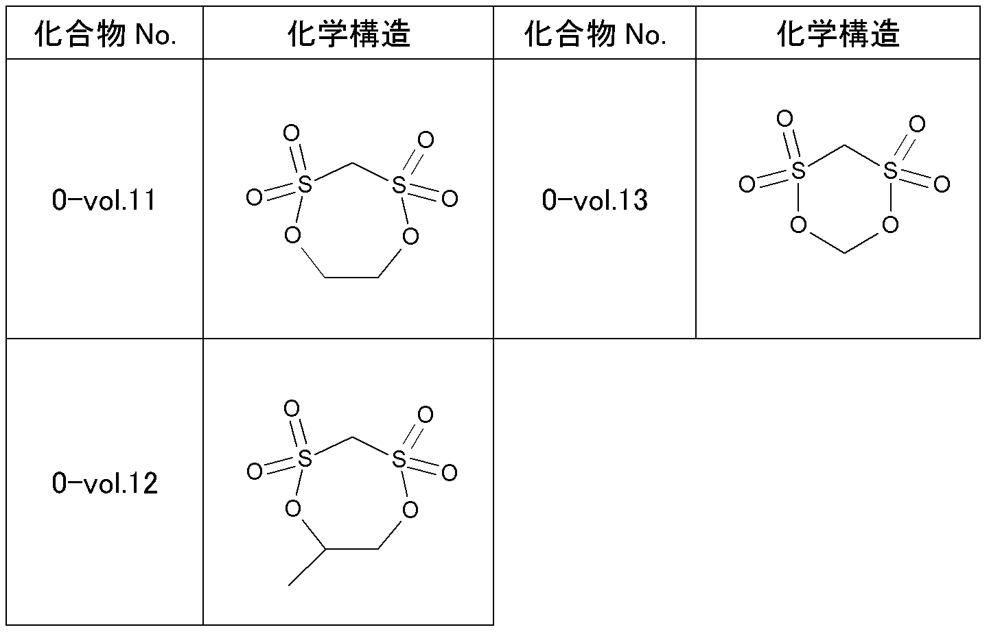
添加剤として、化合物No.4の代わりに表2記載の化合物0-vol.11を用いたこと以外は、実施例2と同様に二次電池を作製し、実施例1と同様にクーロン効率を調べた。結果を表3に示す。
添加剤として、化合物No.4の代わりに表2記載の化合物0-vol.11を用いたこと以外は、実施例2と同様に二次電池を作製し、実施例1と同様にクーロン効率を調べた。結果を表3に示す。
<比較例2>
添加剤として、化合物No.4の代わりに表2記載の化合物0-vol.12を用いたこと以外は、実施例3と同様に二次電池を作製し、実施例1と同様にクーロン効率を調べた。結果を表3に示す。
添加剤として、化合物No.4の代わりに表2記載の化合物0-vol.12を用いたこと以外は、実施例3と同様に二次電池を作製し、実施例1と同様にクーロン効率を調べた。結果を表3に示す。
<比較例3>
添加剤として、化合物No.4の代わりに表2記載の化合物0-vol.13を用いたこと以外は、実施例3と同様に二次電池を作製し、実施例1と同様にクーロン効率を調べた。結果を表3に示す。
添加剤として、化合物No.4の代わりに表2記載の化合物0-vol.13を用いたこと以外は、実施例3と同様に二次電池を作製し、実施例1と同様にクーロン効率を調べた。結果を表3に示す。
<比較例4>
添加剤として、化合物No.4の代わりに表2記載の化合物0-vol.11を用いたこと以外は、実施例5と同様に二次電池を作製し、実施例1と同様にクーロン効率を調べた。結果を表3に示す。
添加剤として、化合物No.4の代わりに表2記載の化合物0-vol.11を用いたこと以外は、実施例5と同様に二次電池を作製し、実施例1と同様にクーロン効率を調べた。結果を表3に示す。
<比較例5>
負極の減圧乾燥処理温度を250℃とした以外は、実施例2と同様に二次電池を作製し、実施例1と同様にクーロン効率を調べた。結果を表3に示す。
負極の減圧乾燥処理温度を250℃とした以外は、実施例2と同様に二次電池を作製し、実施例1と同様にクーロン効率を調べた。結果を表3に示す。
<比較例6>
添加剤として、化合物No.4の代わりに表2記載の化合物0-vol.11を用いたこと以外は、比較例5と同様に二次電池を作製し、実施例1と同様にクーロン効率を調べた。結果を表3に示す。
添加剤として、化合物No.4の代わりに表2記載の化合物0-vol.11を用いたこと以外は、比較例5と同様に二次電池を作製し、実施例1と同様にクーロン効率を調べた。結果を表3に示す。
<比較例7>
負極の減圧乾燥処理温度を180℃とし、その後、露点管理を行っていない一般大気下に24h放置したこと以外は、実施例2と同様に二次電池を作製し、実施例1と同様にクーロン効率を調べた。結果を表3に示す。
負極の減圧乾燥処理温度を180℃とし、その後、露点管理を行っていない一般大気下に24h放置したこと以外は、実施例2と同様に二次電池を作製し、実施例1と同様にクーロン効率を調べた。結果を表3に示す。
<比較例8>
添加剤として、化合物No.4の代わりに表2記載の化合物0-vol.11を用いたこと以外は、比較例7と同様に二次電池を作製し、実施例1と同様にクーロン効率を調べた。結果を表3に示す。
添加剤として、化合物No.4の代わりに表2記載の化合物0-vol.11を用いたこと以外は、比較例7と同様に二次電池を作製し、実施例1と同様にクーロン効率を調べた。結果を表3に示す。
<実施例6~13>
添加剤として、化合物No.4の代わりに表3に記載の化合物を用いたこと以外は、実施例3と同様に二次電池を作製し、実施例1と同様にクーロン効率を調べた。結果を表3に示す。
添加剤として、化合物No.4の代わりに表3に記載の化合物を用いたこと以外は、実施例3と同様に二次電池を作製し、実施例1と同様にクーロン効率を調べた。結果を表3に示す。
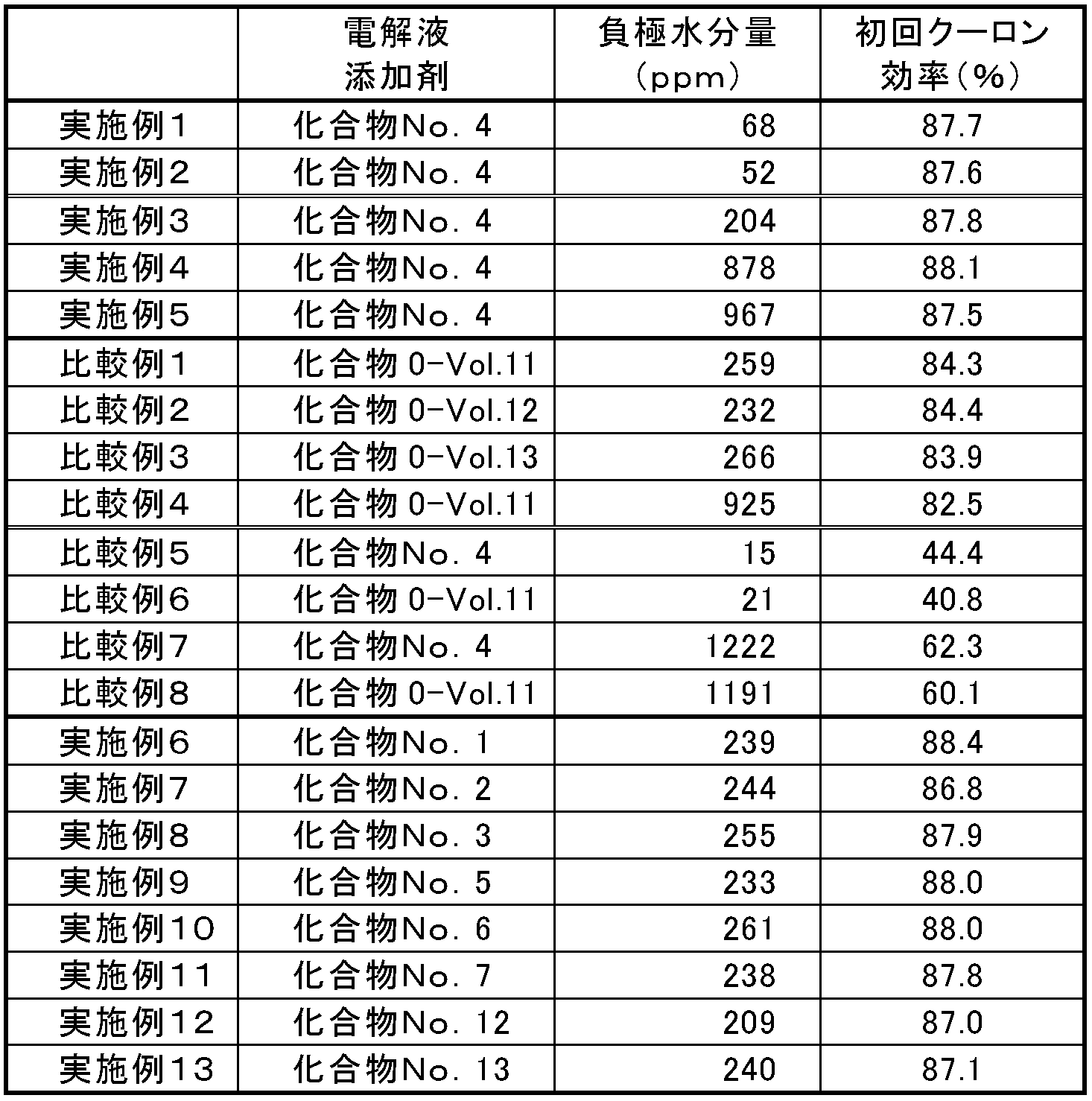
表3から明らかなように、実施例1~13に示した電池は、負極水分量が50~1000ppmの範囲であり、特定の電解液添加剤と組み合わせることによって、本発明の範囲外となる比較例1~8と比較して、クーロン効率が改善していることが確認された。
以上、実施形態及び実施例を参照して本発明を説明したが、本発明は上記実施形態及び実施例に限定されものではない。本発明の構成や詳細には、本発明のスコープ内で当業者が理解し得る様々な変更をすることができる。
本発明の活用例として、電気自動車やハイブリッド自動車、電動バイク、電動アシスト自転車などの駆動用機器、電動工具などの工具類、携帯端末やノートパソコンなどの電子機器、家庭用蓄電システムや太陽光発電システムなどの蓄電池などが挙げられる。
この出願は、2013年9月13日に出願された日本出願特願2013-190743を基礎とする優先権を主張し、その開示の全てをここに取り込む。
1 正極活物質層
2 負極活物質層
3 正極集電体
4 負極集電体
5 多孔質セパレータ
6 非水電解液
7 正極タブ
8 負極タブ
9 ラミネート外装体
2 負極活物質層
3 正極集電体
4 負極集電体
5 多孔質セパレータ
6 非水電解液
7 正極タブ
8 負極タブ
9 ラミネート外装体
Claims (18)
- 正極および負極が対向配置された電極素子と、非水電解液と、前記電極素子および前記非水電解液を内包する外装体とを有し、
前記負極における水分量が50ppm~1000ppmであって、前記非水電解液が、添加剤として一般式(1)で表される環状スルホン酸エステル誘導体を含むことを特徴とする非水電解液二次電池。

- 前記負極は、リチウムイオンを吸蔵、放出できる材料を負極活物質として含む請求項1に記載の非水電解液二次電池。
- 前記負極活物質は、天然黒鉛、人造黒鉛、難黒鉛化炭素、および易黒鉛化炭素からなる群から選ばれる一種または二種以上の炭素質材料を含むことを特徴とする請求項2に記載の非水電解液二次電池。
- 前記負極は、結着剤としてポリフッ化ビニリデンを含むことを特徴とする請求項1~3のいずれか1項に記載の非水電解液二次電池。
- 前記負極は、結着剤としてスチレン系重合体を含むことを特徴とする請求項1~3のいずれか1項に記載の非水電解液二次電池。
- 前記負極は、さらに水系増粘剤を含むことを特徴とする請求項5に記載の非水電解液二次電池。
- 前記電解液は、フッ素含有化合物を支持電解質として含む請求項1~6のいずれか1項に記載の非水電解液二次電池。
- 前記フッ素含有化合物は、LiPF6である請求項7に記載の非水電解液二次電池。
- 前記一般式(1)におけるR1とR2は、1つが炭素数1~5のアルキル基で他方が水素原子であるか、2つとも炭素数1~5のアルキル基であるであることを特徴とする請求項1~8のいずれか1項に記載の非水電解液二次電池。
- 前記一般式(1)におけるR3が炭素数1~5のアルキレン基、炭素数1~6のフルオロアルキレン基又はカルボニル基である請求項9に記載の非水電解液二次電池。
- 前記一般式(1)で表される環状スルホン酸エステルが、電解液全体の0.005質量%以上10質量%以下含まれることを特徴とする請求項1~10のいずれか1項に記載の非水電解液二次電池。
- 前記非水電解液は、カーボネート系溶媒を含む請求項1~11のいずれか1項に記載の非水電解液二次電池。
- 前記カーボネート系溶媒は、環状カーボネートと鎖状カーボネートとの混合溶媒である請求項12に記載の非水電解液二次電池。
- 前記負極は、少なくともリチウムを吸蔵、放出できる材料からなる負極活物質と結着剤とを溶媒に溶解ないしは分散して負極合剤を調製し、該負極合剤を負極集電体上に塗布した後、乾燥して前記水分量に調整されたものである請求項1~13に記載の非水電解液二次電池。
- 前記負極合剤は、黒鉛からなる負極活物質と、ポリフッ化ビニリデンからなる結着剤と、導電剤と、N-メチルピロリドンからなる溶媒から調製される請求項14に記載の非水電解液二次電池。
- 前記負極合剤は、黒鉛からなる負極活物質と、スチレン・ブタジエン共重合体からなる結着剤と、カルボキシメチルセルロースからなる増粘剤と、導電剤と、水を含む溶媒から調製される請求項14に記載の非水電解液二次電池。
- 前記負極は、前記乾燥の後、露点温度0℃以下の条件下に保持された後、電極素子として前記外装体に組み込まれたものである請求項14~16のいずれか1項に記載の非水電解液二次電池。
- 前記露点温度が-10℃である請求項17に記載の非水電解液二次電池。
Applications Claiming Priority (2)
| Application Number | Priority Date | Filing Date | Title |
|---|---|---|---|
| JP2013-190743 | 2013-09-13 | ||
| JP2013190743 | 2013-09-13 |
Publications (1)
| Publication Number | Publication Date |
|---|---|
| WO2015037367A1 true WO2015037367A1 (ja) | 2015-03-19 |
Family
ID=52665486
Family Applications (1)
| Application Number | Title | Priority Date | Filing Date |
|---|---|---|---|
| PCT/JP2014/070698 Ceased WO2015037367A1 (ja) | 2013-09-13 | 2014-08-06 | 非水電解液二次電池 |
Country Status (1)
| Country | Link |
|---|---|
| WO (1) | WO2015037367A1 (ja) |
Cited By (7)
| Publication number | Priority date | Publication date | Assignee | Title |
|---|---|---|---|---|
| WO2016174862A1 (ja) * | 2015-04-28 | 2016-11-03 | 株式会社Gsユアサ | 非水電解質蓄電素子用負極 |
| JP2017147188A (ja) * | 2016-02-19 | 2017-08-24 | エリーパワー株式会社 | 電池電極スラリーの作製方法 |
| WO2018146866A1 (ja) * | 2017-02-08 | 2018-08-16 | 株式会社村田製作所 | 二次電池用電解液、二次電池、電池パック、電動車両、電力貯蔵システム、電動工具および電子機器 |
| CN109728340A (zh) * | 2017-10-30 | 2019-05-07 | 宁德时代新能源科技股份有限公司 | 锂离子电池 |
| JP2020087569A (ja) * | 2018-11-19 | 2020-06-04 | トヨタ自動車株式会社 | 非水電解質二次電池の製造方法 |
| CN112701353A (zh) * | 2021-01-04 | 2021-04-23 | 昆山宝创新能源科技有限公司 | 电解液及其应用 |
| EP3940819A1 (en) * | 2020-07-15 | 2022-01-19 | SK Innovation Co., Ltd. | Electrode for secondary battery |
Citations (8)
| Publication number | Priority date | Publication date | Assignee | Title |
|---|---|---|---|---|
| JP2007027084A (ja) * | 2005-06-17 | 2007-02-01 | Matsushita Electric Ind Co Ltd | 非水電解液二次電池 |
| JP2007273445A (ja) * | 2006-03-09 | 2007-10-18 | Nec Tokin Corp | ポリマーゲル電解質およびそれを用いたポリマー二次電池 |
| JP2008153118A (ja) * | 2006-12-19 | 2008-07-03 | Nec Tokin Corp | 非水電解液およびそれを用いた非水電解液二次電池 |
| JP2009129747A (ja) * | 2007-11-26 | 2009-06-11 | Nec Corp | 二次電池 |
| JP2009266761A (ja) * | 2008-04-30 | 2009-11-12 | Panasonic Corp | 非水電解質二次電池及びその製造方法 |
| JP2011023221A (ja) * | 2009-07-16 | 2011-02-03 | Nec Energy Devices Ltd | リチウムイオン二次電池 |
| WO2011115247A1 (ja) * | 2010-03-18 | 2011-09-22 | Necエナジーデバイス株式会社 | リチウムイオン二次電池 |
| JP2013051200A (ja) * | 2011-07-29 | 2013-03-14 | Mitsubishi Chemicals Corp | 非水系電解液及びそれを用いた非水系電解液二次電池 |
-
2014
- 2014-08-06 WO PCT/JP2014/070698 patent/WO2015037367A1/ja not_active Ceased
Patent Citations (8)
| Publication number | Priority date | Publication date | Assignee | Title |
|---|---|---|---|---|
| JP2007027084A (ja) * | 2005-06-17 | 2007-02-01 | Matsushita Electric Ind Co Ltd | 非水電解液二次電池 |
| JP2007273445A (ja) * | 2006-03-09 | 2007-10-18 | Nec Tokin Corp | ポリマーゲル電解質およびそれを用いたポリマー二次電池 |
| JP2008153118A (ja) * | 2006-12-19 | 2008-07-03 | Nec Tokin Corp | 非水電解液およびそれを用いた非水電解液二次電池 |
| JP2009129747A (ja) * | 2007-11-26 | 2009-06-11 | Nec Corp | 二次電池 |
| JP2009266761A (ja) * | 2008-04-30 | 2009-11-12 | Panasonic Corp | 非水電解質二次電池及びその製造方法 |
| JP2011023221A (ja) * | 2009-07-16 | 2011-02-03 | Nec Energy Devices Ltd | リチウムイオン二次電池 |
| WO2011115247A1 (ja) * | 2010-03-18 | 2011-09-22 | Necエナジーデバイス株式会社 | リチウムイオン二次電池 |
| JP2013051200A (ja) * | 2011-07-29 | 2013-03-14 | Mitsubishi Chemicals Corp | 非水系電解液及びそれを用いた非水系電解液二次電池 |
Cited By (12)
| Publication number | Priority date | Publication date | Assignee | Title |
|---|---|---|---|---|
| WO2016174862A1 (ja) * | 2015-04-28 | 2016-11-03 | 株式会社Gsユアサ | 非水電解質蓄電素子用負極 |
| JPWO2016174862A1 (ja) * | 2015-04-28 | 2018-03-29 | 株式会社Gsユアサ | 非水電解質蓄電素子用負極 |
| JP2017147188A (ja) * | 2016-02-19 | 2017-08-24 | エリーパワー株式会社 | 電池電極スラリーの作製方法 |
| WO2018146866A1 (ja) * | 2017-02-08 | 2018-08-16 | 株式会社村田製作所 | 二次電池用電解液、二次電池、電池パック、電動車両、電力貯蔵システム、電動工具および電子機器 |
| JP2018129169A (ja) * | 2017-02-08 | 2018-08-16 | ソニー株式会社 | 二次電池用電解液、二次電池、電池パック、電動車両、電力貯蔵システム、電動工具および電子機器 |
| US11444324B2 (en) | 2017-02-08 | 2022-09-13 | Murata Manufacturing Co., Ltd. | Electrolyte for secondary battery, secondary battery, battery pack, electric vehicle, electric power storage system, electric tool and electronic device |
| CN109728340A (zh) * | 2017-10-30 | 2019-05-07 | 宁德时代新能源科技股份有限公司 | 锂离子电池 |
| JP2020087569A (ja) * | 2018-11-19 | 2020-06-04 | トヨタ自動車株式会社 | 非水電解質二次電池の製造方法 |
| EP3940819A1 (en) * | 2020-07-15 | 2022-01-19 | SK Innovation Co., Ltd. | Electrode for secondary battery |
| US11855248B2 (en) | 2020-07-15 | 2023-12-26 | Sk On Co., Ltd. | Electrode for secondary battery |
| US11929508B2 (en) | 2020-07-15 | 2024-03-12 | Sk On Co., Ltd. | Electrode for secondary battery |
| CN112701353A (zh) * | 2021-01-04 | 2021-04-23 | 昆山宝创新能源科技有限公司 | 电解液及其应用 |
Similar Documents
| Publication | Publication Date | Title |
|---|---|---|
| CN112313819B (zh) | 制造用于锂二次电池的负极的方法和制造锂二次电池的方法 | |
| JP6258641B2 (ja) | 非水電解液二次電池 | |
| JP6398985B2 (ja) | リチウムイオン二次電池 | |
| JP6128403B2 (ja) | リチウム二次電池 | |
| WO2010131401A1 (ja) | リチウムイオン二次電池用電極及びリチウムイオン二次電池 | |
| KR102460008B1 (ko) | 음극의 전리튬화 방법 및 이로부터 수득되는 음극 | |
| WO2015037367A1 (ja) | 非水電解液二次電池 | |
| KR20190091220A (ko) | 리튬 이차전지용 음극 및 상기 음극을 포함하는 리튬 이온 이차 전지 | |
| KR102918518B1 (ko) | 이차전지의 제조방법 | |
| KR20160005555A (ko) | 리튬전지 | |
| CN113795464B (zh) | 制造锂二次电池用正极活性材料的方法和由该方法制造的正极活性材料 | |
| CN109599548B (zh) | 正极材料及包含所述正极材料的电化学装置 | |
| WO2014133165A1 (ja) | リチウムイオン二次電池 | |
| KR102788476B1 (ko) | 음극 활물질, 이를 포함하는 음극 및 이차전지 | |
| JP2023524703A (ja) | 二次電池用電解液添加剤、それを含むリチウム二次電池用非水電解液およびリチウム二次電池 | |
| US9761854B2 (en) | Spirally-wound electrode assembly for rechargeable lithium battery and rechargeable lithium battery including same | |
| CN117219728A (zh) | 一种硅碳负极极片、锂离子电池及其制备方法 | |
| KR20160036577A (ko) | 리튬 2 차 전지 및 리튬 2 차 전지용 전해액 | |
| JP2010033830A (ja) | 非水電解質二次電池用負極およびそれを用いた非水電解質二次電池 | |
| JP6341195B2 (ja) | 二次電池用電解液およびそれを用いた二次電池 | |
| JPWO2019065288A1 (ja) | リチウムイオン二次電池用非水電解液およびそれを用いたリチウムイオン二次電池 | |
| KR20250144354A (ko) | 이차전지 | |
| CN105009349B (zh) | 锂二次电池 | |
| JP6319092B2 (ja) | 二次電池 | |
| KR20220109699A (ko) | 이차전지의 제조방법 |
Legal Events
| Date | Code | Title | Description |
|---|---|---|---|
| 121 | Ep: the epo has been informed by wipo that ep was designated in this application |
Ref document number: 14843572 Country of ref document: EP Kind code of ref document: A1 |
|
| NENP | Non-entry into the national phase |
Ref country code: DE |
|
| 122 | Ep: pct application non-entry in european phase |
Ref document number: 14843572 Country of ref document: EP Kind code of ref document: A1 |
|
| NENP | Non-entry into the national phase |
Ref country code: JP |