WO2015034045A1 - ダブルオスコネクタ - Google Patents
ダブルオスコネクタ Download PDFInfo
- Publication number
- WO2015034045A1 WO2015034045A1 PCT/JP2014/073484 JP2014073484W WO2015034045A1 WO 2015034045 A1 WO2015034045 A1 WO 2015034045A1 JP 2014073484 W JP2014073484 W JP 2014073484W WO 2015034045 A1 WO2015034045 A1 WO 2015034045A1
- Authority
- WO
- WIPO (PCT)
- Prior art keywords
- connector
- male
- female connector
- double
- male luer
- Prior art date
Links
Images


Classifications
-
- A—HUMAN NECESSITIES
- A61—MEDICAL OR VETERINARY SCIENCE; HYGIENE
- A61J—CONTAINERS SPECIALLY ADAPTED FOR MEDICAL OR PHARMACEUTICAL PURPOSES; DEVICES OR METHODS SPECIALLY ADAPTED FOR BRINGING PHARMACEUTICAL PRODUCTS INTO PARTICULAR PHYSICAL OR ADMINISTERING FORMS; DEVICES FOR ADMINISTERING FOOD OR MEDICINES ORALLY; BABY COMFORTERS; DEVICES FOR RECEIVING SPITTLE
- A61J15/00—Feeding-tubes for therapeutic purposes
- A61J15/0026—Parts, details or accessories for feeding-tubes
-
- A—HUMAN NECESSITIES
- A61—MEDICAL OR VETERINARY SCIENCE; HYGIENE
- A61M—DEVICES FOR INTRODUCING MEDIA INTO, OR ONTO, THE BODY; DEVICES FOR TRANSDUCING BODY MEDIA OR FOR TAKING MEDIA FROM THE BODY; DEVICES FOR PRODUCING OR ENDING SLEEP OR STUPOR
- A61M39/00—Tubes, tube connectors, tube couplings, valves, access sites or the like, specially adapted for medical use
- A61M39/10—Tube connectors; Tube couplings
- A61M2039/1027—Quick-acting type connectors
-
- A—HUMAN NECESSITIES
- A61—MEDICAL OR VETERINARY SCIENCE; HYGIENE
- A61M—DEVICES FOR INTRODUCING MEDIA INTO, OR ONTO, THE BODY; DEVICES FOR TRANSDUCING BODY MEDIA OR FOR TAKING MEDIA FROM THE BODY; DEVICES FOR PRODUCING OR ENDING SLEEP OR STUPOR
- A61M39/00—Tubes, tube connectors, tube couplings, valves, access sites or the like, specially adapted for medical use
- A61M39/10—Tube connectors; Tube couplings
- A61M2039/1033—Swivel nut connectors, e.g. threaded connectors, bayonet-connectors
-
- A—HUMAN NECESSITIES
- A61—MEDICAL OR VETERINARY SCIENCE; HYGIENE
- A61M—DEVICES FOR INTRODUCING MEDIA INTO, OR ONTO, THE BODY; DEVICES FOR TRANSDUCING BODY MEDIA OR FOR TAKING MEDIA FROM THE BODY; DEVICES FOR PRODUCING OR ENDING SLEEP OR STUPOR
- A61M39/00—Tubes, tube connectors, tube couplings, valves, access sites or the like, specially adapted for medical use
- A61M39/10—Tube connectors; Tube couplings
- A61M2039/1077—Adapters, e.g. couplings adapting a connector to one or several other connectors
-
- A—HUMAN NECESSITIES
- A61—MEDICAL OR VETERINARY SCIENCE; HYGIENE
- A61M—DEVICES FOR INTRODUCING MEDIA INTO, OR ONTO, THE BODY; DEVICES FOR TRANSDUCING BODY MEDIA OR FOR TAKING MEDIA FROM THE BODY; DEVICES FOR PRODUCING OR ENDING SLEEP OR STUPOR
- A61M39/00—Tubes, tube connectors, tube couplings, valves, access sites or the like, specially adapted for medical use
- A61M39/10—Tube connectors; Tube couplings
- A61M2039/1083—Tube connectors; Tube couplings having a plurality of female connectors, e.g. Luer connectors
-
- A—HUMAN NECESSITIES
- A61—MEDICAL OR VETERINARY SCIENCE; HYGIENE
- A61M—DEVICES FOR INTRODUCING MEDIA INTO, OR ONTO, THE BODY; DEVICES FOR TRANSDUCING BODY MEDIA OR FOR TAKING MEDIA FROM THE BODY; DEVICES FOR PRODUCING OR ENDING SLEEP OR STUPOR
- A61M39/00—Tubes, tube connectors, tube couplings, valves, access sites or the like, specially adapted for medical use
- A61M39/10—Tube connectors; Tube couplings
- A61M2039/1088—Tube connectors; Tube couplings having a plurality of male connectors, e.g. Luer connectors
Definitions
- the present invention relates to a double male connector having male lures at both ends.
- the present invention relates to a double male connector used for connecting female connectors at the ends of two tubes used in enteral nutrition therapy and the like.
- Enteral nutrition therapy is known as a method of administering nutrition and drugs to patients without oral administration.
- a nutrient or liquid food is passed through a nasal catheter inserted from the patient's nasal cavity into the stomach or duodenum, or a PEG (Percutaneous Endoscopic Gastrostomy) catheter inserted into the gastric fistula formed in the patient's abdomen.
- a liquid such as a drug (commonly referred to as “enteral nutrition”) is administered to the patient.
- a liquid substance to be administered to a patient is stored in a container.
- a nutrition set comprising a flexible tube is connected to the outlet port of the container.
- the downstream end of the nutrition set is connected to the upstream end of a nasal catheter or PEG catheter (hereinafter collectively referred to as “catheter”) inserted into the patient.
- a male connector is provided at the downstream end of the nutrition set.
- a female connector that can be connected to the male connector is provided at the upstream end of the catheter.
- male connectors and female connectors connectors of various shapes are actually used (see, for example, Patent Document 1).
- the liquid substance administered in enteral nutrition therapy is a low-viscosity liquid
- the liquid substance may flow back from the stomach to the esophagus, causing pneumonia, or the liquid water may not be sufficiently absorbed by the body.
- problems such as diarrhea. Therefore, in enteral nutrition therapy, the liquid material is often made highly viscous (ie, semi-solid) by adding a thromi agent or a thickener.
- Such a high-viscosity liquid material has low fluidity, and therefore has high resistance when passing through the tube. Therefore, when a liquid substance is administered to a patient, the liquid substance is fed under pressure.
- the connector that connects the nutrition set and the catheter includes a locking mechanism that engages with each other so that the connector can withstand the pressure applied to the liquid material.
- the male connector and the female connector used for such an application are internationally standardized as an international standard ISO80369-3 concerning nutritional medical devices.
- a male connector 901 considered as ISO 80369-3 has a female screw 916 surrounding a cylindrical male luer 910.
- FIGS. 11A and 11B a male connector 901 considered as ISO 80369-3 has a female screw 916 surrounding a cylindrical male luer 910.
- a female connector 902 considered as ISO 80369-3 has a male screw 926 on the outer peripheral surface of a cylindrical insertion portion (male luer) 920 into which a male luer 910 is inserted.
- Male connector 901 and female connector 902 are connected by inserting male luer 910 into insertion portion 920 and screwing female screw 916 and male screw 926 together.
- the male connector 901 and the female connector 902 are liquid-tight (property that the liquid does not leak out from the connecting portion between the male connector and the female connector even when pressure is applied to the liquid) and the connection strength (the connected male connector and Provides excellent connection with the female connector that does not separate even when a tensile force is applied.
- An object of the present invention is to provide a double male connector capable of connecting a female connector conforming to ISO 80369-3 and a conventional female connector.
- the double male connector of the present invention includes a first male luer at one end and a second male luer at the other end.
- the first male luer and the second male luer are in communication.
- the outer peripheral surface of the first male luer is a first tapered surface (conical surface) whose outer diameter decreases as it approaches the tip.
- the outer peripheral surface of the second male luer is a second tapered surface (conical surface) whose outer diameter decreases as it approaches the tip.
- the double male connector further includes a cylindrical portion surrounding the first male luer. A female screw is formed on the inner peripheral surface of the cylindrical portion.
- the first male luer and the female screw surrounding the first male luer can be connected to the female connector conforming to ISO 80369-3, and the second male luer can be connected to the conventional female connector. Therefore, for example, a nutrition set having a female connector conforming to ISO 80369-3 at the downstream end and a catheter having a conventional female connector at the upstream end are connected via the double male connector of the present invention. Can do.
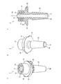
- FIG. 1A is a perspective view of a double male connector according to Embodiment 1 of the present invention as viewed from a first male luer side.
- FIG. 1B is a side view of the double male connector as viewed from the second male luer side.
- FIG. 1C is a cross-sectional view taken along a plane including the central axis of the double male connector.
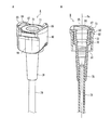
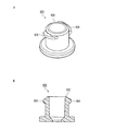
- FIG. 2A is a perspective view of the first female connector connected to the first male luer of the double male connector according to Embodiment 1 of the present invention.
- FIG. 2B is a cross-sectional view taken along a plane including the central axis of the first female connector.
- FIG. 3A is a perspective view of the second female connector connected to the second male luer of the double male connector according to Embodiment 1 of the present invention.
- FIG. 3B is a cross-sectional view along a plane including the central axis of the second female connector.
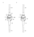
- 4A to 4C are perspective views sequentially illustrating a process of connecting the first female connector and the second female connector via the double male connector according to Embodiment 1 of the present invention.
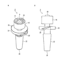
- FIG. 5A is a perspective view of a double male connector according to Embodiment 2 of the present invention as viewed from the first male luer side.
- FIG. 5B is a side view of the double male connector viewed from the second male luer side.
- FIG. 5C is a cross-sectional view along a plane including the central axis of the double male connector.
- FIG. 6A is a perspective view of a second female connector connected to a second male luer of a double male connector according to Embodiment 2 of the present invention.
- FIG. 6B is a cross-sectional view along a plane including the central axis of the second female connector.
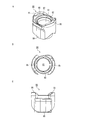
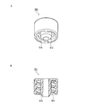
- FIG. 7A is a perspective view of a handle constituting the second female connector in Embodiment 2 of the present invention.
- FIG. 7B is a top view of the handle.
- FIG. 7C is a front view of the handle.
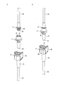
- FIG. 8A and 8B are perspective views sequentially illustrating a process of connecting the first female connector and the second female connector via the double male connector according to Embodiment 2 of the present invention.
- 9A and 9B are perspective views sequentially illustrating a process of connecting the first female connector and the second female connector via the double male connector according to Embodiment 2 of the present invention.
- FIG. 10A is a perspective view of another double male connector according to Embodiment 2 of the present invention, as viewed from the first male luer side.
- FIG. 10B is a front view of the another double male connector.
- FIG. 11A is a perspective view of a male connector being considered as ISO80369-3.
- FIG. 11B is a cross-sectional view taken along a plane including the central axis of the male connector.
- FIG. 12A is a perspective view of a female connector considered as ISO80369-3.
- FIG. 12B is a cross-sectional view along a plane including the central axis of the female
- the first tapered surface and the female screw conform to ISO 80369-3. Accordingly, the double male connector of the present invention and the female connector conforming to ISO 80369-3 can be connected in accordance with ISO 80369-3.
- the double male connector of the present invention is preferably formed integrally as a single part. Thereby, creation of a double male connector becomes easy. Moreover, the strength and durability of the double male connector are improved.
- a pair of engaging claws protruding outward is further provided between the first male luer and the second male luer. Thereby, a pair of engagement nail
- the pair of engaging claws are preferably engaged with the female connector when the second male luer is inserted into the female connector. Thereby, the connection strength between the second male luer and the female connector can be improved.
- FIG. 1A and 1B are perspective views of a double male connector 1 according to Embodiment 1 of the present invention.
- FIG. 1C is a cross-sectional view along a plane including the central axis 1 a of the double male connector 1.
- the double male connector 1 includes a cylindrical first male luer 10 at one end and a cylindrical second male luer 20 at the other end.
- the double male connector 1 is a male-male connector in which both ends are male connectors.
- the outer peripheral surface of the first male luer 10 is a tapered surface (first tapered surface) 12 whose outer diameter decreases as it approaches the tip.
- a cylindrical portion 15 is provided so as to surround the first male luer 1.
- a female screw 16 is formed on the inner peripheral surface of the cylindrical portion 15 (the surface facing the first male luer 10).
- the shape of the first taper surface 12 (outer diameter, taper angle, etc.) and the shape of the female screw 16 (diameter, pitch, etc.) are not limited, but conform to the ISO 80369-3 male connector (see FIGS. 11A and 11B) It is preferable.
- the outer peripheral surface of the second male luer 20 is also a tapered surface (second tapered surface) 22 whose outer diameter decreases as it approaches the tip.
- the shape (outer diameter, taper angle, etc.) of the second taper surface 22 is not limited, but is a conventional male luer (see, for example, FIG. 4 of Patent Document 1) suitable for a female luer (see FIGS. 3A and 3B) described later, for example. And preferably compatible.
- the flow path 9 penetrates the double male connector 1 along the central axis 1a. As a result, the first male luer 10 and the second male luer 20 communicate with each other via the flow path 9.
- the material of the double male connector 1 is not limited, but is preferably made of a hard material having such a high rigidity that it can be regarded as not substantially deformed.
- resin materials such as polyacetal, polycarbonate, polystyrene, polyamide, polypropylene, polyethylene, hard polyvinyl chloride, and ABS (acryl-butadiene-styrene copolymer) can be used.
- the double male connector 1 can be configured by combining separately created members, it is easy to manufacture the double male connector 1 that the whole is integrally formed as one part by a method such as injection molding. , Because strength and durability are improved.
- the term “integrally formed” includes a case where it is created by a two-color molding method, but a plurality of separately created parts are fitted or fused together or an adhesive is used. Does not include integration.
- FIG. 2A is a perspective view of the first female connector 6 connected to the first male luer 10 of the double male connector 1.
- FIG. 2B is a sectional view taken along a plane including the central axis 6 a of the first female connector 6.
- the first female connector 6 includes a cylindrical insertion portion 60 into which the first male luer 10 is inserted at one end.
- the inner peripheral surface of the insertion portion 60 is a tapered surface 62 whose inner diameter increases as it approaches the tip.
- a male screw 66 is formed on the outer peripheral surface of the insertion portion 60.
- the shape of the tapered surface 62 (inner diameter, taper angle, etc.) and the shape of the male screw 66 are compliant with ISO 80369-3 female connectors (see FIGS. 12A and 12B).
- the other end of the first female connector 6 is a base end portion 68 to which a flexible tube 69 is connected.
- the method for connecting the base end portion 68 and the tube 69 is not limited, but any method such as a method using an adhesive or a method using heat fusion may be used.
- the material of the first female connector 6 is not limited, but is preferably made of a hard material having such a high rigidity that it can be regarded as not substantially deformed.
- resin materials such as polyacetal, polycarbonate, polystyrene, polyamide, polypropylene, polyethylene, hard polyvinyl chloride, and ABS (acryl-butadiene-styrene copolymer) can be used.
- the first female connector 6 and the tube 69 constitute a part of a nutrition set used for enteral nutrition therapy.
- the first female connector 6 is a female connector provided at the downstream end of the nutrition set.
- a container or a syringe storing a liquid material such as a nutrient is connected to the end (upstream end) of the tube 69 opposite to the first female connector 6.
- FIG. 3A is a perspective view of the second female connector 7 connected to the second male luer 20 of the double male connector 1
- FIG. 3B is a cross-sectional view of the second female connector 7 along a plane including the central axis 7a.
- the second female connector 7 includes a cylindrical insertion portion 70 into which the second male luer 20 is inserted at one end.
- the inner peripheral surface of the insertion portion 70 is a tapered surface 72 whose inner diameter increases as it approaches the tip.
- the rib 75 improves the liquid tightness and the connection strength by being in close contact with the second tapered surface 22 of the second male luer 20 locally.
- the number of ribs 75 is arbitrary. Further, the rib 75 may be omitted.
- a flange 73 continuous in the circumferential direction protrudes outward along the radial direction.
- the flange 73 is useful for an operator to grip the insertion portion 70 when inserting the second male luer 20 into the insertion portion 70. Further, the flange 73 improves the strength of the opening end of the insertion portion 70 and prevents the opening end of the insertion portion 70 from being deformed by the inserted second male luer 20.
- the other end of the second female connector 7 is a base end portion 78 to which a flexible tube 79 is connected.
- the method for connecting the base end portion 78 and the tube 79 is not limited, but any method such as a method using an adhesive or a method using heat fusion may be used.
- the second female connector 7 is preferably made of a material softer than the second male luer 20 and is not limited, but is made of a soft material (generally called an elastomer) having flexibility (flexibility) and rubber elasticity. Is preferred.
- a soft material generally called an elastomer
- rubbers such as natural rubber, isoprene rubber, and silicone rubber, and thermoplastic elastomers such as styrene elastomer, olefin elastomer, and polyurethane elastomer can be used.
- the second female connector 7 and the tube 79 may be integrally formed using the same material.
- the second female connector 7 and the tube 79 constitute a part of a catheter such as a PEG catheter or a nasal catheter conventionally used for enteral nutrition therapy.
- the second female connector 7 is a female connector (see Patent Document 1) provided at the upstream end of the catheter.
- the opposite end (downstream end) of the tube 79 from the second female connector 7 is inserted into the patient.
- the double male connector 1 includes a first female connector 6 provided at the downstream end of the nutrition set and a second female connector 7 provided at the upstream end of the catheter. Used to connect through. Below, the usage method of the double male connector 1 is demonstrated.
- the double male connector 1 and the first female connector 6 are connected. That is, the first male luer 10 of the double male connector 1 is inserted into the insertion portion 60 of the first female connector 6. Then, the double male connector 1 is rotated with respect to the first female connector 6 so that the female screw 16 of the double male connector 1 and the male screw 66 of the first female connector 6 are screwed together. Since the shape of the first taper surface 12 (see FIG. 1C) of the first male luer 10 matches the shape of the taper surface 62 (see FIG. 2B) of the first female connector 6, the first taper surface 12 and the taper surface 62 Are in close contact. Therefore, when the male screw 66 and the female screw 16 are firmly screwed together, the double male connector 1 and the first female connector 6 are liquid-tightly connected as shown in FIG. 4B.
- the second male luer 20 of the double male connector 1 is inserted into the insertion portion 70 of the second female connector 7. Since the insertion portion 70 has rubber elasticity, as the second male luer 20 is inserted into the insertion portion 70, the insertion portion 70 is expanded in diameter by the second tapered surface 22 of the second male luer 20 and stretched in the circumferential direction. It is. As shown in FIG. 4C, when the second male luer 20 is inserted sufficiently deeply into the insertion portion 70, the insertion portion 70 becomes the second tapered surface 22 of the second male luer 20 by the elastic force of the insertion portion 70 extended in the circumferential direction. Close contact with. Thus, the double male connector 1 and the second female connector 7 are liquid-tightly connected.
- the double male connector 1 and the second female connector 7 may be connected first, and then the double male connector 1 and the first female connector 6 may be connected.
- the first female connector 6 and the second female connector 7 are connected via the double male connector 1 as shown in FIG. 4C by screwing the male screw 66 and the female screw 16 together.
- the tubes 69 and 79 may be twisted.
- the separation of the double male connector 1 from the first female connector 6 and the second female connector 7 is possible by performing the reverse operation to the above.
- the double male connector 1 includes the first male luer 10 and the female screw 16 corresponding to the first female connector 6 conforming to ISO 80369-3 at one end, and the second male connector at the other end.
- a second male luer 20 corresponding to the female connector 7 is provided. Therefore, the double male connector 1 includes a nutrition set including a female connector 6 conforming to ISO 80369-3 at the downstream end and a catheter including a conventional female connector 7 not conforming to ISO 80369-3 at the upstream end. Can be connected through.
- the double male connector 1 and the second female connector 7 are connected with the same liquid tightness and connection strength as the connection between the second female connector 7 and a conventional male connector compatible therewith.
- FIG. 5A and 5B are perspective views of the double male connector 2 according to Embodiment 2 of the present invention.
- FIG. 5C is a cross-sectional view along a plane including the central axis 2 a of the double male connector 2.
- the same elements as those of the double male connector 1 of Embodiment 1 are denoted by the same reference numerals, and description thereof will be omitted.
- the double male connector 2 according to the second embodiment will be described with a focus on differences from the first embodiment.
- the double male connector 2 of the second embodiment has a pair of engaging claws protruding outward (that is, in a direction away from the central axis 2a in the radial direction) between the first male luer 10 and the second male luer 20. 30. From the end of the cylindrical portion 15 on the second male luer 20 side, a flange 32 continuous in the circumferential direction protrudes outward along the radial direction.
- the pair of engaging claws 30 are provided on the outer peripheral surface, which is a cylindrical surface, of the flange 32. The engaging claw 30 extends along the circumferential direction (the rotational direction about the central axis 2a). As shown in FIG.
- the surface of the engaging claw 30 on the second male luer 20 side is flush with the surface of the flange 32 on the second male luer 20 side and the surface of the cylindrical portion 15 on the second male luer 20 side.
- the surface on the first male luer 10 side of the engaging claw 30 is configured by combining three inclined surfaces.
- the shape of the engaging claw 30 is not limited to that shown in FIGS. 5A to 5C, and can be changed as appropriate.
- the pair of engaging claws 30 are preferably rotationally symmetric with respect to the central axis 2a.
- the pair of engaging claws 30 are provided to engage with the female connector into which the second male luer 20 is inserted.
- the pair of engaging claws 30 are preferably compatible with an engaging claw (for example, see FIG. 24 of Patent Document 1) that engages with a known female connector. It is preferable that the double male connector 2 is integrally formed as a single part using the same material as the double male connector 1 of the first embodiment, including the engaging claws 30 by a method such as injection molding.
- the double male connector 2 of the second embodiment is the same as the double male connector 1 of the first embodiment except for the above.
- FIG. 6A is a perspective view of the second female connector 8 connected to the second male luer 20 of the double male connector 2
- FIG. 3B is a cross-sectional view of the second female connector 8 along a plane including the central axis 8a.
- the second female connector 8 is obtained by mounting a handle 80 on the insertion portion 70 of the second female connector 7 described in the first embodiment.
- FIG. 7A is a perspective view of the handle 80
- FIG. 7B is a top view of the handle 80
- FIG. 7C is a front view of the handle 80.
- the handle 80 has a substantially cylindrical shape as a whole.
- An annular groove 82 is formed along the upper edge of the opening 81 that penetrates the handle 80 in the vertical direction.
- a pair of flanges 85 protrude upward.
- Engagement walls 86 project toward the other side on the inner peripheral surfaces of the flanges 85 facing each other.
- the engaging wall 86 extends along the circumferential direction.
- the lower surface of the engagement wall 86 has three inclined surfaces so as to match the surface of the engagement claw 30 of the double male connector 2 on the first male luer 10 side (see FIG. 5A). It is configured by combining.
- One end of the engagement wall 86 in the longitudinal direction is closed by a stop portion 87, and the other end is opened.
- the flange portion 85 and the engagement wall 86 are rotationally symmetric with respect to the central axis of the handle 80.
- a pair of substantially flat grips 89 are provided on the outer peripheral surface of the handle 80.
- the material of the handle 80 is not limited, but is preferably made of a hard material having such a high rigidity that it can be regarded as not substantially deformed.
- resin materials such as polyacetal, polycarbonate, polystyrene, polyamide, polypropylene, polyethylene, hard polyvinyl chloride, and ABS (acryl-butadiene-styrene copolymer) can be used.
- the handle 80 can be integrally formed as a single part using such a resin material by a method such as injection molding.
- the insertion portion 70 is inserted through the opening 81 at the center of the handle 80.
- the flange 73 of the insertion portion 70 is fitted into the groove 82 of the handle 80.
- the handle 80 can freely rotate with respect to the insertion portion 70.
- the second female connector 8 and the tube 79 constitute a part of a catheter such as a PEG catheter or a nasal catheter conventionally used for enteral nutrition therapy.
- the second female connector 8 is a female connector (see Patent Document 1) provided at the upstream end of the catheter.
- the opposite end (downstream end) of the tube 79 from the second female connector 8 is inserted into the patient.
- the double male connector 2 includes a first female connector 6 provided at the downstream end of the nutrition set and a second female connector 8 provided at the upstream end of the catheter. Used to connect through. Below, the usage method of the double male connector 2 is demonstrated.
- the double male connector 2 and the first female connector 6 are connected.
- the connection method between the double male connector 2 and the first female connector 6 is the same as that of the first embodiment.
- the double male connector 2 and the first female connector 6 are connected in a liquid-tight manner.
- the second male luer 20 of the double male connector 2 is inserted into the insertion portion 70 of the second female connector 8. Since the insertion portion 70 has rubber elasticity, as the second male luer 20 is inserted into the insertion portion 70, the insertion portion 70 is expanded in diameter by the second tapered surface 22 of the second male luer 20 and stretched in the circumferential direction. It is.
- the second female connector 8 can be easily held by gripping the grip portion 89 of the handle 80.
- the second male luer 20 is inserted deeply into the insertion portion 70 so that the engaging claw 30 of the double male connector 2 approaches or contacts the flange 73 of the insertion portion 70.
- the direction in which the pair of engaging claws 30 face each other and the direction in which the pair of engaging walls 86 (see FIGS. 6A and 7A) face each other are substantially orthogonal.
- the double male connector 2 and the handle 80 are rotated in opposite directions (arrows R2, R80).
- the engaging claw 30 of the double male connector 2 engages with an engaging wall 86 formed on the flange portion 85 of the handle 80.
- the double male connector 2 and the handle 80 are rotated until one end of the engaging claw 30 collides with the stop portion 87 (see FIG. 7A).
- the double male connector 2 and the second female connector 8 are liquid-tightly connected.
- the female screw 16 surrounding the first male luer 10 and the male screw 66 of the first female connector 6 are right-hand screws conforming to ISO 80369-3.
- the stop portion 87 of the handle 80 is engaged when the double male connector 2 is rotated clockwise (that is, rotated clockwise) as viewed from the double male connector 2 side. 30 are provided to collide. Therefore, in the state of FIG. 9A, even if the operator holds the first female connector 6 and the handle 80 instead of the double male connector 2 and rotates them in the opposite directions, the female screw 16 of the double male connector 2. And the male screw 66 of the first female connector 6 are not loosened.
- the double male connector 2 and the second female connector 8 may be connected first, and then the double male connector 2 and the first female connector 6 may be connected.
- the first female connector 6 and the second female connector 8 are connected via the double male connector 2 as shown in FIG. 9B by screwing the male screw 66 and the female screw 16 together.
- the tubes 69 and 79 may be twisted.
- the first female connector 6 and the handle 80 are inserted.
- the female screw 16 and the male screw 66 may be engaged with each other and the engaging claw 30 and the engaging wall 86 may be engaged at the same time.
- the double male connector 2 of Embodiment 2 includes the first male luer 10 and the female screw 16 corresponding to the first female connector 6 conforming to ISO 80369-3 at one end, and the second male connector at the other end.
- a second male luer 20 and a pair of engaging claws 30 corresponding to the female connector 8 are provided.
- the double male connector 2 includes a nutrition set including a female connector 6 conforming to ISO 80369-3 at the downstream end and a catheter including a conventional female connector 8 not conforming to ISO 80369-3 at the upstream end. Can be connected through.
- the male connector 901 (see FIGS. 11A and 11B) of the ISO 80369-3 and the female connector 902 (FIGS. 12A and 12B). Connection) with the same liquid tightness and connection strength as the connection with
- the double male connector 2 and the second female connector 8 are connected with the same liquid tightness and connection strength as the connection between the second female connector 8 and a conventional male connector compatible therewith.
- the engaging claws 30 engage with the second female connector 8, so that higher connection strength can be obtained than in the first embodiment.
- the engaging claw 30 is provided on the flange 32 protruding from the cylindrical portion 15.
- the cylindrical portion may be formed without forming the flange 32.
- the engaging claws 30 may be directly formed on the outer peripheral surface of the 15.
- a disc-shaped flange 33 separated from the tubular portion 15 is formed between the tubular portion 15 and the second male luer 20, and on the outer peripheral surface of the flange 33.
- a pair of engaging claws 30 may be formed.
- the second male luer 20 of the double male connector 2 can be connected to the second female connector 7 described in the first embodiment.
- the engaging claw 30 is not used, but can be connected to the second female connector 7 with the same liquid tightness and connection strength as described in the first embodiment.
- the insertion portion 70 of the second female connector into which the second male luer 20 is inserted has rubber elasticity, and is stretched in the circumferential direction by the second male luer 20 being inserted.
- the 2nd male luer 20 of this invention can be connected also to the 2nd female connector provided with the insertion part 70 which consists of a hard material which does not deform
- the 2nd taper surface 22 of the 2nd male luer 20 is formed so that it may correspond with the taper surface 72 (rib 75 does not exist) of the internal peripheral surface of the insertion part 70 of a 2nd female connector,
- the insertion part 70 of the second female connector can be liquid-tightly connected.
- the second male luer 20 is formed of a soft material having rubber elasticity
- the second male luer 20 is appropriately deformed according to the tapered surface 72 or the rib 75 of the inner peripheral surface of the insertion portion 70 of the second female connector.
- the second male luer 20 and the insertion portion 70 of the second female connector can be connected in a liquid-tight manner.
- the double male connector 2 in which the second male luer 20 is made of a soft material and the other parts are made of a hard material is not limited. However, the double male connector 2 as a whole is integrally formed by a two-color molding method. Can be formed.
- first male luer 10 and the second male luer 20 are integrally formed.
- first male luer 10 and the second male luer 20 are formed as separate parts. It may be connected via a flexible tube.
- the field of application of the present invention is not limited, but can be used as a connector for connecting a female connector conforming to ISO 80369-3 and a female connector conventionally used.
- a connector for connecting a female connector conforming to ISO 80369-3 and a female connector conventionally used In the above-described embodiment, the case where the present invention is used in the field of enteral nutrition therapy has been described. However, not only in the medical field other than enteral nutrition therapy, but also in fields other than medicine (for example, fields such as food and chemistry). Can be used.
Abstract
Description
<ダブルオスコネクタの構成>
図1A及び図1Bは、本発明の実施形態1にかかるダブルオスコネクタ1の斜視図である。図1Cは、ダブルオスコネクタ1の中心軸1aを含む面に沿った断面図である。
ダブルオスコネクタ1に接続される第1メスコネクタの一例を説明する。
ダブルオスコネクタ1に接続される第2メスコネクタの一例を説明する。
図4Aに示すように、ダブルオスコネクタ1は、栄養セットの下流側端に設けられた第1メスコネクタ6とカテーテルの上流側端に設けられた第2メスコネクタ7とをダブルオスコネクタ1を介して接続するために使用される。以下に、ダブルオスコネクタ1の使用方法を説明する。
<ダブルオスコネクタの構成>
図5A及び図5Bは、本発明の実施形態2にかかるダブルオスコネクタ2の斜視図である。図5Cは、ダブルオスコネクタ2の中心軸2aを含む面に沿った断面図である。実施形態1のダブルオスコネクタ1と同じ要素には同じ符号を付しており、それらについての説明を省略する。以下、実施形態1と相違する点を中心に、本実施形態2のダブルオスコネクタ2を説明する。
ダブルオスコネクタ2の第1オスルアー10には、実施形態1で説明した第1メスコネクタ6(図2A、図2B)が接続される。
図8Aに示すように、ダブルオスコネクタ2は、栄養セットの下流側端に設けられた第1メスコネクタ6とカテーテルの上流側端に設けられた第2メスコネクタ8とをダブルオスコネクタ2を介して接続するために使用される。以下に、ダブルオスコネクタ2の使用方法を説明する。
9 流路
10 第1オスルアー
12 第1テーパ面
15 筒状部
16 雌ネジ
20 第2オスルアー
22 第2テーパ面
30 係合爪
Claims (5)
- 一端に第1オスルアーを備え、他端に第2オスルアーを備え、前記第1オスルアーと前記第2オスルアーとが連通したダブルオスコネクタであって、
前記第1オスルアーの外周面は、先端に近づくにしたがって外径が小さくなる第1テーパ面であり、
前記第2オスルアーの外周面は、先端に近づくにしたがって外径が小さくなる第2テーパ面であり、
前記第1オスルアーを取り囲む筒状部を更に備え、
前記筒状部の内周面に雌ネジが形成されていることを特徴とするダブルオスコネクタ。 - 前記第1テーパ面と前記雌ネジとは、ISO80369-3に準拠している請求項1に記載のダブルオスコネクタ。
- 全体が一部品として一体的に形成されている請求項1又は2に記載のダブルオスコネクタ。
- 前記第1オスルアーと前記第2オスルアーとの間に、外向きに突出した一対の係合爪を更に備える請求項1~3のいずれかに記載のダブルオスコネクタ。
- 前記一対の係合爪は、前記第2オスルアーをメスコネクタに挿入したとき、前記メスコネクタに係合する請求項4に記載のダブルオスコネクタ。
Priority Applications (5)
| Application Number | Priority Date | Filing Date | Title |
|---|---|---|---|
| EP14842202.5A EP3042691A4 (en) | 2013-09-06 | 2014-09-05 | Double male connector |
| US14/916,464 US20160206516A1 (en) | 2013-09-06 | 2014-09-05 | Double male connector |
| CN201480048801.3A CN105530990A (zh) | 2013-09-06 | 2014-09-05 | 双公头连接器 |
| KR1020167008868A KR101800984B1 (ko) | 2013-09-06 | 2014-09-05 | 더블 수 커넥터 |
| HK16109268.8A HK1221182A1 (zh) | 2013-09-06 | 2016-08-03 | 雙公頭連接器 |
Applications Claiming Priority (2)
| Application Number | Priority Date | Filing Date | Title |
|---|---|---|---|
| JP2013184739A JP2015051092A (ja) | 2013-09-06 | 2013-09-06 | ダブルオスコネクタ |
| JP2013-184739 | 2013-09-06 |
Publications (1)
| Publication Number | Publication Date |
|---|---|
| WO2015034045A1 true WO2015034045A1 (ja) | 2015-03-12 |
Family
ID=52628506
Family Applications (1)
| Application Number | Title | Priority Date | Filing Date |
|---|---|---|---|
| PCT/JP2014/073484 WO2015034045A1 (ja) | 2013-09-06 | 2014-09-05 | ダブルオスコネクタ |
Country Status (7)
| Country | Link |
|---|---|
| US (1) | US20160206516A1 (ja) |
| EP (1) | EP3042691A4 (ja) |
| JP (1) | JP2015051092A (ja) |
| KR (1) | KR101800984B1 (ja) |
| CN (1) | CN105530990A (ja) |
| HK (1) | HK1221182A1 (ja) |
| WO (1) | WO2015034045A1 (ja) |
Cited By (11)
| Publication number | Priority date | Publication date | Assignee | Title |
|---|---|---|---|---|
| WO2016205626A1 (en) * | 2015-06-18 | 2016-12-22 | Neomed, Inc. | Syringe-to-syringe male-male coupler |
| WO2017123907A3 (en) * | 2016-01-15 | 2017-09-08 | Neomed, Inc. | Large bore enteral connector |
| EP3266496A3 (en) * | 2016-07-08 | 2018-04-04 | Fenwal, Inc. | Adapter for medical connectors |
| USD825746S1 (en) | 2015-06-18 | 2018-08-14 | Neomed, Inc. | Syringe-to-syringe coupler |
| USD833006S1 (en) | 2016-11-28 | 2018-11-06 | Neomed, Inc. | Fluid transfer connector |
| WO2020066938A1 (ja) * | 2018-09-27 | 2020-04-02 | 株式会社ジェイ・エム・エス | コネクタ |
| US10765854B2 (en) | 2016-08-29 | 2020-09-08 | Allegiance Corporation | Port connector for medical waste fluid receptacles and methods of use |
| US10773067B2 (en) | 2014-09-08 | 2020-09-15 | Neomed, Inc. | Enteral connectors having coupling features |
| US10857068B2 (en) | 2016-02-24 | 2020-12-08 | Neomed, Inc. | Fluid transfer connector |
| US11674614B2 (en) | 2020-10-09 | 2023-06-13 | Icu Medical, Inc. | Fluid transfer device and method of use for same |
| EP3424554B1 (en) * | 2015-07-15 | 2023-11-22 | Avent, Inc. | Enteral adaptor couplings |
Families Citing this family (17)
| Publication number | Priority date | Publication date | Assignee | Title |
|---|---|---|---|---|
| CN106470658B (zh) | 2014-07-10 | 2021-11-30 | 艾伯维公司 | 用于管件输送的系统和方法 |
| US11376409B2 (en) * | 2014-09-08 | 2022-07-05 | Avent, Inc. | Hub component for vented connector |
| WO2016089869A1 (en) * | 2014-12-02 | 2016-06-09 | Covidien Lp | Adapter assembly for enteral feeding and method of making |
| US20170014310A1 (en) * | 2015-07-14 | 2017-01-19 | Medela Holding Ag | Enteral feeding adapter and method of use |
| US20170189273A1 (en) * | 2015-12-31 | 2017-07-06 | Ping-I Hsu | Truncated feeding tube |
| CN107080604B (zh) * | 2016-02-16 | 2019-01-25 | 微创心脉医疗科技(上海)有限公司 | 快接接头组件、输送系统及其应用方法 |
| JP6807012B2 (ja) * | 2016-02-19 | 2021-01-06 | 株式会社ジェイ・エム・エス | アダプタ |
| MX2018010380A (es) | 2016-03-18 | 2018-11-09 | Avent Inc | Dispositivo conector de alimentacion enterica. |
| CN105797267A (zh) * | 2016-05-12 | 2016-07-27 | 山东威高集团医用高分子制品股份有限公司 | 一种螺旋接头 |
| EP3691740A1 (en) * | 2017-10-06 | 2020-08-12 | Neomed, Inc. | Male to female coupling |
| CN107648053A (zh) * | 2017-11-11 | 2018-02-02 | 郑雅匀 | 一种鼻饲管连接装置 |
| KR101876704B1 (ko) * | 2018-03-19 | 2018-07-09 | 이치영 | 위장용 피딩 튜브 |
| CN109010070A (zh) * | 2018-07-18 | 2018-12-18 | 浙江简成医疗科技有限公司 | 一种鼻肠管转换连接件 |
| US20200060593A1 (en) * | 2018-08-23 | 2020-02-27 | Becton, Dickinson And Company | Blood collection devices, systems, and methods |
| KR102516372B1 (ko) * | 2021-01-20 | 2023-03-31 | (주)에스티아이 | 케미컬 자동공급장치의 수커넥터 거치부 |
| WO2023070096A1 (en) * | 2021-10-21 | 2023-04-27 | Aktivax, Inc. | Dead volume reducing connector |
| WO2023083701A1 (en) | 2021-11-10 | 2023-05-19 | Philip Morris Products S.A. | Apparatus for attaching intubated non-human animal to gas delivery system |
Citations (5)
| Publication number | Priority date | Publication date | Assignee | Title |
|---|---|---|---|---|
| JP2005304582A (ja) * | 2004-04-19 | 2005-11-04 | Paru Medical:Kk | 輸液用コネクタ |
| JP2007512885A (ja) * | 2003-12-05 | 2007-05-24 | ヴィゴン | 経腸栄養ライン等の液体転送連結部の作製に使用される雄型コネクタおよび雌型コネクタ |
| JP3137386U (ja) * | 2007-09-11 | 2007-11-22 | 日機装株式会社 | 液体回路用の接続部材、および医療器具 |
| WO2008152871A1 (ja) | 2007-06-08 | 2008-12-18 | Jms Co., Ltd. | メス型コネクタ及び接続具 |
| JP2013158598A (ja) * | 2012-02-08 | 2013-08-19 | Jms Co Ltd | シリンジ |
Family Cites Families (11)
| Publication number | Priority date | Publication date | Assignee | Title |
|---|---|---|---|---|
| US4294250A (en) * | 1979-12-07 | 1981-10-13 | Baxter Travenol Laboratories, Inc. | Luer lock connection device |
| US5395348A (en) * | 1993-05-04 | 1995-03-07 | Symbiosis Corporation | Medical intravenous administration line connectors |
| US5549583A (en) * | 1995-08-04 | 1996-08-27 | Adam Spence Corporation | Surgical connector |
| US7056308B2 (en) | 2002-10-04 | 2006-06-06 | Dsu Medical Corporation | Medical device with elastomeric penetrable wall and inner seal |
| US20050082828A1 (en) * | 2003-09-12 | 2005-04-21 | Wicks Jeffrey C. | Releasable connection assembly for joining tubing sections |
| US7153296B2 (en) * | 2003-11-07 | 2006-12-26 | Mitchell Martin S | Releasable tubing connector |
| US7998134B2 (en) * | 2007-05-16 | 2011-08-16 | Icu Medical, Inc. | Medical connector |
| DE102006050212A1 (de) * | 2006-10-25 | 2008-04-30 | Fresenius Kabi Deutschland Gmbh | Verbindungsstück für ein enterales Überleitsystem und enterales Überleitsystem mit einem derartigen Verbindungsstück sowie eine Anordnung aus einem derartigen Überleitsystem und einer enteralen Ernährungssonde |
| US20080140020A1 (en) | 2006-12-08 | 2008-06-12 | Utah Medical Products Inc. | Lockable enteral feeding adapter |
| EP2509882A4 (en) * | 2009-12-07 | 2013-04-24 | Advanced Tech Materials | CONFIGURABLE ORIFICE ACCESSORY, KITS AND RELATED METHODS |
| CN103458957B (zh) * | 2011-03-24 | 2016-01-06 | 泰尔茂株式会社 | 连接器装配体、阳型连接器及阴型连接器 |
-
2013
- 2013-09-06 JP JP2013184739A patent/JP2015051092A/ja active Pending
-
2014
- 2014-09-05 KR KR1020167008868A patent/KR101800984B1/ko active IP Right Grant
- 2014-09-05 CN CN201480048801.3A patent/CN105530990A/zh active Pending
- 2014-09-05 US US14/916,464 patent/US20160206516A1/en not_active Abandoned
- 2014-09-05 EP EP14842202.5A patent/EP3042691A4/en not_active Withdrawn
- 2014-09-05 WO PCT/JP2014/073484 patent/WO2015034045A1/ja active Application Filing
-
2016
- 2016-08-03 HK HK16109268.8A patent/HK1221182A1/zh unknown
Patent Citations (5)
| Publication number | Priority date | Publication date | Assignee | Title |
|---|---|---|---|---|
| JP2007512885A (ja) * | 2003-12-05 | 2007-05-24 | ヴィゴン | 経腸栄養ライン等の液体転送連結部の作製に使用される雄型コネクタおよび雌型コネクタ |
| JP2005304582A (ja) * | 2004-04-19 | 2005-11-04 | Paru Medical:Kk | 輸液用コネクタ |
| WO2008152871A1 (ja) | 2007-06-08 | 2008-12-18 | Jms Co., Ltd. | メス型コネクタ及び接続具 |
| JP3137386U (ja) * | 2007-09-11 | 2007-11-22 | 日機装株式会社 | 液体回路用の接続部材、および医療器具 |
| JP2013158598A (ja) * | 2012-02-08 | 2013-08-19 | Jms Co Ltd | シリンジ |
Non-Patent Citations (1)
| Title |
|---|
| See also references of EP3042691A4 |
Cited By (15)
| Publication number | Priority date | Publication date | Assignee | Title |
|---|---|---|---|---|
| US10773067B2 (en) | 2014-09-08 | 2020-09-15 | Neomed, Inc. | Enteral connectors having coupling features |
| US10576020B2 (en) | 2015-06-18 | 2020-03-03 | Neomed, Inc. | Syringe-to-syringe coupler |
| USD825746S1 (en) | 2015-06-18 | 2018-08-14 | Neomed, Inc. | Syringe-to-syringe coupler |
| WO2016205626A1 (en) * | 2015-06-18 | 2016-12-22 | Neomed, Inc. | Syringe-to-syringe male-male coupler |
| US11065181B2 (en) | 2015-06-18 | 2021-07-20 | Neomed, Inc. | Syringe-to-syringe coupler |
| EP3424554B1 (en) * | 2015-07-15 | 2023-11-22 | Avent, Inc. | Enteral adaptor couplings |
| WO2017123907A3 (en) * | 2016-01-15 | 2017-09-08 | Neomed, Inc. | Large bore enteral connector |
| US10549083B2 (en) | 2016-01-15 | 2020-02-04 | Neomed, Inc. | Large bore enteral connector |
| US10857068B2 (en) | 2016-02-24 | 2020-12-08 | Neomed, Inc. | Fluid transfer connector |
| US10695549B2 (en) | 2016-07-08 | 2020-06-30 | Fenwal, Inc. | Adapter for medical connectors |
| EP3266496A3 (en) * | 2016-07-08 | 2018-04-04 | Fenwal, Inc. | Adapter for medical connectors |
| US10765854B2 (en) | 2016-08-29 | 2020-09-08 | Allegiance Corporation | Port connector for medical waste fluid receptacles and methods of use |
| USD833006S1 (en) | 2016-11-28 | 2018-11-06 | Neomed, Inc. | Fluid transfer connector |
| WO2020066938A1 (ja) * | 2018-09-27 | 2020-04-02 | 株式会社ジェイ・エム・エス | コネクタ |
| US11674614B2 (en) | 2020-10-09 | 2023-06-13 | Icu Medical, Inc. | Fluid transfer device and method of use for same |
Also Published As
| Publication number | Publication date |
|---|---|
| US20160206516A1 (en) | 2016-07-21 |
| KR101800984B1 (ko) | 2017-11-23 |
| CN105530990A (zh) | 2016-04-27 |
| EP3042691A1 (en) | 2016-07-13 |
| EP3042691A4 (en) | 2017-02-22 |
| JP2015051092A (ja) | 2015-03-19 |
| KR20160049548A (ko) | 2016-05-09 |
| HK1221182A1 (zh) | 2017-05-26 |
Similar Documents
| Publication | Publication Date | Title |
|---|---|---|
| WO2015034045A1 (ja) | ダブルオスコネクタ | |
| JP6919794B2 (ja) | メスコネクタ | |
| JP6409273B2 (ja) | オスコネクタ | |
| JP6908040B2 (ja) | コネクタ用キャップ及びキャップ付きコネクタ | |
| WO2016035788A1 (ja) | 半固形化栄養剤用アダプター | |
| US20100145312A1 (en) | Connector | |
| WO2017104689A1 (ja) | メスコネクタ | |
| JP2013138707A (ja) | 経腸栄養療法用カテーテルと医療用回路との接続構造、アダプタ付き経腸栄養療法用カテーテル、及びアダプタと医療用回路とを含む医療用送液キット | |
| JP2015051093A (ja) | ダブルメスコネクタ | |
| JP5423206B2 (ja) | オスコネクタ及び経腸栄養投与セット並びに経腸栄養延長チューブ | |
| JP6268877B2 (ja) | 医療用接続具 | |
| JP6402880B2 (ja) | ダブルメスコネクタ | |
| JP6369092B2 (ja) | カテーテル用接続具 | |
| JP7077016B2 (ja) | キャップ | |
| JP5691648B2 (ja) | メス型コネクタ | |
| JP6402881B2 (ja) | ダブルメスコネクタ | |
| JP5821701B2 (ja) | 誤接続防止機能を有する流路接続装置、栄養剤容器及び送液回路 | |
| JP6677912B2 (ja) | オスコネクタ | |
| JP5093296B2 (ja) | 接続部材及びこれを用いた接続方法 | |
| WO2017160308A1 (en) | Enteral feeding device connector | |
| JP2013212135A (ja) | 経腸栄養療法用カテーテルと、当該経腸栄養療法用カテーテルと医療用回路との接続構造 | |
| JP2015186655A (ja) | オス型コネクタ | |
| JP5092925B2 (ja) | 接続部材及びこれを用いた接続方法 | |
| EP2616136B1 (en) | Medical connector | |
| JP2013212170A (ja) | 経腸栄養療法用カテーテルと医療用回路との接続構造 |
Legal Events
| Date | Code | Title | Description |
|---|---|---|---|
| WWE | Wipo information: entry into national phase |
Ref document number: 201480048801.3 Country of ref document: CN |
|
| 121 | Ep: the epo has been informed by wipo that ep was designated in this application |
Ref document number: 14842202 Country of ref document: EP Kind code of ref document: A1 |
|
| WWE | Wipo information: entry into national phase |
Ref document number: 14916464 Country of ref document: US |
|
| NENP | Non-entry into the national phase |
Ref country code: DE |
|
| REEP | Request for entry into the european phase |
Ref document number: 2014842202 Country of ref document: EP |
|
| WWE | Wipo information: entry into national phase |
Ref document number: 2014842202 Country of ref document: EP |
|
| ENP | Entry into the national phase |
Ref document number: 20167008868 Country of ref document: KR Kind code of ref document: A |