WO2015033784A1 - 杭、杭設置用治具、その杭の設置方法、及びその杭を用いた太陽光発電システム - Google Patents
杭、杭設置用治具、その杭の設置方法、及びその杭を用いた太陽光発電システム Download PDFInfo
- Publication number
- WO2015033784A1 WO2015033784A1 PCT/JP2014/071826 JP2014071826W WO2015033784A1 WO 2015033784 A1 WO2015033784 A1 WO 2015033784A1 JP 2014071826 W JP2014071826 W JP 2014071826W WO 2015033784 A1 WO2015033784 A1 WO 2015033784A1
- Authority
- WO
- WIPO (PCT)
- Prior art keywords
- pile
- plate
- longitudinal direction
- jig
- installation jig
- Prior art date
- Legal status (The legal status is an assumption and is not a legal conclusion. Google has not performed a legal analysis and makes no representation as to the accuracy of the status listed.)
- Ceased
Links
Images


Classifications
-
- H—ELECTRICITY
- H02—GENERATION; CONVERSION OR DISTRIBUTION OF ELECTRIC POWER
- H02S—GENERATION OF ELECTRIC POWER BY CONVERSION OF INFRARED RADIATION, VISIBLE LIGHT OR ULTRAVIOLET LIGHT, e.g. USING PHOTOVOLTAIC [PV] MODULES
- H02S20/00—Supporting structures for PV modules
- H02S20/10—Supporting structures directly fixed to the ground
-
- E—FIXED CONSTRUCTIONS
- E02—HYDRAULIC ENGINEERING; FOUNDATIONS; SOIL SHIFTING
- E02D—FOUNDATIONS; EXCAVATIONS; EMBANKMENTS; UNDERGROUND OR UNDERWATER STRUCTURES
- E02D13/00—Accessories for placing or removing piles or bulkheads, e.g. noise attenuating chambers
-
- E—FIXED CONSTRUCTIONS
- E02—HYDRAULIC ENGINEERING; FOUNDATIONS; SOIL SHIFTING
- E02D—FOUNDATIONS; EXCAVATIONS; EMBANKMENTS; UNDERGROUND OR UNDERWATER STRUCTURES
- E02D5/00—Bulkheads, piles, or other structural elements specially adapted to foundation engineering
- E02D5/22—Piles
- E02D5/54—Piles with prefabricated supports or anchoring parts; Anchoring piles
-
- E—FIXED CONSTRUCTIONS
- E02—HYDRAULIC ENGINEERING; FOUNDATIONS; SOIL SHIFTING
- E02D—FOUNDATIONS; EXCAVATIONS; EMBANKMENTS; UNDERGROUND OR UNDERWATER STRUCTURES
- E02D7/00—Methods or apparatus for placing sheet pile bulkheads, piles, mouldpipes, or other moulds
- E02D7/02—Placing by driving
-
- F—MECHANICAL ENGINEERING; LIGHTING; HEATING; WEAPONS; BLASTING
- F24—HEATING; RANGES; VENTILATING
- F24S—SOLAR HEAT COLLECTORS; SOLAR HEAT SYSTEMS
- F24S25/00—Arrangement of stationary mountings or supports for solar heat collector modules
- F24S25/10—Arrangement of stationary mountings or supports for solar heat collector modules extending in directions away from a supporting surface
- F24S25/12—Arrangement of stationary mountings or supports for solar heat collector modules extending in directions away from a supporting surface using posts in combination with upper profiles
-
- F—MECHANICAL ENGINEERING; LIGHTING; HEATING; WEAPONS; BLASTING
- F24—HEATING; RANGES; VENTILATING
- F24S—SOLAR HEAT COLLECTORS; SOLAR HEAT SYSTEMS
- F24S25/00—Arrangement of stationary mountings or supports for solar heat collector modules
- F24S25/60—Fixation means, e.g. fasteners, specially adapted for supporting solar heat collector modules
- F24S25/61—Fixation means, e.g. fasteners, specially adapted for supporting solar heat collector modules for fixing to the ground or to building structures
- F24S25/617—Elements driven into the ground, e.g. anchor-piles; Foundations for supporting elements; Connectors for connecting supporting structures to the ground or to flat horizontal surfaces
-
- Y—GENERAL TAGGING OF NEW TECHNOLOGICAL DEVELOPMENTS; GENERAL TAGGING OF CROSS-SECTIONAL TECHNOLOGIES SPANNING OVER SEVERAL SECTIONS OF THE IPC; TECHNICAL SUBJECTS COVERED BY FORMER USPC CROSS-REFERENCE ART COLLECTIONS [XRACs] AND DIGESTS
- Y02—TECHNOLOGIES OR APPLICATIONS FOR MITIGATION OR ADAPTATION AGAINST CLIMATE CHANGE
- Y02E—REDUCTION OF GREENHOUSE GAS [GHG] EMISSIONS, RELATED TO ENERGY GENERATION, TRANSMISSION OR DISTRIBUTION
- Y02E10/00—Energy generation through renewable energy sources
- Y02E10/40—Solar thermal energy, e.g. solar towers
- Y02E10/47—Mountings or tracking
-
- Y—GENERAL TAGGING OF NEW TECHNOLOGICAL DEVELOPMENTS; GENERAL TAGGING OF CROSS-SECTIONAL TECHNOLOGIES SPANNING OVER SEVERAL SECTIONS OF THE IPC; TECHNICAL SUBJECTS COVERED BY FORMER USPC CROSS-REFERENCE ART COLLECTIONS [XRACs] AND DIGESTS
- Y02—TECHNOLOGIES OR APPLICATIONS FOR MITIGATION OR ADAPTATION AGAINST CLIMATE CHANGE
- Y02E—REDUCTION OF GREENHOUSE GAS [GHG] EMISSIONS, RELATED TO ENERGY GENERATION, TRANSMISSION OR DISTRIBUTION
- Y02E10/00—Energy generation through renewable energy sources
- Y02E10/50—Photovoltaic [PV] energy
Definitions
- the present invention relates to a pile driven into the ground, a pile installation jig, a method for installing the pile, and a photovoltaic power generation system using the pile.
- the bearing capacity of the pile depends greatly on the type of ground and the structure of the stratum. When the ground and strata are weak, the bearing capacity of the pile is greatly reduced. For this reason, in Patent Document 1, with the main shaft inserted into the pipe, the main shaft and the pipe are driven into the ground, and only the pipe is driven further into the underground insertion portion on the tip side of the pipe. The ground insertion part is inserted obliquely downward into the ground, thereby improving the support capacity of the pile.
- Patent Document 2 a foundation pile is driven into the ground, a protruding member is inserted and pushed down into the vertical space inside the foundation pile, and the tip of the protruding member protrudes from the protruding hole on the side wall of the foundation pile. It is inserted diagonally downward into the inside, thereby improving the support capacity of the foundation pile.
- Patent Document 3 the anchor is driven into the support base, the wedge cutting pipe is fitted into the anchor, the wedge cutting pipe is hit, and the cutting wedge on the distal end side of the anchor is widened, whereby the anchor supporting force is increased. We are trying to improve.
- Patent Document 4 the pile body is driven into the ground, and the tip body on the tip side of the pile body is moved to open the retaining body pivotally supported on the tip side of the pile body. This improves the support capacity of the pile body.
- Patent Document 5 the pile body is driven into the ground, and the projecting member on the tip side of the pile body is moved by the pressing member and inserted into the ground, thereby improving the support force of the pile body.
- Patent Document 6 the pile body is driven into the ground, and the projecting member on the tip side of the pile body is moved outward by the columnar body and inserted into the ground, thereby improving the support capacity of the pile body. ing.
- Patent Document 1 since the underground insertion portion on the tip end side of the pipe is inserted obliquely downward into the ground, the underground insertion portion is easy to come out, and it is desired to greatly improve the pull-out strength of the pipe. Can not.
- Patent Documents 5 and 6 when a plurality of projecting members are inserted into the ground, only the end of each projecting member is supported on the side of the pile body.
- the rigidity and strength of the pile are low, and it is not possible to expect a significant improvement in the bearing capacity of the pile body.
- the present invention has been made in view of the above-described conventional problems, and has a simple structure, a pile with high pullout strength and supporting force of the pile body, a pile installation jig, and a method for installing the pile And a solar power generation system using the pile.
- the pile of the present invention is a pile embedded in the ground, and is a groove extending in a columnar member by bending from the longitudinal direction of the member in a direction intersecting the longitudinal direction. And a plate-like member that penetrates the groove hole.
- tool which can be used for installing the pile of this invention is a long part distribute
- the pile installation method of the present invention includes a pile body provided with a groove hole that bends and extends in a direction intersecting the longitudinal direction from the longitudinal direction of the columnar member, and a plate-like shape penetrating the groove hole.
- the pile installation method of the present invention includes a pile body provided with a grooved hole extending in a direction intersecting the longitudinal direction from a longitudinal direction of the member in a columnar member and a plate shape penetrating the grooved hole.
- a step of driving a pile including a member and a pile installation jig into the ground, and driving the pile installation jig into the ground to move the plate member along the groove And a step of causing
- the photovoltaic power generation system of the present invention includes a gantry constructed on the pile of the present invention, and a solar cell module supported on the gantry.
- the pull-out strength and supporting force of the pile can be improved with a simple configuration.
- (A), (b) is the top view and sectional drawing which show the plate-shaped member in 3rd Embodiment. It is a perspective view which expands and shows the front end side of the pile of 3rd Embodiment.
- (A), (b) is a side view which shows the pile of 3rd Embodiment seeing from two arrow directions A and B of FIG. 7A. It is a perspective view which shows 4th Embodiment of the jig for pile installation of this invention.
- (A), (b) is a side view which shows the jig for pile installation of 4th Embodiment seeing from the two arrow directions A and B of FIG. It is a top view which sees the jig for pile installation of a 4th embodiment from the upper part.
- FIG. 1 It is a perspective view which shows 5th Embodiment of the jig for pile installation of this invention.
- (A), (b) is a side view which shows the jig for pile installation of 5th Embodiment seeing from the two arrow directions A and B of FIG. It is a top view which sees the jig for pile installation of a 5th embodiment from the upper part.
- (A), (b) is a side view which shows the jig for pile installation of 6th Embodiment seeing from two arrow directions A and B of FIG. It is a top view which sees the jig for pile installation of a 6th embodiment from the upper part.
- FIG. 22 is a diagram illustrating a process subsequent to FIG. 21.
- FIG. 24 is a diagram illustrating a process following the process in FIG. 23. It is a perspective view which expands and shows the front end side of the pile of 9th Embodiment. It is a perspective view which expands and shows the front end side of the pile of 10th Embodiment. It is a perspective view which shows the modification of the pile of FIG. 26A. It is a perspective view which expands and shows the front end side of the pile of 11th Embodiment.
- (A), (b) is the top view and sectional drawing which show the modification of a plate-shaped member.
- (A), (b) is the top view and sectional drawing which show the other modification of a plate-shaped member.
- (A), (b) is the top view and sectional drawing which show another modification of a plate-shaped member.
- (A), (b) is the top view and sectional drawing which show another modification of a plate-shaped member.
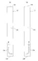
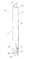
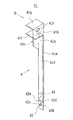
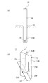
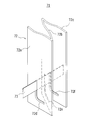
- FIG. 1 is a perspective view showing a pile according to a first embodiment of the present invention.
- FIG. 2 is an enlarged perspective view showing the tip side of the pile according to the first embodiment.
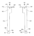
- 3A and 3B are side views showing the pile of the first embodiment when viewed from the two arrow directions A and B of FIG.
- the pile 11 of the first embodiment includes a pile body 12 and a plate-like member 13.
- the pile main body 12 is a columnar member formed of L-shaped steel having a cross-sectional shape of L, and has two wall portions 12 a and 12 b extending in the longitudinal direction of the pile main body 12.
- the respective groove portions 15a and 15b are formed in the respective wall portions 12a and 12b.
- Each slot 15a, 15b becomes longer in the longitudinal direction of the pile body 12 as it approaches the tip 12d side, which is the lower side when buried from the head 12c side, which is the upper side when the pile of the pile body 12 is buried. Smoothly bends and extends in a direction intersecting the longitudinal direction, and is generally J-shaped.
- Each slot 15a, 15b is formed in the site
- each slot 15a, 15b is relative to the virtual symmetry plane. It is formed in plane symmetry.
- each slot 15a, 15b is set constant.
- the periphery of each slot 15a, 15b is a circular arc.
- the peripheral edge of each slot 15a, 15b may be another curve such as an ellipse, a hyperbola, a parabola, or a bent line in which a plurality of straight lines or curves are continuous, and is bent almost smoothly.
- any kind of curve or bent line may be used.
- the peripheral edge of each groove hole 15a, 15b is directed in the horizontal direction or an inclined direction close to horizontal.
- the plate-like member 13 is a rectangular steel plate, has a width longer than the distance between the most separated portions of the slots 15a and 15b, and a thickness thinner than the width W of the slots 15a and 15b.
- the plate-like member 13 penetrates through each of the slots 15a and 15b while being movable along the slots 15a and 15b, and both side portions of the plate-like member 13 protrude to the outside of the walls 12a and 12b. Yes.
- the length and thickness of the pile main body 12 may be appropriately set according to the type of ground into which the pile main body 12 is driven, the structure of the formation or the driving length, that is, the usage state of the pile 11. Moreover, what is necessary is just to set the length and thickness of the plate-shaped member 13 suitably according to the size of the pile main body 12, and the use condition of the pile 11.
- FIG. 1 A first figure.
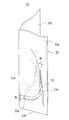
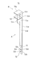
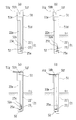
- FIG. 4 is a perspective view showing a pile according to a second embodiment of the present invention.
- FIG. 5 is an enlarged perspective view showing the tip side of the pile according to the second embodiment.
- 6 (a) and 6 (b) are side views showing the pile of the second embodiment as viewed from the two arrow directions A and B in FIG.
- the pile 21 according to the second embodiment of the present invention includes a pile body 22 and a plate-like member 23.
- the pile main body 22 is substantially the same shape as the pile main body 12 of the first embodiment described above, and the two wall portions 22a and 22b extending in the longitudinal direction of the pile main body 22 and the tip 22d side of the pile main body 22 And the respective J-shaped grooves 25a and 25b formed in the wall portions 22a and 22b.
- each slot 25a, 25b is formed by aligning the position in the longitudinal direction of the pile body 22 and aligning the direction of bending (the direction of J-shaped bending) on each wall 22a, 22b. Yes.
- each slot 25a, 25b of the pile main body 22 is different from the shape of each slot 15a, 15b of the pile main body 12 of 1st Embodiment, and the shape of the plate-shaped member 23 is 1st Embodiment.
- the shape of the plate-like member 13 is different.
- the width W of the groove holes 25a and 25b is constant, and the width W gradually increases as it approaches the end portion in the direction intersecting the longitudinal direction of the pile body 22 that is the lower end of each groove hole 25a and 25b from the middle part of the bending. Becomes narrower. Near the end of the pile body 22 in the direction intersecting the longitudinal direction, the width W of each slot 25a, 25b is substantially the same as the thickness of the plate member 23 or slightly wider than the thickness of the plate member 23. ing.
- the plate-like member 23 is formed by bending a rectangular steel plate in the same direction at two locations in the vicinity of both ends thereof, and has a flat plate-like central portion 23a and each bent portion 23b.
- the central part 23a is made longer than the distance between the most separated portions of the slots 25a and 25b.
- the plate-like member 23 penetrates through each of the groove holes 25a and 25b while being movable along each of the groove holes 25a and 25b, and both side portions of the central portion 23a and the bent portions 23b are formed on the wall portions 22a and 22b. Projects outward.
- the length and thickness of the pile main body 22 are appropriately set according to the usage status of the pile 21, and the length and thickness of the plate-like member 23 are appropriately set according to the size of the pile main body 22 and the usage status of the pile 21.
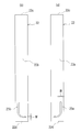
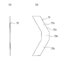
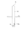
- FIG. 7A is a perspective view showing a pile according to a third embodiment of the present invention.
- FIG. 7B (a), (b) is the top view and sectional drawing which show the plate-shaped member in the pile of 3rd Embodiment.
- FIG. 8 is an enlarged perspective view showing the tip side of the pile according to the third embodiment.
- FIGS. 9A and 9B are side views showing the pile of the third embodiment when viewed from two arrow directions A and B in FIG. 7A.
- the pile 31 according to the third embodiment of the present invention includes a pile body 32 and a plate-like member 33.
- the pile main body 32 has substantially the same shape as the pile main body 12 of the first embodiment described above, and the two wall portions 32a and 32b extending in the longitudinal direction of the pile main body 32, and the tip 32d side of the pile main body 32 And each J-shaped slot 35a, 35b formed in each wall 32a, 32b.
- each slot 35a, 35b is formed in plane symmetry with respect to the virtual symmetry plane extended in the longitudinal direction of the pile main body 32 through the L-shaped corner
- each slot 35a, 35b of the pile main body 22 is different from the shape of each slot 15a, 15b of the pile main body 12 of 1st Embodiment, and the shape of the plate-shaped member 33 is 1st Embodiment. This is different from the shape of the plate-like member 13 of the pile body 12.
- the width W of each slot 35a, 35b is the direction in which each slot 35a, 35b intersects the longitudinal direction of the pile body 32 from the longitudinal end of the pile body 32 that is the upper end of each slot 35a, 35b.
- the thickness of the plate-like member 33 is substantially the same as or slightly larger than the thickness of the plate-like member 33 until the portion starts to bend smoothly.
- the width W of each of the groove holes 35 a and 35 b is gradually increased from a middle portion of the portion bent in the direction intersecting the longitudinal direction of the pile main body 32, and is constant sufficiently wider than the thickness of the plate-like member 33. If it becomes a width
- the plate member 33 is a substantially V-shaped steel plate, and has a rectangular center portion 33a and each arm portion 33b.
- the plate-like member 33 is made longer than the interval between the slots 35a and 35b that are the farthest apart.
- the plate-like member 33 penetrates through each of the groove holes 35a and 35b while being movable along the respective groove holes 35a and 35b, and both side portions of the plate-like member 33 protrude to the outside of the respective wall portions 32a and 32b. Yes.
- the length and thickness of the pile main body 32 are appropriately set according to the usage status of the pile 31, and the length and thickness of the plate-like member 33 are appropriately set according to the size of the pile main body 32 and the usage status of the pile 31.
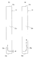
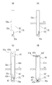
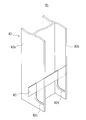
- FIG. 10 is a perspective view showing a pile installation jig according to a fourth embodiment of the present invention.
- 11 (a) and 11 (b) are side views showing the pile installation jig of the fourth embodiment of the present invention as viewed from the two arrow directions A and B in FIG.
- FIG. 12 is a plan view showing the pile installation jig of the fourth embodiment as viewed from above.
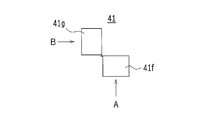
- the pile installation jig 41 of the fourth embodiment of the present invention connects two wall portions 41a, 41b in an L shape.
- L-shaped portion 41c, each arm portion 41d, 41e extending downward from the lower end of each wall portion 41a, 41b, and each top plate 41f bent outward at the upper end of each wall portion 41a, 41b, 41g.
- Each wall 41a, 41b is formed with a perforation 41h.
- the arm portions 41d and 41e are separated from each other, and the respective cutout portions 42 are formed on the sides near the lower ends of the arm portions 41d and 41e.
- Each notch 42 has an upper pressing side 42a, a side 42b, and a lower receiving side 42c.
- the pressing side 42a is slightly bent and inclined so as to face upward on the side side 42b, and the angle between the pressing side 42a and the side side 42b is made an acute angle.
- a holding space 42d is formed.
- Such a pile installation jig 41 of the fourth embodiment can be applied to any of the piles 11, 21, and 31 of the first to third embodiments described above. Moreover, what is necessary is just to set suitably the length and thickness of the jig 41 for pile installation according to the size and usage condition of the pile to which the jig 41 for pile installation is applied.
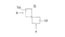
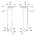
- FIG. 13 is a perspective view showing a pile installation jig according to a fifth embodiment of the present invention.
- FIGS. 14A and 14B are side views showing the pile installation jig of the fifth embodiment of the present invention as viewed from the two arrow directions A and B of FIG.
- FIG. 15 is a top view which shows the jig for pile installation of 5th Embodiment seeing from upper direction.
- tool 51 of 5th Embodiment of this invention is the pile installation jig
- the L-shaped part 51c which has a generally similar shape and connects the two wall parts 51a and 51b in an L-shape, and the arm parts 51d and 51e extended downward from the lower ends of the respective wall parts 51a and 51b.
- a perforation 51h is formed in each of the walls 51a and 51b.
- each notch 52 formed on the side near the lower end of each arm 51d, 51e is the shape formed on the side near the lower end of each arm 41d, 41e of the fourth embodiment.
- the shape of the notch 42 is different.
- Each notch 52 is formed continuously from the upper pressing side 52a, the side 52b, the lower receiving side 52c, and the pressing side 52a, and reaches the side of each arm 51d, 51e. And side 52e.
- the pressing side 52a is slightly bent and inclined so as to face upward on the side side 52b side, and the angle between the pressing side 52a and the side side 52b is made an acute angle.
- a holding space 52d is formed.
- the inclined side 52e is inclined so as to be separated from the pressing side 52a toward the direction intersecting the longitudinal direction of the pile installation jig 51 as it approaches the head of the pile installation jig 51.
- Such a pile installation jig 51 of the fifth embodiment can be applied to any of the piles 11, 21, and 31 of the first to third embodiments described above. Moreover, what is necessary is just to set the length and thickness of the jig 51 for pile installation suitably according to the size and usage condition of the pile to which the jig 51 for pile installation is applied.
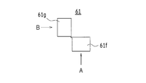
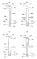
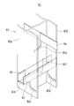
- FIG. 16 is a perspective view showing a pile installation jig according to a sixth embodiment of the present invention.
- FIGS. 17A and 17B are side views showing the pile installation jig of the sixth embodiment as viewed from the two arrow directions A and B in FIG. 16.
- FIG. 18 is a plan view showing the pile installation jig of the sixth embodiment as viewed from above.
- the pile installation jig 61 of the sixth embodiment is substantially the same as the pile installation jig 41 of the above-described fourth embodiment. And has an L-shaped portion 61c in which two wall portions 61a and 61b are connected in an L-shape, and respective top plates 61f and 61g bent outward at the upper ends of the respective wall portions 61a and 61b. ing.
- Each wall 61a, 61b is formed with a perforation 61h.
- the notch part 62 is formed in the lower end of each wall part 61a, 61b, respectively.
- the pile installation jig 61 does not include the arm portions 41d and 41e of the fourth embodiment, and the wall portions 61a and 61b are replaced with the arm portions 41d and 41e of the fourth embodiment. It is extended by the length of. Further, the shape of the notch 62 at the lower end of each wall 61a, 61b is different from the shape of each notch 42 formed on the side near the lower end of each arm 41d, 41e of the fourth embodiment. Yes.
- Each notch 62 has an upper pressing side 62a, a side 62b, and an inclined side 62e that is formed continuously with the pressing side 62a and reaches the side of each wall 61a, 61b. .
- the pressing side 62a is slightly bent and inclined so as to face upward on the side side 62b, and the angle between the pressing side 62a and the side side 62b is made an acute angle.
- a holding space 62d is formed.
- the inclined side 62e is inclined so as to be separated from the pressing side 62a toward the direction intersecting the longitudinal direction of the pile installation jig 61 as it approaches the head of the pile installation jig 61.
- each notch 62 is not provided with one corresponding to the receiving side 42c of the notch 42 in the fourth embodiment and the receiving side 52c of the notch 52 in the fifth embodiment.
- Such a pile installation jig 61 of the sixth embodiment can be applied to any of the piles 11, 21, and 31 of the first to third embodiments described above. Moreover, what is necessary is just to set the length and thickness of the jig 61 for pile installation suitably according to the size and usage condition of the pile to which the jig 61 for pile installation is applied.
- the installation method of the seventh embodiment of the present invention uses the pile installation jig 41 of the fourth embodiment shown in FIG. 10, FIG. 11 (a), (b), and FIG. This is a method of burying the pile 11 of the first embodiment shown in FIG. 2 and FIGS. 3 (a) and 3 (b) in the ground, as shown in FIGS. 19 (a) to 19 (d) and FIG. 20 (a). Implemented in each step shown.
- the plate-like member 13 passes through the slots 15a and 15b of the pile body 12, and both side portions of the plate-like member 13 protrude outside the wall portions 12a and 12b. It is in a state of letting it.
- the L-shaped portion 41c and the arm portions 41d and 41e of the pile installation jig 41 are superposed on the outside of the wall portions 12a and 12b of the pile body 12, and the wall portions 41a and 41b and the arm portions 41d are overlapped.
- 41 e are arranged along the longitudinal direction of the pile body 12, and both side portions of the plate-like member 13 protruding outside the wall portions 12 a, 12 b are connected to the arm portions of the pile installation jig 41.
- the pile 11 and the pile installation jig 41 are both driven into the ground as shown in FIG. 19B in a state where the pile 11 and the pile installation jig 41 are combined.
- the pile 11 and the pile installation jig 41 are driven by a hammer or the like attached to a heavy machine.
- the pile 11 and the pile installation jig 41 are prevented from being displaced from each other in the vertical direction, and the pile 11 and the pile
- the installation jig 41 can be driven into the ground at the same time.
- the pile installation jig 41 is driven deeper by the lengths of the grooves 15 a and 15 b of the pile body 12.
- the top plate 41f, 41g of the pile installation jig 41 is repeatedly struck with a hammer or the like, and the pile installation jig 41 is driven into the ground for pile installation.
- the pile installation jig 41 is driven into the ground by the length of each groove 15a, 15b of the pile body 12.
- the pile installation jig 41 Since both side portions of the plate-like member 13 are inserted into the cutout portions 42 of the arm portions 41 d and 41 e of the pile installation jig 41, the pile installation jig 41 is provided with the groove holes 15 a and 15 b of the pile body 12.
- the pressing side 42a of the notch portion 42 of the arm portion 41e extends from the head 12c side of the pile body 12 to the side ends 13a of both side portions of the plate-like member 13.
- the plate-like member 13 is pressed down and the plate-like member 13 moves along the grooves 15a and 15b.
- the plate-like member 13 can be surely pushed down. Then, the plate-like member 13 moves along the groove holes 15a and 15b in a direction intersecting the longitudinal direction of the pile body 12 (horizontal direction or inclined direction close to the horizontal), and further below the groove holes 15a and 15b. Stop at the end of the side. Thereby, the plate-like member 13 is sandwiched and supported by a portion where each of the groove holes 15a and 15b extends in a direction intersecting the longitudinal direction, that is, a portion near the lower end of each of the groove holes 15a and 15b.
- the pile installation jig 41 is pulled out from the ground.
- the pile installation jig 41 is pulled out by hooking a hook on each hole 41h of the pile installation jig 41 and pulling the hook up by a construction machine.
- the pile 11 is buried in the ground.
- the plate-like member 13 has moved to a portion of each slot 15a, 15b extending in a direction intersecting the longitudinal direction of the pile body 12.
- the plate-like member 13 is sandwiched and fixed in the vertical direction with respect to the pile body 12.
- the surface of the plate-like member 13 spreads in a substantially horizontal direction, and the resistance to the vertical movement of the plate-like member 13 is increased by earth and sand, so that the plate-like member 13 is difficult to move up and down in the ground. That is, the plate-like member 13 is fixed in the vertical direction with respect to the pile body 12, and the vertical movement of the plate-like member 13 is hindered by the earth and sand.
- strength and supporting force of the pile main body 12 can be made high.
- the angle formed by the surface of the plate-like member 13 with respect to the horizontal it is possible to expect further improvement in the pulling strength of the pile body 12. If the angle is 0 degree, that is, if the surface of the plate-like member 13 is horizontal, the pull-out strength is maximized. For this reason, in any embodiment, it describes so that the surface of the plate-shaped member 13 may become substantially horizontal. However, the surface of the plate-like member 13 does not have to be horizontal or substantially horizontal. Even if the angle formed by the surface of the plate-like member 13 with respect to the horizontal is appropriately changed together with the length, width, thickness, etc. of the plate-like member 13 in accordance with the installation depth of the pile body 12, the geology of the installation location, etc. Good.
- the said substantially horizontal assumes the state from which the angle which the surface of the plate-shaped member 13 makes with respect to horizontal will be 20 degrees or less. This is because the pull-out strength of the pile main body 12 is improved and the plate-like member 13 is moved from above to move the plate-like member 13 along the slots 15a and 15b. .
- the pile installation method of the seventh embodiment of the present invention is performed using the pile installation jig 51 of the fifth embodiment shown in FIGS. 13, 14 (a), (b), and FIG. 15. 4, FIG. 5 and FIGS. 6A and 6B can also be applied to the case where the pile 21 of the second embodiment shown in FIG. 6 is buried in the ground.
- the respective steps are shown in FIGS. 21 (a) to (d) and FIG.
- the wall portions 51a, 51b and the arm portions 51d, 51e of the pile installation jig 51 are overlapped on the outside of the wall portions 22a, 22b of the pile body 22, A long portion having the wall portions 51 a and 51 and the arm portions 51 d and 51 e is disposed along the longitudinal direction of the pile body 22.
- Both side portions of the plate-like member 23 projecting outside the wall portions 22a, 22b of the pile body 22 are put into the cutout portions 52 of the arm portions 51d, 51e of the pile installation jig 51, and the plate-like member 23
- the plate-like member 23 is held at a fixed position by placing both side portions on the receiving sides 52c of the cutout portions 52 of the arm portions 51d and 51e.
- the pile 21 and the pile installation jig 51 are both driven into the ground as shown in FIG. 21 (b) in a state where the pile 21 and the pile installation jig 51 are combined.
- the pile installation jig 51 is driven deeper by the lengths of the grooves 25 a and 25 b of the pile body 22.
- both side portions of the plate-like member 23 are put in the notches 52 of the arm portions 51d and 51e of the pile installation jig 51, when the pile installation jig 51 is driven deeper,
- the pressing sides 52a of the notches 52 of the arm portions 51d and 51e of the installation jig 51 come into contact with the side ends 23c of both side portions of the plate-like member 23 from the head 22c side of the pile body 22 to form a plate shape.
- the member 23 is pushed down, and the plate-like member 23 moves to the lower side in the longitudinal direction of the pile main body 22 along the respective slots 25a and 25b. Further, since the side ends 23c of the both side portions of the plate-like member 23 are held by the holding spaces 52d of the notches 52 of the arm portions 51d and 51e, the plate-like member 23 can be surely pushed down. And if the plate-shaped member 23 moves to the direction (horizontal direction or the inclination direction close
- the side edge 23c of the plate-like member 23 abuts from the pressing side 52a of each notch 52 to the inclined side 52e, and the inclined side 52e of each notch 52 is located on both sides of the plate-like member 23.
- the side end 23c is moved obliquely downward.
- the plate-like member 23 moves smoothly along the respective groove holes 25a, 25b, and the plate-like member 23 abuts against the lower end of each of the groove holes 25a, 25b and stops.
- the pile installation jig 51 is pulled out from the ground, and the pile 21 is buried in the ground.
- the plate-like member 23 penetrates the respective groove holes 25a and 25b of the pile main body 22 in a state where the respective bent portions 23b are bent upward, the plate-like member 23 is driven in the process of driving the pile main body 22 in. Since each bending part 23b receives resistance in the ground, the plate-shaped member 23 can rotate itself and can move smoothly along each J-shaped slot 25a, 25b.
- each bending part 23b of the plate-shaped member 23 protrudes to the outer side of each wall part 22a, 22b of the pile main body 22, even if the plate-shaped member 23 shifts in the lateral direction in the middle of driving the pile main body 22, One of the bent portions 23b of the plate-like member 23 comes into contact with any one of the wall portions 22a, 22b of the pile main body 22, and the plate-like member 23 is detached from the respective slot holes 25a, 25b of the pile main body 22. Can be suppressed.
- each slot 25a, 25b of the pile body 22 the width W of each slot 25a, 25b is substantially the same as the thickness of the plate-like member 23 or slightly wider than the thickness of the plate-like member 23. Therefore, when the plate-like member 23 comes into contact with the lower end of each slot 25a, 25b and stops, the plate-like member 23 does not rattle at a portion near the lower end of each slot 25a, 25b. It is caught. Further, the plate-like member 23 is firmly fixed because it holds earth and sand inside the flat plate-like central portion 23a and each bent portion 23b.
- the plate member 23 since the vertical movement of the plate member 23 relative to the pile body 22 can be more reliably suppressed, the plate member 23 is firmly fixed by the earth and sand. Thereby, the pulling-out strength and supporting force of the pile main body 22 can be made higher.
- the pile installation method of the eighth embodiment of the present invention uses the pile installation jig 61 of the sixth embodiment shown in FIG. 16, FIG. 17 (a), (b), and FIG. FIG. 7B, FIG. 8, and FIG. 9 (a) and FIG. 9 (b) show a method of embedding the pile 31 of the third embodiment in the ground, and each of the methods shown in FIG. 23 (a) to (d) and FIG. Implemented in the process.
- the plate-like member 33 is passed through the slots 35a, 35b of the pile body 32, and both side portions of the plate-like member 33 are projected to the outside of the wall portions 32a, 32b. In this state, the pile 31 is driven into the ground as shown in FIG. 23 (a).
- each wall part 61a, 61b of the jig 61 for pile installation is piled up on the outer side of each wall part 32a, 32b of the pile main body 32 of the pile 31 driven into the ground.
- the long portions having the wall portions 61a and 61b are arranged along the longitudinal direction of the pile main body 32, and the top plates 61f and 61g of the pile installation jig 61 are repeatedly struck for pile installation. The jig 61 is driven into the ground.
- each wall part 61a, 61b of the pile installation jig 61 is overlaid on the outside of each wall part 32a, 32b of the pile main body 32 in the ground, and each wall part 61a, 61b of the pile installation jig 61 is overlapped.
- the pressing side 62 a comes into contact with the side ends 33 c of both side portions of the plate-like member 33.
- the pile installation jig 61 is driven further deeper by the length of each slot 35a, 35b of the pile body 32. Since the pressing sides 62a of the wall portions 61a and 61b of the pile installation jig 61 are in contact with the side ends 33c of both side portions of the plate-like member 33, the pile installation jig 61 is driven deeper. The pressing side 62a of each wall 61a, 61b of the pile installation jig 61 pushes down the plate-like member 33, and the plate-like member 33 is located below the longitudinal direction of the pile main body 32 along each slot 35a, 35b. Moving.
- the side ends 33c of both side portions of the plate-like member 33 are held by the holding spaces 62d of the notches 62 of the respective wall portions 61a and 61b, and the plate-like member 33 is reliably pushed down.
- the plate-shaped member 33 begins to move in the direction (horizontal direction or the inclination direction close
- the contact portion of the side end 33 c of the plate-like member 33 with respect to the portion 62 shifts from the pressing side 62 a of each notch 62 to the inclined side 62 e, and the inclined side 62 e of each notch 62 is on the plate-like member 33 side.
- the end 33c is pushed downward and moved. Thereby, the plate-like member 33 is smoothly moved along the respective groove holes 35a and 35b, and the plate-like member 33 hits the lower end of each of the groove holes 35
- each slot 35a, 35b is smoothly bent from the upper start end of each slot 35a, 35b to the direction in which each slot 35a, 35b intersects the longitudinal direction of the pile body 22.
- the thickness is set to be substantially the same as the thickness of the plate-like member 33 or slightly wider than the thickness of the plate-like member 33.
- the plate-like member 33 when pressing down the plate-like member 33 by the pressing sides 62a of the wall portions 61a, 61b of the pile installation jig 61, the plate-like member 33 is suppressed from being shaken by the grooves 35a, 35b, The plate-like member 33 can be guided downward, the resistance received in the ground when the plate-like member 33 moves is reduced, and the plate-like member 33 is moved quickly along the respective slots 35a, 35b. Can do. Further, since the plate-like member 33 is V-shaped, the plate-like member 33 protrudes long outside the pile main body 32 substantially perpendicularly to the wall portions 32a, 32b of the pile main body 32, and protrudes outside thereof. Holds a lot of earth and sand at both ends and is firmly fixed. As a result, the pull-out strength and supporting force of the pile body 32 can be further increased by the plate-like member 33.
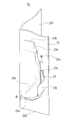
- a pile 71 according to the ninth embodiment of the present invention shown in FIG. 25 includes a pile main body 72 having a Z-shaped cross section and a plate-like member 73.
- the pile main body 72 has three wall parts 72a, 72b, 72c extending in the longitudinal direction of the pile main body 72, and the vicinity of the tip of each wall part 72a, 72b, 72c (near the tip of the pile main body 72).
- Each of the slots 72d, 72e, 72f is formed so that their positions coincide with each other in the longitudinal direction of the pile main body 72, and generally have a J shape, and their bending directions (J-shaped bending directions) are aligned.
- the rectangular plate-like member 73 is movable along the respective groove holes 72d, 72e, and 72f and penetrates the respective groove holes, and both side portions of the plate-like member 73 project outside the respective wall portions 72a and 72c. ing.
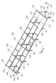
- a pile 81 according to a tenth embodiment of the present invention shown in FIG. 26A includes a pile body 82 having a H-shaped cross section and a plate-like member 83.
- the pile main body 82 has two wall portions 82a and 82b extending in the longitudinal direction of the pile main body 82 and facing each other, and in the vicinity of the front ends of the wall portions 82a and 82b (near the front end of the pile main body 82).
- the respective slots 82c and 82d are formed so that their positions coincide with each other in the longitudinal direction of the pile main body 82, and are substantially J-shaped and aligned in the direction of bending (the direction of J-shaped bending).
- the rectangular plate member 83 is movable along the groove holes 82c and 82d and passes through the groove holes, and both side portions of the plate member 83 protrude outside the wall portions 82a and 82b. ing.
- groove holes 82c and 82d not only one set of groove holes 82c and 82d, but another set of groove holes 82e and 82f are formed in the vicinity of the tips of the respective wall portions 82a and 82b, and other plate-like members 85 are provided. It is possible to move along the pair of slots 82e and 82f so as to penetrate each slot. Further, another slot 82g may be formed in the central wall connecting the walls 82a and 82b, and another plate member 86 may penetrate another slot 82g.
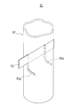
- a pile 91 according to an eleventh embodiment of the present invention includes a cylindrical pile body 92 and a plate-like member 93.
- a pair of groove holes 92 a and 92 b are formed in portions of the peripheral wall of the pile main body 92 facing each other.
- the slots 92a and 92b are formed so that their positions coincide with each other in the longitudinal direction of the pile main body 92, draw a generally J shape, and align their bending directions (J-shaped bending directions).
- the rectangular plate member 93 is movable along the respective groove holes 92 a and 92 b and penetrates the respective groove holes, and both side portions of the plate member 93 protrude outside the peripheral wall of the pile body 92.
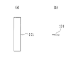
- 28 (a) and 28 (b) are a plan view and a cross-sectional view showing a modification of the plate member of the present invention.
- the plate-like member 101 of this modification has a rectangular shape when viewed from the top, and a wedge-shaped cross-sectional shape when viewed from the side, and has a blade shape.
- Such a wedge-shaped cross-sectional shape reduces the resistance received when the plate-like member 101 moves in the ground, so that the plate-like member 101 can be easily moved along the groove hole of the pile body.
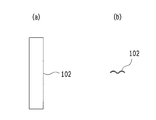
- FIGS. 29A and 29B are a plan view and a cross-sectional view showing another modification of the plate-like member of the present invention.
- the plate member 102 of another modification has a rectangular shape when viewed from the top, and a corrugated cross-sectional shape when viewed from the side.
- Such a corrugated cross-sectional shape increases the bending rigidity of the plate-like member 102, so that the pull-out strength and supporting force of the pile body can be increased. Further, the same effect can be obtained by applying a sawtooth cross-sectional shape instead of the wave shape.
- the plate-like member 104 of this another modified example is a plate-like member that comes into contact with the pushing side 42a (or the pushing sides 52a, 62a) of the pile installing jig 41 (or the pile installing jigs 51, 61).
- Two convex portions 104 a are provided at the side ends of 104.
- each arm portion 41d, 41e (or each arm portion 51d, 51e, each wall portion 61a, 61b) of the pile installation jig 41 (or pile installation jig 51, 61) is provided inside each convex portion 104a. It is possible to suppress the twisting and deformation of the arm portions 41d and 41e (or the arm portions 51d and 51e and the wall portions 61a and 61b) in the ground by being sandwiched.
- the plate-like member 105 of this still another modified example is in the form of a plate that abuts against the pressing side 42a (or the pressing sides 52a, 62a) of the pile installation jig 41 (or the pile installation jigs 51, 61).
- Two concave portions 105 a are provided at the side end of the member 105.
- the arm portions 41d and 41e (or the arm portions 51d and 51e and the wall portions 61a and 61b) of the pile installation jig 41 (or the pile installation jigs 51 and 61) are fitted inside the concave portions 105a.
- the piles of the above embodiments and the plate members of the above modifications may be appropriately combined or deformed.
- the width of the groove hole is set to be substantially the same as the thickness of the plate member or slightly wider than the thickness of the plate member, In the bent part of the slot, the width of the slot may be made sufficiently wider than the thickness of the plate member.
- a non-hollow square columnar or cylindrical shape may be applied as the pile body, and one pile hole may be provided in the pile body, and the plate member may be penetrated through the groove hole.
- the pile installation jig After moving the plate-shaped member along the groove hole of the pile body using the pile installation jig, leave the pile installation jig in the ground without removing it, and place the pile installation jig on the pile body. It may be used as a reinforcing member.
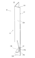
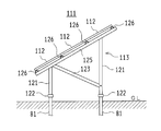
- FIG. 32 is a perspective view showing the solar power generation system according to the twelfth embodiment of the present invention.
- FIG. 33 is a rear view showing the solar power generation system of the twelfth embodiment, and
- FIG. 34 is a side view showing the solar power generation system.
- a pedestal 113 that supports a large number of solar cell modules 112 is fixed using a pile 81 of the tenth embodiment shown in FIG. is doing.
- the solar cell modules 112 are arranged in the east-west direction and the north-south direction, and the solar cell modules 112 are inclined toward the incident direction of sunlight. Moreover, you may apply the pile of other each embodiment and various modifications instead of the pile 81. FIG.
- a plurality of piles 81 are arranged at a first specified interval in the east-west direction and at a second specified interval in the north-south direction.
- the base 113 is fixed and supported on the upper end of each pile 81.
- the gantry 113 is adjacent to each column 121 provided on the extension of each pile 81, and each connection unit 122 for connecting and fixing each column 121 to the upper end of each pile 81 in the north-south direction.
- a brace 123 which is a reinforcing member stretched between the supporting columns 121, and a reinforcing member stretched between the supporting columns 121, which are adjacent to each other in the east-west direction.
- the braces 124 and the columns 121 adjacent to each other in the north-south direction are supported side by side on a vertical beam 125 spanning the upper ends of the columns 121 and a plurality of vertical beams 125 arranged in the east-west direction, and extend in the east-west direction.
- four horizontal rails 126 are supported side by side on a vertical beam 125 spanning the upper ends of the columns 121 and a plurality of vertical beams 125 arranged in the east-west direction, and extend in the east-west direction.
- four horizontal rails 126 are provided to each
- a plurality of solar cell modules 112 are mounted side by side between two adjacent horizontal beams 126, and a plurality of solar cell modules 112 are mounted on four horizontal beams 126. It is mounted side by side.
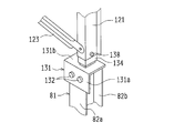
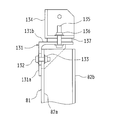
- FIG. 35 is a perspective view showing a connection unit 122 for connecting and fixing the column 121 to the upper end of the pile 81.
- FIG. FIG. 36 is a cross-sectional view showing the connection unit 122.
- the connection unit 122 includes an L-shaped attachment 131 and a joint member 134.
- the L-shaped attachment 131 is placed on the upper end of the pile 81, and the side wall portion 131a of the L-shaped attachment 131 is overlapped on one of the two opposing wall portions 82a and 82b of the pile 81, and two sets of bolts 132 and Using the nut 133, the side wall 131 a of the L-shaped attachment 131 is fixed to one of the wall portions 82 a and 82 b of the pile 81.
- joint member 134 is placed on the upper wall portion 131b of the L-shaped attachment 131, and the joint member 134 is attached to the upper wall portion 131b of the L-shaped attachment 131 using a set of bolts 135, nuts 136, and spacers 137. Fix it.
- the joint member 134 is inserted into the inside of the column 121, the bolt 138 is passed through the holes of the column 121 and the joint member 134, and a nut is screwed into the tip of the bolt 138 and tightened. Thereby, the support column 121 is connected and fixed to the upper end of the pile 81.
- the pile (pile 11) of the above embodiment is a pile buried in the ground, and is formed in a columnar pile body (pile body 12) and the pile body, and the upper side when the pile body is buried. From the longitudinal direction of the pile body toward the lower side, the groove hole (groove hole 15a) bent and extended in a direction intersecting the longitudinal direction, and a plate-like member (plate-like member) inserted into the groove hole 13).
- a plate-like member is inserted into the groove hole of the pile body, and the pile body is driven into the ground.
- the plate-like member is pushed down using a jig or the like, the plate-like member moves in the ground along the groove hole.
- the groove hole is bent and extended from the upper side to the lower side of the pile body in the direction intersecting the longitudinal direction from the upper side when the pile body is buried. It is sandwiched and supported by a portion extending in a direction crossing the longitudinal direction of the slot.
- the movement of the plate member in the pulling direction (upward in the longitudinal direction) of the pile body is prohibited by the portion extending in the direction intersecting the longitudinal direction of the pile body of the groove hole, and the plate member is Since it is fixed, the pulling-out strength and supporting force of the pile body can be increased.
- each said groove hole is provided with two or more, and each said groove hole (each groove hole 15a, 15b) is the direction of the said bending in each site
- each groove hole is formed in plane symmetry with respect to a virtual symmetry plane extending between the groove holes in the longitudinal direction of the pile body. ing.
- the pile body is driven into the ground with the plate-like member passing through the plurality of slots in the pile body, the plate-like member is pushed down, and the plate-like member moves along each slot. And are supported by being sandwiched between portions extending in a direction intersecting the longitudinal direction of each slot. Accordingly, a plurality of portions of the plate-like member are sandwiched and supported by the respective groove holes, the plate-like member is more firmly supported, and the pulling strength and supporting force of the pile body are further increased.
- the said pile main body has several wall part (each wall part 12a, 12b) extended in the longitudinal direction of the said pile main body, and each said slot is formed in each said wall part, respectively. Has been.
- the pile body when L-shaped steel is used as the pile body, the pile body has two wall parts, and when H-shaped steel is used as the pile body, the pile body has three wall parts. Each slot is formed in these wall parts.
- variety of the said groove hole is varied according to the position of this groove hole.
- the plate-like member is moved when the plate-like member is moved to the portion along the slot.
- the support of the pile body is further improved by being pinched at that part of the slot without rattling.
- the cross-sectional shape of the plate-like member is a wedge shape.
- the cross-sectional shape of such a plate-like member can reduce the resistance received when the plate-like member is moved in the ground, the plate-like member can be easily moved along the slot.
- the pile installation jig (pile installation jig 41) of the above-described embodiment is a pile installation jig used when installing a pile, and the longitudinal direction of the pile body of the pile to be installed When applying a downward force in the longitudinal direction to the long portions (the respective wall portions 41a and 41b, the respective arm portions 41d and 41e) disposed along the upper portion of the pile installation jig, from the pile main body, It has a pressing part (pressing side 42a) which abuts on the protruding member and can press the member in a direction inclined from the longitudinal direction of the pile body.
- the pressing portion abuts against a member protruding from the pile body from above when the pile body is buried. Furthermore, when the pile installation jig is driven, the member is pushed down by the pressing portion.
- tool of the said embodiment forms continuously in the said pressing part, and it is spaced apart from the said pressing part in the direction which cross
- An inclined portion (inclined side 52e) is provided. In this case, the member is pushed downward by the pressing portion, and then the member is pushed obliquely downward by the inclined portion.
- the pile installation jig of the above embodiment includes a receiving portion (receiving side 42c) that faces the pressing portion with the member interposed therebetween and receives the member. In this case, the member is held between the pressing portion and the receiving portion.
- the pile installation method of the above embodiment is a process of driving the pile main body into the ground, driving a pile installation jig into the ground, from the upper side to the lower side when the pile main body is buried, And a step of moving a plate-like member inserted into a groove hole that is bent and extended from a longitudinal direction of the pile body to a direction intersecting the longitudinal direction.
- the pile body is driven into the ground, the pile installation jig is driven into the ground, and the plate-like member is pushed down by the pile installation jig and moved along the groove hole.
- the pile installation method of the above embodiment includes a step of driving the pile main body and the pile installation jig together into the ground, and further driving the pile installation jig into the ground from the installation position of the pile main body.
- the plate-like member inserted in the groove hole that is bent and extended from the longitudinal direction of the pile body to the direction intersecting the longitudinal direction is moved from the upper side to the lower side when the pile body is buried. Process.
- the pile installation method of the above embodiment includes a step of pulling out the installation jig from the ground.
- the photovoltaic power generation system of the above embodiment includes a pile, a gantry constructed on the stake, and a plurality of solar cell modules supported on the gantry, and the pile is a columnar pile.
Landscapes
- Engineering & Computer Science (AREA)
- General Engineering & Computer Science (AREA)
- Life Sciences & Earth Sciences (AREA)
- Structural Engineering (AREA)
- Mechanical Engineering (AREA)
- Thermal Sciences (AREA)
- Chemical & Material Sciences (AREA)
- Combustion & Propulsion (AREA)
- Physics & Mathematics (AREA)
- Sustainable Energy (AREA)
- Sustainable Development (AREA)
- General Life Sciences & Earth Sciences (AREA)
- Mining & Mineral Resources (AREA)
- Paleontology (AREA)
- Civil Engineering (AREA)
- Piles And Underground Anchors (AREA)
- Placing Or Removing Of Piles Or Sheet Piles, Or Accessories Thereof (AREA)
- Photovoltaic Devices (AREA)
- Road Signs Or Road Markings (AREA)
Priority Applications (2)
| Application Number | Priority Date | Filing Date | Title |
|---|---|---|---|
| US14/917,392 US20160218659A1 (en) | 2013-09-09 | 2014-08-21 | Pile, pile installation jig, method for installing the pile, and photovoltaic system using the piles |
| CN201490001096.7U CN205822180U (zh) | 2013-09-09 | 2014-08-21 | 桩、桩设置用工具以及使用该桩的太阳能发电系统 |
Applications Claiming Priority (2)
| Application Number | Priority Date | Filing Date | Title |
|---|---|---|---|
| JP2013186304A JP6033191B2 (ja) | 2013-09-09 | 2013-09-09 | 杭、杭設置用治具、その杭の設置方法、及びその杭を用いた太陽光発電システム |
| JP2013-186304 | 2013-09-09 |
Publications (1)
| Publication Number | Publication Date |
|---|---|
| WO2015033784A1 true WO2015033784A1 (ja) | 2015-03-12 |
Family
ID=52628262
Family Applications (1)
| Application Number | Title | Priority Date | Filing Date |
|---|---|---|---|
| PCT/JP2014/071826 Ceased WO2015033784A1 (ja) | 2013-09-09 | 2014-08-21 | 杭、杭設置用治具、その杭の設置方法、及びその杭を用いた太陽光発電システム |
Country Status (4)
| Country | Link |
|---|---|
| US (1) | US20160218659A1 (enExample) |
| JP (1) | JP6033191B2 (enExample) |
| CN (1) | CN205822180U (enExample) |
| WO (1) | WO2015033784A1 (enExample) |
Cited By (1)
| Publication number | Priority date | Publication date | Assignee | Title |
|---|---|---|---|---|
| CN111455984A (zh) * | 2020-04-22 | 2020-07-28 | 中交第二航务工程局有限公司 | 一种桩基护桩及施工方法 |
Families Citing this family (5)
| Publication number | Priority date | Publication date | Assignee | Title |
|---|---|---|---|---|
| US10378171B2 (en) * | 2016-09-27 | 2019-08-13 | American Transmission Company LLC | Method and apparatus for improved installation of caissons |
| WO2023060318A1 (en) * | 2021-10-15 | 2023-04-20 | Solar Pile International (Us) Llc | Method for installing piles |
| US12480272B2 (en) | 2022-02-18 | 2025-11-25 | American Transmission Company LLC | Electrical pole with H-web caisson |
| EP4584881A1 (en) * | 2022-09-06 | 2025-07-16 | The AES Corporation | Field factory for solar panel pre-assembly |
| CN117684595B (zh) * | 2024-02-02 | 2024-05-14 | 寿光鸿海电力有限公司 | 一种滩涂光伏发电站建造方法 |
Citations (6)
| Publication number | Priority date | Publication date | Assignee | Title |
|---|---|---|---|---|
| JPS5526325A (en) * | 1978-08-09 | 1980-02-25 | Hitachi Zosen Corp | Steel-pipe pile |
| JPS6045739U (ja) * | 1983-09-03 | 1985-03-30 | 山本 明雄 | 杭体 |
| JP2010135632A (ja) * | 2008-12-05 | 2010-06-17 | Sharp Corp | 構造物設置架台、及び太陽電池システム |
| JP3176859U (ja) * | 2012-04-26 | 2012-07-05 | 株式会社イスズ | 太陽電池パネルユニット設置用架台の支柱、及び太陽電池パネルユニット設置用架台 |
| JP2013092024A (ja) * | 2011-10-27 | 2013-05-16 | Ogasawara Sekkei:Kk | 回転支圧体付きアースアンカーを用いた工作物または建造物の固定装置と工法 |
| JP2013253372A (ja) * | 2012-06-05 | 2013-12-19 | Something:Kk | 鋼管杭用組立羽根部材、鋼管杭、複合杭及び複合杭の製造方法 |
-
2013
- 2013-09-09 JP JP2013186304A patent/JP6033191B2/ja active Active
-
2014
- 2014-08-21 WO PCT/JP2014/071826 patent/WO2015033784A1/ja not_active Ceased
- 2014-08-21 CN CN201490001096.7U patent/CN205822180U/zh not_active Expired - Fee Related
- 2014-08-21 US US14/917,392 patent/US20160218659A1/en not_active Abandoned
Patent Citations (6)
| Publication number | Priority date | Publication date | Assignee | Title |
|---|---|---|---|---|
| JPS5526325A (en) * | 1978-08-09 | 1980-02-25 | Hitachi Zosen Corp | Steel-pipe pile |
| JPS6045739U (ja) * | 1983-09-03 | 1985-03-30 | 山本 明雄 | 杭体 |
| JP2010135632A (ja) * | 2008-12-05 | 2010-06-17 | Sharp Corp | 構造物設置架台、及び太陽電池システム |
| JP2013092024A (ja) * | 2011-10-27 | 2013-05-16 | Ogasawara Sekkei:Kk | 回転支圧体付きアースアンカーを用いた工作物または建造物の固定装置と工法 |
| JP3176859U (ja) * | 2012-04-26 | 2012-07-05 | 株式会社イスズ | 太陽電池パネルユニット設置用架台の支柱、及び太陽電池パネルユニット設置用架台 |
| JP2013253372A (ja) * | 2012-06-05 | 2013-12-19 | Something:Kk | 鋼管杭用組立羽根部材、鋼管杭、複合杭及び複合杭の製造方法 |
Cited By (1)
| Publication number | Priority date | Publication date | Assignee | Title |
|---|---|---|---|---|
| CN111455984A (zh) * | 2020-04-22 | 2020-07-28 | 中交第二航务工程局有限公司 | 一种桩基护桩及施工方法 |
Also Published As
| Publication number | Publication date |
|---|---|
| CN205822180U (zh) | 2016-12-21 |
| JP2015052245A (ja) | 2015-03-19 |
| US20160218659A1 (en) | 2016-07-28 |
| JP6033191B2 (ja) | 2016-11-30 |
Similar Documents
| Publication | Publication Date | Title |
|---|---|---|
| JP6033191B2 (ja) | 杭、杭設置用治具、その杭の設置方法、及びその杭を用いた太陽光発電システム | |
| JP6166908B2 (ja) | 太陽電池パネルの架台支持用支柱 | |
| KR102134462B1 (ko) | 지붕 설치용 태양광 발전장치의 지지프레임 고정구조체 | |
| US20110067749A1 (en) | Solar array support structure | |
| US20090193750A1 (en) | Construction Clip For Joining Structural Infrastructure | |
| JP5433733B2 (ja) | 基礎杭 | |
| JP5451549B2 (ja) | 連結金具 | |
| CN106661854A (zh) | 锚桩及其设置方法 | |
| KR20210015490A (ko) | 프리스트레스트 엄지말뚝을 이용한 2열 자립식 흙막이 공법 | |
| KR101542602B1 (ko) | 건축용 가설 흙막이시설 | |
| JP2017225276A (ja) | 太陽光発電パネル用固定具 | |
| KR102116111B1 (ko) | 토류벽의 흙막이용 패널조립체 | |
| US7594782B2 (en) | Integral retaining foot for rammed post or pole | |
| JP3181778U (ja) | 太陽光発電パネル支持架台 | |
| KR102110577B1 (ko) | 내진 흙막이 구조체 | |
| JP2009228242A (ja) | 防護柵の補強方法 | |
| KR20110078445A (ko) | 띠장 연결장치 | |
| KR20210011688A (ko) | 연약 지반용 주면 지지 파일 | |
| JP2014180195A (ja) | 骨組構造体 | |
| KR102116112B1 (ko) | 흙막이 토류벽체의 시공방법 | |
| CN212613377U (zh) | 钢管束构组件以及钢管束构装置 | |
| JP2007247308A (ja) | 斜杭からなる組杭の引き抜き耐力増強工法及び同工法よりなる構造 | |
| JP5699180B2 (ja) | ソーラーパネル用架台の構築方法 | |
| KR101414053B1 (ko) | Phc 말뚝의 천공장치 및 이를 이용한 phc 말뚝의 두부 보강방법 | |
| JP6091212B2 (ja) | くさび着脱機構、くさび着脱工具及びこれを用いたくさび着脱方法 |
Legal Events
| Date | Code | Title | Description |
|---|---|---|---|
| 121 | Ep: the epo has been informed by wipo that ep was designated in this application |
Ref document number: 14843075 Country of ref document: EP Kind code of ref document: A1 |
|
| WWE | Wipo information: entry into national phase |
Ref document number: 14917392 Country of ref document: US |
|
| NENP | Non-entry into the national phase |
Ref country code: DE |
|
| WWE | Wipo information: entry into national phase |
Ref document number: IDP00201602371 Country of ref document: ID |
|
| 122 | Ep: pct application non-entry in european phase |
Ref document number: 14843075 Country of ref document: EP Kind code of ref document: A1 |