WO2015033728A1 - 溝付き樹脂成形品、複合成形品、並びに複合成形品の製造方法 - Google Patents
溝付き樹脂成形品、複合成形品、並びに複合成形品の製造方法 Download PDFInfo
- Publication number
- WO2015033728A1 WO2015033728A1 PCT/JP2014/070687 JP2014070687W WO2015033728A1 WO 2015033728 A1 WO2015033728 A1 WO 2015033728A1 JP 2014070687 W JP2014070687 W JP 2014070687W WO 2015033728 A1 WO2015033728 A1 WO 2015033728A1
- Authority
- WO
- WIPO (PCT)
- Prior art keywords
- molded product
- resin molded
- resin
- inorganic filler
- groove
- Prior art date
- Legal status (The legal status is an assumption and is not a legal conclusion. Google has not performed a legal analysis and makes no representation as to the accuracy of the status listed.)
- Ceased
Links
Images




Classifications
-
- B—PERFORMING OPERATIONS; TRANSPORTING
- B29—WORKING OF PLASTICS; WORKING OF SUBSTANCES IN A PLASTIC STATE IN GENERAL
- B29C—SHAPING OR JOINING OF PLASTICS; SHAPING OF MATERIAL IN A PLASTIC STATE, NOT OTHERWISE PROVIDED FOR; AFTER-TREATMENT OF THE SHAPED PRODUCTS, e.g. REPAIRING
- B29C37/00—Component parts, details, accessories or auxiliary operations, not covered by group B29C33/00 or B29C35/00
- B29C37/0078—Measures or configurations for obtaining anchoring effects in the contact areas between layers
- B29C37/0082—Mechanical anchoring
-
- B—PERFORMING OPERATIONS; TRANSPORTING
- B29—WORKING OF PLASTICS; WORKING OF SUBSTANCES IN A PLASTIC STATE IN GENERAL
- B29C—SHAPING OR JOINING OF PLASTICS; SHAPING OF MATERIAL IN A PLASTIC STATE, NOT OTHERWISE PROVIDED FOR; AFTER-TREATMENT OF THE SHAPED PRODUCTS, e.g. REPAIRING
- B29C45/00—Injection moulding, i.e. forcing the required volume of moulding material through a nozzle into a closed mould; Apparatus therefor
- B29C45/14—Injection moulding, i.e. forcing the required volume of moulding material through a nozzle into a closed mould; Apparatus therefor incorporating preformed parts or layers, e.g. injection moulding around inserts or for coating articles
- B29C45/14311—Injection moulding, i.e. forcing the required volume of moulding material through a nozzle into a closed mould; Apparatus therefor incorporating preformed parts or layers, e.g. injection moulding around inserts or for coating articles using means for bonding the coating to the articles
-
- B—PERFORMING OPERATIONS; TRANSPORTING
- B29—WORKING OF PLASTICS; WORKING OF SUBSTANCES IN A PLASTIC STATE IN GENERAL
- B29C—SHAPING OR JOINING OF PLASTICS; SHAPING OF MATERIAL IN A PLASTIC STATE, NOT OTHERWISE PROVIDED FOR; AFTER-TREATMENT OF THE SHAPED PRODUCTS, e.g. REPAIRING
- B29C59/00—Surface shaping of articles, e.g. embossing; Apparatus therefor
- B29C59/16—Surface shaping of articles, e.g. embossing; Apparatus therefor by wave energy or particle radiation, e.g. infrared heating
-
- B—PERFORMING OPERATIONS; TRANSPORTING
- B29—WORKING OF PLASTICS; WORKING OF SUBSTANCES IN A PLASTIC STATE IN GENERAL
- B29C—SHAPING OR JOINING OF PLASTICS; SHAPING OF MATERIAL IN A PLASTIC STATE, NOT OTHERWISE PROVIDED FOR; AFTER-TREATMENT OF THE SHAPED PRODUCTS, e.g. REPAIRING
- B29C65/00—Joining or sealing of preformed parts, e.g. welding of plastics materials; Apparatus therefor
- B29C65/02—Joining or sealing of preformed parts, e.g. welding of plastics materials; Apparatus therefor by heating, with or without pressure
-
- B—PERFORMING OPERATIONS; TRANSPORTING
- B29—WORKING OF PLASTICS; WORKING OF SUBSTANCES IN A PLASTIC STATE IN GENERAL
- B29C—SHAPING OR JOINING OF PLASTICS; SHAPING OF MATERIAL IN A PLASTIC STATE, NOT OTHERWISE PROVIDED FOR; AFTER-TREATMENT OF THE SHAPED PRODUCTS, e.g. REPAIRING
- B29C65/00—Joining or sealing of preformed parts, e.g. welding of plastics materials; Apparatus therefor
- B29C65/82—Testing the joint
- B29C65/8253—Testing the joint by the use of waves or particle radiation, e.g. visual examination, scanning electron microscopy, or X-rays
-
- B—PERFORMING OPERATIONS; TRANSPORTING
- B29—WORKING OF PLASTICS; WORKING OF SUBSTANCES IN A PLASTIC STATE IN GENERAL
- B29C—SHAPING OR JOINING OF PLASTICS; SHAPING OF MATERIAL IN A PLASTIC STATE, NOT OTHERWISE PROVIDED FOR; AFTER-TREATMENT OF THE SHAPED PRODUCTS, e.g. REPAIRING
- B29C66/00—General aspects of processes or apparatus for joining preformed parts
- B29C66/01—General aspects dealing with the joint area or with the area to be joined
- B29C66/05—Particular design of joint configurations
- B29C66/10—Particular design of joint configurations particular design of the joint cross-sections
- B29C66/12—Joint cross-sections combining only two joint-segments; Tongue and groove joints; Tenon and mortise joints; Stepped joint cross-sections
- B29C66/128—Stepped joint cross-sections
- B29C66/1282—Stepped joint cross-sections comprising at least one overlap joint-segment
-
- B—PERFORMING OPERATIONS; TRANSPORTING
- B29—WORKING OF PLASTICS; WORKING OF SUBSTANCES IN A PLASTIC STATE IN GENERAL
- B29C—SHAPING OR JOINING OF PLASTICS; SHAPING OF MATERIAL IN A PLASTIC STATE, NOT OTHERWISE PROVIDED FOR; AFTER-TREATMENT OF THE SHAPED PRODUCTS, e.g. REPAIRING
- B29C66/00—General aspects of processes or apparatus for joining preformed parts
- B29C66/01—General aspects dealing with the joint area or with the area to be joined
- B29C66/05—Particular design of joint configurations
- B29C66/10—Particular design of joint configurations particular design of the joint cross-sections
- B29C66/12—Joint cross-sections combining only two joint-segments; Tongue and groove joints; Tenon and mortise joints; Stepped joint cross-sections
- B29C66/128—Stepped joint cross-sections
- B29C66/1284—Stepped joint cross-sections comprising at least one butt joint-segment
- B29C66/12841—Stepped joint cross-sections comprising at least one butt joint-segment comprising at least two butt joint-segments
-
- B—PERFORMING OPERATIONS; TRANSPORTING
- B29—WORKING OF PLASTICS; WORKING OF SUBSTANCES IN A PLASTIC STATE IN GENERAL
- B29C—SHAPING OR JOINING OF PLASTICS; SHAPING OF MATERIAL IN A PLASTIC STATE, NOT OTHERWISE PROVIDED FOR; AFTER-TREATMENT OF THE SHAPED PRODUCTS, e.g. REPAIRING
- B29C66/00—General aspects of processes or apparatus for joining preformed parts
- B29C66/01—General aspects dealing with the joint area or with the area to be joined
- B29C66/05—Particular design of joint configurations
- B29C66/10—Particular design of joint configurations particular design of the joint cross-sections
- B29C66/14—Particular design of joint configurations particular design of the joint cross-sections the joint having the same thickness as the thickness of the parts to be joined
-
- B—PERFORMING OPERATIONS; TRANSPORTING
- B29—WORKING OF PLASTICS; WORKING OF SUBSTANCES IN A PLASTIC STATE IN GENERAL
- B29C—SHAPING OR JOINING OF PLASTICS; SHAPING OF MATERIAL IN A PLASTIC STATE, NOT OTHERWISE PROVIDED FOR; AFTER-TREATMENT OF THE SHAPED PRODUCTS, e.g. REPAIRING
- B29C66/00—General aspects of processes or apparatus for joining preformed parts
- B29C66/01—General aspects dealing with the joint area or with the area to be joined
- B29C66/05—Particular design of joint configurations
- B29C66/303—Particular design of joint configurations the joint involving an anchoring effect
- B29C66/3032—Particular design of joint configurations the joint involving an anchoring effect making use of protrusions or cavities belonging to at least one of the parts to be joined
- B29C66/30325—Particular design of joint configurations the joint involving an anchoring effect making use of protrusions or cavities belonging to at least one of the parts to be joined making use of cavities belonging to at least one of the parts to be joined
-
- B—PERFORMING OPERATIONS; TRANSPORTING
- B29—WORKING OF PLASTICS; WORKING OF SUBSTANCES IN A PLASTIC STATE IN GENERAL
- B29C—SHAPING OR JOINING OF PLASTICS; SHAPING OF MATERIAL IN A PLASTIC STATE, NOT OTHERWISE PROVIDED FOR; AFTER-TREATMENT OF THE SHAPED PRODUCTS, e.g. REPAIRING
- B29C66/00—General aspects of processes or apparatus for joining preformed parts
- B29C66/01—General aspects dealing with the joint area or with the area to be joined
- B29C66/05—Particular design of joint configurations
- B29C66/303—Particular design of joint configurations the joint involving an anchoring effect
- B29C66/3034—Particular design of joint configurations the joint involving an anchoring effect making use of additional elements, e.g. meshes
-
- B—PERFORMING OPERATIONS; TRANSPORTING
- B29—WORKING OF PLASTICS; WORKING OF SUBSTANCES IN A PLASTIC STATE IN GENERAL
- B29C—SHAPING OR JOINING OF PLASTICS; SHAPING OF MATERIAL IN A PLASTIC STATE, NOT OTHERWISE PROVIDED FOR; AFTER-TREATMENT OF THE SHAPED PRODUCTS, e.g. REPAIRING
- B29C66/00—General aspects of processes or apparatus for joining preformed parts
- B29C66/70—General aspects of processes or apparatus for joining preformed parts characterised by the composition, physical properties or the structure of the material of the parts to be joined; Joining with non-plastics material
- B29C66/72—General aspects of processes or apparatus for joining preformed parts characterised by the composition, physical properties or the structure of the material of the parts to be joined; Joining with non-plastics material characterised by the structure of the material of the parts to be joined
- B29C66/721—Fibre-reinforced materials
- B29C66/7214—Fibre-reinforced materials characterised by the length of the fibres
- B29C66/72143—Fibres of discontinuous lengths
-
- B—PERFORMING OPERATIONS; TRANSPORTING
- B32—LAYERED PRODUCTS
- B32B—LAYERED PRODUCTS, i.e. PRODUCTS BUILT-UP OF STRATA OF FLAT OR NON-FLAT, e.g. CELLULAR OR HONEYCOMB, FORM
- B32B27/00—Layered products comprising a layer of synthetic resin
- B32B27/06—Layered products comprising a layer of synthetic resin as the main or only constituent of a layer, which is next to another layer of the same or of a different material
- B32B27/08—Layered products comprising a layer of synthetic resin as the main or only constituent of a layer, which is next to another layer of the same or of a different material of synthetic resin
-
- B—PERFORMING OPERATIONS; TRANSPORTING
- B32—LAYERED PRODUCTS
- B32B—LAYERED PRODUCTS, i.e. PRODUCTS BUILT-UP OF STRATA OF FLAT OR NON-FLAT, e.g. CELLULAR OR HONEYCOMB, FORM
- B32B27/00—Layered products comprising a layer of synthetic resin
- B32B27/18—Layered products comprising a layer of synthetic resin characterised by the use of special additives
- B32B27/20—Layered products comprising a layer of synthetic resin characterised by the use of special additives using fillers, pigments, thixotroping agents
-
- B—PERFORMING OPERATIONS; TRANSPORTING
- B32—LAYERED PRODUCTS
- B32B—LAYERED PRODUCTS, i.e. PRODUCTS BUILT-UP OF STRATA OF FLAT OR NON-FLAT, e.g. CELLULAR OR HONEYCOMB, FORM
- B32B3/00—Layered products comprising a layer with external or internal discontinuities or unevennesses, or a layer of non-planar shape; Layered products comprising a layer having particular features of form
- B32B3/26—Layered products comprising a layer with external or internal discontinuities or unevennesses, or a layer of non-planar shape; Layered products comprising a layer having particular features of form characterised by a particular shape of the outline of the cross-section of a continuous layer; characterised by a layer with cavities or internal voids ; characterised by an apertured layer
- B32B3/30—Layered products comprising a layer with external or internal discontinuities or unevennesses, or a layer of non-planar shape; Layered products comprising a layer having particular features of form characterised by a particular shape of the outline of the cross-section of a continuous layer; characterised by a layer with cavities or internal voids ; characterised by an apertured layer characterised by a layer formed with recesses or projections, e.g. hollows, grooves, protuberances, ribs
-
- B—PERFORMING OPERATIONS; TRANSPORTING
- B29—WORKING OF PLASTICS; WORKING OF SUBSTANCES IN A PLASTIC STATE IN GENERAL
- B29C—SHAPING OR JOINING OF PLASTICS; SHAPING OF MATERIAL IN A PLASTIC STATE, NOT OTHERWISE PROVIDED FOR; AFTER-TREATMENT OF THE SHAPED PRODUCTS, e.g. REPAIRING
- B29C45/00—Injection moulding, i.e. forcing the required volume of moulding material through a nozzle into a closed mould; Apparatus therefor
- B29C45/14—Injection moulding, i.e. forcing the required volume of moulding material through a nozzle into a closed mould; Apparatus therefor incorporating preformed parts or layers, e.g. injection moulding around inserts or for coating articles
- B29C45/14311—Injection moulding, i.e. forcing the required volume of moulding material through a nozzle into a closed mould; Apparatus therefor incorporating preformed parts or layers, e.g. injection moulding around inserts or for coating articles using means for bonding the coating to the articles
- B29C2045/14327—Injection moulding, i.e. forcing the required volume of moulding material through a nozzle into a closed mould; Apparatus therefor incorporating preformed parts or layers, e.g. injection moulding around inserts or for coating articles using means for bonding the coating to the articles anchoring by forcing the material to pass through a hole in the article
-
- B—PERFORMING OPERATIONS; TRANSPORTING
- B29—WORKING OF PLASTICS; WORKING OF SUBSTANCES IN A PLASTIC STATE IN GENERAL
- B29C—SHAPING OR JOINING OF PLASTICS; SHAPING OF MATERIAL IN A PLASTIC STATE, NOT OTHERWISE PROVIDED FOR; AFTER-TREATMENT OF THE SHAPED PRODUCTS, e.g. REPAIRING
- B29C2791/00—Shaping characteristics in general
- B29C2791/004—Shaping under special conditions
- B29C2791/009—Using laser
-
- B—PERFORMING OPERATIONS; TRANSPORTING
- B29—WORKING OF PLASTICS; WORKING OF SUBSTANCES IN A PLASTIC STATE IN GENERAL
- B29C—SHAPING OR JOINING OF PLASTICS; SHAPING OF MATERIAL IN A PLASTIC STATE, NOT OTHERWISE PROVIDED FOR; AFTER-TREATMENT OF THE SHAPED PRODUCTS, e.g. REPAIRING
- B29C45/00—Injection moulding, i.e. forcing the required volume of moulding material through a nozzle into a closed mould; Apparatus therefor
- B29C45/0005—Injection moulding, i.e. forcing the required volume of moulding material through a nozzle into a closed mould; Apparatus therefor using fibre reinforcements
-
- B—PERFORMING OPERATIONS; TRANSPORTING
- B29—WORKING OF PLASTICS; WORKING OF SUBSTANCES IN A PLASTIC STATE IN GENERAL
- B29C—SHAPING OR JOINING OF PLASTICS; SHAPING OF MATERIAL IN A PLASTIC STATE, NOT OTHERWISE PROVIDED FOR; AFTER-TREATMENT OF THE SHAPED PRODUCTS, e.g. REPAIRING
- B29C66/00—General aspects of processes or apparatus for joining preformed parts
- B29C66/01—General aspects dealing with the joint area or with the area to be joined
- B29C66/02—Preparation of the material, in the area to be joined, prior to joining or welding
- B29C66/024—Thermal pre-treatments
- B29C66/0246—Cutting or perforating, e.g. burning away by using a laser or using hot air
-
- B—PERFORMING OPERATIONS; TRANSPORTING
- B29—WORKING OF PLASTICS; WORKING OF SUBSTANCES IN A PLASTIC STATE IN GENERAL
- B29C—SHAPING OR JOINING OF PLASTICS; SHAPING OF MATERIAL IN A PLASTIC STATE, NOT OTHERWISE PROVIDED FOR; AFTER-TREATMENT OF THE SHAPED PRODUCTS, e.g. REPAIRING
- B29C66/00—General aspects of processes or apparatus for joining preformed parts
- B29C66/01—General aspects dealing with the joint area or with the area to be joined
- B29C66/02—Preparation of the material, in the area to be joined, prior to joining or welding
- B29C66/026—Chemical pre-treatments
-
- B—PERFORMING OPERATIONS; TRANSPORTING
- B29—WORKING OF PLASTICS; WORKING OF SUBSTANCES IN A PLASTIC STATE IN GENERAL
- B29C—SHAPING OR JOINING OF PLASTICS; SHAPING OF MATERIAL IN A PLASTIC STATE, NOT OTHERWISE PROVIDED FOR; AFTER-TREATMENT OF THE SHAPED PRODUCTS, e.g. REPAIRING
- B29C66/00—General aspects of processes or apparatus for joining preformed parts
- B29C66/70—General aspects of processes or apparatus for joining preformed parts characterised by the composition, physical properties or the structure of the material of the parts to be joined; Joining with non-plastics material
- B29C66/71—General aspects of processes or apparatus for joining preformed parts characterised by the composition, physical properties or the structure of the material of the parts to be joined; Joining with non-plastics material characterised by the composition of the plastics material of the parts to be joined
-
- B—PERFORMING OPERATIONS; TRANSPORTING
- B29—WORKING OF PLASTICS; WORKING OF SUBSTANCES IN A PLASTIC STATE IN GENERAL
- B29C—SHAPING OR JOINING OF PLASTICS; SHAPING OF MATERIAL IN A PLASTIC STATE, NOT OTHERWISE PROVIDED FOR; AFTER-TREATMENT OF THE SHAPED PRODUCTS, e.g. REPAIRING
- B29C66/00—General aspects of processes or apparatus for joining preformed parts
- B29C66/70—General aspects of processes or apparatus for joining preformed parts characterised by the composition, physical properties or the structure of the material of the parts to be joined; Joining with non-plastics material
- B29C66/72—General aspects of processes or apparatus for joining preformed parts characterised by the composition, physical properties or the structure of the material of the parts to be joined; Joining with non-plastics material characterised by the structure of the material of the parts to be joined
- B29C66/721—Fibre-reinforced materials
- B29C66/7212—Fibre-reinforced materials characterised by the composition of the fibres
-
- B—PERFORMING OPERATIONS; TRANSPORTING
- B29—WORKING OF PLASTICS; WORKING OF SUBSTANCES IN A PLASTIC STATE IN GENERAL
- B29C—SHAPING OR JOINING OF PLASTICS; SHAPING OF MATERIAL IN A PLASTIC STATE, NOT OTHERWISE PROVIDED FOR; AFTER-TREATMENT OF THE SHAPED PRODUCTS, e.g. REPAIRING
- B29C66/00—General aspects of processes or apparatus for joining preformed parts
- B29C66/70—General aspects of processes or apparatus for joining preformed parts characterised by the composition, physical properties or the structure of the material of the parts to be joined; Joining with non-plastics material
- B29C66/73—General aspects of processes or apparatus for joining preformed parts characterised by the composition, physical properties or the structure of the material of the parts to be joined; Joining with non-plastics material characterised by the intensive physical properties of the material of the parts to be joined, by the optical properties of the material of the parts to be joined, by the extensive physical properties of the parts to be joined, by the state of the material of the parts to be joined or by the material of the parts to be joined being a thermoplastic or a thermoset
- B29C66/739—General aspects of processes or apparatus for joining preformed parts characterised by the composition, physical properties or the structure of the material of the parts to be joined; Joining with non-plastics material characterised by the intensive physical properties of the material of the parts to be joined, by the optical properties of the material of the parts to be joined, by the extensive physical properties of the parts to be joined, by the state of the material of the parts to be joined or by the material of the parts to be joined being a thermoplastic or a thermoset characterised by the material of the parts to be joined being a thermoplastic or a thermoset
- B29C66/7392—General aspects of processes or apparatus for joining preformed parts characterised by the composition, physical properties or the structure of the material of the parts to be joined; Joining with non-plastics material characterised by the intensive physical properties of the material of the parts to be joined, by the optical properties of the material of the parts to be joined, by the extensive physical properties of the parts to be joined, by the state of the material of the parts to be joined or by the material of the parts to be joined being a thermoplastic or a thermoset characterised by the material of the parts to be joined being a thermoplastic or a thermoset characterised by the material of at least one of the parts being a thermoplastic
-
- B—PERFORMING OPERATIONS; TRANSPORTING
- B29—WORKING OF PLASTICS; WORKING OF SUBSTANCES IN A PLASTIC STATE IN GENERAL
- B29C—SHAPING OR JOINING OF PLASTICS; SHAPING OF MATERIAL IN A PLASTIC STATE, NOT OTHERWISE PROVIDED FOR; AFTER-TREATMENT OF THE SHAPED PRODUCTS, e.g. REPAIRING
- B29C66/00—General aspects of processes or apparatus for joining preformed parts
- B29C66/70—General aspects of processes or apparatus for joining preformed parts characterised by the composition, physical properties or the structure of the material of the parts to be joined; Joining with non-plastics material
- B29C66/73—General aspects of processes or apparatus for joining preformed parts characterised by the composition, physical properties or the structure of the material of the parts to be joined; Joining with non-plastics material characterised by the intensive physical properties of the material of the parts to be joined, by the optical properties of the material of the parts to be joined, by the extensive physical properties of the parts to be joined, by the state of the material of the parts to be joined or by the material of the parts to be joined being a thermoplastic or a thermoset
- B29C66/739—General aspects of processes or apparatus for joining preformed parts characterised by the composition, physical properties or the structure of the material of the parts to be joined; Joining with non-plastics material characterised by the intensive physical properties of the material of the parts to be joined, by the optical properties of the material of the parts to be joined, by the extensive physical properties of the parts to be joined, by the state of the material of the parts to be joined or by the material of the parts to be joined being a thermoplastic or a thermoset characterised by the material of the parts to be joined being a thermoplastic or a thermoset
- B29C66/7392—General aspects of processes or apparatus for joining preformed parts characterised by the composition, physical properties or the structure of the material of the parts to be joined; Joining with non-plastics material characterised by the intensive physical properties of the material of the parts to be joined, by the optical properties of the material of the parts to be joined, by the extensive physical properties of the parts to be joined, by the state of the material of the parts to be joined or by the material of the parts to be joined being a thermoplastic or a thermoset characterised by the material of the parts to be joined being a thermoplastic or a thermoset characterised by the material of at least one of the parts being a thermoplastic
- B29C66/73921—General aspects of processes or apparatus for joining preformed parts characterised by the composition, physical properties or the structure of the material of the parts to be joined; Joining with non-plastics material characterised by the intensive physical properties of the material of the parts to be joined, by the optical properties of the material of the parts to be joined, by the extensive physical properties of the parts to be joined, by the state of the material of the parts to be joined or by the material of the parts to be joined being a thermoplastic or a thermoset characterised by the material of the parts to be joined being a thermoplastic or a thermoset characterised by the material of at least one of the parts being a thermoplastic characterised by the materials of both parts being thermoplastics
-
- B—PERFORMING OPERATIONS; TRANSPORTING
- B29—WORKING OF PLASTICS; WORKING OF SUBSTANCES IN A PLASTIC STATE IN GENERAL
- B29C—SHAPING OR JOINING OF PLASTICS; SHAPING OF MATERIAL IN A PLASTIC STATE, NOT OTHERWISE PROVIDED FOR; AFTER-TREATMENT OF THE SHAPED PRODUCTS, e.g. REPAIRING
- B29C66/00—General aspects of processes or apparatus for joining preformed parts
- B29C66/70—General aspects of processes or apparatus for joining preformed parts characterised by the composition, physical properties or the structure of the material of the parts to be joined; Joining with non-plastics material
- B29C66/73—General aspects of processes or apparatus for joining preformed parts characterised by the composition, physical properties or the structure of the material of the parts to be joined; Joining with non-plastics material characterised by the intensive physical properties of the material of the parts to be joined, by the optical properties of the material of the parts to be joined, by the extensive physical properties of the parts to be joined, by the state of the material of the parts to be joined or by the material of the parts to be joined being a thermoplastic or a thermoset
- B29C66/739—General aspects of processes or apparatus for joining preformed parts characterised by the composition, physical properties or the structure of the material of the parts to be joined; Joining with non-plastics material characterised by the intensive physical properties of the material of the parts to be joined, by the optical properties of the material of the parts to be joined, by the extensive physical properties of the parts to be joined, by the state of the material of the parts to be joined or by the material of the parts to be joined being a thermoplastic or a thermoset characterised by the material of the parts to be joined being a thermoplastic or a thermoset
- B29C66/7394—General aspects of processes or apparatus for joining preformed parts characterised by the composition, physical properties or the structure of the material of the parts to be joined; Joining with non-plastics material characterised by the intensive physical properties of the material of the parts to be joined, by the optical properties of the material of the parts to be joined, by the extensive physical properties of the parts to be joined, by the state of the material of the parts to be joined or by the material of the parts to be joined being a thermoplastic or a thermoset characterised by the material of the parts to be joined being a thermoplastic or a thermoset characterised by the material of at least one of the parts being a thermoset
-
- B—PERFORMING OPERATIONS; TRANSPORTING
- B29—WORKING OF PLASTICS; WORKING OF SUBSTANCES IN A PLASTIC STATE IN GENERAL
- B29K—INDEXING SCHEME ASSOCIATED WITH SUBCLASSES B29B, B29C OR B29D, RELATING TO MOULDING MATERIALS OR TO MATERIALS FOR MOULDS, REINFORCEMENTS, FILLERS OR PREFORMED PARTS, e.g. INSERTS
- B29K2105/00—Condition, form or state of moulded material or of the material to be shaped
- B29K2105/06—Condition, form or state of moulded material or of the material to be shaped containing reinforcements, fillers or inserts
- B29K2105/12—Condition, form or state of moulded material or of the material to be shaped containing reinforcements, fillers or inserts of short lengths, e.g. chopped filaments, staple fibres or bristles
- B29K2105/122—Condition, form or state of moulded material or of the material to be shaped containing reinforcements, fillers or inserts of short lengths, e.g. chopped filaments, staple fibres or bristles microfibres or nanofibers
Definitions
- the present invention relates to a grooved resin molded product, a composite molded product using the grooved resin molded product, and a method of manufacturing the composite molded product.
- Patent Document 1 a resin such as glass fiber is mixed with a resin constituting one molded product, and a resin, a plasma, a flame, or the like is bonded to the surface to which the resin constituting the other molded product is bonded. Processed to a thickness of 0.
- a method has been proposed in which after removing a resin of several ⁇ m to several tens of ⁇ m, the other resin is in contact with the other resin and filled, molded, and bonded.
- Patent Document 2 a surface of one resin molded product is irradiated with electromagnetic radiation to form a nanostructure on the surface, and then the other resin molded product is contacted with the surface and filled and molded. A method of integrating them has been proposed.
- a minute groove is formed on the surface of a resin molded product (primary resin molded product) containing an inorganic filler to expose the inorganic filler, and a material constituting the secondary molded product is poured into the minute groove.
- the melting point of the resin constituting the one molded product is higher than the molding temperature or melting point of the material constituting the other molded product. If it is too low, when the material (melt) of another molded product is poured onto the surface of one molded product, the minute groove melts and breaks, and the molten product of the other molded product enters the minute groove. It may not penetrate sufficiently and may not be joined with high strength.
- the present invention has been made in view of the above-described situation. For example, even when the melting point of a resin of one molded product (resin molded product) is lower than the molding temperature or the melting point of another molded product, one of the resins It is an object of the present invention to be able to sufficiently join a molded product and another molded product.
- the present inventors have made extensive studies to solve the above-described problems. As a result, with respect to one resin molded product, a part of the resin of the resin molded product containing the inorganic filler is removed, and a plurality of fine grooves in which the inorganic filler is exposed are formed on the surface of the resin molded product. It has been found that the grooves are formed to have a wide width.
- the present invention provides the following.
- the present invention includes an inorganic filler, and a plurality of microgrooves on which the inorganic filler is exposed are formed on the surface of the resin molded article.
- a grooved resin molded product having a width of 1: 1.5 to 5 on the surface.
- the present invention is the grooved resin molded product in which the inorganic filler protrudes from the side wall of the microgroove and is exposed in the invention of (1).
- the present invention is the resin molded product with grooves in which the micro grooves are formed in a lattice shape on the surface in the invention of (1) or (2).
- the inorganic filler is a resin molded product with a groove, which is a fibrous inorganic filler.
- the groove is a resin molded product with a groove formed by laser irradiation.
- the present invention provides a material having a molding temperature higher than the melting point of the resin constituting the grooved resin molded product on the surface having the microgroove in any one of the inventions of (1) to (5). It is a resin molded product with a groove
- this invention is a composite molded product, Comprising: The resin which comprises this grooved resin molded product on the said surface of the resin molded product with a groove
- This is a composite molded product in which other molded products made of a material having a higher melting point are arranged adjacent to each other.
- the present invention also provides a second molded article having a molding temperature higher than the melting point of the resin constituting the first resin molded article on the surface of the first resin molded article containing the inorganic filler.
- a manufacturing method of a composite molded product which is arranged adjacent to each other to form a composite molded product, wherein the inorganic filler is provided from the side wall on the surface of the first resin molded product adjacent to the second molded product.
- Manufacturing a composite molded article having a molding step in which a melt of a material constituting the second molded article is poured and solidified on the surface of the first resin molded article in which the micro grooves are formed Is the method.
- the molding step is performed by pouring the material constituting the second molded product using the surface having the microgroove as a contact surface and solidifying by injection molding. It is the manufacturing method of the composite molded product which is a process.
- the one resin molded product and the other molded product can be sufficiently joined.
- (A) is a SEM photograph of the grooved resin molded product produced in Example 1
- (B) is a SEM photograph of the grooved resin molded product produced in Comparative Example 1.
- (A-1) and (A-2) are SEM photographs of a grooved resin molded product after the secondary molded product was pulled off from the composite molded product of Example 1
- (B) is a composite of Comparative Example 1. It is a SEM photograph of the resin molded product with a groove
- (A) is a cross-sectional photograph of the composite molded article of Example 1 with an optical microscope
- (B) is a cross-sectional photograph of the composite molded article of Comparative Example 1 with an optical microscope.
- 2 is a cross-sectional photograph of a composite molded article according to Comparative Example 1 using an optical microscope.
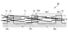
- FIG. 1 is a diagram schematically showing a cross section of a grooved resin molded product 10 (also simply referred to as “resin molded product”) according to the present embodiment.
- the grooved resin molded product 10 contains an inorganic filler 11, and a plurality of fine grooves 12 (also simply referred to as “grooves”) from which the inorganic filler 11 is exposed are formed on the surface 10 a of the grooved resin molded product 10.
- the grooved resin molded product 10 contains an inorganic filler 11, and a plurality of fine grooves 12 (also simply referred to as “grooves”) from which the inorganic filler 11 is exposed are formed on the surface 10 a of the grooved resin molded product 10.
- grooves also simply referred to as “grooves”
- variety in the surface 10a) in the some micro groove 12 formed in the surface 10a the width W of the peak 13 located between the some micro groove 12 13 and the width W 12 of the minute groove 12 (W 13 : W 12 ) are formed so as to be 1: 1.5 to 5.
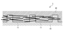
- the composite molded product 1 using the resin molded product 10 has the surface 10a of the resin molded product 10 in which a plurality of microgrooves 12 are formed as a contact surface. It is formed by welding another molded product 20.
- the type of the resin is not particularly limited as long as the fine groove 12 can be formed by a resin removing means such as laser irradiation or chemical treatment.
- a resin removing means such as laser irradiation or chemical treatment.
- PPS polyphenylene sulfide
- LCP liquid crystal polymer
- PBT polybutylene terephthalate
- POM polyacetal
- examples of the chemical treatment include decomposition treatment with acid or alkali, dissolution treatment with a solvent, and the like.
- an amorphous thermoplastic resin it is easy to dissolve in various solvents, but in the case of a crystalline resin, both solvents are selected and used.
- PBT polybutylene terephthalate
- POM polyacetal
- the resin may be thermoplastic or thermosetting.
- the inorganic filler 11 is not particularly limited as long as it is exposed to the minute groove 12 by removing a part of the resin constituting the grooved resin molded product 10 to form the minute groove 12.
- the inorganic filler 11 is exposed from the side wall 12a of the formed microgroove 12 into the space (in the groove) of the microgroove 12, and the grooved resin molded product 10 and the other molded product 20 are combined molded products.
- it plays the role of an anchor that suppresses the separation (see FIG. 2).
- by exposing the inorganic filler 11 to the minute groove 12 in this way it is possible to prevent the inorganic filler 11 itself from dropping from the composite molded article 1.
- the inorganic filler 11 is not particularly limited, and examples thereof include glass fiber, carbon fiber, whisker fiber, glass flake, and mica.
- the length of the inorganic filler 11 is preferably such that the length in the longitudinal direction is longer than the length in the short direction of the microgroove 12 (width direction in the cross-sectional view of FIG. 1).
- the length of the micro grooves 12 in the short direction is preferably shorter than the length of the inorganic filler 11 in the long direction.
- the average fiber length is preferably longer than the length of the micro grooves 12 in the short direction, and if the shape is irregular, plate-like, or particulate, the long diameter, preferably the average particle It is preferable that the diameter is longer than the length of the minute groove 12 in the short direction.
- the inorganic filler 11 exposed in the microgrooves 12 serves as an anchor that suppresses the destruction of the grooved resin molded product 10 and other molded products 20 as described above. Therefore, in order to fulfill this role, for example, the uneven crests 13 formed by removing a part of the resin by the laser irradiated portion and the non-irradiated portion are replaced by the inorganic filler 11 exposed in the minute groove 12. It is preferable to bridge (bridge). And it is preferable that the shape of the inorganic filler 11 is a fibrous form by the point which can be bridge
- the content of the inorganic filler 11 is not particularly limited, but is preferably in the range of 5 to 80 parts by weight with respect to 100 parts by weight of the resin. If the content is less than 5 parts by weight, even if the inorganic filler 11 is exposed in the microgrooves 12, it may not be able to fulfill the role of an anchor that suppresses the breakage of the grooved resin molded product 10 and other molded products 20 There is sex. On the other hand, if the content exceeds 80 parts by weight, the grooved resin molded product 10 may not have sufficient strength.
- Suitable commercially available resin material containing inorganic filler 11 Suitable commercially available resin material containing inorganic filler 11
- a resin material containing the inorganic filler 11 PPS with glass fiber (product name: Durafide PPS 1140A7, manufactured by Polyplastics), PPS with glass fiber / inorganic filler (product name: Durafide PPS 6165A7, poly Plastics), glass fiber LCP (product name: Vectra LCP E130i, manufactured by Polyplastics) and the like are commercially available.
- a plurality of minute grooves 12 are formed on the surface 10a of the resin molded product 10, and the inorganic filler 11 is exposed from the side wall (side surface) 12a.
- the minute groove 12 is formed by removing a part of the resin constituting the resin molded product 10, and the inorganic filler 11 is protruded from the side wall 12 a by removing a part of the resin in this way. Can be exposed.
- the composite molded product 1 is manufactured.
- the inorganic filler 11 is not exposed.
- the inorganic filler 11 is exposed from the microgroove 12 in a mode in which the other molded product 20 is removed from the composite molded product 1. If so, it is assumed that “the inorganic filler 11 is exposed in the minute groove 12”.
- the longitudinal direction of the microgroove 12 (the direction toward the back side in the cross-sectional view of FIG. 1) is preferably different from the longitudinal direction of the inorganic filler 11.
- the longitudinal direction of the groove 12 and the longitudinal direction of the inorganic filler 11 are the same, for example, the uneven portions 13 formed by removing a part of the resin by the laser irradiation site and the non-irradiation site.
- the inorganic filler 11 cannot be suitably placed between them.
- the inorganic filler 11 is likely to drop off from the grooved resin molded product 10, and there is a possibility that the role of an anchor that suppresses the breakage of the grooved resin molded product 10 and other molded products 20 cannot be sufficiently achieved.
- the microgrooves 12 by performing laser irradiation or the like on the resin so that the longitudinal direction of the microgrooves 12 is different from the longitudinal direction of the inorganic filler 11. .
- one resin molded product 50 the minute groove (referred to as “minute groove 51” for convenience) is formed.
- a composite molded product (referred to as “composite molded product 70” for convenience) is manufactured by welding and integrating another molded product (referred to as “other molded product 60” for convenience) on the surface. To do.
- a resin constituting one resin molded product 50 a resin material whose melting point is lower than a melting point of a material such as a resin constituting the other molded product 60, more specifically, a molding temperature of the other molded product 60 is lower. May be used.
- the other molded product 60 when the other molded product 60 is melted and filled (molded) with respect to the one resin molded product 50 with the groove, the one resin molded product 50 is melted at a high molding temperature, The wall of the minute groove 51 formed on the surface may be pushed down and damaged as it falls down. If it becomes like this, even if an inorganic filler is exposed to the micro groove 51, the melt of the material which comprises the other molded article 60 does not fully enter into the micro groove 51, and the anchor effect via an inorganic filler Cannot be obtained sufficiently.
- the microgrooves 12 formed on the grooved resin molded article 10 to control the width W 12 of the fine groove 12 in the surface 10a of the grooved resin molded article 10 in a predetermined range. Specifically, the ratio of the width W 13 of the mountain 13 which is positioned between the plurality of microgrooves 12 and the width W 12 of the fine grooves 12 become 1.5 ⁇ 5: (W 13: W 12) 1 As described above, the groove width of the minute groove 12 is increased.
- the width W 12 and the width W 13 refer to the width on the surface 10a of the grooved resin molded product 10, and the width (groove width) W 12 of the minute groove 12 is as shown by the dotted line X in FIG. It is the opening of the groove 12 and the width of the groove on the extension line (the same surface) of the surface (surface 10a) of the crest 13.
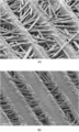
- FIG. 3A shows an electron micrograph of the grooved resin molded product 10 in which the microgrooves 12 are formed on the surface 10a.
- the width of the minute groove 12 (groove width) is increased, and the ratio expressed by W 13 : W 12 is 1: 1.5 to 5 To be.
- the groove width of the micro-groove 12 is thus increased, so that the melting point of the resin is higher than the molding temperature of the other molded product 20 or the melting point of the material constituting the other molded product 20. Even if it is low, sufficient space can be formed to allow the material constituting the other molded article 20 to flow.
- the material constituting the other molded product 20 can be surely poured into the minute groove 12 and exposed from the minute groove 12.
- the anchor effect via the inorganic filler 11 can be exerted, and the other molded product 20 can be firmly adhered (joined).
- each one of the micro grooves 12 and the ridges 13 is set as one set (pitch), and when the one pitch is 200 ⁇ m, for example,
- the pitch formed by the minute grooves 12 and the peaks 13 is used. It can be appropriately determined according to the size of the. However, considering that the anchor effect is suitably obtained, the width of the pitch in which each one of the micro grooves 12 and the peaks 13 is one set is preferably 100 ⁇ m or more and 500 ⁇ m or less, and 200 ⁇ m or more and 300 ⁇ m or less. More preferably. If the width of the pitch is too narrow, the inorganic filler 11 is not exposed from the side surface of the microgroove 12, and the anchor effect by the inorganic filler 11 may not be suitably obtained.
- the inorganic filler 11 is likely to drop off from the grooved resin molded product 10, and the inorganic filler 11 sufficiently serves as an anchor that suppresses the destruction of the grooved resin molded product 10 and other molded products 20. May not be able to fulfill.
- the width W 12 of the fine groove 12 in the surface 10a of the grooved resin molded product 10 is less than 1.5 times, other molded article 20
- the grooved resin molded product 10 is melted, and the wall of the minute groove 12 formed in the resin molded product 10 falls down, resulting in damage.
- the width W 12 of the microgroove 12 exceeds 5 times the width W 13 of the peak 13, the role of the anchor by the inorganic filler 11 is not sufficiently fulfilled, and external force is applied to the composite molded product 1. There is a possibility that the other molded article 20 is destroyed.
- width W 12 of the microgrooves 12 1 at a ratio represented by "W 13 W 12": 2 be provided with 1-4 and the fine grooves 12 so that the width W12 made more preferred.
- W 13 W 12 2
- the minute groove 12 may be formed in a stripe shape as shown in FIG. 3 (A) on the surface 10a of the resin molded product 10, and as shown in FIG. 3 (B), the minute groove 12 may be formed. 12 may be formed in a lattice shape.
- the longitudinal direction of the microgrooves 12 can be formed in an oblique lattice shape different from the longitudinal direction of the inorganic filler 11.
- the melt of the material constituting the other molded product 20 can be poured into the micro grooves 12 more reliably.
- the width W 13 of width W 12 and mountain 13 of the fine groove 12 at the surface 10a, one of the longitudinal microgrooves 12 to form a grating shape (e.g. in Fig. 3
- the depth D of the microgroove 12 is preferably not less than 1 ⁇ 2 of the length in the short direction of the microgroove 12 (that is, the width W12 of the microgroove 12 ).
- the inorganic filler 11 exposed to the microgroove 12 is formed when the composite molded article 1 is formed by joining with another molded article 20.
- a sufficient anchor effect does not occur between the other molded products 20 and the grooved resin molded product 10 and the other molded products 20 cannot be firmly brought into close contact with each other.
- the resin is partially removed by performing laser irradiation, chemical treatment, or the like on the resin molded product containing the inorganic filler 11, and a plurality of minute grooves 12 are formed on the surface 10 a of the resin molded product. Obtained by forming.
- the surface 10 a of the resin molded product is partially removed in this way to form the microgroove 12, so that the inorganic filler 11 contained in the resin molded product becomes the microgroove 12. It is exposed from the side wall 12a.
- the laser irradiation is set based on the type of material to be irradiated, the output of the laser device, and the like. However, if the resin is not irradiated with appropriate energy to form the microgrooves 12, the inorganic filler 11 is sufficiently exposed. Otherwise, it becomes difficult to form the micro-groove 12 having the width W 12 and the depth D as set.
- the width W 12 at the surface 10a of the grooved resin molded product 10 when forming the microgrooves 12, the width W 12 at the surface 10a of the grooved resin molded product 10, the width W 13 and its microgrooves mountain 13 which is positioned between the plurality of microgrooves 12
- the ratio of 12 to the width W 12 (W 13 : W 12 ) is set to 1: 1.5 to 5.
- the melting point of the resin constituting the resin molded product 10 is higher than the molding temperature or the melting point of the other molded product 20. Even if the temperature is low, the resin constituting the other molded product 20 can be poured into the minute groove 12 before the minute groove 12 of the resin molded product 10 is melted and filled. Thereby, the anchor effect by the inorganic filler 11 can be produced effectively, and the other molded product 20 can be sufficiently bonded to the resin molded product 10.
- the glass fiber or the like as the inorganic filler 11 partially shields the energy of the laser. Therefore, in order to remove the resin deeply, if laser irradiation is performed a plurality of times, it is necessary to give higher energy by the amount of energy absorbed when the laser hits an already exposed glass fiber or the like later. Therefore, when laser irradiation is repeated a plurality of times, it is preferable to include a step of increasing the laser irradiation amount from the previous irradiation amount.
- an acid, an alkali, an organic solvent, or the like corresponding to the characteristics of the resin is selected and used.
- the groove can be formed by decomposing and removing the location where the minute groove is provided with an acid.
- the groove can be formed by previously removing a portion other than the location where the minute groove is provided on the surface of the molded product and then dissolving and removing the organic solvent.
- FIG. 2 is a schematic diagram of an enlarged cross section of the composite molded article 1 according to the present embodiment. As shown in FIG. 2, in the composite molded product 1, the surface (surface 10 a) having the minute grooves 12 of the grooved resin molded product 10 is used as a contact surface, and another molded product 20 is disposed adjacent to the surface. ing.
- the form of the other molded product 20 inside the minute groove 12 is not particularly limited, but in order to obtain a high anchor effect, the other molded product 20 contains the inorganic filler 11 inside the minute groove 12. It is preferable to arrange so as to surround.
- the other molded product 20 is not particularly limited as long as it can enter the minute groove 12 of the resin molded product 10 where the inorganic filler 11 is exposed in an uncured state.
- curable resin thermosetting resin, photocurable resin, radiation curable resin, etc.
- thermoplastic resin etc.
- the molding temperature of the other molded product 20, that is, the melt of the material constituting the other molded product 20 is poured into the surface 10 a of the grooved resin molded product 10 where the microgrooves 12 are formed. Even when the temperature is higher than the melting point of the resin constituting the grooved resin molded product 10 (or when the melting point of the other molded product 20 is higher than the melting point of the resin molded product 10), the grooved resin molded product 10 The melt can be surely poured into the microgrooves 12 formed in the above.
- a sufficient space for allowing the material constituting the other molded product 20 to flow into the minute groove 12 before the minute groove 12 is melted and buried. Can be formed. Thereby, the anchor effect through the inorganic filler 11 exposed from the microgroove 12 can be exhibited effectively, and the other molded product 20 can be effectively joined.
- the molding is performed more than the melting point of the PPS.
- PPS polyphenylene sulfide
- fusing point can be mentioned.
- the composite molded product 1 has the surface (surface 10a) having the minute grooves 12 of the resin molded product 10 with grooves as a contact surface, and another molded product 20 is disposed adjacent to the surface.
- This composite molded product 1 can be obtained by, for example, multiple molding (insert molding).
- FIG. 4 is a schematic diagram for explaining a method of obtaining the composite molded article 1 by multiple molding.
- the primary resin is primary molded to produce a preliminary body 10 ′ of the grooved resin molded product 10 (FIG. 4 (1)).
- the resin is partially removed from a part of the surface 10a ′ of the preliminary body 10 ′, and a plurality of microgrooves 12 are formed on the surface 10a ′ (FIG. 4B).
- channel is produced.
- the width W 12 of a plurality of microgrooves 12 are formed, the width W 13 of the mountain 13 which become located between the microgrooves 12 width W of the fine grooves 12
- the microgrooves 12 are formed so that the ratio (W 13 : W 12 ) to 12 is 1: 1.5 to 5.
- the grooved resin molded product 10 is put into a mold (not shown), and a surface 10 a having a minute groove 12 is used as a contact surface inside the mold.
- the next resin (uncured material (melt)) of the material constituting the other molded product 20 is poured and inserted (injection injection), and this is cured.
- the flow direction of the secondary resin (melt) with respect to the surface 10a of the grooved resin molded product is not particularly limited, but the longitudinal direction of the microgrooves 12 formed in the grooved resin molded product 10 is not limited. It is preferable that the liquid is poured so as to be parallel to the flow. If the secondary resin is caused to flow in a direction orthogonal to the longitudinal direction of the microgrooves 12, the walls of the microgrooves 12 are liable to fall due to the flow of the secondary resin, and the possibility that the grooves are filled increases. On the other hand, by flowing the secondary resin so as to be parallel to the longitudinal direction of the microgrooves 12, it is possible to suppress the microgrooves 12 from being melted and damaged, and more effectively A secondary resin can be poured into the groove 12.
- the composite molded product 1 with curable resin (other molded products 20) can be obtained by multiple molding.
- a thermoplastic resin obtained by heating and melting the secondary resin a composite molded product 1 with a thermoplastic resin by multiple molding can be obtained.
- a plurality of fine grooves were formed on the surface of the resin molded product by laser irradiation under the conditions shown in Table 1 below.
- the depth of the minute groove was 100 ⁇ m.
- pitch refers to a value obtained by combining the width of the groove portion of the minute groove on the surface of the resin molded product and the width of the peak portion on one side adjacent to the groove portion.
- W 13 : W 12 is the ratio of the width of the ridge (projection) to the groove (depression) when the width W 12 of the groove of the minute groove and the width W 13 of the ridge.
- the “shape of minute groove on the surface” is the shape of the minute groove on the surface of the resin molded product, which is “horizontal stripe” as shown in FIG. 3 (A) or shown in FIG. 3 (B). It shows that it is such “slanted lattice”.
- the conditions for the laser irradiation treatment were as follows. (Conditions for laser irradiation in micro-groove formation) Oscillation wavelength: 1.064 ⁇ m Maximum rated output: 13W (average) Laser output: 45% Scanning speed: 1000mm / sec Frequency: 40kHz Overwriting: 40 times * Depicted 3 times at 30 ⁇ m pitch * Preheating at 230 ° C x 3 hr
- Example 2 in the production of a grooved resin molded product, a grooved resin molded product was produced in the same manner as in Example 1 except that the shape of the minute grooves on the surface of the resin molded product was an oblique lattice shape, A composite molded product was produced based on the obtained grooved resin molded product.
- Example 4 in the production of a grooved resin molded product, a grooved resin molded product was produced in the same manner as in Example 3 except that the shape of the minute grooves on the surface of the resin molded product was an oblique lattice shape, A composite molded product was produced based on the obtained grooved resin molded product.
- FIG. 5A is a SEM photograph of the grooved resin molded product produced in Example 1.
- FIG. 5B is a SEM photograph of the grooved resin molded product produced in Comparative Example 1. The magnification was 200 times.
- FIG. 7A is a cross-sectional photograph of the composite molded product of Example 1.
- FIG. 7B is a cross-sectional photograph of the composite molded product of Comparative Example 1.
- the lower layer is a PPS which is a grooved resin molded product
- the upper layer is an LCP which is a secondary molded product.
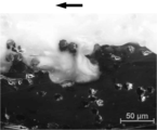
- FIG. 8 shows another cross-sectional photograph of the composite molded article according to Comparative Example 1 using an optical microscope.
- the grooved resin As can be seen from the cross-sectional photograph of FIG. 8, in the composite molded product according to Comparative Example 1, with the flow of the LCP as the secondary molded product (along the flow direction indicated by the arrow in the figure), the grooved resin It can be seen that the wall of the minute groove formed on the surface of the molded product melts and falls down, and the minute groove is closed. It can also be seen that PPS and LCP are mixed with each other as the minute groove melts. In this case, as shown in FIG. 7B, a sufficient amount of LCP does not enter the minute groove.
- Example 2 and Example 4 in which the microgrooves were formed in a slanted lattice shape it was found that in all the samples, the fracture mode was not the delamination fracture but the base metal fracture, and higher bonding strength was obtained.
- the shape of the minute groove is a stripe shape or a lattice shape.
- the breaking load was about 30 to 40 N, and the bonding strength was very low. This is because, as shown in FIG. 7B and FIG. 8, the molding temperature when pouring the LCP as the secondary molded product is higher than the melting point of PPS. This is considered to be caused by melting and breakage, and no room for LCP to enter. Thereby, it is thought that the anchor effect by glass fiber was not fully exhibited but became low joint strength.
Landscapes
- Engineering & Computer Science (AREA)
- Mechanical Engineering (AREA)
- Health & Medical Sciences (AREA)
- Toxicology (AREA)
- Manufacturing & Machinery (AREA)
- Injection Moulding Of Plastics Or The Like (AREA)
- Treatments Of Macromolecular Shaped Articles (AREA)
- Lining Or Joining Of Plastics Or The Like (AREA)
- Shaping Of Tube Ends By Bending Or Straightening (AREA)
- Compositions Of Macromolecular Compounds (AREA)
Abstract
例えば一の成形品(樹脂成形品)の樹脂の融点が他の成形品の成形温度よりも低い場合であっても、その一方の樹脂成形品と他の成形品とを十分に接合させることができるようにする。 本発明に係る溝付き樹脂成形品は、無機充填剤11を含有し、その無機充填剤11が露出された微小溝12が当該樹脂成形品の表面10aに複数、微小溝12の間に位置する山13と微小溝12との表面10aにおける幅が1:1.5~5の比率(W13:W12)で形成されてなる。そして、複合成形品1は、このような溝付き樹脂成形品の表面10aを接触面として、他の成形品20が隣接して配置されてなる。
Description
本発明は、溝付き樹脂成形品、その溝付き樹脂成形品を用いた複合成形品、並びにその複合成形品の製造方法に関する。
近年、自動車、電気製品、産業機器等をはじめとした分野では、二酸化炭素の排出量削減、製造コストの削減等の要請に応えるため、金属成形品の一部を樹脂成形品に置き換える動きが広がっている。これに伴い、樹脂成形品と金属成形品とを一体化した複合成形品が広く普及している。また、これに限らず、同種又は異種の材料からなる成形品を一体化した複合成形品も広く普及している。
一の成形品と他の成形品とを一体化した複合成形品の製造方法としては、例えば、次のようなものが提案されている。すなわち、特許文献1には、一方の成形品を構成する樹脂にガラスファイバー等の充填剤を混入して成形し、他方の成形品を構成する樹脂を接着する面に薬品、プラズマ、炎等の処理を施して厚さ0.数μm~数10μmの樹脂を除去した後、その他方の樹脂を接着する面に他方の樹脂を接して充填、成形して、接着させる方法が提案されている。また、特許文献2には、一方の樹脂成形品の表面に電磁放射線を照射することで、表面にナノ構造を形成し、その後、その表面に他方の樹脂成形品を接して充填、成形して、一体化させる方法が提案されている。
また、無機充填剤を含有した樹脂成形品(1次樹脂成形品)の表面に微小溝を形成して無機充填剤を露出させ、その微小溝内に2次成形品を構成する材料を流し入れることで一体化させて、強度を向上させた複合成形品を製造する方法も研究されている。
しかしながら、一の成形品と他の成形品とを接合したときの強度に関してさらなる改良の余地がある。また、例えば、上述したように一の成形品の表面に微小溝を形成させた場合でも、その一の成形品を構成する樹脂の融点が他の成形品を構成する材料の成形温度又は融点よりも低い場合においては、一の成形品の表面に他の成形品の材料(溶融物)を流し込む際に微小溝が溶融して破損してしまい、その微小溝に他の成形品の溶融物が十分に入り込まず、高い強度で接合することができないことがある。
本発明は、上述した状況に鑑みてなされたものであり、例えば一の成形品(樹脂成形品)の樹脂の融点が他の成形品の成形温度又は融点よりも低い場合でも、その一方の樹脂成形品と他の成形品とを十分に接合させることができるようにすることを目的とする。
本発明者らは、上述した課題を解決するために鋭意検討を重ねた。その結果、一方の樹脂成形品について、無機充填剤を含有する樹脂成形品の樹脂を一部除去して、無機充填剤が露出される微小溝を、樹脂成形品の表面に複数、かつ、その溝幅を広くとるように形成することを見出した。これにより、その溝付き樹脂成形品(一の成形品)を構成する樹脂の融点が、他の成形品を構成する材料の成形温度又は融点よりも低い場合であっても、その微小溝に他の成形品の材料の溶融物を十分に有効に流し入れて、無機充填剤によるアンカー効果を効果的に発揮させることができることを見出し、本発明を完成するに至った。すなわち、本発明は以下のものを提供する。
(1)本発明は、無機充填剤を含有し、該無機充填剤が露出された微小溝が当該樹脂成形品の表面に複数、該微小溝の間に位置する山部と該微小溝との前記表面における幅が1:1.5~5の比率で形成されてなる溝付き樹脂成形品である。
(2)また本発明は、(1)の発明において、前記無機充填剤が前記微小溝の側壁から突出して露出される溝付き樹脂成形品である。
(3)また本発明は、(1)又は(2)の発明において、前記表面において前記微小溝が格子状に形成されてなる溝付き樹脂成形品である。
(4)また本発明は、(1)乃至(3)のいずれかの発明において、前記無機充填剤は繊維状無機充填剤である溝付き樹脂成形品である。
(5)また本発明は、(1)乃至(4)のいずれかの発明において、前記溝はレーザ照射によって形成される溝付き樹脂成形品である。
(6)また本発明は、(1)乃至(5)のいずれかの発明において、前記微小溝を有する表面上に、当該溝付き樹脂成形品を構成する樹脂の融点よりも高い成形温度の材料からなる他の成形品を隣接して配置して複合成形品とするためのものである溝付き樹脂成形品である。
(7)また本発明は、複合成形品であって、(1)乃至(6)のいずれかの発明に係る溝付き樹脂成形品の前記表面上に、該溝付き樹脂成形品を構成する樹脂よりも融点が高い材料からなる他の成形品が隣接して配置されてなる複合成形品である。
(8)また本発明は、無機充填剤を含有する第1の樹脂成形品の表面上に、該第1の樹脂成形品を構成する樹脂の融点よりも高い成形温度からなる第2の成形品を隣接して配置して複合成形品とする複合成形品の製造方法であって、前記第1の樹脂成形品の前記第2の成形品が隣接する表面に、その側壁から前記無機充填剤が突出する微小溝を複数、該微小溝の間に位置する山部と該微小溝の溝部との該表面における幅が1:1.5~5の比率となるように形成する溝形成工程と、前記微小溝が形成された前記第1の樹脂成形品の表面上に、前記第2の成形品を構成する材料の溶融物を流し込んで固化させて成形する成形工程とを有する複合成形品の製造方法である。
(9)また本発明は、(8)の発明において、前記成形工程が前記微小溝を有する面を接触面として前記第2の成形品を構成する材料を流し込んで射出成形により固化させて成形する工程である複合成形品の製造方法である。
本発明によれば、例えば一の成形品(樹脂成形品)の樹脂の融点が他の成形品の成形温度又は融点よりも低い場合であっても、その一方の樹脂成形品と他の成形品とを十分に接合させることができる。
以下、本発明の具体的な実施形態(以下、「本実施の形態」という)について、図面を参照しながら詳細に説明する。なお、本発明は、以下の実施の形態に限定されるものではなく、本発明の要旨を変更しない範囲で種々の変更が可能である。
<1.溝付き樹脂成形品>
図1は、本実施の形態に係る溝付き樹脂成形品10(単に「樹脂成形品」ともいう)の断面を模式的に示した図である。溝付き樹脂成形品10は、無機充填剤11を含有し、その無機充填剤11が露出された微小溝12(単に「溝」ともいう)が当該溝付き樹脂成形品10の表面10aに複数形成されている。
図1は、本実施の形態に係る溝付き樹脂成形品10(単に「樹脂成形品」ともいう)の断面を模式的に示した図である。溝付き樹脂成形品10は、無機充填剤11を含有し、その無機充填剤11が露出された微小溝12(単に「溝」ともいう)が当該溝付き樹脂成形品10の表面10aに複数形成されている。
そして、この溝付き樹脂成形品10では、その表面10aに形成された複数の微小溝12における幅W12(表面10aにおける幅)に関して、複数の微小溝12の間に位置する山13の幅W13とその微小溝12の幅W12との比率(W13:W12)が1:1.5~5となるように形成されてなることを特徴としている。
なお、詳しくは後述するが、図2に示すように、この樹脂成形品10を用いた複合成形品1は、複数の微小溝12が形成された樹脂成形品10の表面10aを接触面として、他の成形品20を溶着することで形成される。
(樹脂)
樹脂の種類としては、レーザ照射又は化学処理等の樹脂除去手段により微小溝12を形成できるものであれば特に限定されない。例えば、レーザ照射により溝を形成できるものとして、ポリフェニレンスルフィド(PPS)、液晶ポリマー(LCP)、ポリブチレンテレフタレート(PBT)、ポリアセタール(POM)等を挙げることができる。
樹脂の種類としては、レーザ照射又は化学処理等の樹脂除去手段により微小溝12を形成できるものであれば特に限定されない。例えば、レーザ照射により溝を形成できるものとして、ポリフェニレンスルフィド(PPS)、液晶ポリマー(LCP)、ポリブチレンテレフタレート(PBT)、ポリアセタール(POM)等を挙げることができる。
また、化学処理としては、酸又はアルカリによる分解処理や、溶剤による溶解処理等が挙げられる。非結晶性熱可塑性樹脂の場合は、様々な溶剤に溶解しやすいが、結晶性樹脂の場合は、両溶媒を選択して使用する。例えば、酸又はアルカリを加えることによって溝を形成できるものとして、ポリブチレンテレフタレート(PBT)、ポリアセタール(POM)等を挙げることができる。ここで、化学処理においては、溝を形成する部位に限定した化学処理を行い、そして化学処理による生成物を除去することが重要となる。
なお、樹脂としては、熱可塑性であってもよいし、熱硬化性であってもよい。
(無機充填剤)
無機充填剤11は、溝付き樹脂成形品10を構成する樹脂の一部を除去して微小溝12を形成することで、その微小溝12に露出するものであれば特に限定されない。この無機充填剤11は、形成された微小溝12の側壁12aから微小溝12の空間内(溝内)に露出して、この溝付き樹脂成形品10と他の成形品20とで複合成形品1とする際に、それらの分離を抑制するアンカーの役割を果たす(図2参照)。また、このように無機充填剤11を微小溝12に露出させることで、無機充填剤11そのものが複合成形品1から脱落することを防ぐことができる。
無機充填剤11は、溝付き樹脂成形品10を構成する樹脂の一部を除去して微小溝12を形成することで、その微小溝12に露出するものであれば特に限定されない。この無機充填剤11は、形成された微小溝12の側壁12aから微小溝12の空間内(溝内)に露出して、この溝付き樹脂成形品10と他の成形品20とで複合成形品1とする際に、それらの分離を抑制するアンカーの役割を果たす(図2参照)。また、このように無機充填剤11を微小溝12に露出させることで、無機充填剤11そのものが複合成形品1から脱落することを防ぐことができる。
無機充填剤11としては、特に限定されないが、ガラス繊維、炭素繊維、ウィスカー繊維、ガラスフレーク、マイカ等を挙げることができる。
また、無機充填剤11の長さは、その長手方向の長さが微小溝12の短手方向(図1の断面図における幅方向)の長さよりも長いことが好ましい。言い換えると、微小溝12の短手方向の長さは、無機充填剤11の長手方向の長さよりも短いことが好ましい。例えば、形状が繊維状であれば、平均繊維長が微小溝12の短手方向の長さよりも長いことが好ましく、形状が不定形、板状、粒子状であれば、長径、好ましくは平均粒子径が微小溝12の短手方向の長さよりも長いことが好ましい。
本実施の形態においては、微小溝12で露出する無機充填剤11は、上述したように、溝付き樹脂成形品10及び他の成形品20の破壊を抑えるアンカーの役割を果たすものである。したがって、その役割を果たすにあたって、例えばレーザ照射部位と非照射部位とにより樹脂の一部が除去されることで形成される凹凸の山13同士を、その微小溝12に露出した無機充填剤11によって架ける(ブリッジする)ようにすることが好ましい。そして、このように無機充填剤11によって架けることができるようにする点で、その無機充填剤11の形状は繊維状であることが好ましい。なお、樹脂に形成される凹凸において、その凹部が微小溝12であり、複数の微小溝12に挟まれた凸部が山13となる。
無機充填剤11の含有量は、特に限定されないが、樹脂100重量部に対して5重量部以上80重量部以下の範囲であることが好ましい。含有量が5重量部未満であると、無機充填剤11が微小溝12で露出したとしても、溝付き樹脂成形品10及び他の成形品20の破壊を抑えるアンカーの役割を十分に果たせない可能性がある。一方で、含有量が80重量部を超えると、溝付き樹脂成形品10が十分な強度を有するものとはならない可能性がある。
(無機充填剤11を含有する樹脂材料の好適な市販品)
なお、無機充填剤11を含有する樹脂材料として、ガラス繊維入りPPS(製品名:ジュラファイドPPS 1140A7,ポリプラスチックス社製)、ガラス繊維・無機フィラー入りPPS(製品名:ジュラファイドPPS 6165A7,ポリプラスチックス社製)、ガラス繊維入りLCP(製品名:ベクトラLCP E130i、ポリプラスチックス社製)等が市販されている。
なお、無機充填剤11を含有する樹脂材料として、ガラス繊維入りPPS(製品名:ジュラファイドPPS 1140A7,ポリプラスチックス社製)、ガラス繊維・無機フィラー入りPPS(製品名:ジュラファイドPPS 6165A7,ポリプラスチックス社製)、ガラス繊維入りLCP(製品名:ベクトラLCP E130i、ポリプラスチックス社製)等が市販されている。
(微小溝)
微小溝12は、樹脂成形品10の表面10aに複数形成されたものであり、その側壁(側面)12aから無機充填剤11が露出されている。この微小溝12は、樹脂成形品10を構成する樹脂の一部を除去することによって形成され、このように樹脂の一部を除去することによって、無機充填剤11をその側壁12aから突出した状態で露出させることができる。
微小溝12は、樹脂成形品10の表面10aに複数形成されたものであり、その側壁(側面)12aから無機充填剤11が露出されている。この微小溝12は、樹脂成形品10を構成する樹脂の一部を除去することによって形成され、このように樹脂の一部を除去することによって、無機充填剤11をその側壁12aから突出した状態で露出させることができる。
なお、図2に示すように、この溝付き樹脂成形品10の微小溝12を有する面(表面10a)を接触面として他の成形品20と一体化させて複合成形品1を製造するところ、この複合成形品1においては無機充填剤11が露出されていない。本明細書では、複合成形品1において無機充填剤11が露出していない場合であっても、複合成形品1から他の成形品20を取り除いた態様において微小溝12から無機充填剤11が露出していれば、「微小溝12において無機充填剤11が露出されている」ものとする。
微小溝12の長手方向(図1の断面図における奥側に向かう方向)は、無機充填剤11の長手方向とは異なることが好ましい。溝12の長手方向と無機充填剤11の長手方向とが同じであると、例えばレーザの照射部位と非照射部位とによって樹脂の一部が除去されることで形成される凹凸の山13同士の間に無機充填剤11を好適に架けることができない可能性がある。すると、無機充填剤11が溝付き樹脂成形品10から脱落しやすくなり、溝付き樹脂成形品10及び他の成形品20の破壊を抑えるアンカーの役割を十分に果たすことができない可能性がある。したがって、図1の断面図に示されるように、微小溝12の長手方向が無機充填剤11の長手方向と異なるように樹脂に対してレーザ照射等を行って微小溝12を形成することが好ましい。
ところで、微小溝が形成された溝付きの一の樹脂成形品(説明便宜上「一の樹脂成形品50」とする)においては、その微小溝(説明便宜上「微小溝51」とする)が形成された面に対して、他の成形品(説明便宜上「他の成形品60」とする)を溶着させて一体化することで、複合成形品(説明便宜上「複合成形品70」とする)を製造する。このとき、一の樹脂成形品50を構成する樹脂として、その融点が、他の成形品60を構成する樹脂等の材料の融点、より詳しくはその他の成形品60の成形温度よりも低い樹脂材料を用いる場合がある。このような場合、溝付きの一の樹脂成形品50に対して他の成形品60を溶かして充填(成形)する際に、その一の樹脂成形品50が高い成形温度により溶融してしまい、その表面に形成された微小溝51の壁が倒れるようにして押し流されて破損してしまうことがある。このようになると、その微小溝51に無機充填剤を露出させても、その微小溝51に他の成形品60を構成する材料の溶融物が十分に入らず、無機充填剤を介したアンカー効果が十分に得られなくなる。
そこで、本実施の形態では、溝付き樹脂成形品10に形成する微小溝12において、溝付き樹脂成形品10の表面10aにおける微小溝12の幅W12を所定の範囲に制御する。具体的には、複数の微小溝12の間に位置する山13の幅W13とその微小溝12の幅W12との比率(W13:W12)が1:1.5~5となるように、微小溝12の溝幅を広くとるようにする。
ここで、幅W12、幅W13は、溝付き樹脂成形品10の表面10aにおける幅をいい、微小溝12の幅(溝幅)W12は、図1の点線Xで示すように、当該溝12の開口部であって、山13の表面(表面10a)の延長線(面一)上における溝部の幅をいう。
図3(A)に、その表面10aに微小溝12を形成させた溝付き樹脂成形品10の電子顕微鏡写真を示す。この図3(A)に示すように、溝付き樹脂成形品10では、微小溝12の幅(溝幅)を広くとり、W13:W12で表される比率で1:1.5~5となるようする。溝付き樹脂成形品10では、このように微小溝12の溝幅を広くとることで、その樹脂の融点が他の成形品20の成形温度又は他の成形品20を構成する材料の融点よりも低い場合であっても、他の成形品20を構成する材料を流し込ませるのに十分な空間を形成することができる。これにより、樹脂成形品10の微小溝12が溶融して埋まってしまう前に、他の成形品20を構成する材料をその微小溝12に確実に流し込ませることができ、微小溝12から露出させた無機充填剤11を介したアンカー効果を発揮させて、他の成形品20を強固に密接(接合)させることができる。
具体例を挙げると、樹脂成形品10の表面10aにおいて、微小溝12と山13とのそれぞれ1つずつを1セット(ピッチ)とし、その1ピッチが200μmであったとき、例えば、山13の幅W13を80μmとし、微小溝12の幅W12を120μmとすることができる(なお、この場合、W13:W12=1:1.5となる。)。また、200μmのピッチにおいて、例えば、山13の幅W13を33.3μmとし、微小溝12の幅W12を166.7μmとすることができる(なお、この場合、およそW13:W12=1:5となる。)。
また、微小溝12と山13との1ピッチが300μmであったときには、例えば、山13の幅W13を120μmとし、微小溝12の幅W12を180μmとすることができる(なお、この場合、W13:W12=1:1.5となる。)。また、300μmのピッチにおいて、山13の幅W13を50μmとし、微小溝12の幅W12を250μmとすることができる(なお、この場合、W13:W12=1:5となる。)。
なお、これらの具体例は、あくまでも例示であってこれに限られるものではなく、W13:W12=1:1.5~5の範囲であれば、微小溝12と山13とからなるピッチの大きさに応じて適宜決定することができる。しかしながら、アンカー効果を好適に得ることを考慮すると、微小溝12と山13とのそれぞれ1つずつを1セットとするピッチの幅は、100μm以上500μ以下であることが好ましく、200μm以上300μm以下であることがより好ましい。ピッチの幅が狭すぎると、無機充填剤11が微小溝12の側面から露出されず、無機充填剤11によるアンカー効果を好適に得られない可能性がある。ピッチの幅が広すぎると、無機充填剤11が溝付き樹脂成形品10から脱落しやすく、無機充填剤11が溝付き樹脂成形品10及び他の成形品20の破壊を抑えるアンカーの役割を十分に果たすことができない可能性がある。
溝付き樹脂成形品10の表面10aにおける微小溝12の幅W12に関して、山13の幅W13に対して微小溝12の幅W12が1.5倍未満であると、他の成形品20の溶着時に溝付き樹脂成形品10が溶融し、その樹脂成形品10に形成させた微小溝12の壁が倒れて破損が生じる。一方で、山13の幅W13に対して微小溝12の幅W12が5倍を超えると、無機充填剤11によるアンカーの役割が十分に果たされず、複合成形品1に外力が加わることで他の成形品20が破壊する可能性がある。
また、微小溝12の幅W12に関しては、「W13:W12」で表される比率で1:2~4となる幅W12となるように微小溝12を設けることが、より好ましい。これにより、より効果的に、溝付き樹脂成形品10の微小溝12への他の成形品20を構成する溶融物の流し込みを可能にし、アンカー効果を一層に高めて接合強度の高い樹脂成形品10とすることができる。
ここで、微小溝12は、樹脂成形品10の表面10aにおいて、図3(A)に示したような縞状に形成されてもよく、また、図3(B)に示すように、微小溝12が交差する格子状に形成されてもよい。微小溝12を格子状に形成する場合には、微小溝12の長手方向が無機充填剤11の長手方向とは異なる斜格子状に形成することもできる。図3(B)に示すように、微小溝12を格子状に形成することで、より確実に他の成形品20を構成する材料の溶融物を微小溝12に流し込ませることができる。
微小溝12を格子状に形成する場合、その表面10aにおける微小溝12の幅W12と山13の幅W13については、格子形状を形成する微小溝12の一方の長手方向(例えば図3中のx軸方向)を見たときに、その微小溝12と山13の幅がW13:W12=1:1.5~5の関係を満たしていればよい。また、微小溝12の他方の長手方向(例えば図3中のy軸方向)を見たときに、その微小溝12と山13の幅がW13:W12=1:1.5~5の関係を満たしていればよい。
なお、このように微小溝12を格子状としたときに、微小溝12の一方の長手方向(x軸)及び他方の長手方向(y軸)における微小溝12と山13の幅の比率は、それぞれがW13:W12=1:1.5~5の関係を満たしていれば、同じ比率であっても、異なる比率であってもよい。
微小溝12の深さDは、その微小溝12の短手方向の長さ(すなわち微小溝12の幅W12)の1/2以上であることが好ましい。深さDが微小溝12の幅W12の1/2未満であると、他の成形品20と接合させて複合成形品1を形成する際に、微小溝12に露出する無機充填剤11と他の成形品20との間に十分なアンカー効果が生じず、溝付き樹脂成形品10と他の成形品20とを強固に密接させることができない可能性がある。
<2.溝付き樹脂成形品の製造方法>
溝付き樹脂成形品10は、無機充填剤11を含有する樹脂成形品にレーザ照射や化学処理等を行って樹脂を部分的に除去し、その樹脂成形品の表面10aに複数の微小溝12を形成することによって得られる。溝付き樹脂成形品10では、このようにして樹脂成形品の表面10aを部分的に除去して微小溝12を形成することで、樹脂成形品内に含まれる無機充填剤11が微小溝12の側壁12aから露出される。
溝付き樹脂成形品10は、無機充填剤11を含有する樹脂成形品にレーザ照射や化学処理等を行って樹脂を部分的に除去し、その樹脂成形品の表面10aに複数の微小溝12を形成することによって得られる。溝付き樹脂成形品10では、このようにして樹脂成形品の表面10aを部分的に除去して微小溝12を形成することで、樹脂成形品内に含まれる無機充填剤11が微小溝12の側壁12aから露出される。
レーザの照射は、照射対象材料の種類やレーザ装置の出力等をもとに設定されるが、樹脂に適度のエネルギーを照射して微小溝12を形成しないと、無機充填剤11が十分に露出しなかったり、設定通りの幅W12や深さDの微小溝12を形成することが困難になるため、複数回に分けて行うことが好ましい。
本実施の形態においては、その微小溝12の形成に際して、溝付き樹脂成形品10の表面10aにおける幅W12が、複数の微小溝12の間に位置する山13の幅W13とその微小溝12の幅W12との比率(W13:W12)で1:1.5~5となるようする。
本実施の形態においては、このようにして幅W12を広くした微小溝12を形成することで、その樹脂成形品10を構成する樹脂の融点が他の成形品20の成形温度又は融点よりも低い場合であっても、その樹脂成形品10の微小溝12が溶融して埋まってしまう前に、他の成形品20を構成する樹脂をその微小溝12に流し込むことが可能となる。これにより、無機充填剤11によるアンカー効果を効果的に生じさせることができ、樹脂成形品10に対して他の成形品20を十分に接合させることができる。
ここで、レーザ照射により微小溝12を形成するに際して、無機充填剤11としてのガラス繊維等は、レーザのエネルギーを部分的に遮蔽する。そのため、深くまで樹脂を除去するために、レーザの照射を複数回行おうとすると、後になるほど、レーザが既に露出したガラス繊維等に当たることよって吸収されるエネルギーの分だけ高いエネルギーを与える必要がある。そのため、レーザの照射を複数回繰り返す場合、レーザの照射量を前回の照射量より高める工程を含むことが好ましい。
また、レーザ光透過性の低い無機充填剤11の背面に位置する樹脂を除去するためには、レーザの照射を、樹脂成形品10の表面10aに対して垂直以外の方向から行うことが好ましい。
一方で、化学処理による微小溝12の形成においては、樹脂の特性に応じた酸、アルカリ、有機溶剤等を選択して用いる。酸により樹脂が分解するポリアセタール樹脂成形品では、微小溝を設ける場所を酸で分解除去することで溝を形成することができる。また、有機溶剤に溶けやすい非結晶性樹脂成形品では、予め成形品の表面に微小溝を設ける場所以外をマスキングした後、有機溶剤で溶解除去することで溝を形成することができる。
<3.複合成形品>
図2は、本実施の形態に係る複合成形品1の拡大断面の模式図である。図2に示すように、複合成形品1では、溝付き樹脂成形品10の微小溝12を有する面(表面10a)を接触面として、その面上に他の成形品20が隣接して配置されている。
図2は、本実施の形態に係る複合成形品1の拡大断面の模式図である。図2に示すように、複合成形品1では、溝付き樹脂成形品10の微小溝12を有する面(表面10a)を接触面として、その面上に他の成形品20が隣接して配置されている。
微小溝12の内部における他の成形品20の態様としては、特に限定されるものでないが、高いアンカー効果を得るために、微小溝12の内部において、他の成形品20が無機充填剤11を囲むように配置されることが好ましい。
(他の成形品)
ここで、他の成形品20としては、未硬化状態の場合に、無機充填剤11が露出された樹脂成形品10の微小溝12に入ることが可能なものであれば特に限定されるものではなく、例えば、硬化性樹脂(熱硬化性樹脂、光硬化性樹脂、放射線硬化性樹脂等)、熱可塑性樹脂等を挙げることができる。また、上述したような樹脂に限られず、ゴム、接着剤、金属等であってもよい。
ここで、他の成形品20としては、未硬化状態の場合に、無機充填剤11が露出された樹脂成形品10の微小溝12に入ることが可能なものであれば特に限定されるものではなく、例えば、硬化性樹脂(熱硬化性樹脂、光硬化性樹脂、放射線硬化性樹脂等)、熱可塑性樹脂等を挙げることができる。また、上述したような樹脂に限られず、ゴム、接着剤、金属等であってもよい。
本実施の形態においては、他の成形品20の成形温度、すなわち他の成形品20を構成する材料の溶融物を溝付き樹脂成形品10の微小溝12が形成された表面10aに流し込む際の温度が、溝付き樹脂成形品10を構成する樹脂の融点よりも高い場合(又は他の成形品20の融点が樹脂成形品10の融点より高い場合)であっても、溝付き樹脂成形品10に形成した微小溝12に対して、その溶融物を確実に流し込ませることができる。つまり、溝付き樹脂成形品10に形成した複数の微小溝12の幅W12を広くとり、その微小溝12の間に位置する山13の幅W13との関係でW13:W12=1:1.5~5を満たすようにすることで、微小溝12が溶融して埋まってしまう前に、他の成形品20を構成する材料をその微小溝12に流し込ませるのに十分な空間を形成することができる。これにより、微小溝12から露出させた無機充填剤11を介したアンカー効果を効果的に発揮させることができ、他の成形品20を有効に接合させることができる。
例えば、溝付き樹脂成形品10と他の成形品20の材料の組み合わせとして、溝付き樹脂成形品10を構成する材料がポリフェニレンスルフィド(PPS)であった場合に、そのPPSの融点よりも、成型温度又は融点が高い、液晶ポリマー(LCP)、ポリエーテルエーテルケトン(PEEK)等で構成された他の成形品20の組み合わせを挙げることができる。
<4.複合成形品の製造方法>
複合成形品1は、上述したように、溝付き樹脂成形品10の微小溝12を有する面(表面10a)を接触面として、その面上に他の成形品20が隣接して配置されている。この複合成形品1は、例えば、多重成形(インサート成形)により得ることができる。
複合成形品1は、上述したように、溝付き樹脂成形品10の微小溝12を有する面(表面10a)を接触面として、その面上に他の成形品20が隣接して配置されている。この複合成形品1は、例えば、多重成形(インサート成形)により得ることができる。
以下、多重成形により複合成形品1を製造する方法について詳細に説明する。ここでは、他の成形品を構成する材料として硬化性樹脂等の樹脂を用いる場合を例とする。
(多重成形による複合成形品の製造)
図4は、多重成形によって複合成形品1を得る方法を説明するための概略図である。図4に示すように、先ず、1次樹脂を1次成形して、溝付き樹脂成形品10の予備体10’を作製する(図4(1))。
図4は、多重成形によって複合成形品1を得る方法を説明するための概略図である。図4に示すように、先ず、1次樹脂を1次成形して、溝付き樹脂成形品10の予備体10’を作製する(図4(1))。
続いて、予備体10’の表面10a’の一部に対し、樹脂の部分的除去を行い、その表面10a’において微小溝12を複数形成する(図4(2))。これにより、溝付き樹脂成形品10を作製する。このとき、本実施の形態においては、形成された複数の微小溝12の幅W12が、その微小溝12の間に位置するようになる山13の幅W13とその微小溝12の幅W12との比率(W13:W12)で1:1.5~5となるように微小溝12を形成する。
続いて、図4(3)に示すように、溝付き樹脂成形品10を金型(図示せず)に入れ、この金型の内部に、微小溝12を有する表面10aを接触面として、2次樹脂(他の成形品20を構成する材料の未硬化物(溶融物))を流し込んで挿入(射出注入)し、これを硬化させる。
ここで、溝付き樹脂成形品の表面10aに対する2次樹脂(溶融物)の流動方向としては、特に限定されるものではないが、溝付き樹脂成形品10に形成された微小溝12の長手方向に平行となるように流動させて流し込むことが好ましい。微小溝12の長手方向に対して直交する方向に2次樹脂を流動させると、その2次樹脂の流動によって微小溝12の壁が倒れやすくなり、溝が埋まってしまう可能性が高くなる。これに対して、微小溝12の長手方向に平行となるように2次樹脂を流動させることで、微小溝12が溶融して破損してしまうことを抑制することができ、より効果的に微小溝12内に2次樹脂を流し込むことができる。
以上のような工程を経ることによって、多重成形により硬化性樹脂(他の成形品20)との複合成形品1を得ることができる。なお、同様に、2次樹脂を加熱溶融した熱可塑性樹脂とすることにより、多重成形による熱可塑性樹脂との複合成形品1が得られる。
以下、本発明についての実施例を説明するが、本発明はこれらの実施例に限定されるものではない。なお、下記の実施例及び比較例では、各例について3サンプル(例えば実施例1の条件では、実施例1-1~1-3の3サンプル)を製造し、それぞれについて下記表1に示すように破壊荷重(N)を測定した。
≪溝付き樹脂成形品及び複合成形品の製造≫
[実施例1]
・溝付き樹脂成形品の製造
ガラス繊維入りPPS(ジュラファイドPPS 1140A7,ポリプラスチックス社製)(融点:約280℃)を用い、下記の条件で射出成形して射出成形品(樹脂成形品,1次成形品)を得た。
(ジュラファイドPPSにおける射出成形の条件)
予備乾燥:140℃、3時間
シリンダ温度:320℃
金型温度:140℃
射出速度:20mm/sec
保圧:50MPa(500kg/cm2)
[実施例1]
・溝付き樹脂成形品の製造
ガラス繊維入りPPS(ジュラファイドPPS 1140A7,ポリプラスチックス社製)(融点:約280℃)を用い、下記の条件で射出成形して射出成形品(樹脂成形品,1次成形品)を得た。
(ジュラファイドPPSにおける射出成形の条件)
予備乾燥:140℃、3時間
シリンダ温度:320℃
金型温度:140℃
射出速度:20mm/sec
保圧:50MPa(500kg/cm2)
得られた樹脂成形品に対して、下記表1に示すような条件で、その樹脂成形品の表面にレーザ照射により微小溝を複数形成した。なお、微小溝の深さは100μmとした。ここで、表1において、「ピッチ」とは、樹脂成形品の表面における微小溝の溝部の幅とその溝部に隣接する一方の側の山部の幅とを合わせた値をいう。また、「W13:W12」は、微小溝の溝部の幅W12、山部の幅W13としたときの山部(凸部)と溝部(凹部)の幅の比率である。また、「表面における微小溝形状」とは、樹脂成形品の表面における微小溝の形状であって、図3(A)に示したような“横縞”、又は、図3(B)に示したような“斜格子”であることを示す。
すなわち、実施例1では、樹脂成形品に対して、200μmのピッチで、W13:W12=40μm:160μm(1:4)とした横縞状の微小溝を形成し、これにより、溝付き樹脂成形品を得た。
なお、レーザ照射処理の条件は、以下のようにした。
(微小溝形成におけるレーザ照射の条件)
発振波長:1.064μm
最大定格出力:13W(平均)
レーザ出力:45%
走査速度:1000mm/sec
周波数:40kHz
重ね書き:40回
※30μmピッチで3回描写
※230℃×3hrの予備加熱あり
(微小溝形成におけるレーザ照射の条件)
発振波長:1.064μm
最大定格出力:13W(平均)
レーザ出力:45%
走査速度:1000mm/sec
周波数:40kHz
重ね書き:40回
※30μmピッチで3回描写
※230℃×3hrの予備加熱あり
・複合成形品の製造
次に、上述のようにして得られた溝付き樹脂成形品(1次成形品)について、レーザ照射により形成された微小溝を有する面を接触面として、射出成形用金型にインサートし、他の成形品(2次成形品)に係る材料としてLCP(ベクトラLCP E130i,ポリプラスチックス社製)を用いて下記の条件を射出成形し、複合成形品を得た。
(ベクトラにおける射出成形の条件)
予備乾燥:140℃、4時間
シリンダ温度(成形温度):380℃
金型温度:60℃
射出速度:200mm/sec
保圧:50MPa(500kg/cm2)
次に、上述のようにして得られた溝付き樹脂成形品(1次成形品)について、レーザ照射により形成された微小溝を有する面を接触面として、射出成形用金型にインサートし、他の成形品(2次成形品)に係る材料としてLCP(ベクトラLCP E130i,ポリプラスチックス社製)を用いて下記の条件を射出成形し、複合成形品を得た。
(ベクトラにおける射出成形の条件)
予備乾燥:140℃、4時間
シリンダ温度(成形温度):380℃
金型温度:60℃
射出速度:200mm/sec
保圧:50MPa(500kg/cm2)
[実施例2]
実施例2では、溝付き樹脂成形品の製造において、樹脂成形品の表面における微小溝の形状を斜格子形状としたこと以外は、実施例1と同様にして溝付き樹脂成形品を製造し、得られた溝付き樹脂成形品に基づいて複合成形品を製造した。
実施例2では、溝付き樹脂成形品の製造において、樹脂成形品の表面における微小溝の形状を斜格子形状としたこと以外は、実施例1と同様にして溝付き樹脂成形品を製造し、得られた溝付き樹脂成形品に基づいて複合成形品を製造した。
[実施例3]
実施例3では、溝付き樹脂成形品の製造において、300μmのピッチで、W13:W12=90μm:210μm(1:2.3)とした横縞状の微小溝を形成したこと以外は、実施例1と同様にして溝付き樹脂成形品を製造し、得られた溝付き樹脂成形品に基づいて複合成形品を製造した。
実施例3では、溝付き樹脂成形品の製造において、300μmのピッチで、W13:W12=90μm:210μm(1:2.3)とした横縞状の微小溝を形成したこと以外は、実施例1と同様にして溝付き樹脂成形品を製造し、得られた溝付き樹脂成形品に基づいて複合成形品を製造した。
[実施例4]
実施例4では、溝付き樹脂成形品の製造において、樹脂成形品の表面における微小溝の形状を斜格子形状としたこと以外は、実施例3と同様にして溝付き樹脂成形品を製造し、得られた溝付き樹脂成形品に基づいて複合成形品を製造した。
実施例4では、溝付き樹脂成形品の製造において、樹脂成形品の表面における微小溝の形状を斜格子形状としたこと以外は、実施例3と同様にして溝付き樹脂成形品を製造し、得られた溝付き樹脂成形品に基づいて複合成形品を製造した。
[比較例1]
比較例1では、溝付き樹脂成形品を製造において、200μmのピッチで、W13:W12=100μm:100μm(1:1)とした横縞状の微小溝を形成したこと以外は、実施例1と同様にして溝付き樹脂成形品を製造し、得られた溝付き樹脂成形品に基づいて複合成形品を製造した。
比較例1では、溝付き樹脂成形品を製造において、200μmのピッチで、W13:W12=100μm:100μm(1:1)とした横縞状の微小溝を形成したこと以外は、実施例1と同様にして溝付き樹脂成形品を製造し、得られた溝付き樹脂成形品に基づいて複合成形品を製造した。
[比較例2]
比較例2では、溝付き樹脂成形品を製造において、200μmのピッチで、W13:W12=100μm:100μm(1:1)とした斜格子形状の微小溝を形成したこと以外は、実施例1と同様にして溝付き樹脂成形品を製造し、得られた溝付き樹脂成形品に基づいて複合成形品を製造した。
比較例2では、溝付き樹脂成形品を製造において、200μmのピッチで、W13:W12=100μm:100μm(1:1)とした斜格子形状の微小溝を形成したこと以外は、実施例1と同様にして溝付き樹脂成形品を製造し、得られた溝付き樹脂成形品に基づいて複合成形品を製造した。
≪評価≫
<溝付き樹脂成形品の拡大観察>
実施例1、比較例1に係る溝付き樹脂成形品(1次成形品)について、微小溝を有する面を電子顕微鏡(SEM)で拡大観察した。図5(A)は、実施例1にて製造した溝付き樹脂成形品のSEM写真である。図5(B)は、比較例1にて製造した溝付き樹脂成形品のSEM写真である。なお、倍率はそれぞれ200倍とした。
<溝付き樹脂成形品の拡大観察>
実施例1、比較例1に係る溝付き樹脂成形品(1次成形品)について、微小溝を有する面を電子顕微鏡(SEM)で拡大観察した。図5(A)は、実施例1にて製造した溝付き樹脂成形品のSEM写真である。図5(B)は、比較例1にて製造した溝付き樹脂成形品のSEM写真である。なお、倍率はそれぞれ200倍とした。
図5(A)のSEM写真から分かるように、実施例1では、溝幅を広くとった(W13:W12=1:4)微小溝を有する樹脂成形品とした。一方で、図5(B)のSEM写真に示すように、比較例1では、溝部と山部との幅を1:1とした微小溝を有する樹脂成形品とした。
<複合成形品から他の成形品(2次成形品)引張り剥がし後の拡大観察>
実施例1、比較例1に係る複合成形品について、その複合成形品から2次成形品(LCP)を引張り剥がしたときの溝付き樹脂成形品(1次成形品)の表面を電子顕微鏡(SEM)で拡大観察した。図6(A-1)(倍率200倍)及び図6(A-2)(倍率50倍)は、実施例1の複合成形品から2次成形品を引張り剥がした後の溝付き樹脂成形品のSEM写真である。図6(B)(倍率200倍)は、比較例1の複合成形品から2次成形品を引張り剥がした後の溝付き樹脂成形品のSEM写真である。
実施例1、比較例1に係る複合成形品について、その複合成形品から2次成形品(LCP)を引張り剥がしたときの溝付き樹脂成形品(1次成形品)の表面を電子顕微鏡(SEM)で拡大観察した。図6(A-1)(倍率200倍)及び図6(A-2)(倍率50倍)は、実施例1の複合成形品から2次成形品を引張り剥がした後の溝付き樹脂成形品のSEM写真である。図6(B)(倍率200倍)は、比較例1の複合成形品から2次成形品を引張り剥がした後の溝付き樹脂成形品のSEM写真である。
図6(A-1)及び(A-2)のSEM写真から、実施例1の複合成形品では、2次成形品を引張り剥がすと、溝付き樹脂成形品の微小溝が形成された部位に、微小溝の形状と同様に縞状にLCPが残っている様子が分かる。このことは、つまり、溝付き樹脂成形品の微小溝に2次成形品(LCP)の溶融物が有効に流れ込み、その微小溝に露出したガラス繊維によるアンカー効果によって、2次成形品が溝付き樹脂成形品に十分に接合していたといえる。
一方で、図6(B)のSEM写真から分かるように、比較例1の複合成形品では、2次成形品を引張り剥がした様子において、微小溝が形成された部位にはLCPが全く残っておらず、溝部ではない樹脂成形品の表面の一部に引っ掛かって残存しているだけであった。つまり、この複合成形品では、2次成形品が十分に接合していなかったといえる。これは、溝付き樹脂成形品を構成する樹脂であるPPSの融点よりも高い成形温度でLCPを射出成形したことにより、その成形時に溝付き樹脂成形品の微小溝が溶融して破損し、その結果、その溝部にLCPの溶融物が流れ込まなかったためと考えられる。なお、この比較例1の複合成形品では、2次成形品を引張り剥がす際にも、試験者の手で非常に容易に剥がれてしまった(後述する破壊荷重(N)の結果を参照。)。
<複合成形品の断面の拡大観察>
実施例1、比較例1に係る複合成形品の断面を光学顕微鏡で拡大観察した。図7(A)は、実施例1の複合成形品の断面写真である。図7(B)は、比較例1の複合成形品の断面写真である。なお、図7において、断面写真の下側の層が溝付き樹脂成形品であるPPSであり、上側の層が2次成形品であるLCPである。
実施例1、比較例1に係る複合成形品の断面を光学顕微鏡で拡大観察した。図7(A)は、実施例1の複合成形品の断面写真である。図7(B)は、比較例1の複合成形品の断面写真である。なお、図7において、断面写真の下側の層が溝付き樹脂成形品であるPPSであり、上側の層が2次成形品であるLCPである。
図7(A)の断面写真から、実施例1の複合成形品では、溝付き樹脂成形品(1次成形品)に形成した微小溝の内部に、2次成形品であるLCPがしっかりと入っていることが明確に分かる。一方で、図7(B)の断面写真から分かるように、比較例1の複合成形品では、2次成形品の成形時に微小溝が溶融して破損してしまい、1次成形品(PPS)と2次成形品(LCP)とが略水平の面で接触している。つまり、LCPがPPSに形成させた微小溝内に入り込む前に、その微小溝が溶融して破損してしまったことが分かる。
また図8に、比較例1に係る複合成形品の光学顕微鏡による別の断面写真を示す。この図8の断面写真から分かるように、比較例1に係る複合成形品では、二次成形品であるLCPの流動に伴って(図中の矢印で示す流動方向に沿って)、溝付き樹脂成形品の表面に形成した微小溝の壁が溶融して倒れ、微小溝が塞がれていく様子が見て取れる。また、その微小溝が溶融していくのに伴い、PPSとLCPとが混ざり合ってしまっていることが分かる。このようになると、図7(B)に示したように、その微小溝内に十分な量のLCPが入り込まなくなる。
<接合強度の評価(破壊荷重の測定)>
実施例及び比較例にて得られた複合成形品の接合強度(1次成形品と2次成形品との接合強度)を評価するために、それらの破壊荷重(引張り破壊荷重)(N)を測定した。破壊荷重に基づく接合強度の測定は、測定機器としてテンシロンUTA-50kN(オリエンテック社製)を使用して、クロスヘッド速度を1mm/分とし、複合成形品(120mm長さ、20mm幅、2mm厚み)を引張り剥がすことで行った。下記表1に、その破壊荷重(N)の測定結果を、溝付き樹脂成形品の微小溝の形成条件と併せて示す。
実施例及び比較例にて得られた複合成形品の接合強度(1次成形品と2次成形品との接合強度)を評価するために、それらの破壊荷重(引張り破壊荷重)(N)を測定した。破壊荷重に基づく接合強度の測定は、測定機器としてテンシロンUTA-50kN(オリエンテック社製)を使用して、クロスヘッド速度を1mm/分とし、複合成形品(120mm長さ、20mm幅、2mm厚み)を引張り剥がすことで行った。下記表1に、その破壊荷重(N)の測定結果を、溝付き樹脂成形品の微小溝の形成条件と併せて示す。
なお、上述したように、実施例及び比較例では、各例について3サンプル(例えば実施例1の条件では、実施例1-1~1-3の3サンプル)を製造し、それぞれについて下記表1に示すように破壊荷重(N)を測定した。

表1に示す結果から分かるように、実施例1~4に係る複合成形品では、破壊荷重が平均で125N以上となり、十分な接合強度を有することが確認された。その中でも、微小溝を斜格子状に形成した実施例2及び実施例4では、すべてのサンプルにおいて、破壊形態が剥離破壊ではなく母材破壊となり、より高い接合強度が得られることが分かった。
一方で、微小溝の溝幅を広くせず、W13:W12=1:1とした比較例1、2では、その微小溝の形状が縞状であっても格子状であっても、破壊荷重がおよそ30~40N程度と、非常に低い接合強度であった。このことは、図7(B)や図8に示したように、2次成形品であるLCPを流し込む際の成形温度がPPSの融点よりも高いことから、LCPが流れ込む前にその微小溝が溶融して破損し、LCPが入り込む余地がなくなったことが原因であると考えられる。これにより、ガラス繊維によるアンカー効果が十分に発揮されずに、低い接合強度になってしまったと考えられる。
1 複合成形品
10 溝付き樹脂成形品
10a 溝付き樹脂成形品の表面
11 無機充填剤
12 微小溝
12a 微小溝の側壁
13 山
20 他の成形品
10 溝付き樹脂成形品
10a 溝付き樹脂成形品の表面
11 無機充填剤
12 微小溝
12a 微小溝の側壁
13 山
20 他の成形品
Claims (9)
- 無機充填剤を含有し、該無機充填剤が露出された微小溝が当該樹脂成形品の表面に複数、該微小溝の間に位置する山部と該微小溝との前記表面における幅が1:1.5~5の比率で形成されてなる溝付き樹脂成形品。
- 前記無機充填剤が前記微小溝の側壁から突出して露出される請求項1に記載の溝付き樹脂成形品。
- 前記表面において前記微小溝が格子状に形成されてなる請求項1又は2に記載の溝付き樹脂成形品。
- 前記無機充填剤は繊維状無機充填剤である請求項1乃至3の何れかに記載の溝付き樹脂成形品。
- 前記微小溝はレーザ照射によって形成される請求項1乃至4の何れかに記載の溝付き樹脂成形品。
- 前記微小溝を有する表面上に、当該溝付き樹脂成形品を構成する樹脂の融点よりも高い成形温度の材料からなる他の成形品を隣接して配置して複合成形品とするためのものである請求項1乃至5の何れかに記載の溝付き樹脂成形品。
- 前記請求項1乃至6の何れか記載の溝付き樹脂成形品の前記表面上に、該溝付き樹脂成形品を構成する樹脂よりも融点が高い材料からなる他の成形品が隣接して配置されてなる複合成形品。
- 無機充填剤を含有する第1の樹脂成形品の表面上に、該第1の樹脂成形品を構成する樹脂の融点よりも高い成形温度からなる第2の成形品を隣接して配置して複合成形品とする複合成形品の製造方法であって、
前記第1の樹脂成形品の前記第2の成形品が隣接する表面に、その側壁から前記無機充填剤が突出する微小溝を複数、該微小溝の間に位置する山部と該微小溝の溝部との該表面における幅が1:1.5~5の比率となるように形成する溝形成工程と、
前記微小溝が形成された前記第1の樹脂成形品の表面上に、前記第2の成形品を構成する材料の溶融物を流し込んで固化させて成形する成形工程と
を有する複合成形品の製造方法。 - 前記成形工程は、前記微小溝を有する面を接触面として前記第2の成形品を構成する材料を流し込んで射出成形により固化させて成形する工程である、請求項8に記載の複合成形品の製造方法。
Priority Applications (2)
| Application Number | Priority Date | Filing Date | Title |
|---|---|---|---|
| CN201480049312.XA CN105848854B (zh) | 2013-09-09 | 2014-08-06 | 带槽的树脂成形品、复合成形品以及复合成形品的制造方法 |
| JP2015505746A JP5744361B1 (ja) | 2013-09-09 | 2014-08-06 | 複合成形品の製造方法 |
Applications Claiming Priority (2)
| Application Number | Priority Date | Filing Date | Title |
|---|---|---|---|
| JP2013-186427 | 2013-09-09 | ||
| JP2013186427 | 2013-09-09 |
Publications (1)
| Publication Number | Publication Date |
|---|---|
| WO2015033728A1 true WO2015033728A1 (ja) | 2015-03-12 |
Family
ID=52628211
Family Applications (1)
| Application Number | Title | Priority Date | Filing Date |
|---|---|---|---|
| PCT/JP2014/070687 Ceased WO2015033728A1 (ja) | 2013-09-09 | 2014-08-06 | 溝付き樹脂成形品、複合成形品、並びに複合成形品の製造方法 |
Country Status (4)
| Country | Link |
|---|---|
| JP (1) | JP5744361B1 (ja) |
| CN (1) | CN105848854B (ja) |
| TW (1) | TWI610809B (ja) |
| WO (1) | WO2015033728A1 (ja) |
Cited By (4)
| Publication number | Priority date | Publication date | Assignee | Title |
|---|---|---|---|---|
| WO2015146767A1 (ja) * | 2014-03-25 | 2015-10-01 | ポリプラスチックス株式会社 | 複合成形品及びその製造方法 |
| JP2017094592A (ja) * | 2015-11-24 | 2017-06-01 | マツダ株式会社 | 樹脂成形品の成形方法 |
| WO2017199992A1 (ja) * | 2016-05-18 | 2017-11-23 | ポリプラスチックス株式会社 | 複合成形品、及びその製造方法 |
| WO2018008748A1 (ja) * | 2016-07-07 | 2018-01-11 | ポリプラスチックス株式会社 | 樹脂複合成形体の製造方法 |
Families Citing this family (1)
| Publication number | Priority date | Publication date | Assignee | Title |
|---|---|---|---|---|
| JP6796165B1 (ja) * | 2019-07-09 | 2020-12-02 | ポリプラスチックス株式会社 | 成形体、複合成形体および複合成形体の製造方法 |
Citations (4)
| Publication number | Priority date | Publication date | Assignee | Title |
|---|---|---|---|---|
| JPS6211659B2 (ja) * | 1981-10-07 | 1987-03-13 | Kojima Press Kogyo Kk | |
| JPH0952252A (ja) * | 1995-08-10 | 1997-02-25 | Toyota Motor Corp | 電極を封止する樹脂成形品及びその製造方法 |
| JPH09314669A (ja) * | 1996-05-30 | 1997-12-09 | Aisin Seiki Co Ltd | 樹脂部品の接合方法 |
| JP2000351189A (ja) * | 1999-06-11 | 2000-12-19 | Toyota Motor Corp | シート状材料のプレス接合方法 |
Family Cites Families (1)
| Publication number | Priority date | Publication date | Assignee | Title |
|---|---|---|---|---|
| JPH03203291A (ja) * | 1989-12-28 | 1991-09-04 | Furukawa Electric Co Ltd:The | 金属繊維混入導電性プラスチック成型部材の接合方法 |
-
2014
- 2014-08-06 WO PCT/JP2014/070687 patent/WO2015033728A1/ja not_active Ceased
- 2014-08-06 CN CN201480049312.XA patent/CN105848854B/zh not_active Expired - Fee Related
- 2014-08-06 JP JP2015505746A patent/JP5744361B1/ja active Active
- 2014-08-12 TW TW103127565A patent/TWI610809B/zh not_active IP Right Cessation
Patent Citations (4)
| Publication number | Priority date | Publication date | Assignee | Title |
|---|---|---|---|---|
| JPS6211659B2 (ja) * | 1981-10-07 | 1987-03-13 | Kojima Press Kogyo Kk | |
| JPH0952252A (ja) * | 1995-08-10 | 1997-02-25 | Toyota Motor Corp | 電極を封止する樹脂成形品及びその製造方法 |
| JPH09314669A (ja) * | 1996-05-30 | 1997-12-09 | Aisin Seiki Co Ltd | 樹脂部品の接合方法 |
| JP2000351189A (ja) * | 1999-06-11 | 2000-12-19 | Toyota Motor Corp | シート状材料のプレス接合方法 |
Cited By (6)
| Publication number | Priority date | Publication date | Assignee | Title |
|---|---|---|---|---|
| WO2015146767A1 (ja) * | 2014-03-25 | 2015-10-01 | ポリプラスチックス株式会社 | 複合成形品及びその製造方法 |
| US10232547B2 (en) | 2014-03-25 | 2019-03-19 | Polyplastics Co., Ltd. | Composite molded article and method for manufacturing same |
| JP2017094592A (ja) * | 2015-11-24 | 2017-06-01 | マツダ株式会社 | 樹脂成形品の成形方法 |
| WO2017199992A1 (ja) * | 2016-05-18 | 2017-11-23 | ポリプラスチックス株式会社 | 複合成形品、及びその製造方法 |
| JPWO2017199992A1 (ja) * | 2016-05-18 | 2018-05-31 | ポリプラスチックス株式会社 | 複合成形品、及びその製造方法 |
| WO2018008748A1 (ja) * | 2016-07-07 | 2018-01-11 | ポリプラスチックス株式会社 | 樹脂複合成形体の製造方法 |
Also Published As
| Publication number | Publication date |
|---|---|
| CN105848854A (zh) | 2016-08-10 |
| TW201522062A (zh) | 2015-06-16 |
| CN105848854B (zh) | 2017-09-26 |
| JP5744361B1 (ja) | 2015-07-08 |
| TWI610809B (zh) | 2018-01-11 |
| JPWO2015033728A1 (ja) | 2017-03-02 |
Similar Documents
| Publication | Publication Date | Title |
|---|---|---|
| TWI522230B (zh) | A resin molded product having a groove | |
| JP5744361B1 (ja) | 複合成形品の製造方法 | |
| CN106062052B (zh) | 复合成形品及其制造方法 | |
| CN105473311B (zh) | 接合体和接合方法 | |
| JP6499769B2 (ja) | 複合成形品、及びその製造方法 | |
| JP6355405B2 (ja) | 複合成形品及びその製造方法 | |
| JP6198493B2 (ja) | 複合成形品 | |
| JP6377990B2 (ja) | 溝付き樹脂成形品及び複合成形品の製造方法、溝付き中空形状樹脂成形品及び複合成形品 | |
| JPWO2018008748A1 (ja) | 樹脂複合成形体の製造方法 | |
| JP2021088092A (ja) | 樹脂組成物との接合用の金属部材、金属樹脂接合体の製造方法、および金属樹脂接合体 | |
| JP7255465B2 (ja) | 樹脂組成物との接合用の金属部材、金属樹脂接合体の製造方法、および金属樹脂接合体 | |
| JP6796165B1 (ja) | 成形体、複合成形体および複合成形体の製造方法 | |
| JP2024180440A (ja) | 複合成形品、複合成形品の製造方法および溝付き樹脂成形品 | |
| JP2016112842A (ja) | 複合成形体及びその製造方法 |
Legal Events
| Date | Code | Title | Description |
|---|---|---|---|
| ENP | Entry into the national phase |
Ref document number: 2015505746 Country of ref document: JP Kind code of ref document: A |
|
| 121 | Ep: the epo has been informed by wipo that ep was designated in this application |
Ref document number: 14842208 Country of ref document: EP Kind code of ref document: A1 |
|
| NENP | Non-entry into the national phase |
Ref country code: DE |
|
| 122 | Ep: pct application non-entry in european phase |
Ref document number: 14842208 Country of ref document: EP Kind code of ref document: A1 |