WO2015033651A1 - 制御装置およびそれを用いた交流電動機システム - Google Patents
制御装置およびそれを用いた交流電動機システム Download PDFInfo
- Publication number
- WO2015033651A1 WO2015033651A1 PCT/JP2014/067439 JP2014067439W WO2015033651A1 WO 2015033651 A1 WO2015033651 A1 WO 2015033651A1 JP 2014067439 W JP2014067439 W JP 2014067439W WO 2015033651 A1 WO2015033651 A1 WO 2015033651A1
- Authority
- WO
- WIPO (PCT)
- Prior art keywords
- motor
- current
- phase
- threshold value
- voltage
- Prior art date
Links
Images


Classifications
-
- H—ELECTRICITY
- H02—GENERATION; CONVERSION OR DISTRIBUTION OF ELECTRIC POWER
- H02P—CONTROL OR REGULATION OF ELECTRIC MOTORS, ELECTRIC GENERATORS OR DYNAMO-ELECTRIC CONVERTERS; CONTROLLING TRANSFORMERS, REACTORS OR CHOKE COILS
- H02P23/00—Arrangements or methods for the control of AC motors characterised by a control method other than vector control
- H02P23/03—Arrangements or methods for the control of AC motors characterised by a control method other than vector control specially adapted for very low speeds
-
- H—ELECTRICITY
- H02—GENERATION; CONVERSION OR DISTRIBUTION OF ELECTRIC POWER
- H02P—CONTROL OR REGULATION OF ELECTRIC MOTORS, ELECTRIC GENERATORS OR DYNAMO-ELECTRIC CONVERTERS; CONTROLLING TRANSFORMERS, REACTORS OR CHOKE COILS
- H02P6/00—Arrangements for controlling synchronous motors or other dynamo-electric motors using electronic commutation dependent on the rotor position; Electronic commutators therefor
- H02P6/14—Electronic commutators
- H02P6/16—Circuit arrangements for detecting position
- H02P6/18—Circuit arrangements for detecting position without separate position detecting elements
- H02P6/185—Circuit arrangements for detecting position without separate position detecting elements using inductance sensing, e.g. pulse excitation
Definitions
- the present invention relates to a motor drive technique used for an AC motor system.
- PM motors permanent magnet type synchronous motors
- a position sensor such as a resolver or a Hall IC is essential.
- sensorless control that performs rotational speed and torque control of a PM motor without using this position sensor has been widespread.
- the cost of the position sensor (the cost of the sensor itself, the cost of the sensor wiring, the cost of the sensor installation and adjustment work) can be reduced, and the size of the device is reduced by the amount that the sensor is unnecessary.
- benefits such as the use of a computer in a poor environment.
- sensorless control of PM motors directly detects the induced voltage (speed electromotive voltage) generated by the rotation of the rotor and drives the PM motor as rotor position information, or from the PM motor mathematical model.
- a position estimation technique for estimating and calculating the rotor position is employed.
- Patent Document 1 JP 2009-189176 A
- Patent Document 1 when a pulse voltage is applied to two phases of a PM motor, an electromotive voltage corresponding to the position of the rotor of the PM motor is generated in a non-energized phase that is not energized. Therefore, by observing this electromotive voltage (magnetic saturation electromotive voltage), dependency on the position (angle) of the rotor is observed, and position sensorless driving in a low speed region is possible.
- the magnetic saturation electromotive voltage is a voltage generated in the non-energized phase, it is necessary to select the detection phase on the control side and read the voltage. Therefore, if the switching of the energized phase is performed when the preset threshold value is reached while observing the magnitude of the magnetic saturation electromotive voltage of the non-energized phase, driving without a position sensor can be realized.
- the setting accuracy of the “threshold value” is important for switching the energized phase.
- Patent Document 2 discloses an automatic adjustment function relating to this threshold value.
- the threshold value is automatically adjusted by the following procedure. First, for example, a direct current is passed in mode 1, and the rotor is attracted to the position of the energization mode. Next, the mode is advanced by one, and a direct current is applied in the same manner. At that time, the voltage of the non-energized phase immediately after switching the mode matches the threshold voltage. Thereafter, by repeating the process, it becomes possible to acquire the threshold value which is important in Patent Document 1 from the actual machine.
- Patent Document 1 can generate a driving force without a step-out when the motor is stopped or at a low speed.
- a threshold value which is an important setting constant in sensorless driving.
- Patent Document 2 discloses the above-described automatic adjustment of the threshold value, but has the following problems.
- the design is made by optimizing (minimizing) the magnet amount of the rotor, and in many cases, the number of turns of the stator is increased to obtain the rotational torque. .
- the amount of magnetic flux of the PM motor changes greatly depending on the current value of the stator, and as a result, the appropriate value of the threshold value also changes. That is, when realizing the sensorless control disclosed in Patent Document 1, it is necessary to set the threshold value itself to an optimum value according to the rotational torque or current value of the PM motor. Otherwise, sufficient torque that satisfies the specification of the PM motor cannot be obtained, and step-out and unstable vibration may be caused.
- An object of the present invention is to provide a highly stable AC motor drive control device and an AC motor system using the same that achieve high torque without using a rotor position sensor in the vicinity of zero speed. .
- the present invention includes a plurality of means for solving the above problems.
- the two-phase AC motor is selected and energized, and the voltage value of the remaining non-energized phase and the voltage value are selected.
- the setting of the threshold value includes a threshold value detection mode for detecting the threshold value. In the threshold detection mode, the rotor of the three-phase AC motor is temporarily fixed by DC energization, and then an AC current is applied between the two phases to acquire the threshold.
- FIG. 1 It is a figure showing the structure of the alternating current motor system which consists of a control apparatus which concerns on Example 1 to which this invention is applied, and an alternating current motor. It is a figure which shows the operation
- FIG. It is a figure which shows the operation
- FIG. It is a flowchart regarding the threshold value acquisition which concerns on Example 1.
- FIG. It is a figure which shows the magnetic saturation electromotive voltage which concerns on Example 3, and the threshold voltage of a normal rotation and reverse rotation direction. It is a flowchart regarding the threshold value acquisition which concerns on Example 3.
- FIG. It is a block diagram which shows the controller of the control apparatus of the alternating current motor which concerns on Example 4 to which this invention is applied. It is a figure which shows the rising of the current waveform at the time of the threshold value acquisition which concerns on Example 4.
- FIG. It is a block diagram which shows the controller of the control apparatus of the alternating current motor which concerns on Example 5 to which this invention is applied. It is a wave form diagram which shows the line voltage which concerns on Example 5, a phase current, and a non-energization phase electromotive voltage.
- FIG. 7 It is a figure which shows the current waveform of the steady state of the control apparatus of the alternating current motor which concerns on Example 7.
- FIG. 8 It is a block diagram which shows the speed / current controller of the control apparatus of the AC motor which concerns on Example 8 to which this invention is applied. It is a figure which shows the electric current dependence of the threshold value of the alternating current motor which concerns on Example 8.
- FIG. It is a figure which shows the ringing of the non-energization phase electromotive voltage of the control apparatus of the alternating current motor which concerns on Example 9 to which this invention is applied. It is a figure regarding the measurement of the ringing period contained in the non-energization phase electromotive voltage of the control apparatus of the alternating current motor according to the ninth embodiment.
- FIG. 10 is a block diagram illustrating a controller of an AC motor control device according to Embodiment 10. It is a figure of the alternating current motor system containing the general purpose inverter using the control apparatus of the alternating current motor which concerns on Example 11 to which this invention is applied. It is a figure which shows the pulse voltage application between the two phases in a prior art example. It is a figure which shows the rotor position dependence of the magnetic saturation electromotive force in a prior art example.
- FIG. 1 It is a figure regarding the threshold voltage for switching the energization phase, energization mode, non-energization phase, electromotive voltage which generate
- FIG. It is a figure which shows the change of the non-energization phase electromotive voltage at the time of energization mode switching in a prior art example, and a rotor position.
- Patent Document 1 when a pulse voltage is applied to two phases of a PM motor, an electromotive voltage corresponding to the position of the rotor of the PM motor is not energized. Occurs in non-energized phase.
- the U phase is a non-energized phase.
- This electromotive voltage is a voltage generated by a small change in inductance in the motor due to the relationship between the permanent magnet magnetic flux attached to the rotor of the PM motor and the energization current, and can be observed even in a stopped state. is there.
- This electromotive force is called a magnetic saturation electromotive force in order to distinguish it from a speed electromotive force generated by the rotation of the rotor. Since the magnetic saturation electromotive voltage is a voltage generated in the non-energized phase, it is necessary to select the detection phase on the control side and read the voltage.
- FIG. 29 shows the relationship between the energized phase, the non-energized phase, and the magnetic saturation electromotive force with respect to the rotor position ⁇ d.
- the energized phase two phases having the largest rotational force are selected according to ⁇ d.
- the switching of the energized phase can be performed by observing the magnitude of the magnetic saturation electromotive voltage of the non-energized phase when reaching a preset threshold, that is, Vshp1 to Vshp6 in FIG. Sensorless drive can be realized.
- Patent Document 2 discloses an automatic adjustment function related to this threshold value.
- the threshold value is basically determined by the magnetic circuit characteristics of the motor, but changes depending on variations in magnetic materials, manufacturing errors, or the accuracy of the voltage detection circuit. Therefore, an automatic adjustment function for correcting individual variations of the PM motor and the inverter that drives the PM motor is desired.
- the threshold is automatically adjusted according to the following procedure.
- a direct current is passed in mode 1, for example, and the rotor is attracted to the position of the energization mode.
- mode 1 for example, and the rotor is attracted to the position of the energization mode.
- mode 2 for example, one mode is advanced and DC is energized in the same manner. At that time, the voltage of the non-energized phase immediately after switching the mode matches the threshold voltage.
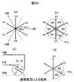
- FIG. 30A shows energization vectors V1 to V6 in modes 1 to 6.
- V1 is a voltage vector when mode 1 is selected (that is, a voltage vector during energization from the U phase to the V phase).
- Mode 1 is selected when the rotor magnetic flux ⁇ m exists in the region “M1” in FIG. 7B, but when a direct current is applied, the current magnetic flux as shown in FIG. The rotor is attracted to this and stops.
- the state fixed by the direct current of V1 is the same figure (d).
- the position of ⁇ m in FIG. 30 (d) is just on the boundary between mode 2 and mode 3. That is, by observing the electromotive voltage of the non-conducting phase at this position, a threshold for shifting from mode 2 to mode 3 can be obtained.
- the rotor phase at this time is ⁇ 30 [deg].
- the electromotive voltage of the non-energized phase V phase is sampled immediately after switching, it becomes a threshold value for switching from mode 2 to mode 3.
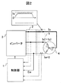
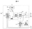
- This control device is intended to drive a three-phase AC motor 4. As shown in FIG. 1, it is roughly divided into a controller 1, a voltage detector 2, a DC power source 31, an inverter main circuit 32, and a gate. The inverter 3 including the driver 33 and the current sensor 5 are included. Further, the three-phase AC motor (PM motor) 4 to be driven and this control device constitute an AC motor system.
- a PM motor is taken as an example of a drive target.
- other types of AC motors can be applied as long as they are motors capable of obtaining magnetic saturation characteristics with respect to the rotor position.
- a controller 1 includes a multiplexer 11 that selects an electromotive voltage of a non-conducting phase from three phases, a threshold detector 12 that is a control block for detecting a threshold, and a speed / current controller that functions during normal driving. 13. It comprises a switch 14 for switching the threshold detection mode during normal driving, and a PWM (Pulse Width Modulation) generator 15 for pulse width modulating the voltage command.
- a PWM Pulse Width Modulation
- the switch 14 is switched to the “A” side, and switches the energized phase while comparing a preset threshold value with the electromotive voltage of the non-energized phase detected every sampling. At this time, the rotational speed control and torque control of the PM motor are performed in this block.
- the operation of the speed / current controller 13 basically uses a known technique as it is.
- the switcher 14 In the threshold detection mode, the switcher 14 is switched to the “B” side, energizes the PM motor in accordance with a preset flow, and acquires the “threshold” necessary for normal driving with high accuracy. .
- a direct current is passed from the U phase to the V phase.
- a magnetic flux is generated by a direct current inside the PM motor 4, and the rotor is moved and fixed so as to be attracted thereto.
- the energization mode of FIG. 2 since the U phase is positive and the V phase is negative, the energization is mode 1, and the voltage vector of V1 in FIG. 30A is applied.
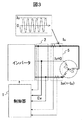
- the energized phase is switched, and energization from the U phase to the W phase is performed as shown in FIG.
- the AC frequency used for the threshold measurement corresponds to the carrier frequency at the time of PWM, but there is no problem as long as the electromotive voltage is sufficiently obtained. However, if the AC frequency is too low, vibration is generated in the rotor, which is not preferable. Although depending on the rotor structure, if a mechanical time constant is taken into consideration, there is no problem if the frequency is several hundred Hz or more.
- the amplitude of these alternating currents is changed, and the alternating current corresponding to the actual driving current is passed, thereby changing the conditions. Can be aligned.
- the rotor of the three-phase AC motor is temporarily fixed by DC energization, and then an AC current is applied between the two phases to acquire a threshold value.
- the threshold required for sensorless driving can be obtained with high accuracy by using the control apparatus for an AC motor according to this embodiment.
- a position sensorless driving system from low speed capable of high torque driving can be realized by sequentially switching energized phases using the threshold values thus obtained.
- the load torque and load of the PM motor are determined.
- An appropriate energized phase can be switched according to the current, and an algorithm capable of automatically collecting a threshold value for the switching can be realized.
- threshold acquisition is performed only once, and the thresholds of each of the six modes are set based on the value.
- the electromotive voltage tends to vary from phase to phase due to variations in the magnetic material of the motor, manufacturing errors, and the like.
- the detection circuit for detecting the electromotive voltage also varies from phase to phase, it is desirable to solve these problems.
- threshold values are acquired for all energization modes.
- DC energization is performed in mode 1 (A01), then the mode is switched to mode 2 and AC is applied (A02), and Vshp2 which is an electromotive voltage at that time is acquired (A03).
- DC energization is performed in mode 2 (A04), then switching to mode 3 and applying AC (A05), Vshp3 which is the electromotive voltage at that time is acquired (A06).
- DC energization, mode switching, AC application, and threshold sampling are repeated. In this way, if DC energization and AC energization are performed while changing the energization mode, a correct switching threshold value in all modes can be acquired.
- the rotor is temporarily fixed by passing a direct current between two phases of a three-phase AC motor, and then an alternating current is passed between two phases of a combination different from the two phases that are supplied with a direct current to obtain a threshold value.
- the threshold value is detected by performing the DC energization and the AC energization at least once in combination.
- the threshold required for sensorless driving can be accurately obtained in consideration of variation for each phase.
- a pulse for generating torque in the forward direction is a “forward pulse” and the reverse is a “reverse pulse”
- the resulting electromotive voltage is as shown in FIG.
- the forward rotation pulse is the same as the conventional one, the electromotive voltage due to the reverse rotation pulse is newly described.
- the forward rotation threshold by setting the reverse rotation threshold, it is possible to continuously drive forward and reverse rotation. This reversal drive has already been described in Reference 1 (“Low-speed sensorless permanent magnet synchronous motor using electromotive force due to magnetic saturation: forward / reverse drive near zero speed” 2011 IEEJ Industrial Application Division Conference Lecture Papers, No. 1-163, pp. I-715 to I-720 (2011)).
- FIG. 8 is a flowchart for automatically measuring the threshold value. Similar to FIG. 5, threshold values are obtained for all energization modes.
- the rotor is temporarily fixed by passing a direct current between the two phases of the three-phase AC motor, and then an alternating current is passed between the two phases that are different from the two phases that are supplied with the direct current.
- the threshold values are respectively acquired, and the direct current energization and the alternating current energization are performed at least once in combination to detect the threshold values.
- an operation of gradually increasing the amplitude of the alternating current is provided so that the rotor is not shocked as much as possible at the start of the alternating current application.
- FIG. 9 is a block diagram of the controller 1B which is a characteristic part of the present embodiment. By using this block instead of the controller 1 of FIG. 1, the fourth embodiment can be realized.
- a voltage limiter 16 is newly added, but the other blocks are the same as those in FIG.
- the voltage limiter 16 limits the rate of change in the amplitude of the AC voltage applied to the PM motor when the threshold is acquired.
- the current waveform gradually increases in a ramp shape as shown in FIG. 10, and the impact on the rotor can be eliminated.
- FIG. 11 is a block diagram of the controller 1C, which is a characteristic part of the present embodiment, and the fifth embodiment can be realized by using this block instead of the controller 1 of FIG.
- an AC frequency setter 17 and a current setter 18 are newly added, but the other blocks are the same as those in FIG.
- the AC frequency setter 17 checks whether or not the peak value of the phase current matches the value I0 set by the current setter 18, and if not, operates so as to lower the AC frequency. By this operation, it becomes possible to apply an alternating current having a magnitude necessary for obtaining the threshold value to the PM motor, and to ensure the detection accuracy of the threshold value.
- it has a function of presetting the alternating current amplitude, and means for adjusting the frequency of the alternating current so as to reach the set value of the alternating current amplitude.
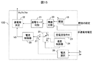
- FIG. 15 is a block diagram of a speed / current controller 13D, which is a characteristic part of the present embodiment, and the sixth embodiment can be realized by using this block instead of the speed / current controller 13 of FIG.
- the speed / current controller 13D includes a threshold setting unit 19 for setting a threshold, a threshold comparator 20 for comparing the detected value of the non-energized phase electromotive voltage with the threshold, and an output of the threshold comparator.
- the energization mode discriminator 21 for determining the current mode, the voltage command V0, and the energization phase determinator 22 for determining the three-phase voltage command so as to perform the energization operation specified by the energization mode discriminator 21;
- Constant current command I0 setter 23 to be set, speed controller 24 for outputting the current command to control the rotational speed of the PM motor 4, whether the current command to the PM motor is a constant current command or the output of the speed controller
- a switch 25 for switching, a current selector 26 for selecting a phase current to be controlled, a subtractor 27 for calculating a deviation between a current command and an actual current value, and an applied voltage V0 to the PM motor based on the current deviation. Calculated for the current controller 28, and
- the threshold value is detected as an optimum value for a predetermined current value, and the value is stored in the threshold value setter 19. Therefore, the energization mode is ideally switched by comparing the threshold value with the non-energized phase electromotive voltage. However, if the current value when the threshold is measured is different from the actually flowing current value, ideal switching cannot be performed. Therefore, the feature of this embodiment is that the PM motor is driven by a constant current so as to match the current obtained for the threshold.
- a current equal to the current value used for the threshold measurement is set.
- the switch 25 is switched to the “L” side, and a current command of a constant value I0 is always given to the current controller 28.
- ideal torque drive can always be realized.
- the conventional speed control can be realized by switching the switch 25 to the “H” side and switching to the sensorless drive based on the speed electromotive force.
- the switching speed ⁇ r0 is in the range of about 5% to 15%, although it depends on the characteristics of the PM motor.
- FIG. 16 shows the startup waveform when this embodiment is used.
- FIG. 16A shows a startup waveform from zero when the inertia of the mechanical system including the rotor is small. From the start time t0 to t1 when reaching the speed ⁇ r0, the current is controlled to be accelerated to a constant value I0, and then the current command is switched by the switch 25, and the speed controller 24 starts operation. After switching, the rotation speed increases according to the setting response of the speed controller and matches the speed command ⁇ r *. As shown in the figure, when the inertia is small, it is accelerated at a constant current by a constant current, and the low speed region passes in an instant.
- acceleration is performed by controlling the current so as to coincide with a preset value, and then the speed control function is operated to perform rotation control.
- Example 6 relates to an algorithm in the case of driving a PM motor by actually using the acquired threshold value, and can achieve a high torque drive that has never been achieved, while a low speed region becomes a constant current drive. There is a problem that the speed cannot be controlled. In this embodiment, an embodiment that solves this problem will be described.
- FIG. 17 is a block diagram of a speed / current controller 13E that is a characteristic part of the present embodiment, and the seventh embodiment can be realized by using this block in place of the speed / current controller 13 of FIG.
- the speed / current controller 13E is provided with a new harmonic generator 29 with respect to the speed / current controller 13D, and an adder 30 is added to add the output to the voltage command V0. Yes. Further, the constant current command I0 setting unit 23 and the switching unit 25 in FIG. 15 are deleted. The other components, the threshold setting unit 19, the threshold comparator 20, the energization mode discriminator 21, the energization phase determiner 22, the speed controller 24, the subtractor 27, and the current controller 28 are the same as those in the sixth embodiment. The same thing.
- driving with a constant current is not performed particularly in a low speed range.
- Current control is performed based on the speed controller 24 from the start.
- size of an electric current is determined by the speed controller, it becomes arbitrary values and may differ from the value set to the threshold value. Therefore, the harmonic generator 29 is introduced, the ripple component included in the current is manipulated, and the harmonic is intentionally applied so that the current peak is always obtained under the condition that the threshold is acquired.
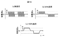
- the harmonic generator 29 increases the amount of harmonics when there is no load and adjusts the peak value to reach I0 (FIG. 18). (A)). Similarly, in the case of 50%, the amount of harmonics is adjusted so that the peak value reaches I0 ((b) in the figure). At 100% load, the current is equivalent to I0 with only the fundamental wave, so no harmonics are required ((c) in the figure).
- control is performed by adding a harmonic component to the voltage so that the peak value of the current flowing through the energized phase matches a preset value.
- Example 7 the amount of harmonics is controlled so that the peak value of the actual current matches the acquired threshold value, and speed control can be realized stably from the low speed range.
- this method is simple, since it is necessary to apply harmonics, no consideration is given to unnecessary electromagnetic noise and the point of increasing harmonic loss. In this embodiment, an embodiment that solves this problem will be described.
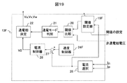
- FIG. 19 is a block diagram of a speed / current controller 13F, which is a characteristic part of the present embodiment. By using this block instead of the speed / current controller 13 of FIG. 1, Embodiment 8 can be realized.
- the speed / current controller 13F is mainly characterized in that a threshold value setter 19F is newly provided with respect to the above-described speed / current controller 13E.
- a harmonic generator 29, an adder 30 has been deleted.
- Threshold value setter 19F stores the threshold value in each energization mode.
- an appropriate threshold value for the current value is mapped and saved.
- the appropriate threshold value may change depending on the energized current, and the threshold value for this current is acquired in the above-described threshold detection mode. For example, in the process of gradually increasing the alternating current value as in Example 4, if a non-energized phase voltage is acquired and stored, the appropriate threshold value for the current can be easily acquired. .
- the threshold setting device 19F stores it as table data, and changes the threshold appropriately according to the current, so that the energization mode is always in the optimum state. Switching is possible.
- the relationship between the current value obtained in the threshold value detection mode and the threshold value is built in a data map or function, and the threshold value for the drive current is based on the data map or function. And the AC motor is driven. Therefore, according to this embodiment, it is possible to realize sensorless driving with high response from low speed and high accuracy without generating electromagnetic noise.
- Embodiment 9 of the present invention an AC motor control apparatus according to Embodiment 9 of the present invention will be described with reference to FIGS.
- an embodiment related to pre-adjustment for detecting a non-conduction phase induced voltage including threshold detection will be described.
- FIG. 21 (a) when a pulsed AC voltage Vvw is applied, a current as shown in FIG. 21 (b) is generated, and a non-conduction phase electromotive voltage Eu is generated.
- FIG. 3C ringing accompanying switching occurs in the actual electromotive voltage. Therefore, in order to avoid this ringing, it is necessary to sample the electromotive voltage after a predetermined time T after switching ((d) in the figure). If the predetermined time T is sufficiently short, the ringing voltage is sampled as shown in FIG. 5E, and a correct non-energized phase voltage cannot be detected.
- the sampling timing of the non-energized phase voltage Eu is shifted every calculation processing cycle to detect a period in which ringing occurs.
- FIG. 22 (a) shows a state in which the line voltage Vvw is applied for the period T0 at time t0. Since this voltage is repeatedly applied to the motor, an electromotive voltage with the same ringing is generated in the non-conducting phase every time.
- Eu is sampled at time t1 shifted by a minute time ⁇ t with respect to t0, and is sampled at time t2 further shifted by ⁇ t in the next cycle. By repeating such a process, it is possible to know the entire ringing waveform. If it is detected as a result of sampling that the fluctuation of the value has fallen, the size of the ringing period Tg can be detected.
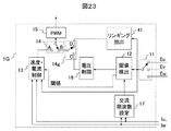
- FIG. 23 shows a block diagram of the controller 1G which is a characteristic part of the present embodiment.
- the ninth embodiment can be realized by using this block instead of the controller 1 of FIG.
- the main feature of the controller 1G is that a ringing extractor 41 and a switch 14g are newly provided to the controller 1C of FIG.
- this block is as follows. Before performing the threshold detection mode, the switch 14g is switched to the “D” side to extract the ringing time.
- the ringing extractor 41 repeatedly applies pulses as described above, and acquires a non-energized phase voltage while changing the sampling timing. As a result, the ringing convergence time T is acquired, and the minimum pulse width or harmonic frequency is set accordingly.
- the voltage waveform of the non-energized phase is sampled a plurality of times, the vibration range at the rising edge of the voltage waveform is detected, and the voltage detection timing is set so as to avoid the detection range . Further, the plurality of times of sampling is realized by sampling at every arithmetic processing cycle and gradually shifting the sampling timing.
- Embodiment 10 of the present invention will be described with reference to FIGS.
- an embodiment relating to a method for acquiring an overlapping period which is an adjustment element unique to 120-degree energization driving, will be described.
- the detection of the electromotive voltage and the comparison with the threshold value are impossible, and the time is “waiting”. Since it is necessary to sample the non-energized phase electromotive voltage while avoiding this period, it is necessary to set this period in advance. As can be seen from FIG. 24, during the overlap period, the non-energized phase electromotive voltage is always clamped to the positive or negative of the DC voltage, so it can be confirmed that it is the overlap period. This period is counted, and further, taking into account transient fluctuations, a margin of one or two samples is set as an overlapping period, and the non-conduction phase is detected.
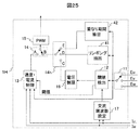
- FIG. 25 shows a block diagram of the controller 1H which is a characteristic part of the present embodiment.
- the tenth embodiment can be realized by using this block instead of the controller 1 of FIG.
- the main feature of the controller 1H is that an overlap period extractor 42 and a switch 14h are newly provided to the controller 1G of FIG.
- this block is as follows. Before executing the threshold detection mode or the ringing extraction mode, the switch 14h is switched to the “E” side to extract the overlap period.
- the overlap period extractor 42 changes the mode in the energized state as described above, and samples the non-energized phase voltage. Since the period during which the sampling result is clamped to the DC voltage of the inverter is an overlap period, the period is counted, and a margin of one or two samples is added to the overlap period after the clamp is released.
- the voltage of the non-energized phase when the energized phase is changed is sampled, the current decay period when the energized phase is changed is measured, and the voltage value of the non-energized phase An overlap period in which comparison with the threshold value with respect to the voltage value is not performed is extracted.
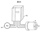
- FIG. 26 shows an AC motor system using a general-purpose inverter, which includes a three-phase AC power supply 44, a general-purpose inverter 45, and a PM motor 4.
- the general-purpose inverter 45 operates as a control device for the PM motor 4 (AC motor) to be driven.
- the general-purpose inverter 45 includes the controller 1, the voltage detector 2, the inverter 3, and the current sensor 5 described in the above embodiments. Note that the DC power source 31 in the inverter 3 in FIG. 1 obtains a DC source by rectifying and smoothing the three-phase AC power source 44. Moreover, the controller 1 which comprises the general purpose inverter 45 mounts the means of the Example demonstrated above.
- the threshold value of the PM motor 4 can be accurately extracted, and a high response from a low speed and a high torque drive are possible. Therefore, the embodiment of the present invention described above is particularly suitable for a device such as a general-purpose inverter on the assumption that various motors are connected. That is, sensorless driving with high torque and high response can be realized by connecting an arbitrary motor and extracting a threshold value.
- the embodiment described above is not limited to general-purpose inverters, but starts with rotational speed control of compressors (for air conditioning and refrigerators), fans, pumps (water pumps, oil pumps), spindle motors, and air conditioning equipment. It can also be applied to conveyors, elevators, extruders, machine tools and the like.
- the present invention is not limited to the above-described embodiments, and includes various modifications.
- the above-described embodiments have been described in detail for easy understanding of the present invention, and are not necessarily limited to those having all the configurations described.
- a part of the configuration of one embodiment can be replaced with the configuration of another embodiment, and the configuration of another embodiment can be added to the configuration of one embodiment.
- SYMBOLS 1 ... Controller, 2 ... Voltage detector, 3 ... Inverter, 4 ... Three-phase alternating current motor (PM motor), 5 ... Current sensor, 31 ... DC power supply, 32 ... Inverter main circuit, 33 ... Gate driver, 11 ... multiplexer, 12 ... threshold detector, 13 ... speed / current controller, 14 ... Switch, 15 ... PWM generator
Abstract
非通電相の起電圧に基づく交流電動機の回転子位置センサレスの、停止・低速域からの安定駆動を実現する方式として、通電相の切替閾値を適切に設定可能な自動調整手法を提案する。 上記課題を解決するために、三相交流電動機の二相を選択して通電し、残りの非通電相の電圧値と、該電圧値に対する閾値との比較に基づいて通電相を切替え、該三相交流電動機を回転駆動する交流電動機の制御装置において、前記閾値の設定は、前記閾値を検出するための閾値検出モードを備えるものとし、該閾値検出モードでは、前記三相交流電動機の回転子を直流通電によって一旦固定し、その後、二相間に交流電流を通電して前記閾値を取得する。
Description
本発明は、交流電動機システムに利用する電動機駆動技術に関する。
家電・産業・自動車などの分野では、例えば、ファン、ポンプ、圧縮機などの回転速度制御、ならびに電動パワーステアリングなどのトルクアシスト機器、さらには、製造装置におけるコンベア、昇降機、位置決め制御などにモータ駆動装置が用いられている。これらの分野のモータ駆動装置では、小形・高効率の交流電動機である永久磁石型同期電動機(以下、「PMモータ」と称する)が幅広く用いられている。しかし、PMモータを駆動するには、モータの回転子の磁極位置の情報が必要であり、そのための、レゾルバやホールIC等の位置センサが必須となる。近年では、この位置センサを用いずに、PMモータの回転数やトルク制御を行うセンサレス制御が普及している。
センサレス制御の実現によって、位置センサにかかる費用(センサそのもののコストや、センサの配線にかかるコスト、センサの取り付け調整作業にかかる費用)が削減でき、また、センサが不要となる分、装置の小型化や、劣悪な環境での使用が可能になるなどのメリットも生まれている。
現在、PMモータのセンサレス制御は、ロータが回転することによって発生する誘起電圧(速度起電圧)を直接検出し、回転子の位置情報としてPMモータの駆動を行う方式や、PMモータの数式モデルから、回転子位置を推定演算する位置推定技術などが採用されている。
PMモータの発生する誘起電圧に基づくセンサレス方法としては、誘起電圧の零クロスに基づく方式がある。この方式は、PMモータを120度通電で駆動し、通電していない相の電圧を検出し、その電圧が零クロスするタイミングをコンパレータによって求め、位相情報を得るものである。しかし、この方式は速度起電圧に基づく方式であるために、停止・低速域ではPMモータを駆動することができない。
また、速度起電圧を用いない位置センサレス方式が提案されており、速度起電圧の発生しない零速度域の位置センサレス方式として、例えば、特開2009-189176号公報(特許文献1)がある。特許文献1では、PMモータの2つの相にパルス電圧を印加すると、PMモータの回転子の位置に応じた起電圧が、通電していない非通電相に発生する。よって、この起電圧(磁気飽和起電圧)を観測することで、回転子の位置(角度)に対する依存性が観測され、低速域での位置センサレス駆動が可能となる。磁気飽和起電圧は、非通電相に発生する電圧であるため、制御側で検出相を選択して、電圧を読み込む必要がある。よって、通電相の切替えを、非通電相の磁気飽和起電圧の大きさを観測しながら、予め設定している閾値に到達した時点で行うようにすれば、位置センサレスでの駆動が実現できる。ここで、通電相の切替えには、「閾値」の設定精度が重要となる。
特開2012-10477号公報(特許文献2)には、この閾値に関する自動調整機能が開示されている。特許文献2では、以下の手順で閾値の自動調整を行う。まず初めに、例えばモード1において直流電流を流し、その通電モードの位置に回転子を引き付けておく。次に、モードを一つ進めて、同じように直流を通電する。その際、モードを切替えた直後の非通電相の電圧が、閾値電圧に一致する。以降その繰り返しによって、特許文献1で重要となる閾値の値を実機から取得可能になる。
特許文献1は、モータが停止・低速状態において、脱調することなく駆動力を発することができる。しかし、センサレス駆動における重要な設定定数である閾値の自動調整に関する記載がない。
特許文献2は、前述の閾値の自動調整に関する内容が開示されているが以下の問題がある。
第一に、ある通電モードにおいて直流を印加することによって回転子を一旦固定し、その後、次の通電モードに切替えて直流を通電し、その切替直後の起電圧を採取するため、もし、PMモータのイナーシャが小さい場合には、切替えと同時に回転子が移動してしまい、正確な閾値を採取することができなくなってしまう。
第二に、200V級のPMモータの場合、回転子の磁石量を最適化(最小化)して設計しており、代わりに固定子の巻数を上げて、回転トルクを得るような設計が多い。その場合、固定子の電流値によってPMモータの磁束量が大きく変化し、結果的に閾値の適正な値も変化してしまう。すなわち、特許文献1で開示されたセンサレス制御を実現する上で、閾値そのものを、PMモータの回転トルク、あるいは電流値に応じて最適値に設定する必要がある。そうでないと、PMモータの仕様を満たす十分なトルクが得られないばかりか、脱調や不安定な振動を招く可能性がある。
本発明の目的は、零速度近傍において、回転子位置センサを用いずに、高トルクを実現し、かつ高安定な交流電動機の駆動制御装置およびそれを用いた交流電動機システムを提供することにある。
上記課題を解決するために、例えば特許請求の範囲に記載の構成を採用する。本発明は上記課題を解決する手段を複数含んでいるが、その一例を挙げるならば、三相交流電動機の二相を選択して通電し、残りの非通電相の電圧値と、該電圧値に対する閾値との比較に基づいて通電相を切替え、該三相交流電動機を回転駆動する交流電動機の制御装置において、前記閾値の設定は、前記閾値を検出するための閾値検出モードを備えるものとし、該閾値検出モードでは、前記三相交流電動機の回転子を直流通電によって一旦固定し、その後、二相間に交流電流を通電して前記閾値を取得する。
本発明によれば、停止状態からの高速度域までの広い範囲にわたり、高トルクでかつ安定な制御装置およびそれを用いた交流電動機システムを提供できる。
まず、本発明の前提となる、速度起電圧を用いない位置センサレス方式について、図面を用いて説明する。
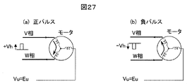
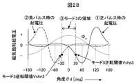
特許文献1では、図27(a)、(b)に示すように、PMモータの2つの相にパルス電圧を印加すると、PMモータの回転子の位置に応じた起電圧が、通電していない非通電相に発生する。図27ではU相が非通電相になっている。この起電圧は、PMモータの回転子に取り付けられている永久磁石磁束と、通電電流の関係によって、モータ内のインダクタンスが微小に変化することで発生する電圧であり、停止状態においても観測可能である。よって、この磁気飽和起電圧を観測することで、図28に示すような回転子の位置(角度)に対する依存性が観測され、低速域での位置センサレス駆動が可能となる。この起電圧を、回転子が回転することで発生する速度起電圧と区別するために、磁気飽和起電圧と呼んでいる。磁気飽和起電圧は、非通電相に発生する電圧であるため、制御側で検出相を選択して、電圧を読み込む必要がある。
特許文献1では、図27(a)、(b)に示すように、PMモータの2つの相にパルス電圧を印加すると、PMモータの回転子の位置に応じた起電圧が、通電していない非通電相に発生する。図27ではU相が非通電相になっている。この起電圧は、PMモータの回転子に取り付けられている永久磁石磁束と、通電電流の関係によって、モータ内のインダクタンスが微小に変化することで発生する電圧であり、停止状態においても観測可能である。よって、この磁気飽和起電圧を観測することで、図28に示すような回転子の位置(角度)に対する依存性が観測され、低速域での位置センサレス駆動が可能となる。この起電圧を、回転子が回転することで発生する速度起電圧と区別するために、磁気飽和起電圧と呼んでいる。磁気飽和起電圧は、非通電相に発生する電圧であるため、制御側で検出相を選択して、電圧を読み込む必要がある。
図29に、回転子の位置θdに対する通電相、非通電相、磁気飽和起電圧の関係を示す。通電相は、回転力が最も大きくなる2つの相をθdに応じて選択している。その通電相の切替えは、非通電相の磁気飽和起電圧の大きさを観測しながら、予め設定している閾値、すなわち図29におけるVshp1~Vshp6、に到達した時点で行うようにすれば、位置センサレスでの駆動が実現できる。
例えば、図29において、回転子の位置がモード1にある場合(210[deg]≦θd≦270[deg])には、U相からV相への通電がなされ、PMモータには正転方向への回転力が発生する。回転子が回転するに従い、モード1での非通電相であるW相の起電圧は減少を開始し、やがて、θd=270[deg]にて閾値Vshp1に一致する。この一致により、通電モードの切替えトリガーが発生し、通電相が切替えられる。ここで明らかなように、通電相の切替えには、「閾値」の設定精度が重要となる。
特許文献2では、この閾値に関する自動調整機能が公開されている。閾値は、基本的にモータの磁気回路特性によって定まるものであるが、磁性材料のばらつきや、作り込み誤差、あるいは電圧検出回路の精度にも依存して変化してしまう。そこで、PMモータやそれを駆動するインバータの個体ばらつきを補正するための自動調整機能が望まれる。
特許文献2では、以下の手順で閾値の自動調整を行う。
まず初めに、例えばモード1において直流電流を流し、その通電モードの位置に回転子を引き付けておく。次に、モード一つ進めて、同じように直流を通電する。その際、モードを切替えた直後の非通電相の電圧が、閾値電圧に一致する。
図30(a)は、モード1~6の通電ベクトルV1~V6を示している。例えば、V1は、モード1を選択した時の電圧ベクトル(すなわち、U相からV相への通電時の電圧ベクトル)である。モード1を選択するのは、同図(b)における「M1」の領域に回転子磁束Φmが存在する場合であるが、直流を流し込むことで同図(c)のような電流磁束がモータ内部に発生し、これにロータが引き付けられて、停止する。V1の直流によって固定された状態が同図(d)である。
この図30(d)のΦmの位置は、ちょうどモード2とモード3の境界上にある。すなわち、この位置での非通電相の起電圧を観測すれば、モード2からモード3へ移行するための閾値を得ることができる。
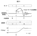
図31に示すように、モード1の状態で直流を通電して、回転子を固定しておくと、この時の回転子位相は-30[deg]である。ここで通電相をモード2に切替え、非通電相V相の起電圧を切替直後にサンプリングすると、それはすなわち、モード2からモード3への切替えの閾値となる。
そのままモード2への直流通電を続けることで、回転子は+30[deg]の位置に移動する。今度は、モード3へ切替えることで、モード3からモード4への切替閾値が得られる。この繰り返しによって、特許文献1で重要となる閾値の値を実機から取得可能になる。
以上の特許文献2においては、前述したように、切替直後の起電圧を採取する際に回転子が移動してしまい正確な閾値を採取することができない点、閾値そのものをPMモータの回転トルクや電流値に応じて最適値に設定する必要がある点等の課題があり、それを解決するための本発明の実施例を、以下、図面を用いて説明する。
図1~4を用いて、本発明の実施例1に関わる交流電動機の制御装置について説明する。
この制御装置は、三相交流電動機4の駆動を目的とするものであり、図1に示すように、大別すると、制御器1、電圧検出器2、直流電源31とインバータ主回路32とゲート・ドライバ33を含むインバータ3、電流センサ5を含んで構成される。また、駆動対象である三相交流電動機(PMモータ)4と、この制御装置で交流電動機システムを構成する。
尚、駆動対象としては、本実施例ではPMモータを例に挙げるが、回転子位置に対する磁気飽和特性が得られる電動機であれば、他の種類の交流電動機であっても適用可能である。
図1において、制御器1は、三相から非通電相の起電圧を選択するマルチプレクサー11、閾値を検出するための制御ブロックである閾値検出器12、通常駆動時に機能する速度・電流制御器13、通常駆動時と、閾値検出モードを切替える切替器14、電圧指令をパルス幅変調するPWM(Pulse Width Modulation)発生器15からなる。
通常駆動の場合、切替器14は「A」側に切替えられ、予め設定された閾値と、サンプリング毎に検出される非通電相の起電圧とを比較しながら、通電相の切替えを行う。この時、PMモータの回転数制御やトルク制御が本ブロック内で実施される。速度・電流制御器13の動作は、基本的には公知技術をそのまま用いるものである。
また、閾値検出モードでは、切替器14は「B」側に切替えられ、予め設定されたフローに従い、PMモータへの通電を実施し、通常駆動時に必要となる「閾値」を高精度に取得する。
このフローの詳細を図2、3を用いて説明する。まず、図2に示すように、U相からV相へ直流電流を通電する。この祭、PMモータ4の内部では、直流電流による磁束が発生し、それに引き付けられるように、回転子が移動して固定される。図2の通電モードは、U相が正、V相が負であるから、モード1の通電となり、図30(a)におけるV1の電圧ベクトルを印加していることになる。この位置(θd=-30[deg])に回転子は一旦固定される。次に、通電相を切替え、図3に示すようにU相からW相への通電を行う。ただし、この場合には、平均が零となる交流を印加する。U相からW相への通電はモード2となるが、この時に固定されている回転子位置θd=-30[deg]は、モード2からモード3への境界上にある。よって、ここでの非通電相起電圧は、モード2からモード3への切替時の閾値に一致するため、この交流電流の通電によって閾値が取得できる。
印加している電流が交流であるため、発生トルクの平均は零であり、回転子は回転せず、モード1で位置を固定されたままの状態を保つ。この点が特許文献2との大きな違いである。よって、回転子が移動しないことから、精度よく閾値の取得が可能である。
閾値測定のために流す交流の周波数は、PWMを行う際のキャリア周波数相当が適切と考えているが、起電圧が十分得られる周波数であれば問題ない。ただし、交流の周波数が低すぎると、回転子に振動を発生させるため好ましくない。回転子構造にもよるが、機械的な時定数を考慮すれば、数100Hz以上の周波数であれば問題ない。
また、閾値の適正値がPMモータの駆動条件(特に電流の大きさ)に応じて変化する場合、これら交流電流の振幅を変化させ、実際の駆動電流に相当する交流を流すことで、条件をそろえることができる。
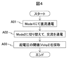
これらの動作をフロー図で示すと、図4となる。まず直流通電を実施し(A01)、回転子を固定し、その後、通電モードを切替えて交流を通電する(A02)。その状態で得られた非通電相(W相)の起電圧が、モード2からモード3への切替閾値になる。図29に示したように、PMモータの閾値は、原理的にはすべて対象となるため、一つの閾値で6つのモードそれぞれの切替閾値が得られることになる。
すなわち、三相交流電動機の回転子を直流通電によって一旦固定し、その後、二相間に交流電流を通電して閾値を取得する。
以上のように、本実施例による交流電動機の制御装置を用いれば、センサレス駆動に必要となる閾値を精度よく取得できる。こうして得られた閾値を用いて、通電相を順次切替えることで、高トルク駆動が可能な低速からの位置センサレス駆動システムが実現できる。
すなわち、本実施例によれば、三相のうちの二相間に通電し、残りの非通電相の起電圧に基づいて通電相の切替タイミングを決定するセンサレス制御において、PMモータの負荷トルクや負荷電流に応じて、適切な通電相の切替えが可能となり、また、その切替えのための閾値の値を、自動的に採取可能なアルゴリズムが実現できる。
この結果、様々な種類のPMモータに対して、停止状態からの高速度域までの広い範囲にわたり、高トルクでかつ安定な交流電動機駆動システムを提供できる。
次に、図5を用いて、本発明の実施例2に関わる交流電動機の制御装置について説明する。
前述した図4では、閾値取得を1回のみ実施し、その値に基づいて、6つのモードのそれぞれの閾値を設定するものであった。しかし、実際のPMモータでは、モータの磁性材料のばらつきや、作り込みの誤差などによって、相毎に起電圧がばらばらになる傾向にある。特に、起電圧を検出する検出回路にも相毎のばらつきがあるため、これらを解決することが望ましい。
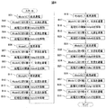
そこで、図5に示すように、全通電モードに対して、閾値の取得を行うようにする。図5において、まず初めにモード1にて直流通電を行い(A01)、次にモード2に切替えて交流を印加(A02)、その時の起電圧であるVshp2を取得する(A03)。次に、モード2にて直流通電を行い(A04)、次にモード3に切替えて交流を印加(A05)、その時の起電圧であるVshp3を取得する(A06)。以降、直流通電、モードを切替えて交流を印加、閾値採取、を繰り返す。このように、直流通電と交流通電を、通電モードを変えながら実施すれば、全モードにおける正しい切替閾値が取得可能である。
すなわち、三相交流電動機の二相間に直流を通電することで回転子を一旦固定し、その後、直流を通電した二相とは異なる組み合わせの二相間に交流電流を通電して、閾値を取得し、これらの直流通電ならびに交流通電を少なくとも1回以上の組合せで実施して閾値を検出する。
以上、本実施例による交流電動機の制御装置を用いれば、センサレス駆動に必要となる閾値を相毎のばらつきを考慮した上で精度よく取得可能になる。
次に、図6、7、8を用いて、本発明の実施例3に関わる交流電動機の制御装置について説明する。すなわち、実施例1、2は、いずれも回転子の回転方向が固定(正転方向)であったのに対し、本実施例では逆転まで考慮した閾値の設定方法を提供する。
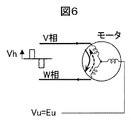
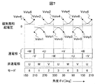
零速度付近で、回転子の速度やトルクを制御するには、正確な回転子位置がわからなければならない。正転、逆転を実現するため、図6に示すバイ・ポーラPWMを採用する。バイ・ポーラとは、正側、負側の双方にパルスを必ず立てるというPWMの方式である。この双方のパルスに対して、起電圧をそれぞれ観測すると、図7のような関係が得られる。正転方向にトルクを発生させるパルスを「正転パルス」、その逆を「逆転パルス」とすると、得られる起電圧は図7にようになる。ここで正転パルスは従来通りのものだが、逆転パルスによる起電圧が新たに記載されている。正転の閾値と同様、逆転の閾値も設定することで、正転・逆転の連続駆動も可能になる。尚、この逆転駆動に関する記載は、すでに文献1(「磁気飽和による起電圧を利用した永久磁石同期モータの低速センサレス~零速度近傍の正・逆転駆動~」平成23年電気学会産業応用部門大会講演論文集、No. 1-163、pp. I-715~I-720 (2011))にて公開されている。
零速度付近で、回転子の速度やトルクを制御するには、正確な回転子位置がわからなければならない。正転、逆転を実現するため、図6に示すバイ・ポーラPWMを採用する。バイ・ポーラとは、正側、負側の双方にパルスを必ず立てるというPWMの方式である。この双方のパルスに対して、起電圧をそれぞれ観測すると、図7のような関係が得られる。正転方向にトルクを発生させるパルスを「正転パルス」、その逆を「逆転パルス」とすると、得られる起電圧は図7にようになる。ここで正転パルスは従来通りのものだが、逆転パルスによる起電圧が新たに記載されている。正転の閾値と同様、逆転の閾値も設定することで、正転・逆転の連続駆動も可能になる。尚、この逆転駆動に関する記載は、すでに文献1(「磁気飽和による起電圧を利用した永久磁石同期モータの低速センサレス~零速度近傍の正・逆転駆動~」平成23年電気学会産業応用部門大会講演論文集、No. 1-163、pp. I-715~I-720 (2011))にて公開されている。
本実施例は、これら2種類の閾値(正転方向の閾値Vshp1~6、ならびに逆転方向の閾値Vshn1~6)の自動調整を実現する。図8がその閾値を自動計測するフロー図である。図5と同様に、すべての通電モードに対して閾値を求めている。
すなわち、図8において、まず初めにモード1に直流通電を行い(B01)、次にモード2において交流を印加し(B02)、モード2から3への閾値を設定する。その後、そのままの状態でモードを3に切替え、再び交流を印加する(B03)。この時得られるのは、モード3からモード2への逆転の閾値である。これは図30(d)に示す通り、モード1で固定した回転子の位置は、モード2と3の境界線上であるため、モード2から3への正転方向の閾値と、モード3から2への逆転方向の閾値の両方が一度に取得可能である。
この閾値取得動作をモード2以降も同時に続けていくことで、PMモータの全モードにおける正転、ならびに逆転方向の閾値が取得可能である。
すなわち、三相交流電動機の二相間に直流を通電することで回転子を一旦固定し、その後、直流を通電した二相とは異なる組み合わせの2通りの二相間に、それぞれ交流電流を通電して、閾値をそれぞれ取得し、これらの直流通電ならびに交流通電を少なくとも1回以上の組合せで実施して閾値を検出する。
次に、図9、10を用いて、本発明の実施例4に関わる交流電動機の制御装置について説明する。
これまでの実施例では、閾値取得のために交流を通電することで、実際のPMモータ駆動時と同等の大きさの電流まで流すことが可能であり、より精度の高い閾値が取得できることを述べた。交流電流は平均値が零であるため、平均の回転力を発生しないが、高振幅の交流をステップ状に一気に与えることで、回転子が瞬間的に移動してしまう場合がある。この動きは、回転子のイナーシャや摩擦力などによって様々であるが、ソフトスタートをかけて、なるべく急峻な変動を与えない方が望ましい。
本実施例では、交流印加開始時において、なるべく回転子にショックを与えないよう、交流電流の振幅を徐々に増加させる動作を提供する。
図9は、本実施例の特徴部分である制御器1Bのブロック図であり、本ブロックを図1の制御器1の代わりに用いることで、第4の実施例が実現できる。
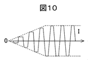
図9では、新たに電圧制限器16が追加されているが、それ以外のブロックは図1のものと同一のものである。電圧制限器16は、閾値取得時にPMモータに印加する交流電圧の振幅の変化率を制限するものである。この電圧制限器16の導入により、電流波形は、図10のようにランプ状に徐々に増加し、回転子への衝撃を無くすことができる。
以上のように、本実施例によれば、交流印加開始時の回転子位置変動を抑制することができ、それによって閾値の検出誤差をさらに低減できる。
次に、図11~14を用いて、本発明の実施例5に関わる交流電動機の制御装置について説明する。
これまでの実施例では、閾値取得のために交流を通電することで、実際のPMモータ駆動時と同等の大きさの電流まで流すことが可能であり、より精度の高い閾値が取得できることを述べた。しかし、交流を印加した時の電流は、交流の振幅だけでなく、周波数に対しても依存性があるため、条件によっては十分な交流電流が流せない場合が発生する。
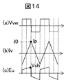
この現象を、図12~14を用いて説明する。例えば、図12のようにV相とW相の線間にパルス状の交流電圧を印加した場合(通電モード3の条件)、相電流Ivが発生するが、その最大値(ピーク値)Ipが所定値I0に満たないとする。そこで、図13のように、最大限までパルス幅を拡大するが、やはりI0には到達しない。すなわち、この周波数で十分な交流電流を流すことは不可能であることがわかる。その場合、図14のように、交流の周波数を下げることで、最大電流を所望の値にまで流すことが可能になる。
これら図12~14の動作を、自動的に実施するのが、本実施例5である。
図11は、本実施例の特徴部分である制御器1Cのブロック図であり、本ブロックを図1の制御器1の代わりに用いることで、実施例5が実現できる。
図11では、新たに交流周波数設定器17と、電流設定器18が追加されているが、それ以外のブロックは図1のものと同一のものである。交流周波数設定器17は、相電流のピーク値が電流設定器18にて設定された値I0に一致しているかどうかをチェックし、一致していなければ、交流周波数を下げるように動作する。この動作によって、閾値取得に必要な大きさの交流電流をPMモータに印加できるようになり、閾値の検出精度を確保できるようになる。
すなわち、交流電流振幅を予め設定する機能を備え、該交流電流振幅の設定値に至るように、前記交流電流の周波数を調整する手段を備える。
次に、図15、16を用いて、本発明の実施例6に関わる交流電動機の制御装置について説明する。
これまでの実施例では、高精度な閾値取得のための手段について述べてきたが、本実施例では、その取得した閾値を実際に用いてPMモータを駆動する場合のアルゴリズムに関して述べる。
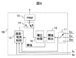
図15は、本実施例の特徴部分である速度・電流制御器13Dのブロック図であり、本ブロックを図1の速度・電流制御器13の代わりに用いることで、実施例6が実現できる。
図15において、速度・電流制御器13Dは、閾値を設定する閾値設定器19、非通電相起電圧の検出値と閾値と比較する閾値比較器20、閾値比較器の出力に基づき、PMモータへの通電モードを決定する通電モード判別器21、電圧指令V0、ならびに通電モード判別器21によって指定された通電動作を行うよう、三相電圧指令を決定する通電相決定器22、起動時の電流を設定する定電流指令I0設定器23、PMモータ4の回転数制御を行うため、電流指令を出力する速度制御器24、PMモータへの電流指令を定電流指令か、速度制御器の出力かを切替える切替器25、制御する相電流を選択する電流選択器26、電流指令と実際の電流値との偏差を演算する減算器27、電流偏差に基づいて、PMモータへの印加電圧V0を演算する電流制御器28、から構成される。
本ブロックの動作は以下の通りである。
これまでの実施例で述べた通り、閾値は所定の電流値に対して最適な値として検出されており、その値は閾値設定器19に格納されている。よって、この閾値と非通電相起電圧との比較によって、通電モードは理想的に切替えられる。ただし、閾値を測定した時の電流値と、実際に流れている電流値が異なっていると、理想的な切替えが成されないことになる。よって、閾値を取得した電流に一致するように、定電流によるPMモータ駆動を行うのが、本実施例の特徴である。
定電流指令I0設定器23において、閾値測定に用いた電流値に等しい電流を設定しておく。起動時は、切替器25が「L」側に切替えられており、常に一定値I0の電流指令が電流制御器28へ与えられる。この結果、駆動電流と設定閾値の条件は一致するため、常に理想的なトルク駆動が実現できるようになる。また、回転数が上昇し、速度起電圧が大きくなったところで、切替器25を「H」側に切替え、速度起電圧によるセンサレス駆動に切替えれば、従来通りの速度制御が実現可能になる。この切替え速度ωr0は、PMモータの特性にも依存するが、5%から15%程度の範囲である。
図16に、本実施例を用いた場合の起動波形を示す。図16(a)は、回転子を含めた機械系のイナーシャが小さい場合の零からの起動波形である。起動開始時刻t0から、速度ωr0に到達するt1までは、電流を一定値I0に制御して加速し、その後、切替器25によって電流指令が切替わり、速度制御器24が動作を開始する。切替え後、回転速度は速度制御器の設定応答に従って上昇し、速度指令ωr*に一致する。図のように、イナーシャが小さい場合には、定電流にて一気に加速され、低速域は一瞬で通り過ぎる。
これに対し、イナーシャが大きな場合には、図16(b)のようにt1までの時間が長くなるが、設定電流に応じたトルクでの加速が可能である。
すなわち、交流電動機の通常駆動時における起動時には、電流を予め設定した値に一致するように制御して加速し、その後、速度制御機能を動作させて回転制御を行う。
このように、従来、低速域での高トルク化が難しかったセンサレス駆動であるが、起動電流と、それに対して適切な閾値を設定することで、無駄のない加速特性が得られるようになり、より安定でかつ高応答な交流電動機の制御装置が実現できる。
次に、図17、18を用いて、本発明の実施例7に関わる交流電動機の制御装置について説明する。
実施例6では、取得した閾値を実際に用いてPMモータを駆動する場合のアルゴリズムに関するものであり、これまでにない高トルク駆動が実現できる一方、低速域は一定電流駆動となってしまうため、速度制御ができないという問題がある。本実施例では、この問題を解決する実施例を示す。
図17は、本実施例の特徴部分である速度・電流制御器13Eのブロック図であり、本ブロックを図1の速度・電流制御器13の代わりに用いることで、実施例7が実現できる。
図17において、速度・電流制御器13Eは、前述の速度・電流制御器13Dに対して、新たに高調波発生器29を設け、その出力を電圧指令V0に加算する加算器30を追加している。さらに、図15における定電流指令I0設定器23、切替器25は削除されている。その他の部品である、閾値設定器19、閾値比較器20、通電モード判別器21、通電相決定器22、速度制御器24、減算器27、電流制御器28は、それぞれ実施例6のものと同じものである。
本ブロックの動作は以下の通りである。
本実施例では、特に低速域において、一定電流による駆動は実施しない。起動時から速度制御器24に基づいて電流制御が実施される。その場合、電流の大きさは、速度制御器によって決定されるため任意の値となり、閾値に設定された値と異なる場合が生じる。そこで、高調波発生器29を導入し、電流に含まれるリプル成分を操作し、常に、閾値を取得した条件の電流ピークとなるように意図的に高調波を印加する。
その様子を図18に示す。閾値取得時の電流をI0とし、その大きさを100%電流とすると、無負荷時には高調波発生器29において高調波量を増やしておき、ピーク値がI0に到達するように調整する(図18(a))。同様に、50%の場合にも高調波量を調整して、ピーク値がI0に到達するようにする(同図(b))。100%負荷時には、基本波のみでI0相当の電流となるため、高調波は不要になる(同図(c))。
すなわち、交流電動機の通常駆動時、前記通電相を流れる電流のピーク値が、予め設定した値に一致するように高調波成分を電圧に加算して制御を行う。
このように、高調波発生器29によって電流ピーク値を調整することで、低速からの任意の速度制御、トルク制御が実現できるようになる。
次に、図19、20を用いて、本発明の実施例8に関わる交流電動機の制御装置について説明する。
実施例7では、取得した閾値に実電流のピーク値が一致するように高調波量を制御し、低速域から安定に速度制御を実現するものであった。この方式は簡便ではあるものの、高調波を印加する必要があるため、不必要な電磁騒音や、高調波損失を増加させる点について考慮されていない。本実施例では、この問題を解決する実施例を示す。
図19は、本実施例の特徴部分である速度・電流制御器13Fのブロック図であり、本ブロックを図1の速度・電流制御器13の代わりに用いることで、実施例8が実現できる。
図19において、速度・電流制御器13Fは、前述の速度・電流制御器13Eに対して、新たに閾値設定器19Fを設けているのが主な特徴であり、高調波発生器29、加算器30は削除されている。
本ブロックの動作は以下の通りである。
閾値設定器19Fは、各通電モードにおける閾値を格納しているが、ここでは、電流値に対する適切な閾値をマップ化して保存している。図20に示すように、閾値の適正値は、通電する電流によって変化する場合があり、この電流に対する閾値を前述の閾値検出モードにおいて取得する。例えば、実施例4のように、交流電流値を徐々に増加させる過程において、非通電相電圧を取得し、それらの値を保存していけば、電流に対する適切な閾値は容易に取得可能である。このようにして得られた電流値に対する閾値情報を元に、閾値設定器19Fにテーブルデータとして記憶させておき、電流に応じて適宜、閾値を変更することで、常に最適な状態での通電モード切替えが可能になる。
すなわち、交流電動機の通常駆動時、閾値検出モードで得られた電流値と閾値の関係を、データマップ、もしくは関数にて内蔵しておき、該データマップ、もしくは関数に基づいて、駆動電流に対する閾値を算出して、交流電動機を駆動する。
よって、本実施例によれば、電磁騒音を生じることもなく、低速からの高応答、高精度なセンサレス駆動が実現できる。
よって、本実施例によれば、電磁騒音を生じることもなく、低速からの高応答、高精度なセンサレス駆動が実現できる。
次に、図21~23を用いて、本発明の実施例9に関わる交流電動機の制御装置について説明する。本実施例では、閾値検出を含めた非通電相起電圧検出のための、事前調整に係わる実施例を示す。
図21(a)に示すように、パルス状の交流電圧Vvwを印加した場合、同図(b)のような電流が発生し、非通電相起電圧Euが発生する。同図(c)に示すように、実際の起電圧にはスイッチングに伴うリンギングが発生する。そこでこのリンギングを避けるために、スイッチング後、所定時間Tをおいて起電圧をサンプリングする必要がある(同図(d))。もし、この所定時間Tが十分短い場合、同図(e)のように、リンギング中の電圧をサンプリングしてしまい、正しい非通電相電圧を検出できないことになる。
これらのリンギング周波数は、数10kHz~数MHzの領域であり、サンプリング周期が数100μsであるモータ制御の演算周期では、とても検出は不可能である。
そこで、演算処理周期毎に非通電相電圧Euのサンプリングタイミングをずらしていき、リンギングの発生している期間を検出することにする。
図22(a)は、時刻t0において、線間電圧Vvwを期間T0だけ印加した様子を示している。モータには、この電圧が繰り返し印加されるため、毎回同じリンギングを伴う起電圧が非通電相に発生する。まず初めに、t0に対して微小時間Δtだけずらしたt1の時刻でEuをサンプリングし、次の周期では、さらにΔtずらしたt2の時刻でサンプリングする。このような処理を繰り返すことで、リンギングの波形の全容を知ることが可能である。サンプリングの結果、値の変動が収まったことを検出すれば、リンギング期間Tgの大きさが検出できる。
図23に、本実施例の特徴部分である制御器1Gのブロック図を示す。本ブロックを図1の制御器1の代わりに用いることで、実施例9が実現できる。
図23において、制御器1Gは、図11の制御器1Cに対して、新たにリンギング抽出器41、ならびに切替器14gを設けているのが主な特徴である。
本ブロックの動作は次の通りである。閾値検出モードを実施する前に、切替器14gを「D」側に切替えて、リンギング時間の抽出を実施する。リンギング抽出器41では、前述の通りにパルスの印加を繰り返し実施し、その間、非通電相電圧をサンプリングのタイミングを変えて取得する。その結果、リンギングの収束時間Tを取得し、それに合わせて最小パルス幅の設定、あるいは高調波周波数の設定を実施する。
すなわち、閾値検出モードの開始時の動作として、非通電相の電圧波形を複数回数サンプリングし、電圧波形の立ち上がり時の振動範囲を検出し、該検出範囲を避けるように、電圧検出タイミングを設定する。また、前記複数回数サンプリングは、演算処理周期毎にサンプリングを行うものとし、かつ、サンプリングタイミングを徐々にずらすことで実現する。
以上のように、本実施例によれば、リンギング時間を自動的に抽出することが可能であり、より高精度な閾値の取得、ならびに高応答、かつ高安定な交流電動機の制御装置が実現できる。
次に、図24、25を用いて、本発明の実施例10に関わる交流電動機の制御装置について説明する。本実施例では、120度通電駆動に特有の調整要素である重なり期間の取得方法に関する実施例を示す。
図24に示すように、時刻t0にて通電モードをモード1からモード2に切替えた場合、U相の電流は継続して流れ続けるが、V相からW相への電流の切替えが発生する。この際、V相の電流は一瞬で零にはならず、フリーホイールダイオードを経由して、徐々に減少する。同時にW相の電流が立ち上がるため、一瞬だけ三相に同時に電流が流れることになる。この期間(図24のt0からtsの間の期間)を重なり期間と言う。この期間は、通電相を変更した際の電流の減衰期間であり、本来非通電相となるべきV相が通電しているため、非通電相の起電圧検出ができない期間となる。
よって、この期間は起電圧の検出と閾値との比較は不可能であり、「待ち」の時間となる。この期間を避けて、非通電相起電圧をサンプリングする必要があるため、予めこの期間を設定しておく必要がある。図24からもわかるように、重なり期間中は、非通電相起電圧が直流電圧の正か負に必ずクランプされているため、重なり期間であることが確認できる。この期間をカウントし、さらに過渡変動も考慮して1、2サンプル分の余裕を持たせて重なり期間として設定し、非通電相の検出を実施する。
図25に、本実施例の特徴部分である制御器1Hのブロック図を示す。本ブロックを図1の制御器1の代わりに用いることで、実施例10が実現できる。
図25において、制御器1Hは、図23の制御器1Gに対して、新たに重なり期間抽出器42、ならびに切替器14hを設けているのが主な特徴である。
本ブロックの動作は次の通りである。閾値検出モード、あるいはリンギング抽出モードを実施する前に、切替器14hを「E」側に切替えて、重なり期間の抽出を実施する。重なり期間抽出器42では、前述の通りに通電状態でモード変更を実施し、非通電相電圧をサンプリングする。サンプリング結果がインバータの直流電圧にクランプされている期間は重なり期間であるためその期間をカウントし、クランプが解除されたところから1、2サンプル分の余裕を加えて重なり期間とする。
すなわち、閾値検出モードの実施前に、通電相を変更した際の非通電相の電圧をサンプリングして、通電相を変更した際の電流の減衰期間を測定し、非通電相の電圧値と該電圧値に対する閾値との比較を行わない重なり期間を抽出する。
以上のように、本発明の実施例によれば、120度通電独特の重なり期間を自動的に抽出することが可能であり、より高精度な閾値の取得、ならびに高応答、かつ高安定な交流電動機の制御装置が実現できる。
次に、図26を用いて、本発明の実施例11に関わる汎用インバータについて説明する
。
。
図26は、三相交流電源44、汎用インバータ45、PMモータ4からなる、汎用インバータを用いた交流電動機システムである。汎用インバータ45は駆動対象であるPMモータ4(交流電動機)の制御装置として動作する。
汎用インバータ45内部には、これまでの実施例で説明した制御器1、電圧検出器2、インバータ3、電流センサ5が含まれている。なお、図1における、インバータ3内の直流電源31は、三相交流電源44を整流して平滑することで直流源を得ている。また、汎用インバータ45を構成する制御器1は、上記説明した実施例の手段を搭載したものである。
上記説明した実施例は、PMモータ4の閾値を正確に抽出可能であり、かつ、低速からの高応答、高トルク駆動が可能なものである。よって、汎用インバータのように、様々なモータが接続されることを前提とした装置には、上記説明した本発明の実施例が特に適したものとなる。すなわち、任意のモータを接続し、閾値の抽出を実施することで、高トルク、高応答なセンサレス駆動が実現できる。
また、上記説明した実施例は、汎用インバータに留まらず、圧縮機(空調用、冷蔵庫用)、ファン、ポンプ(水ポンプ、オイルポンプ)、スピンドルモータや、冷暖房機器、などの回転速度制御を初め、コンベア、昇降機、押し出し機、工作機械などにも適用が可能である。
以上実施例について説明したが、本発明は上記した実施例に限定されるものではなく、様々な変形例が含まれる。例えば、上記した実施例は本発明を分かりやすく説明するために詳細に説明したものであり、必ずしも説明した全ての構成を備えるものに限定されるものではない。また、ある実施例の構成の一部を他の実施例の構成に置き換えることが可能であり、また、ある実施例の構成に他の実施例の構成を加えることも可能である。また、各実施例の構成の一部について、他の構成の追加、削除、置換をすることも可能である。
1…制御器、2…電圧検出器、3…インバータ、4…三相交流電動機(PMモータ)、
5…電流センサ、31…直流電源、32…インバータ主回路、33…ゲート・ドライバ、
11…マルチプレクサー、12…閾値検出器、13…速度・電流制御器、
14…切替器、15…PWM発生器
5…電流センサ、31…直流電源、32…インバータ主回路、33…ゲート・ドライバ、
11…マルチプレクサー、12…閾値検出器、13…速度・電流制御器、
14…切替器、15…PWM発生器
Claims (13)
- 三相交流電動機
の二相を選択して通電し、残りの非通電相の電圧値と、該電圧値に対する閾値との比較に基づいて通電相を切替え、該三相交流電動機を回転駆動する交流電動機の制御装置であって、
前記閾値の設定は、前記閾値を検出するための閾値検出モードを備えるものとし、該閾値検出モードでは、前記三相交流電動機の回転子を直流通電によって一旦固定し、その後、二相間に交流電流を通電して前記閾値を取得することを特徴とする交流電動機の制御装置。 - 請求項1に記載の交流電動機の制御装置であって、
前記閾値検出モードは、前記三相交流電動機の二相間に直流を通電することで回転子を一旦固定し、その後、直流を通電した二相とは異なる組み合わせの二相間に交流電流を通電して、前記閾値を取得し、これらの直流通電ならびに交流通電を少なくとも1回以上の組合せで実施して前記閾値を検出することを特徴とする交流電動機の制御装置。 - 請求項1に記載の交流電動機の制御装置であって、
前記閾値検出モードは、前記三相交流電動機の二相間に直流を通電することで回転子を一旦固定し、その後、直流を通電した二相とは異なる組み合わせの2通りの二相間に、それぞれ交流電流を通電して、前記閾値をそれぞれ取得し、これらの直流通電ならびに交流通電を少なくとも1回以上の組合せで実施して前記閾値を検出することを特徴とする交流電動機の制御装置。 - 請求項1乃至3の何れか1項に記載の交流電動機の制御装置であって、
前記閾値検出モードにおいて、通電する前記交流電流は、通電開始時から徐々に振幅を増加させることを特徴とする交流電動機の制御装置。 - 請求項1乃至4の何れか1項に記載の交流電動機の制御装置であって、
前記閾値検出モードにおける交流電流振幅を予め設定する機能を備え、該交流電流振幅の設定値に至るように、前記交流電流の周波数を調整する手段を備えることを特徴とする交流電動機の制御装置。 - 請求項1乃至5の何れか1項に記載の交流電動機の制御装置であって、
前記交流電動機の通常駆動時における起動時には、電流を予め設定した値に一致するように制御して加速し、その後、速度制御機能を動作させて回転制御を行うことを特徴とする交流電動機の制御装置。 - 請求項1乃至5の何れか1項に記載の交流電動機の制御装置であって、
前記交流電動機の通常駆動時、前記通電相を流れる電流のピーク値が、予め設定した値に一致するように高調波成分を電圧に加算して制御を行うことを特徴とする交流電動機の制御装置。 - 請求項1乃至5の何れか1項に記載の交流電動機の制御装置であって、
前記交流電動機の通常駆動時、前記閾値検出モードで得られた電流値と前記閾値の関係を、データマップ、もしくは関数にて内蔵しておき、該データマップ、もしくは関数に基づいて、駆動電流に対する閾値を算出して、前記交流電動機を駆動することを特徴とする交流電動機の制御装置。 - 請求項1乃至8の何れか1項に記載の交流電動機の制御装置であって、
前記閾値検出モードの開始時の動作として、前記非通電相の電圧波形を複数回数サンプリングし、電圧波形の立ち上がり時の振動範囲を検出し、該検出範囲を避けるように、電圧検出タイミングを設定する機能を備えることを特徴とする交流電動機の制御装置。 - 請求項9に記載の交流電動機の制御装置であって、
前記複数回数サンプリングは、演算処理周期毎にサンプリングを行うものとし、かつ、サンプリングタイミングを徐々にずらすことで実現することを特徴とする交流電動機の制御装置。 - 請求項1乃至10の何れか1項に記載の交流電動機の制御装置であって、
前記閾値検出モードの実施前に、
前記通電相を変更した際の非通電相の電圧をサンプリングして、通電相を変更した際の電流の減衰期間を測定し、
前記非通電相の電圧値と該電圧値に対する閾値との比較を行わない重なり期間を抽出することを特徴とする交流電動機の制御装置。 - 請求項1乃至11の何れか1項に記載の交流電動機の制御装置であって、
該制御装置は、
前記閾値を取得する制御器と、
前記三相交流電動機の各相の電圧値を検出する電圧検出器と、
前記三相交流電動機の各相の電流を検出する電流センサと、
インバータと、
を含んで構成されることを特徴とする交流電動機の制御装置。 - 請求項1乃至12の何れか1項に記載の交流電動機の制御装置と、該制御装置により駆動される交流電動機からなることを特徴とする交流電動機システム。
Priority Applications (2)
| Application Number | Priority Date | Filing Date | Title |
|---|---|---|---|
| CN201480043410.2A CN105453410B (zh) | 2013-09-06 | 2014-06-30 | 控制装置和使用该控制装置的交流电动机系统 |
| EP14842384.1A EP3043465B1 (en) | 2013-09-06 | 2014-06-30 | Control device and ac electric motor system using same |
Applications Claiming Priority (2)
| Application Number | Priority Date | Filing Date | Title |
|---|---|---|---|
| JP2013-185040 | 2013-09-06 | ||
| JP2013185040A JP6002643B2 (ja) | 2013-09-06 | 2013-09-06 | 制御装置およびそれを用いた交流電動機システム |
Publications (1)
| Publication Number | Publication Date |
|---|---|
| WO2015033651A1 true WO2015033651A1 (ja) | 2015-03-12 |
Family
ID=52628140
Family Applications (1)
| Application Number | Title | Priority Date | Filing Date |
|---|---|---|---|
| PCT/JP2014/067439 WO2015033651A1 (ja) | 2013-09-06 | 2014-06-30 | 制御装置およびそれを用いた交流電動機システム |
Country Status (4)
| Country | Link |
|---|---|
| EP (1) | EP3043465B1 (ja) |
| JP (1) | JP6002643B2 (ja) |
| CN (1) | CN105453410B (ja) |
| WO (1) | WO2015033651A1 (ja) |
Cited By (1)
| Publication number | Priority date | Publication date | Assignee | Title |
|---|---|---|---|---|
| TWI697194B (zh) * | 2019-07-04 | 2020-06-21 | 微星科技股份有限公司 | 永磁馬達轉子位置偵測裝置及其方法 |
Families Citing this family (6)
| Publication number | Priority date | Publication date | Assignee | Title |
|---|---|---|---|---|
| WO2018122991A1 (ja) * | 2016-12-28 | 2018-07-05 | 株式会社日立産機システム | 電力変換装置 |
| JP6707050B2 (ja) | 2017-03-27 | 2020-06-10 | 株式会社日立産機システム | 同期電動機の制御装置 |
| JP6324600B1 (ja) * | 2017-07-06 | 2018-05-16 | 北斗制御株式会社 | 電動機の界磁位置検出方法 |
| ES2855140T3 (es) * | 2018-03-08 | 2021-09-23 | Stihl Ag & Co Kg Andreas | Procedimiento para la operación dependiente del tipo, de una unidad eléctrica de accionamiento y un sistema |
| WO2020064097A1 (de) * | 2018-09-26 | 2020-04-02 | Siemens Aktiengesellschaft | Verfahren zum betreiben einer permanenterregten drehstrommaschine mit einem läufer und einem sanftstarter und drehstrommaschine |
| CN112865616B (zh) * | 2021-03-16 | 2022-05-24 | 浙江沪龙科技股份有限公司 | 一种抑制无刷直流电机转矩脉动的pwm控制方法 |
Citations (4)
| Publication number | Priority date | Publication date | Assignee | Title |
|---|---|---|---|---|
| JP2009189176A (ja) | 2008-02-07 | 2009-08-20 | Renesas Technology Corp | 同期電動機の駆動システム |
| JP2011200058A (ja) * | 2010-03-23 | 2011-10-06 | Hitachi Automotive Systems Ltd | ブラシレスモータの駆動装置 |
| JP2011217578A (ja) * | 2010-04-02 | 2011-10-27 | Hitachi Automotive Systems Ltd | 放電処理装置、放電処理方法、および放電処理プログラム |
| JP2012010477A (ja) | 2010-06-24 | 2012-01-12 | Hitachi Automotive Systems Ltd | ブラシレスモータの駆動装置 |
Family Cites Families (6)
| Publication number | Priority date | Publication date | Assignee | Title |
|---|---|---|---|---|
| JP5069882B2 (ja) * | 2006-08-30 | 2012-11-07 | 日立アプライアンス株式会社 | 三相コンバータ・インバータ装置及びモジュール |
| JP2008113506A (ja) * | 2006-10-31 | 2008-05-15 | Renesas Technology Corp | モータ駆動制御装置およびモータ起動方法 |
| JP5308109B2 (ja) * | 2008-09-17 | 2013-10-09 | ルネサスエレクトロニクス株式会社 | 同期電動機の駆動システム |
| US8710788B2 (en) * | 2010-03-23 | 2014-04-29 | Hitachi Automotive Systems, Ltd. | Brushless motor drive apparatus and drive method |
| JP5509167B2 (ja) * | 2011-09-08 | 2014-06-04 | 株式会社日立産機システム | 同期電動機の制御システム |
| JP5438081B2 (ja) * | 2011-09-21 | 2014-03-12 | 日立オートモティブシステムズ株式会社 | ブラシレスモータの駆動装置 |
-
2013
- 2013-09-06 JP JP2013185040A patent/JP6002643B2/ja not_active Expired - Fee Related
-
2014
- 2014-06-30 EP EP14842384.1A patent/EP3043465B1/en active Active
- 2014-06-30 WO PCT/JP2014/067439 patent/WO2015033651A1/ja active Application Filing
- 2014-06-30 CN CN201480043410.2A patent/CN105453410B/zh active Active
Patent Citations (4)
| Publication number | Priority date | Publication date | Assignee | Title |
|---|---|---|---|---|
| JP2009189176A (ja) | 2008-02-07 | 2009-08-20 | Renesas Technology Corp | 同期電動機の駆動システム |
| JP2011200058A (ja) * | 2010-03-23 | 2011-10-06 | Hitachi Automotive Systems Ltd | ブラシレスモータの駆動装置 |
| JP2011217578A (ja) * | 2010-04-02 | 2011-10-27 | Hitachi Automotive Systems Ltd | 放電処理装置、放電処理方法、および放電処理プログラム |
| JP2012010477A (ja) | 2010-06-24 | 2012-01-12 | Hitachi Automotive Systems Ltd | ブラシレスモータの駆動装置 |
Non-Patent Citations (1)
| Title |
|---|
| "Position Sensorless Drive in Low-Speed Region for Permanent Magnet Synchronous Motors Using Induced Voltage Caused by Magnetic Saturation -Normal/reverse rotation driving around zero speed", NATIONAL CONVENTION RECORD I.E.E. JAPAN, INDUSTRY APPLICATIONS SOCIETY, vol. HEI 23, no. 1-163, 2011, pages 1 - 715,1-720 |
Cited By (1)
| Publication number | Priority date | Publication date | Assignee | Title |
|---|---|---|---|---|
| TWI697194B (zh) * | 2019-07-04 | 2020-06-21 | 微星科技股份有限公司 | 永磁馬達轉子位置偵測裝置及其方法 |
Also Published As
| Publication number | Publication date |
|---|---|
| EP3043465A1 (en) | 2016-07-13 |
| JP6002643B2 (ja) | 2016-10-05 |
| EP3043465B1 (en) | 2021-03-24 |
| CN105453410B (zh) | 2017-12-15 |
| CN105453410A (zh) | 2016-03-30 |
| EP3043465A4 (en) | 2017-11-15 |
| JP2015053800A (ja) | 2015-03-19 |
Similar Documents
| Publication | Publication Date | Title |
|---|---|---|
| JP6002643B2 (ja) | 制御装置およびそれを用いた交流電動機システム | |
| US9998059B2 (en) | Motor driving apparatus | |
| US9590552B2 (en) | Motor drive device and electric compressor | |
| JP4406552B2 (ja) | 電動機の制御装置 | |
| JP5866429B2 (ja) | 電気機器を制御する方法及び装置 | |
| JPWO2016035298A1 (ja) | モータ駆動装置およびブラシレスモータ | |
| JP2008017608A (ja) | 同期機のセンサレス制御装置 | |
| KR102604003B1 (ko) | 모터 제어 장치, 모터 제어 시스템 및 모터 제어 방법 | |
| JP2009077503A (ja) | 電動機の制御装置,空気調和機の制御装置 | |
| KR102362995B1 (ko) | 모터 구동 장치 및 시스템 | |
| JP4590761B2 (ja) | 永久磁石形同期電動機の制御装置 | |
| JP6463966B2 (ja) | モータ駆動装置およびモータ駆動用モジュール並びに冷凍機器 | |
| Suzuki et al. | Minimum current start-up method by combined use of two position-sensorless controls | |
| EP3651348B1 (en) | Motor drive apparatus | |
| JP6348779B2 (ja) | 同期電動機の駆動システム | |
| KR20180082128A (ko) | 상전압 검출을 이용한 브러시리스 직류모터 기동 제어방법 및 장치 | |
| JP5975830B2 (ja) | モータ制御装置、およびそれを用いた冷凍機器 | |
| JP2020014266A (ja) | 電動機の制御装置 | |
| KR20030027840A (ko) | 전동기 구동 장치 | |
| JP7150186B2 (ja) | 電動機駆動装置、電動機駆動システム及び冷凍サイクル装置 | |
| JP2019161874A (ja) | モータ制御装置 | |
| JP2019161875A (ja) | モータ制御装置 | |
| Pillai et al. | Efficient Commutation and Torque Ripples Minimization in BLDC Motor for Hoist Applications | |
| JP2009247134A (ja) | ロータ位置検出装置、ロータ位置検出方法、モータの制御装置、及びモータの制御方法 | |
| KR100976309B1 (ko) | 인버터의 제어장치 |
Legal Events
| Date | Code | Title | Description |
|---|---|---|---|
| WWE | Wipo information: entry into national phase |
Ref document number: 201480043410.2 Country of ref document: CN |
|
| 121 | Ep: the epo has been informed by wipo that ep was designated in this application |
Ref document number: 14842384 Country of ref document: EP Kind code of ref document: A1 |
|
| REEP | Request for entry into the european phase |
Ref document number: 2014842384 Country of ref document: EP |
|
| WWE | Wipo information: entry into national phase |
Ref document number: 2014842384 Country of ref document: EP |
|
| NENP | Non-entry into the national phase |
Ref country code: DE |