WO2015033625A1 - 中子型および中空構造体の製造方法 - Google Patents
中子型および中空構造体の製造方法 Download PDFInfo
- Publication number
- WO2015033625A1 WO2015033625A1 PCT/JP2014/063933 JP2014063933W WO2015033625A1 WO 2015033625 A1 WO2015033625 A1 WO 2015033625A1 JP 2014063933 W JP2014063933 W JP 2014063933W WO 2015033625 A1 WO2015033625 A1 WO 2015033625A1
- Authority
- WO
- WIPO (PCT)
- Prior art keywords
- mold
- mold member
- core
- prepreg
- hollow structure
- Prior art date
- Legal status (The legal status is an assumption and is not a legal conclusion. Google has not performed a legal analysis and makes no representation as to the accuracy of the status listed.)
- Ceased
Links
Images


Classifications
-
- B—PERFORMING OPERATIONS; TRANSPORTING
- B29—WORKING OF PLASTICS; WORKING OF SUBSTANCES IN A PLASTIC STATE IN GENERAL
- B29C—SHAPING OR JOINING OF PLASTICS; SHAPING OF MATERIAL IN A PLASTIC STATE, NOT OTHERWISE PROVIDED FOR; AFTER-TREATMENT OF THE SHAPED PRODUCTS, e.g. REPAIRING
- B29C33/00—Moulds or cores; Details thereof or accessories therefor
- B29C33/44—Moulds or cores; Details thereof or accessories therefor with means for, or specially constructed to facilitate, the removal of articles, e.g. of undercut articles
- B29C33/48—Moulds or cores; Details thereof or accessories therefor with means for, or specially constructed to facilitate, the removal of articles, e.g. of undercut articles with means for collapsing or disassembling
- B29C33/485—Moulds or cores; Details thereof or accessories therefor with means for, or specially constructed to facilitate, the removal of articles, e.g. of undercut articles with means for collapsing or disassembling cores or mandrels
-
- B—PERFORMING OPERATIONS; TRANSPORTING
- B29—WORKING OF PLASTICS; WORKING OF SUBSTANCES IN A PLASTIC STATE IN GENERAL
- B29C—SHAPING OR JOINING OF PLASTICS; SHAPING OF MATERIAL IN A PLASTIC STATE, NOT OTHERWISE PROVIDED FOR; AFTER-TREATMENT OF THE SHAPED PRODUCTS, e.g. REPAIRING
- B29C33/00—Moulds or cores; Details thereof or accessories therefor
- B29C33/44—Moulds or cores; Details thereof or accessories therefor with means for, or specially constructed to facilitate, the removal of articles, e.g. of undercut articles
- B29C33/48—Moulds or cores; Details thereof or accessories therefor with means for, or specially constructed to facilitate, the removal of articles, e.g. of undercut articles with means for collapsing or disassembling
-
- B—PERFORMING OPERATIONS; TRANSPORTING
- B29—WORKING OF PLASTICS; WORKING OF SUBSTANCES IN A PLASTIC STATE IN GENERAL
- B29C—SHAPING OR JOINING OF PLASTICS; SHAPING OF MATERIAL IN A PLASTIC STATE, NOT OTHERWISE PROVIDED FOR; AFTER-TREATMENT OF THE SHAPED PRODUCTS, e.g. REPAIRING
- B29C33/00—Moulds or cores; Details thereof or accessories therefor
- B29C33/76—Cores
-
- B—PERFORMING OPERATIONS; TRANSPORTING
- B29—WORKING OF PLASTICS; WORKING OF SUBSTANCES IN A PLASTIC STATE IN GENERAL
- B29C—SHAPING OR JOINING OF PLASTICS; SHAPING OF MATERIAL IN A PLASTIC STATE, NOT OTHERWISE PROVIDED FOR; AFTER-TREATMENT OF THE SHAPED PRODUCTS, e.g. REPAIRING
- B29C43/00—Compression moulding, i.e. applying external pressure to flow the moulding material; Apparatus therefor
- B29C43/02—Compression moulding, i.e. applying external pressure to flow the moulding material; Apparatus therefor of articles of definite length, i.e. discrete articles
- B29C43/10—Isostatic pressing, i.e. using non-rigid pressure-exerting members against rigid parts or dies
- B29C43/12—Isostatic pressing, i.e. using non-rigid pressure-exerting members against rigid parts or dies using bags surrounding the moulding material or using membranes contacting the moulding material
-
- B—PERFORMING OPERATIONS; TRANSPORTING
- B29—WORKING OF PLASTICS; WORKING OF SUBSTANCES IN A PLASTIC STATE IN GENERAL
- B29C—SHAPING OR JOINING OF PLASTICS; SHAPING OF MATERIAL IN A PLASTIC STATE, NOT OTHERWISE PROVIDED FOR; AFTER-TREATMENT OF THE SHAPED PRODUCTS, e.g. REPAIRING
- B29C43/00—Compression moulding, i.e. applying external pressure to flow the moulding material; Apparatus therefor
- B29C43/32—Component parts, details or accessories; Auxiliary operations
- B29C43/36—Moulds for making articles of definite length, i.e. discrete articles
-
- B—PERFORMING OPERATIONS; TRANSPORTING
- B29—WORKING OF PLASTICS; WORKING OF SUBSTANCES IN A PLASTIC STATE IN GENERAL
- B29C—SHAPING OR JOINING OF PLASTICS; SHAPING OF MATERIAL IN A PLASTIC STATE, NOT OTHERWISE PROVIDED FOR; AFTER-TREATMENT OF THE SHAPED PRODUCTS, e.g. REPAIRING
- B29C70/00—Shaping composites, i.e. plastics material comprising reinforcements, fillers or preformed parts, e.g. inserts
- B29C70/04—Shaping composites, i.e. plastics material comprising reinforcements, fillers or preformed parts, e.g. inserts comprising reinforcements only, e.g. self-reinforcing plastics
- B29C70/28—Shaping operations therefor
- B29C70/30—Shaping by lay-up, i.e. applying fibres, tape or broadsheet on a mould, former or core; Shaping by spray-up, i.e. spraying of fibres on a mould, former or core
- B29C70/34—Shaping by lay-up, i.e. applying fibres, tape or broadsheet on a mould, former or core; Shaping by spray-up, i.e. spraying of fibres on a mould, former or core and shaping or impregnating by compression, i.e. combined with compressing after the lay-up operation
- B29C70/342—Shaping by lay-up, i.e. applying fibres, tape or broadsheet on a mould, former or core; Shaping by spray-up, i.e. spraying of fibres on a mould, former or core and shaping or impregnating by compression, i.e. combined with compressing after the lay-up operation using isostatic pressure
-
- B—PERFORMING OPERATIONS; TRANSPORTING
- B29—WORKING OF PLASTICS; WORKING OF SUBSTANCES IN A PLASTIC STATE IN GENERAL
- B29C—SHAPING OR JOINING OF PLASTICS; SHAPING OF MATERIAL IN A PLASTIC STATE, NOT OTHERWISE PROVIDED FOR; AFTER-TREATMENT OF THE SHAPED PRODUCTS, e.g. REPAIRING
- B29C33/00—Moulds or cores; Details thereof or accessories therefor
- B29C33/0038—Moulds or cores; Details thereof or accessories therefor with sealing means or the like
-
- B—PERFORMING OPERATIONS; TRANSPORTING
- B29—WORKING OF PLASTICS; WORKING OF SUBSTANCES IN A PLASTIC STATE IN GENERAL
- B29C—SHAPING OR JOINING OF PLASTICS; SHAPING OF MATERIAL IN A PLASTIC STATE, NOT OTHERWISE PROVIDED FOR; AFTER-TREATMENT OF THE SHAPED PRODUCTS, e.g. REPAIRING
- B29C33/00—Moulds or cores; Details thereof or accessories therefor
- B29C33/56—Coatings, e.g. enameled or galvanised; Releasing, lubricating or separating agents
-
- B—PERFORMING OPERATIONS; TRANSPORTING
- B29—WORKING OF PLASTICS; WORKING OF SUBSTANCES IN A PLASTIC STATE IN GENERAL
- B29K—INDEXING SCHEME ASSOCIATED WITH SUBCLASSES B29B, B29C OR B29D, RELATING TO MOULDING MATERIALS OR TO MATERIALS FOR MOULDS, REINFORCEMENTS, FILLERS OR PREFORMED PARTS, e.g. INSERTS
- B29K2105/00—Condition, form or state of moulded material or of the material to be shaped
- B29K2105/06—Condition, form or state of moulded material or of the material to be shaped containing reinforcements, fillers or inserts
- B29K2105/08—Condition, form or state of moulded material or of the material to be shaped containing reinforcements, fillers or inserts of continuous length, e.g. cords, rovings, mats, fabrics, strands or yarns
- B29K2105/0872—Prepregs
-
- B—PERFORMING OPERATIONS; TRANSPORTING
- B29—WORKING OF PLASTICS; WORKING OF SUBSTANCES IN A PLASTIC STATE IN GENERAL
- B29L—INDEXING SCHEME ASSOCIATED WITH SUBCLASS B29C, RELATING TO PARTICULAR ARTICLES
- B29L2022/00—Hollow articles
Definitions
- the present invention relates to a method of manufacturing a core and a hollow structure used when manufacturing a long hollow structure by using a prepreg.
- Patent Document 1 discloses a method for forming a hollow structure similar to a core type.
- the middle mold when pulling out the middle mold from between the upper mold and the lower mold, the middle mold tends to be difficult to pull out due to frictional resistance, and in this state the middle mold is pulled strongly Also, there was a concern that the durability of the core type would be reduced due to damage or wear on the mating surfaces of the upper, middle, and lower types.
- the present invention has been made in view of such circumstances, and makes it easy to extract the split-type core after forming the hollow structure, and enhances the durability of the core, and the core is
- An object of the present invention is to provide a method of manufacturing a core and a hollow structure capable of preventing a reduction in thickness of the hollow structure due to a resin entering the mating surface.
- the present invention provides the following means. First, in the first aspect of the core type according to the present invention, after laminating a prepreg on the surface of a long core type, a vacuum bag is covered and heating is performed while vacuuming the inside of the vacuum bag.
- a peeling member which is coated on at least one surface of the opposing mating surface of the first mold member and the second mold member.
- the peeling member is interposed between the mating surfaces of the first mold member and the second mold member, the friction coefficient at the mating surface is reduced, and the first mold member It becomes easy to peel off the second mold member.
- the core-type durability can be enhanced by preventing the mating surfaces of the first mold member and the second mold member from being scratched or worn out.
- the condition of the core type can be made healthy over a long period of time You can keep it.
- the mating surface of the first mold member and the second mold member is a liquid. It can be sealed tightly. Therefore, when molding the prepreg in accordance with the shape of the core while pressurizing and heating, the resin material of the molten or softened prepreg is prevented from entering the mating surface of the core due to the pressure during molding. For this reason, it is prevented that the wall thickness of the completed hollow structure reduces, and the quality such as dimensional accuracy decreases.
- the peeling member is formed in a band shape and a plurality of the peeling members are coated in parallel so as to extend along the longitudinal direction, and the long member is interposed between the peeling members. It is preferable to provide an open space extending along the direction.
- a resin band made of a resin material similar to the prepreg is used in the empty space via a mold release agent. You may stick it.
- the resin band made of the resin material similar to the prepreg is sandwiched between the first mold member and the second mold member adjacent thereto along with the peeling member.
- the resin band is softened by heat, and the softened resin material is from between the first mold member and the second mold member (a mating surface)
- the pressurizing pressure causes the prepreg forming the hollow structure to bulge, and the resin material of the prepreg is compensated.
- the resin material which is originally to form a prepreg intrudes between the first mold member and the second mold member, and the thickness of the completed hollow structure decreases. It is possible to prevent deterioration in quality such as dimensional accuracy.
- the resin band is interposed between the first mold member and the second mold member via a release agent. For this reason, similarly to the peeling member, the effect of facilitating peeling between the first mold member and the second mold member is exhibited.
- a vacuum bag is covered and heating is performed while vacuuming the inside of the vacuum bag.
- An extending first mold member which extends in the same longitudinal direction and is adjacent to the first mold member, and is separated from the first mold member after forming the hollow structure, and is extracted in the longitudinal direction
- the mold member being interposed between the first mold member and the second mold member, extending in the longitudinal direction, and the like.
- the resin band is sandwiched between the first mold member and the second mold member via the mold release agent, whereby the space between each mold member and the resin band is obtained.
- the intervening release agent facilitates peeling between the first mold member and the second mold member, and facilitates removal of the first mold member and the second mold member after the formation of the hollow structure.
- the workability at the time of extracting the core mold from the molded hollow structure is enhanced, and by the resin band being interposed between the first mold member and the second mold member, the second mold can be obtained. It is possible to prevent the mating surface of the first mold member and the second mold member from being scratched or worn out when removing the member, and to enhance the durability of the core.
- the resin band is softened by heat, and the softened resin material is from between the first mold member and the second mold member (a mating surface), By the pressure of pressurization, it bulges in the direction of the prepreg which forms a hollow structure, and the resin material of a prepreg is supplemented.
- the resin material which is originally to form a prepreg intrudes between the first mold member and the second mold member, and the thickness of the completed hollow structure decreases. It is possible to prevent deterioration in quality such as dimensional accuracy.
- the prepreg is laminated on the surface of a long core, and then a vacuum bag is covered, and the inside of the vacuum bag is heated while vacuuming the inside thereof.
- a method of manufacturing a hollow structure comprising: heat curing the prepreg while pressing the core against the core mold to form a hollow structure having a shape (shape along with the core) approximate to the core, comprising the core mold A peeling member which covers a peeling member on at least one surface of a mating surface which extends in the same longitudinal direction as the first mold member extending in the longitudinal direction and extends in the same longitudinal direction and is adjacent to the first mold member.
- a core-type assembly step of assembling the core type by overlaying the first mold member and the second mold member, and laminating the prepreg on the surface of the core type. And laminating the prepreg A forming step of covering the core mold with the vacuum bag and heating while vacuuming the inside of the vacuum bag, and separating the second mold member of the core mold from the first mold member; And a core mold removing step of removing the first mold member from the hollow structure in the longitudinal direction.
- the peeling member is interposed between the mating surfaces of the first mold member and the second mold member adjacent thereto, so that the coefficient of friction at the mating surface is small. As a result, peeling between the first mold member and the second mold member is facilitated.
- the second mold member is peeled off from the first mold member and it becomes easy to pull out in the longitudinal direction, whereby the workability in removing the core mold after forming the hollow structure is improved. While improving it, it can prevent that the mating surface of a 1st type
- the method for manufacturing a core and hollow structure according to the present invention it is easy to extract the split-type core after forming the hollow structure, and the durability of the core is enhanced. In addition, it is possible to prevent the resin from entering the mating surface of the core type to reduce the thickness of the hollow structure.
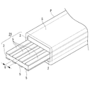
- FIG. 1 It is a perspective view of a core type which shows a 1st embodiment of the present invention.
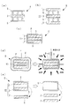
- the manufacturing method of the hollow structure which concerns on this invention is shown, (a) is a peeling member covering process, (b) is a core type assembly process, (c) is a prepreg lamination process, (d) is a forming process, (e ) Is a figure which each shows a core-mold extraction process.
- FIGS. 1 to 5 An embodiment of the present invention will be described with reference to FIGS. 1 to 5.
- FIG. 1 is a perspective view of a core mold 11 according to a first embodiment of the present invention.
- the core 11 is used to form a long hollow structure S such as a rotor blade of a helicopter with a prepreg P, for example.
- a vacuum bag V is covered as described later, and the inside of the vacuum bag V is heated and molded while vacuuming,
- the prepreg P is thermoset while being pressed against the outer peripheral surface of the core mold 11 to form a hollow structure S having a shape (shape along the shape) similar to the core mold 11, so-called autoclave molding.
- the core mold 11 is pulled out of the hollow structure S to complete the hollow structure S.
- the core mold 11 includes two outer mold members 2 (first mold members) extending in the longitudinal direction, and a middle mold member 3 (second mold member) sandwiched between the outer mold members 2. Have.
- the medium-sized member 3 can be extracted in the longitudinal direction from between the two outer-shaped members 2 after the hollow structure S is formed.
- a tape 5 (a peeling member) formed of a low friction material is attached.
- the tape 5 is attached to both sides of the middle member 3, but the tape 5 may be attached to the outer member 2 or may be attached to both the outer member 2 and the middle member 3. It is also good.
- the material of the tape 5 are, for example, fluorocarbon resin materials such as polytetrafluoroethylene (registered trademark: Teflon), but if it is excellent in releasability and heat resistance, for example, polypropylene, polyarete, diacetyl cellulose, tri It is also conceivable to use other materials such as acetyl cellulose, acetyl cellulose butyrate, silicone resin, alkit resin and the like. Furthermore, instead of using the adhesive tape 5 as a peeling member, a film made of the above-described materials or a film coated with the above-described materials or the like may be used.
- the tape 5 is stuck on both surfaces (joining surface) of the middle member 3 which comprises the core type
- mold 11 peeleling member covering process A).
- the tape 5 may be stuck to the mating surface of the outer mold member 2 instead of being stuck to both surfaces of the middle mold member 3.
- the core mold 11 is assembled by superposing the two outer mold members 2 on the middle mold member 3 with the tape 5 attached on both sides (core mold assembly process B). At this time, it is more preferable to apply a release agent between the tape 5 and the outer mold member 2.
- a prepreg P is laminated on the surface of the core mold 11 (prepreg lamination step C).
- the vacuum bag V is put on the core mold 11 on which the prepreg P is laminated, and then, as shown on the right side of FIG. 2 (d) The autoclave molding which heats heating while evacuating is performed (forming process D).
- the hollow structure S is completed.
- the core mold 11 is taken out of the vacuum bag V together with the hollow structural body S, and as shown on the left side of FIG. 2 (e), first, the middle mold member 3 of the core mold 11 is placed between the two outer mold members 2
- the two outer mold members 2 are pulled out of the hollow structure S as shown on the right side of FIG. 2 (e) after peeling off and pulling out in the longitudinal direction (core mold removing step E).
- core mold removing step E By first removing the middle mold member 3 from between the two outer mold members 2, the two outer mold members 2 can be easily pulled out of the hollow structure S thereafter. Thereby, the hollow structural body S is completed.
- the middle member 3 is very easy to remove. For this reason, while the workability at the time of extracting medium-sized member 3 is greatly improved, it prevents that the mating face of outer-shaped member 2 and medium-sized member 3 is damaged or worn out, and the durability of core 11 is improved. It can be dramatically improved.
- the tape 5 is easy to replace even if damaged, the condition of the core 11 can be kept healthy over a long period of time by replacing it regularly.
- the space between the outer mold member 2 and the middle mold member 3 is sealed in a liquid tight manner. .
- the resin material of the molten or softened prepreg P is cored by the pressure at the time of molding. This prevents the mold 11 from entering the dividing surface. For this reason, it is possible to prevent the thickness of the completed hollow structure S from being reduced or the accuracy from being reduced.
- FIG. 3 is a perspective view of a core 21 showing a second embodiment of the present invention.
- the tape 5 made of a low friction material is attached to both surfaces of the middle member 3 constituting the core die 21.
- a plurality of vacant spaces 6 extending along the longitudinal direction and provided along a longitudinal direction are provided between the plurality of tapes 5 in parallel.
- the other configuration is the same as that of the first embodiment.
- the width dimension of each of the plurality of tapes 5 is 10 mm, and the width dimension of the empty space 6 is also 10 mm.
- the number of the tapes 5 and the width dimensions of the tapes 5 and the vacant space 6 can be appropriately changed according to the dimensions of the hollow structure S. Further, the width dimensions of the tape 5 and the empty space 6 do not necessarily have to be the same.
- the tape 5 may be stuck to the joint surface of the outer mold member 2 instead of being stuck to both sides of the middle mold member 3.
- the tape 5 is an outer mold by attaching a plurality of tapes 5 with spaces between the middle mold member 3 on both surfaces (or the joint surface of the outer mold member 2) at intervals.
- the area in close contact with the member 2 (or medium-sized member 3) is significantly reduced. Therefore, it is possible to make the frictional resistance at the time of extracting the middle mold member 3 from between the outer mold members 2 smaller than in the case of the first embodiment, and to make it easier to pull out the middle mold member 3 from between the outer mold members 2 after the molding is completed. it can.
- the amount of use of the tape member 5 can be reduced to reduce the cost.
- FIG. 4 is a perspective view of a core mold 31 according to a third embodiment of the present invention.
- a plurality of tapes 5 formed of a low friction material are attached to both surfaces of the middle member 3 constituting the core mold 31.
- a plurality of resin bands 7 are attached to these vacant spaces 6 via a mold release agent.
- These resin bands 7 are made of a resin material similar to the prepreg P, and are formed in a band shape.
- the resin band 7 may not contain reinforcing fibers. It is preferable to set the thickness of the resin band 7 equal to the thickness of the tape 5.
- the width of the resin band 7 is set to be equal to or slightly smaller than the width of the empty space 6. The other configuration is the same as that of the second embodiment.
- a plurality of tapes 5 are attached to both surfaces of the middle-sized member 3 (or the joint surface of the outer-shaped member 2) at intervals, and a resin material similar to the prepreg P is used in the empty space 6 therebetween.
- the resin band 7 formed into a strip shape is attached via a release agent.
- the resin band 7 is sandwiched together with the tape 5 between the two outer mold members 2 and the middle mold member 3 (matching surfaces).
- the resin band 7 is softened by heat, and the softened resin material is the outer mold member 2 and the middle mold member 3. From the space (the mating surface), the pressure of the pressure causes the prepreg P forming the hollow structure S to expand and the resin material of the prepreg P is compensated.
- the resin material of the softened resin band 7 may be more positively bulged toward the prepreg P by making the resin band 7 thicker than the tape 5.
- the resin material that should originally form the prepreg P intrudes into the space between the outer mold member 2 and the middle mold member 3, and the thickness of the completed hollow structure S decreases. It is possible to prevent the accuracy from being reduced.
- the resin band 7 is interposed between the outer mold member 2 and the middle mold member 3 via a release agent. For this reason, similarly to the tape 5, the effect of facilitating the separation between the outer mold member 2 and the middle mold member 3 is achieved.
- FIG. 5 is a perspective view of a core mold 41 showing a fourth embodiment of the present invention.
- a resin band 8 made of a resin material similar to the prepreg P is sandwiched between the two outer mold members 2 and the middle mold member 3 constituting the core mold 41 via a release agent.
- the tape 5 of the first to third embodiments is not used.
- the width of the resin band 8 is set to be substantially the same as the width of the core mold 41 (the outer mold member 2 and the middle mold member 3).
- the respective mold members 2, 3 and Between the outer mold member 2 and the middle mold member 3 is easily peeled off by the mold release agent interposed between the resin band 8 and the middle mold member 3 from between the two outer mold members 2 after the formation of the hollow structure S. It becomes easy to take out.
- the resin band 8 is softened by heat, and the softened resin material is the outer mold member 2 and There is an effect of bulging toward the prepreg P forming the hollow structure S from between (the mating surface) with the middle-sized member 3 and compensating the resin material of the prepreg P. Thereby, it is possible to prevent the reduction of the thickness of the completed hollow structural body S and the deterioration of the quality such as the dimensional accuracy.
- the split core molds 11, 21, 31, 31 As described above, according to the method of manufacturing the core molds 11, 21, 31, 41 and the hollow structural body S according to the present invention, after the hollow structural body S is formed, the split core molds 11, 21, 31, 31
- the middle mold member 3 is easily extracted from between the outer mold members 2 of 41, and the durability of the core molds 11, 21, 31, 41 is enhanced, and a prepreg on the mating surface of the outer mold member 2 and the middle mold member 3 It is possible to prevent the resin of P from flowing backward to reduce the thickness of the hollow structure S, and to improve the quality such as dimensional accuracy.
- the present invention is not limited to only the configurations of the first to fourth embodiments described above, and various changes and modifications can be made as appropriate without departing from the scope of the present invention. Embodiments to which the present invention has been modified are also included in the scope of the present invention.
- the shape or split structure of the core mold 11, 21, 31, 41 (the outer mold member 2, the middle mold member 3), the shape of the hollow structure S, etc. are not limited to those of the above embodiment. . That is, although the core molds 11, 21, 31 and 41 in each of the above embodiments have the upper and lower three division structure in which one middle mold member 3 is sandwiched between the two outer mold members 2, It is also conceivable to use a two-division structure or three divisions on the left and right (two divisions on the left and right).
Landscapes
- Engineering & Computer Science (AREA)
- Mechanical Engineering (AREA)
- Chemical & Material Sciences (AREA)
- Composite Materials (AREA)
- Moulding By Coating Moulds (AREA)
- Casting Or Compression Moulding Of Plastics Or The Like (AREA)
- Moulds For Moulding Plastics Or The Like (AREA)
Priority Applications (2)
| Application Number | Priority Date | Filing Date | Title |
|---|---|---|---|
| EP14842876.6A EP2993021B1 (en) | 2013-09-05 | 2014-05-27 | Core box and method for producing hollow structure |
| US14/901,776 US10322529B2 (en) | 2013-09-05 | 2014-05-27 | Assembled mandrel and method for producing hollow structure |
Applications Claiming Priority (2)
| Application Number | Priority Date | Filing Date | Title |
|---|---|---|---|
| JP2013184359A JP6184808B2 (ja) | 2013-09-05 | 2013-09-05 | 中子型および中空構造体の製造方法 |
| JP2013-184359 | 2013-09-05 |
Publications (1)
| Publication Number | Publication Date |
|---|---|
| WO2015033625A1 true WO2015033625A1 (ja) | 2015-03-12 |
Family
ID=52628115
Family Applications (1)
| Application Number | Title | Priority Date | Filing Date |
|---|---|---|---|
| PCT/JP2014/063933 Ceased WO2015033625A1 (ja) | 2013-09-05 | 2014-05-27 | 中子型および中空構造体の製造方法 |
Country Status (4)
| Country | Link |
|---|---|
| US (1) | US10322529B2 (https=) |
| EP (1) | EP2993021B1 (https=) |
| JP (1) | JP6184808B2 (https=) |
| WO (1) | WO2015033625A1 (https=) |
Cited By (1)
| Publication number | Priority date | Publication date | Assignee | Title |
|---|---|---|---|---|
| CN115723354A (zh) * | 2022-11-22 | 2023-03-03 | 常州启赋安泰复合材料科技有限公司 | 一种复合材料方管楔形分块成型模具 |
Families Citing this family (3)
| Publication number | Priority date | Publication date | Assignee | Title |
|---|---|---|---|---|
| AU2017210021B2 (en) * | 2016-01-19 | 2019-07-11 | Sphereo Sound Ltd. | Synthesis of signals for immersive audio playback |
| CN111823614B (zh) * | 2020-07-14 | 2022-03-29 | 中车青岛四方机车车辆股份有限公司 | 一种复合材料多腔结构的成型方法 |
| US11660829B2 (en) * | 2021-02-09 | 2023-05-30 | Spirit Aerosystems, Inc. | Method of seamlessly bagging composite parts |
Citations (4)
| Publication number | Priority date | Publication date | Assignee | Title |
|---|---|---|---|---|
| JPS62207633A (ja) * | 1986-03-07 | 1987-09-12 | Hitachi Chem Co Ltd | Frp中空角材の製造法 |
| JP2011011474A (ja) * | 2009-07-02 | 2011-01-20 | Honda Motor Co Ltd | 長尺状成形物の成形方法 |
| JP2011011477A (ja) | 2009-07-02 | 2011-01-20 | Honda Motor Co Ltd | 中空構造用プリプレグ成形体の成形方法及び複合材成形品の成形方法 |
| US20130196087A1 (en) * | 2008-08-15 | 2013-08-01 | Sigma-Tek, Llc | Collapsible Mandrel Tools and Associated Methods for Fabrication of Wound Composite Articles |
Family Cites Families (8)
| Publication number | Priority date | Publication date | Assignee | Title |
|---|---|---|---|---|
| US4622091A (en) * | 1984-11-29 | 1986-11-11 | The Boeing Company | Resin film infusion process and apparatus |
| DE8616697U1 (de) | 1986-06-23 | 1986-08-07 | A-Z Formen- und Maschinenbau GmbH, 8000 München | Reifenvulkanisierform |
| JPS6341131A (ja) * | 1986-08-05 | 1988-02-22 | Hitachi Chem Co Ltd | Frp中空角材の製造法 |
| EP1561560A4 (en) * | 2002-10-30 | 2009-11-11 | Menicon Co Ltd | GAS FORM FOR CONTACT LENSES AND MANUFACTURING METHOD FOR CONTACT LENSES USING THE CASTING FORM |
| US7293737B2 (en) * | 2004-04-20 | 2007-11-13 | The Boeing Company | Co-cured stringers and associated mandrel and fabrication method |
| JP5096107B2 (ja) * | 2007-10-31 | 2012-12-12 | トヨタ自動車株式会社 | 樹脂構造体の製造方法 |
| DE102009002697B4 (de) * | 2009-04-28 | 2014-02-27 | Airbus Operations Gmbh | Formkern und Verfahren zur Herstellung eines Faserverbundbauteils für die Luft- und Raumfahrt |
| JP5416554B2 (ja) | 2009-11-06 | 2014-02-12 | 川崎重工業株式会社 | 複合材料構造物製造用治具 |
-
2013
- 2013-09-05 JP JP2013184359A patent/JP6184808B2/ja active Active
-
2014
- 2014-05-27 WO PCT/JP2014/063933 patent/WO2015033625A1/ja not_active Ceased
- 2014-05-27 EP EP14842876.6A patent/EP2993021B1/en not_active Not-in-force
- 2014-05-27 US US14/901,776 patent/US10322529B2/en active Active
Patent Citations (4)
| Publication number | Priority date | Publication date | Assignee | Title |
|---|---|---|---|---|
| JPS62207633A (ja) * | 1986-03-07 | 1987-09-12 | Hitachi Chem Co Ltd | Frp中空角材の製造法 |
| US20130196087A1 (en) * | 2008-08-15 | 2013-08-01 | Sigma-Tek, Llc | Collapsible Mandrel Tools and Associated Methods for Fabrication of Wound Composite Articles |
| JP2011011474A (ja) * | 2009-07-02 | 2011-01-20 | Honda Motor Co Ltd | 長尺状成形物の成形方法 |
| JP2011011477A (ja) | 2009-07-02 | 2011-01-20 | Honda Motor Co Ltd | 中空構造用プリプレグ成形体の成形方法及び複合材成形品の成形方法 |
Non-Patent Citations (1)
| Title |
|---|
| See also references of EP2993021A4 |
Cited By (1)
| Publication number | Priority date | Publication date | Assignee | Title |
|---|---|---|---|---|
| CN115723354A (zh) * | 2022-11-22 | 2023-03-03 | 常州启赋安泰复合材料科技有限公司 | 一种复合材料方管楔形分块成型模具 |
Also Published As
| Publication number | Publication date |
|---|---|
| EP2993021B1 (en) | 2017-07-26 |
| JP2015051538A (ja) | 2015-03-19 |
| US20170001338A1 (en) | 2017-01-05 |
| US10322529B2 (en) | 2019-06-18 |
| JP6184808B2 (ja) | 2017-08-23 |
| EP2993021A1 (en) | 2016-03-09 |
| EP2993021A4 (en) | 2016-04-20 |
Similar Documents
| Publication | Publication Date | Title |
|---|---|---|
| JP5430424B2 (ja) | 航空機翼構造の成形方法 | |
| JP4964961B2 (ja) | 熱可塑性複合材で形成されるパネルを製造する方法 | |
| JP5475465B2 (ja) | 航空機の胴体のための複合材料構造物およびその製造方法 | |
| WO2015033625A1 (ja) | 中子型および中空構造体の製造方法 | |
| JP2011235635A5 (https=) | ||
| US20150343715A1 (en) | Method for manufacturing carbon fiber panels stiffened with omega stringers | |
| JP2009221390A (ja) | 複合材連続成形用プリプレグピールプライ | |
| JPS61139426A (ja) | 複合材の製作方法 | |
| JP5315147B2 (ja) | 中空構造用プリプレグ成形体の成形方法及び複合材成形品の成形方法 | |
| EP2639034A1 (fr) | Procédé de réalisation d'une pièce en matériau composite et outillage pour sa mise en oeuvre | |
| KR20180053997A (ko) | 외피가 없는 언아이소그리드 복합재 구조물의 제조방법 | |
| WO2022099707A1 (zh) | 一种用于制作帽型增强构件的芯模 | |
| JP2010115822A (ja) | 断面の異なる複合材型材の連続成形方法 | |
| JP4648019B2 (ja) | 加圧バッグの製造方法、及び係る加圧バッグを用いた複合材成形品の成形方法 | |
| JP2010000655A (ja) | ハニカムサンドイッチパネルおよびその製造方法 | |
| US20160176121A1 (en) | Method of forming a laminar composite structure | |
| WO2021095207A1 (ja) | 治具 | |
| CN114506095A (zh) | 一种用于制作帽型增强构件的芯模 | |
| JP2015051538A5 (https=) | ||
| EP3007894B1 (fr) | Procédé d'obtention d'une cale pelable non plane et cale pelable non plane ainsi obtenue | |
| JP5325703B2 (ja) | ビード部材の製造方法及び製造装置 | |
| JP4801292B2 (ja) | 複合材中空部品の成形方法 | |
| CN102241143A (zh) | 复合材轮圈制法 | |
| EP2522495A1 (en) | Structural member with flange having a clean cut edge, and process for the manufacture thereof | |
| CN110225816A (zh) | 带有剥离层的成型构件 |
Legal Events
| Date | Code | Title | Description |
|---|---|---|---|
| 121 | Ep: the epo has been informed by wipo that ep was designated in this application |
Ref document number: 14842876 Country of ref document: EP Kind code of ref document: A1 |
|
| REEP | Request for entry into the european phase |
Ref document number: 2014842876 Country of ref document: EP |
|
| WWE | Wipo information: entry into national phase |
Ref document number: 2014842876 Country of ref document: EP |
|
| WWE | Wipo information: entry into national phase |
Ref document number: 14901776 Country of ref document: US |
|
| NENP | Non-entry into the national phase |
Ref country code: DE |