WO2015033432A1 - 逆止弁とその製造方法、その逆止弁を備えた送液装置及びその送液装置を備えた液体クロマトグラフ - Google Patents
逆止弁とその製造方法、その逆止弁を備えた送液装置及びその送液装置を備えた液体クロマトグラフ Download PDFInfo
- Publication number
- WO2015033432A1 WO2015033432A1 PCT/JP2013/074043 JP2013074043W WO2015033432A1 WO 2015033432 A1 WO2015033432 A1 WO 2015033432A1 JP 2013074043 W JP2013074043 W JP 2013074043W WO 2015033432 A1 WO2015033432 A1 WO 2015033432A1
- Authority
- WO
- WIPO (PCT)
- Prior art keywords
- radius
- slope
- sphere
- hole
- check valve
- Prior art date
- Legal status (The legal status is an assumption and is not a legal conclusion. Google has not performed a legal analysis and makes no representation as to the accuracy of the status listed.)
- Ceased
Links
Images


Classifications
-
- F—MECHANICAL ENGINEERING; LIGHTING; HEATING; WEAPONS; BLASTING
- F16—ENGINEERING ELEMENTS AND UNITS; GENERAL MEASURES FOR PRODUCING AND MAINTAINING EFFECTIVE FUNCTIONING OF MACHINES OR INSTALLATIONS; THERMAL INSULATION IN GENERAL
- F16K—VALVES; TAPS; COCKS; ACTUATING-FLOATS; DEVICES FOR VENTING OR AERATING
- F16K15/00—Check valves
- F16K15/02—Check valves with guided rigid valve members
- F16K15/04—Check valves with guided rigid valve members shaped as balls
-
- F—MECHANICAL ENGINEERING; LIGHTING; HEATING; WEAPONS; BLASTING
- F16—ENGINEERING ELEMENTS AND UNITS; GENERAL MEASURES FOR PRODUCING AND MAINTAINING EFFECTIVE FUNCTIONING OF MACHINES OR INSTALLATIONS; THERMAL INSULATION IN GENERAL
- F16K—VALVES; TAPS; COCKS; ACTUATING-FLOATS; DEVICES FOR VENTING OR AERATING
- F16K1/00—Lift valves or globe valves, i.e. cut-off apparatus with closure members having at least a component of their opening and closing motion perpendicular to the closing faces
- F16K1/32—Details
- F16K1/34—Cutting-off parts, e.g. valve members, seats
- F16K1/42—Valve seats
-
- F—MECHANICAL ENGINEERING; LIGHTING; HEATING; WEAPONS; BLASTING
- F16—ENGINEERING ELEMENTS AND UNITS; GENERAL MEASURES FOR PRODUCING AND MAINTAINING EFFECTIVE FUNCTIONING OF MACHINES OR INSTALLATIONS; THERMAL INSULATION IN GENERAL
- F16K—VALVES; TAPS; COCKS; ACTUATING-FLOATS; DEVICES FOR VENTING OR AERATING
- F16K25/00—Details relating to contact between valve members and seats
-
- G—PHYSICS
- G01—MEASURING; TESTING
- G01N—INVESTIGATING OR ANALYSING MATERIALS BY DETERMINING THEIR CHEMICAL OR PHYSICAL PROPERTIES
- G01N30/00—Investigating or analysing materials by separation into components using adsorption, absorption or similar phenomena or using ion-exchange, e.g. chromatography or field flow fractionation
- G01N30/02—Column chromatography
- G01N30/26—Conditioning of the fluid carrier; Flow patterns
- G01N30/28—Control of physical parameters of the fluid carrier
- G01N30/32—Control of physical parameters of the fluid carrier of pressure or speed
-
- G—PHYSICS
- G01—MEASURING; TESTING
- G01N—INVESTIGATING OR ANALYSING MATERIALS BY DETERMINING THEIR CHEMICAL OR PHYSICAL PROPERTIES
- G01N30/00—Investigating or analysing materials by separation into components using adsorption, absorption or similar phenomena or using ion-exchange, e.g. chromatography or field flow fractionation
- G01N30/02—Column chromatography
- G01N30/26—Conditioning of the fluid carrier; Flow patterns
- G01N30/28—Control of physical parameters of the fluid carrier
- G01N30/32—Control of physical parameters of the fluid carrier of pressure or speed
- G01N2030/326—Control of physical parameters of the fluid carrier of pressure or speed pumps
Definitions
- the present invention relates to a check valve that includes a sphere and a valve seat on which the sphere is seated to prevent back flow of the liquid, a method for manufacturing the check valve, a liquid feeding device that includes the check valve, and a liquid chromatograph that includes the liquid feeding device.
- the present invention relates to improvement of the internal structure of the check valve.
- liquid chromatographs sample components are identified according to the time required to pass through an analysis column, so that it is required to feed the mobile phase at a stable flow rate. Therefore, a plunger-type liquid feeding device is often used as a liquid feeding device that feeds the mobile phase.
- the plunger-type liquid feeding device has a plunger tip inserted into a pump chamber provided in the pump head, and the plunger and the cam mechanism reciprocate the plunger in one direction to change the volume in the pump chamber.
- the suction of the liquid into the pump chamber and the discharge of the liquid from the pump chamber are continuously performed.
- the pump head is provided with an inlet flow path for sucking liquid into the pump chamber and an outlet flow path for discharging liquid from the pump chamber.
- the liquid flows back and forth in each of the inlet flow path and the outlet flow path.
- a check valve is provided to prevent this.
- the check valve provided in the inlet channel and the outlet channel is generally composed of a sphere and a valve seat on which the sphere is seated.
- the valve seat is provided with an opening that forms a flow path through which liquid flows, and is seated so that a sphere contacts the edge of the opening to close the opening and stop the flow of fluid. .
- the check valve provided in the inlet channel is used to discharge the liquid from the pump chamber by opening the opening away from the valve seat by reducing the pressure in the pump chamber when sucking the liquid into the pump chamber.
- the check valve provided in the outlet channel reduces the pressure in the pump chamber when the liquid is sucked into the pump chamber, so that the sphere sits on the valve seat and closes the opening.
- the pump chamber is discharged, the sphere is separated from the valve seat and opens the opening.
- biting phenomenon in which the sphere is not separated when it should be separated from the valve seat.
- the biting phenomenon is likely to occur when the contact area between the sphere and the valve seat is large, the contact surface is smooth, and the surface pressure is high.
- the biting phenomenon occurs, the liquid feeding accuracy of the liquid feeding device is remarkably lowered, the liquid feeding at the set flow rate is not performed, and a normal analysis result cannot be obtained as a liquid chromatograph. It has been found that this biting phenomenon is likely to occur when the concave spherical surface portion where the sphere and the valve seat are in surface contact is mirror-finished.
- An object of the present invention is to further improve a check valve for linearly contacting a sphere and a valve seat, and to more reliably prevent the occurrence of a biting phenomenon between the sphere and the valve seat, thereby increasing the liquid feeding accuracy of the liquid feeding device. It is what.
- the check valve according to the present invention includes a sphere, a valve space that accommodates the sphere, and a through hole that forms a flow path for allowing liquid to flow into the valve space, and the sphere is formed so as to close the outlet opening of the through hole.
- a valve seat to be seated The valve seat has an annular shape inside the first slope so that an obtuse angled convex corner is formed in an annular shape at the boundary between the first slope and the first slope formed on the inner side surface of the through hole.
- a third inclined surface formed in an annular shape further inside the second inclined surface so as to form a convex corner in an annular shape at the boundary between the second inclined surface and the second inclined surface.
- the size of the sphere and the valve seat is set so that the sphere is in line contact with the convex corner of the boundary between the first slope and the second slope.
- At least one of the first slope, the second slope, and the third slope may be a concave curved surface. That is, the cross-sectional shapes of the first slope, the second slope, and the third slope do not have to be linear, and may be curved.
- the concave curved surface is, for example, a spherical surface coaxial with the through hole.
- a spherical surface can be formed with high accuracy by pressing a bearing steel ball having a spherical shape on the cutting portion against the edge portion of the through hole of the valve seat and processing the spherical surface.
- the first slope, the second slope, and the third slope are spherical surfaces having different curvature radii.
- the radius of curvature R 1 of the first inclined surface is larger than the radius R B of the sphere
- the radius of curvature R 2 of the second inclined surface is smaller than the radius R B of the large and spherical than the radius R H of the through hole
- the curvature radius R 3 of the third slope is formed larger than the radius R H of the through hole and smaller than the curvature radius R 2 of the second slope.
- the method for manufacturing the check valve includes the following steps (1) to (4). (1) forming a through-hole having a radius R H smaller than the radius R B of the sphere in the base material serving as a valve seat; (2) forming a first concave spherical surface having a radius of curvature R 1 larger than the radius R B of the sphere and coaxial with the through hole on the opening side of the through hole of the valve seat; (3) A second concave spherical surface having a radius of curvature R 2 larger than the radius R H of the through hole and smaller than the radius R B of the sphere and coaxial with the through hole is formed in the first concave spherical surface.
- Step (2) a bearing steel ball having a radius R 1 is used
- Step (3) a bearing steel ball having a radius R 2 is used
- Step (4) a bearing steel ball having a radius R 3 is used. be able to.
- the steel ball for bearing for forming the concave spherical surface it is possible to realize a spherical surface having a high sphericity as the first slope, the second slope, and the third slope.
- the roundness of the convex corner formed at the boundary between the first slope and the second slope, which is a part in line contact with the sphere, is determined by the sphericity of the first slope and the second slope.
- the first slope and the second slope can be spherical surfaces with high sphericity, the roundness of the convex corner portion is increased. Therefore, since the roundness of the portion that is in line contact with the sphere having a high sphericity is increased, the sealing performance when the sphere is seated on the valve seat is improved.
- the liquid delivery device according to the present invention includes the check valve of the present invention.
- a preferred embodiment of the liquid feeding device of the present invention includes a pump head having a pump chamber, an inlet portion for allowing the liquid to flow into the pump chamber, and an outlet portion for allowing the liquid to flow out of the pump chamber, and a plunger inserted from the tip into the pump chamber And a plunger driving section that reciprocates the plunger in one direction, and the check valve of the present invention is provided in each of the inlet section and the outlet section.
- the liquid chromatograph according to the present invention includes the liquid feeding device according to the present invention.
- a preferred embodiment of the liquid chromatograph of the present invention includes an analysis channel, a liquid feeding device for feeding a mobile phase to the analysis channel, a sample injection unit for injecting a sample into the analysis channel, and an analysis channel.
- An analysis column provided on the downstream side of the sample injection unit and separating the sample for each component; and a detector provided downstream of the analysis column and detecting the component separated by the analysis column, and a liquid feeding device The liquid feeding device of the present invention is used.
- the valve seat is formed in an annular shape on the inner side surface of the through hole in an annular shape, and an obtuse convex corner portion is formed in an annular shape at a boundary portion with the first inclined surface.
- a second slope formed in an annular shape is provided inside the first slope, and when the sphere is seated on the valve seat, the sphere is lined at the convex corner of the boundary between the first slope and the second slope. Since it is configured to contact, the biting between the sphere and the valve seat is prevented, and the valve is smoothly opened when the liquid flows in the forward direction.
- the convex corner at the boundary between the first slope and the second slope is sharp, the convex corner may be chipped or the surface of the sphere may be damaged.
- the angle that intersects one slope cannot be made too small. For this reason, the gap between the sphere and the second slope cannot be increased. Since the gap between the sphere and the second inclined surface is small, impurities in the fluid may accumulate in the gap and the contact between the sphere and the valve seat may be in a surface contact state.
- the check valve of the present invention includes a third slope formed in an annular shape further inside the second slope so as to form a convex corner at the boundary with the second slope. Yes. Accordingly, even when the angle at which the second inclined surface intersects the first inclined surface is not reduced, the gap between the sphere and the valve seat when the sphere is seated on the valve seat is widened, and the gap between the sphere and the valve seat is increased. Accumulation of impurities and the like in the fluid can be suppressed. As a result, the line contact state between the sphere and the valve seat is maintained, and the occurrence of the biting phenomenon between the sphere and the valve seat is prevented.
- the liquid feeding device includes the check valve of the present invention, biting between the sphere and the valve seat does not occur, and high liquid feeding accuracy can be realized.
- the liquid chromatograph according to the present invention includes the liquid feeding device of the present invention that realizes high liquid feeding accuracy, high analysis accuracy can be obtained.
- FIG. 6 is a process cross-sectional view illustrating the continuation of FIG. 5. It is sectional drawing which shows one Example of a liquid feeding apparatus. It is a channel lineblock diagram showing roughly one example of a liquid chromatograph.
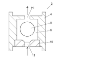
- the check valve 2 includes a casing 4, a sphere 8 and a valve seat 10.
- a valve space 6 is provided inside the casing 4, and a sphere 8 is movably accommodated in the valve space 6.
- the valve seat 10 is for seating the sphere 8 and is mounted on the casing 4.
- the valve seat 10 is provided with a through hole 12 that forms a liquid inlet, and the sphere 8 is seated on the edge of the through 12 to close the through hole 12, thereby closing the valve.
- a fluid outlet 14 is provided on the wall of the casing 4 on the side opposite to the valve seat 10.
- the sphere 8 is made of ruby, for example, and has a diameter of about 1.5 mm.
- the valve seat 10 is a member made of, for example, sapphire and having a cylindrical shape with an outer diameter of about 3 mm and a thickness of about 1 mm.
- the inner diameter of the through hole 12 is, for example, about 1 mm (radius RH is about 0.5 mm).
- valve seat 10 will be described with reference to FIGS. 2A, 2B, 2C, and 3.
- FIG. 2A, 2B, 2C, and 3
- a through hole 12 is provided in the center of the valve seat 10.
- An arc-shaped first slope 16, second slope 18, and third slope 20 are provided in this order from the outside at the edge of the spherical body 8 side opening of the through hole 12.
- the first inclined surface 16, the second inclined surface 18 and the third inclined surface 20 are concave spherical surfaces which are coaxial with the through hole 12.
- the first slope 16, the second slope 18 and the third slope 20 have different radii of curvature, the second slope 18 is provided continuously inside the first slope 16, and the third slope 20 is the second slope 18. It is continuously provided inside.
- a convex corner portion 17 is formed in an annular shape at a boundary portion between the first slope 16 and the second slope 18, and a convex corner portion 19 is formed at a boundary portion between the second slope 18 and the third slope 20. It is formed in an annular shape.
- the radius of curvature of the first slope 16 is R 1
- the radius of curvature of the second slope 18 is R 2
- the radius of curvature of the third slope 20 is R 3
- the radius of the sphere 8 is R B.
- the radius of the through hole 12 when the R H, R 1> R B > R 2> R 3> relation R H is established.
- the sphere 8 and the valve seat 10 are in line contact at the convex corner portion 17. Since the contact between the sphere 8 and the valve seat 10 is a line contact at the convex corner 17, the occurrence of the biting phenomenon between the sphere 8 and the valve seat 10 is prevented.
- the gap between the sphere 8 and the third inclined surface 20 is wider than the gap between the sphere 8 and the second slope 20.
- a wide gap is secured on the inner side of the convex corner 17 which is a line contact portion between the sphere 8 and the valve seat 10.
- the radius of curvature R 2 of the second slope 18 is further reduced, for example, to widen the gap between the sphere 8 and the second slope 18, thereby introducing impurities into the gap. It is also conceivable to prevent the accumulation of slag. However, if it does so, the convex corner 17 in line contact with the sphere 8 will be sharpened, and the surface of the sphere 8 may be scratched or the convex corner 17 may be missing.
- the angle formed by the convex corner portion 17 is preferably 155 ° or more.
- the angle formed by the convex corner portion 19 that does not contact the sphere 8 may be any angle as long as it can form a gap that does not cause accumulation of impurities or the like.
- the first inclined surface 16, the second inclined surface 18, and the third inclined surface 20 are concave spherical surfaces, which are selected from the ease of high-precision machining in the manufacturing stage. That is, since the concave spherical surface processing can easily control the center accuracy, it is easy to form the first slope 16, the second slope 18, and the third slope 20.
- the first inclined surface 16, the second inclined surface 18, and the third inclined surface 20 do not necessarily need to be concave spherical surfaces.
- the first slope 16 and the second slope 18 may be concave spherical surfaces
- the third slope 20 may be a tapered surface having a non-curved cross section.
- the first inclined surface 16, the second inclined surface 18, and the third inclined surface 20 may all be tapered surfaces having a non-curved cross-sectional shape.
- the non-curved tapered surface of the cross-sectional shape can be formed by pressing a conical drill tooth.
- valve seat 10 described with reference to FIGS. 2A, 2B, 2C, and 3 will be described in the order of steps with reference to FIGS.
- a through-hole 12 having a diameter R H (for example, 0.5 mm) is formed in the center of the disk-shaped base material to be the valve seat 10 in the thickness direction of the disk by known machining (FIGS. 5A and 5B). )).
- the bearing steel ball 22 having a radius R 1 is pressed against the opening of the through hole 12 of the valve seat 10 while rotating it (FIG. 5C), thereby forming an annular concave spherical surface on the edge of the through hole 12.
- One slope 16 is formed (FIG. 5D).
- the radius R 1 of the bearing steel ball 22 only needs to be larger than the radius R B (for example, 0.75 mm) of the sphere 8, and there is no particular limitation on the upper limit. However, it is necessary to make the depth so that a second slope 18 and a third slope 20 described later can be further formed inside the first slope 16, and the casing 4 is fixed to the outer periphery of the valve seat 10.
- R 1 is suitably 2.0 to 5.0 mm.
- the JIS standard defines bearing steel balls having different sizes in 0.5 mm increments within this range, and it is possible to form a concave spherical surface using bearing steel balls having a high degree of sphericity.
- the bearing steel ball 24 having a radius R 2 is pressed against the opening of the through hole 12 of the valve seat 10 in which the first slope 16 is formed (FIG. 6 (E)).
- a second slope 18 that is an annular concave spherical surface is formed inside 16 (FIG. 6F). Since the radius R 2 of the bearing steel ball 24 is smaller than the radius R 1 of the bearing steel ball 22, the roundness at the boundary between the first slope 16 and the second slope 18 is different due to the difference between R 1 and R 2.
- An annular convex corner 17 having a high height is formed.
- the bearing steel ball 26 having a radius R 3 is pressed against the opening of the through hole 12 of the valve seat 10 in which the second slope 18 is formed (FIG. 6 (G)), whereby the second slope 18 A third inclined surface 20 that is an annular concave spherical surface is formed on the inner side (FIG. 6H). Since the radius R 3 of the bearing steel ball 26 is smaller than the radius R 2 of the bearing steel ball 24, a convex corner is formed at the boundary between the second slope 18 and the third slope 20 due to the difference between R 2 and R 3. 19 is formed.
- the size of the second slope 18 remaining on the outside of the third slope 20 (the distance between the convex corner 17 and the convex corner 19) is 0.026 mm or less. It is preferable to process. Since the gap between the sphere 8 and the second inclined surface 18 is narrow, if the second inclined surface 18 remains large, impurities and the like accumulate between the sphere 8 and the second inclined surface 18, and the sphere 8 and the valve seat 10. This is because contact with can be surface contact.
- the liquid feeding device 30 reciprocates a plunger 36 in one direction (left and right in the drawing) in a pump chamber 34 provided inside a pump head 32, and sucks liquid into the pump chamber 34 and the pump chamber 34.
- the liquid is fed by continuously discharging the liquid from the tank.
- An eccentric cam 44 that rotates about a shaft 46 is disposed on the base end side (right side in the drawing) of the pump head 32.
- a cross head 40 is movably attached to the base end portion of the pump head 32.
- the cross head 40 holds the proximal end portion of the plunger 36 and includes a cam follower 42 on the opposite side of the plunger 36.
- a spring 48 (for example, a coil spring) that biases the cross head 40 toward the eccentric cam 44 is disposed inside the pump head 32.
- the cam follower 42 always follows the circumferential surface of the eccentric cam 44, and the cross head 40 reciprocates in one direction (left and right in the figure) by the rotation of the eccentric cam 44.
- the tip of the plunger 36 is inserted into the pump chamber 34. Since the plunger 36 is held by the cross head 40, it reciprocates in one direction together with the cross head 40 by the rotation of the eccentric cam 44.
- a ring-shaped sealing member 38 is provided at a portion of the pump chamber 34 where the plunger 36 is inserted.
- the seal member 38 is fixed to the pump head 32. The seal member 38 holds the outer peripheral surface of the plunger 36 and prevents liquid leakage from the pump chamber 32 to the crosshead 40 side.
- Check valves 2 a and 2 b are attached to the pump head 32.
- the check valve 2 a is attached to an inlet for allowing liquid to flow into the pump chamber 34
- the check valve 2 b is attached to an outlet for allowing liquid to flow out of the pump chamber 34.
- the check valves 2a and 2b the check valve 2 described in the above embodiment is used.
- the check valve 2a is connected to a flow path that leads to a container that stores the liquid to be sent, and the check valve 2b is a flow path that sends the liquid (for example, a liquid chromatograph). Are connected.
- a liquid feeding device 30, a sample injection unit 54, an analysis column 56, and a detector 58 are provided on the analysis flow path 50.
- the liquid feeding device 30 is the liquid feeding device shown in FIG.
- the liquid feeding device 30 sends the mobile phase contained in the mobile phase container 52 through the analysis flow path 50.
- a sample injection unit 54 is provided on the downstream side of the liquid feeding device 30.
- the sample injection unit 54 is an autosampler that automatically collects a sample and injects it into the analysis flow path 50.
- An analysis column 56 for separating the sample for each component is provided on the downstream side of the sample injection unit 54.
- a detector 58 for detecting components separated by the analysis column 56 is provided further downstream of the analysis column 56.
- the sample injected into the analysis channel 50 by the sample injection unit 54 flows downstream in the analysis channel 50 together with the mobile phase fed by the liquid feeding device 30 and is introduced into the analysis column 56.
- the components in the sample introduced into the analysis column 56 are separated by the difference in mobility in the analysis column 56, and are introduced into the detector 58 in order from components having the highest mobility and detected. By analyzing the detection signal obtained by the detector 58, the components in the sample are identified and quantified.
Landscapes
- Engineering & Computer Science (AREA)
- General Engineering & Computer Science (AREA)
- Mechanical Engineering (AREA)
- Physics & Mathematics (AREA)
- Health & Medical Sciences (AREA)
- Life Sciences & Earth Sciences (AREA)
- Chemical & Material Sciences (AREA)
- Analytical Chemistry (AREA)
- Biochemistry (AREA)
- General Health & Medical Sciences (AREA)
- General Physics & Mathematics (AREA)
- Immunology (AREA)
- Pathology (AREA)
- Check Valves (AREA)
Abstract
逆止弁は、球体と、球体を収容する弁空間と、弁空間に液を流入させる流路をなす貫通孔を内側に備え、貫通孔の出口開口部を塞ぐように球体を着座させる弁座と、を備えている。弁座は、貫通孔の内側側面に円環状に形成された第1斜面、第1斜面との境界部分に鈍角の凸状角部を円環状に形成するように第1斜面の内側に円環状に形成された第2斜面、及び第2斜面との境界部分に凸状角部を円環状に形成するように第2斜面のさらに内側に円環状に形成された第3斜面を備えている。球体と弁座の大きさは、第1斜面と第2斜面との境界部分の凸状角部に球体が線接触するように設定されている。
Description
本発明は、球体とその球体を着座させる弁座を備えて液の逆流を防止する逆止弁とその製造方法、その逆止弁を備えた送液装置及びその送液装置を備えた液体クロマトグラフに関し、特に、逆止弁の内部構造の改良に関するものである。
液体クロマトグラフでは、分析カラムを通過する時間によって試料成分の同定を行なうため、移動相を安定した流量で送液することが求められる。そのため、移動相を送液する送液装置にはプランジャ方式の送液装置が使用されることが多い。
プランジャ方式の送液装置は、ポンプヘッド内に設けられたポンプ室にプランジャの先端部が挿入されており、モータとカム機構によってプランジャを一方向に往復動させることでポンプ室内の容積を変化させ、ポンプ室への液の吸入とポンプ室からの液の吐出を連続的に行なうものである。
ポンプヘッドには、ポンプ室への液の吸入を行なう入口流路と、ポンプ室からの液の吐出を行なう出口流路が設けられており、入口流路と出口流路のそれぞれに液の逆流を防止する逆止弁が設けられている。入口流路や出口流路に設けられている逆止弁は、球体とその球体を着座させる弁座からなるものが一般的である。弁座には液を流通させる流路をなす開口部が設けられており、その開口部の縁に球体が当接するように着座させて開口部を塞ぎ、流体の流れを止めるようになっている。
入口流路に設けられた逆止弁は、ポンプ室へ液を吸入する際にポンプ室内が減圧されることで、球体が弁座から離れて開口部を開き、ポンプ室から液を吐出する際にポンプ室内が加圧されることで、球体が弁座に着座して開口部を塞ぐ。逆に、出口流路に設けられた逆止弁は、ポンプ室へ液を吸入する際にポンプ室内が減圧されることで、球体が弁座に着座して開口部を塞ぎ、ポンプ室から液を吐出する際にポンプ室内が加圧されることで、球体が弁座から離れて開口部を開く。これらの逆止弁により、入口流路からポンプ室へ液を吸入する際には、出口流路からポンプ室への液の逆流が防止され、ポンプ室から出口流路へ液を吐出する際には、ポンプ室から入口流路への液の逆流が防止される。
近年、液体クロマトグラフの分野では、数十nL/min~数μL/minという微小流量での分析の需要が高まっており、送液装置の送液精度の向上が望まれている。送液装置が所望流量での送液精度を向上させるためには、送液装置に設けられている逆止弁のシール性を確保する必要がある。そのため、従来は、弁座の開口部の縁に球体の球面と接触する径をもつ凹球面加工が施され、その円環状の凹球面部分において球体と弁座が面接触するようにし、さらに、その円環状の凹球面部分に鏡面加工が施されていた。これにより、球体と弁座との密着性を向上させ、液の逆流を防止するためのシール性を確保していた。
送液装置の送液精度の向上には、逆止弁が液の逆流を確実に防止するだけでなく、逆止弁が液の順方向への流れを阻害しないことも重要である。逆止弁が液の順方向への流れを阻害する原因として、球体が弁座から離れるべきときに離れなくなる所謂「食い付き現象」がある。食い付き現象は、球体と弁座との接触面積が広く、接触面が滑らかで、かつ面圧の高い場合に生じやすい。食い付き現象が生じると、送液装置の送液精度が著しく低下し、設定された流量での送液がなされなくなり、液体クロマトグラフとして正常な分析結果が得られなくなる。この食い付き現象は、球体と弁座が面接触する凹球面部分に鏡面加工が施されていると発生しやすいことがわかっている。
食い付き現象の発生を防止するために、弁座の開口部の縁に加工を施すことで、球体と弁座とを線接触させるようにすることが提案されている(特許文献1参照。)。球体と弁座とを線接触させるようにすることで、球体と弁座の食い付き現象の発生を防止し、送液精度の向上を図ることが可能である。
本発明は、球体と弁座とを線接触させる逆止弁をさらに改良し、球体と弁座の食い付き現象の発生をより確実に防止して送液装置の送液精度を高めることを目的とするものである。
本発明にかかる逆止弁は、球体と、球体を収容する弁空間と、弁空間に液を流入させる流路をなす貫通孔を内側に備え、貫通孔の出口開口部を塞ぐように球体を着座させる弁座と、を備えている。弁座は、貫通孔の内側側面に円環状に形成された第1斜面、第1斜面との境界部分に鈍角の凸状角部を円環状に形成するように第1斜面の内側に円環状に形成された第2斜面、及び第2斜面との境界部分に凸状角部を円環状に形成するように第2斜面のさらに内側に円環状に形成された第3斜面を備えている。球体と弁座の大きさは、第1斜面と第2斜面との境界部分の凸状角部に球体が線接触するように設定されている。
上記逆止弁において、第1斜面、第2斜面及び第3斜面のうち少なくとも一つが凹曲面であってもよい。すなわち、第1斜面、第2斜面及び第3斜面の断面形状は、直線形状である必要はなく、湾曲していてもよい。
凹曲面とは、例えば貫通孔と同軸の球面である。かかる球面は、切削部分が球面形状となっているベアリング用鋼球を弁座の貫通孔の縁部分に押し当てて球面加工することにより高精度に形成することができる。
好ましい実施態様では、第1斜面、第2斜面及び第3斜面がそれぞれ互いに曲率半径の異なる球面となっている。
上記の場合、第1斜面の曲率半径R1は球体の半径RBよりも大きく、第2斜面の曲率半径R2は貫通孔の半径RHよりも大きくかつ球体の半径RBよりも小さく、第3斜面の曲率半径R3は貫通孔の半径RHよりも大きくかつ第2斜面の曲率半径R2よりも小さく形成されている。
上記逆止弁を製造する方法は、以下のステップ(1)~(4)を備えている。
(1)弁座となる基材に球体の半径RBよりも小さい半径RHを有する貫通孔を形成するステップ、
(2)弁座の貫通孔の開口部側に、球体の半径RBよりも大きい曲率半径R1を有しかつ貫通孔と同軸である第1の凹球面を形成するステップ、
(3)第1の凹球面内に、貫通孔の半径RHよりも大きく球体の半径RBよりも小さい曲率半径R2を有しかつ貫通孔と同軸である第2の凹球面を形成するステップ、及び
(4)第2の凹球面内に、貫通孔の半径RHよりも大きく第2の凹球面の曲率半径R2よりも小さい曲率半径R3を有しかつ貫通孔と同軸である第3の凹球面を形成するステップ。
(1)弁座となる基材に球体の半径RBよりも小さい半径RHを有する貫通孔を形成するステップ、
(2)弁座の貫通孔の開口部側に、球体の半径RBよりも大きい曲率半径R1を有しかつ貫通孔と同軸である第1の凹球面を形成するステップ、
(3)第1の凹球面内に、貫通孔の半径RHよりも大きく球体の半径RBよりも小さい曲率半径R2を有しかつ貫通孔と同軸である第2の凹球面を形成するステップ、及び
(4)第2の凹球面内に、貫通孔の半径RHよりも大きく第2の凹球面の曲率半径R2よりも小さい曲率半径R3を有しかつ貫通孔と同軸である第3の凹球面を形成するステップ。
ステップ(2)では半径R1のベアリング用鋼球を使用し、ステップ(3)では半径R2のベアリング用鋼球を使用し、ステップ(4)では半径R3のベアリング用鋼球を使用することができる。凹球面の形成にベアリング用鋼球を用いることで、第1斜面、第2斜面及び第3斜面として真球度の高い球面を実現することができる。球体と線接触する部分である第1斜面と第2斜面との境界部分に形成される凸状角部の真円度は第1斜面と第2斜面の真球度によって決定される。第1斜面及び第2斜面が真球度の高い球面にすることができるので、凸状角部の真円度が高くなる。したがって、真球度の高い球体に線接触させる部分の真円度が高くなるので、球体を弁座に着座させたときのシール性が高くなる。
本発明にかかる送液装置は、本発明の逆止弁を備えているものである。
本発明の送液装置の好ましい実施態様は、ポンプ室、ポンプ室に液を流入させる入口部及びポンプ室から液を流出させる出口部を備えたポンプヘッドと、ポンプ室に先端から挿入されたプランジャと、プランジャを一方向へ往復動させるプランジャ駆動部と、を備え、本発明の逆止弁が入口部及び出口部のそれぞれに設けられているものである。
本発明にかかる液体クロマトグラフは、本発明の送液装置を備えているものである。
本発明の液体クロマトグラフの好ましい実施態様は、分析流路と、分析流路に移動相を送液する送液装置と、分析流路中に試料を注入する試料注入部と、分析流路上で試料注入部よりも下流側に設けられ、試料を成分ごとに分離する分析カラムと、分析カラムの下流に設けられ、分析カラムで分離された成分を検出する検出器と、を備え、送液装置として本発明の送液装置を用いたものである。
本発明の逆止弁は、弁座が、貫通孔の内側側面に円環状に形成された第1斜面、第1斜面との境界部分に鈍角の凸状角部を円環状に形成するように第1斜面の内側に円環状に形成された第2斜面を備えており、球体が弁座に着座する際は、第1斜面と第2斜面との境界部分の凸状角部に球体が線接触するように構成されているので、球体と弁座との食い付きが防止され、液を順方向へ流す際の弁の開放が円滑に行なわれる。
ところで、第1斜面と第2斜面との境界部分の凸状角部が尖っていると、凸状角部が欠けたり球体の表面に傷が付いたりするおそれがあるため、第2斜面が第1斜面と交わる角度をあまり小さくすることはできない。そのため、球体と第2斜面との間の隙間を大きくすることができない。球体と第2斜面との間の隙間が小さいため、流体中の不純物などがこの隙間に堆積し、球体と弁座の接触が面接触状態となってしまうおそれがある。
そこで、本発明の逆止弁においては、第2斜面との境界部分に凸状角部を円環状に形成するように第2斜面のさらに内側に円環状に形成された第3斜面を備えている。これにより、第2斜面が第1斜面と交わる角度を小さくしなくても、球体が弁座に着座したときの球体と弁座との間の隙間が広くなり、球体と弁座との隙間への流体中の不純物などの堆積を抑制することができる。その結果、球体と弁座との線接触状態が維持され、球体と弁座の食い付き現象の発生が防止される。
本発明にかかる送液装置は本発明の逆止弁を備えているので、球体と弁座との食い付きが発生せず、高い送液精度を実現することができる。
本発明にかかる液体クロマトグラフは、高い送液精度を実現する本発明の送液装置を備えているので、高い分析精度を得ることができる。
図1を用いて逆止弁の一実施例について説明する。
逆止弁2は、ケーシング4、球体8及び弁座10により構成されている。ケーシング4の内部に弁空間6が設けられており、その弁空間6内に球体8が移動可能に収容されている。弁座10は球体8を着座させるためのものであり、ケーシング4に装着されている。弁座10には液流入口をなす貫通孔12が設けられており、球体8がその貫通12の縁に着座して貫通孔12を塞ぐことで、弁を閉じるようになっている。ケーシング4を構成する壁面には、弁座10とは反対側に流体出口14が設けられている。
球体8は、例えばルビーからなり、直径が約1.5mmである。弁座10は、例えばサファイアからなり、外径の直径が約3mm、厚みが約1mmの円柱形状を有する部材である。貫通孔12の内径は例えば約1mm(半径RHは約0.5mm)である。
弁座10について図2A、図2B、図2C及び図3を用いて説明する。
弁座10の中心に貫通孔12が設けられている。貫通孔12の球体8側開口部の縁に、円弧状の第1斜面16、第2斜面18及び第3斜面20が外側から順に設けられている。第1斜面16、第2斜面18及び第3斜面20は貫通孔12と同軸の凹球面である。第1斜面16、第2斜面18及び第3斜面20は互いに異なる曲率半径をもち、第2斜面18は第1斜面16の内側に連続して設けられ、第3斜面20は第2斜面18の内側に連続して設けられている。
第1斜面16と第2斜面18との間の境界部分に凸状角部17が円環状に形成され、第2斜面18と第3斜面20との間の境界部分に凸状角部19が円環状に形成されている。図3に示されているように、第1斜面16の曲率半径をR1、第2斜面18の曲率半径をR2、第3斜面20の曲率半径をR3、球体8の半径をRB、貫通孔12の半径をRHとすると、R1>RB>R2>R3>RHの関係が成立する。これにより、球体8が弁座10に着座する際は、球体8と弁座10は凸状角部17において線接触する。球体8と弁座10との接触が凸状角部17における線接触であるため、球体8と弁座10の食い付き現象の発生が防止される。
第2斜面18のさらに内側に形成された第3斜面20は、第2斜面18の曲率半径R2よりもさらに小さい曲率半径R3をもっているため、球体8と第3斜面20との間の隙間は球体8と第2斜面20との間の隙間よりも広くなる。これにより、球体8と弁座10との線接触部分である凸状角部17よりも内側に広い隙間が確保される。この部分に広い隙間が確保されることで、球体8と弁座10との間の隙間部分に不純物などが堆積することが防止され、球体8と弁座10との面接触化による食い付き現象の発生が防止される。
ここで、第3斜面20を形成せずに、第2斜面18の曲率半径R2をさらに小さくするなどして球体8と第2斜面18との間の隙間を広げることでその隙間への不純物の堆積を防止することも考えられる。しかし、そうすると、球体8と線接触する凸状角部17が尖ってしまい、球体8の表面に傷を付けたり凸状角部17が欠けてしまったりするおそれが生じる。
上記理由により、凸状角部17がなす角度は155°以上であることが好ましい。これに対し、球体8と接触しない凸状角部19がなす角度は、不純物などの堆積が起こらない程度の隙間を形成することのできる角度であればいかなる角度であってもよい。
ところで、第1斜面16、第2斜面18及び第3斜面20は凹球面となっているが、これは、製造段階における高精度加工の容易さから選択されたものである。すなわち、凹球面加工は中心精度の制御が容易であるため、第1斜面16、第2斜面18及び第3斜面20を形成することが容易である。
第1斜面16、第2斜面18及び第3斜面20は必ずしも凹球面である必要はない。例えば、図4Aに示されているように、第1斜面16と第2斜面18が凹球面、第3斜面20が断面形状の湾曲していないテーパ面であってもよいし、図4Bに示されているように、第1斜面16、第2斜面18及び第3斜面20がすべて断面形状の湾曲していないテーパ面であってもよい。断面形状の湾曲していないテーパ面は、円錐形状のドリル歯を押し当てることで形成することができる。
次に、図2A、図2B、図2C及び図3を用いて説明した弁座10の製造方法を図5及び図6を用いて工程順に説明する。
弁座10となる円盤形状の基材の中心部に、周知の機械加工により円盤の厚み方向に直径RH(例えば0.5mm)の貫通孔12を形成する(図5(A)及び(B))。
弁座10の貫通孔12の開口部に半径R1のベアリング用鋼球22を回転させながら押し当てることにより(図5(C))、貫通孔12の縁に円環状の凹球面である第1斜面16を形成する(図5(D))。ベアリング用鋼球22の半径R1は球体8の半径RB(例えば0.75mm)よりも大きければよく、上限については特に制限はない。しかし、第1斜面16の内側にさらに後述の第2斜面18及び第3斜面20を形成することができる程度の深さにする必要があること、弁座10の外周部にケーシング4で固定するための平面を残しておく必要があることから、R1は2.0~5.0mmが適当である。JIS規格では、この範囲において0.5mm刻みで大きさの異なるベアリング用鋼球が規定されており、真球度の等級が高いベアリング用鋼球を用いた凹球面の形成が可能である。
次に、第1斜面16が形成された弁座10の貫通孔12の開口部に半径R2のベアリング用鋼球24を回転させながら押し当てることにより(図6(E))、第1斜面16の内側に円環状の凹球面である第2斜面18を形成する(図6(F))。ベアリング用鋼球24の半径R2はベアリング用鋼球22の半径R1よりも小さいため、R1とR2の違いにより、第1斜面16と第2斜面18との境界部分に真円度の高い円環状の凸状角部17が形成される。
さらに、第2斜面18が形成された弁座10の貫通孔12の開口部に半径R3のベアリング鋼球26を回転させながら押し当てることにより(図6(G))、第2斜面18の内側に円環状の凹球面である第3斜面20を形成する(図6(H))。ベアリング鋼球26の半径R3はベアリング用鋼球24の半径R2よりも小さいため、R2とR3の違いにより、第2斜面18と第3斜面20との境界部分に凸状角部19が形成される。
第3斜面20の形成においては、第3斜面20の外側に残る第2斜面18の大きさ(凸状角部17と凸状角部19の間の距離)が0.026mm以下になるように加工することが好ましい。球体8と第2斜面18との間の隙間は狭いため、第2斜面18が大きく残っていると、球体8と第2斜面18との間に不純物などが堆積し、球体8と弁座10との接触が面接触となりうるからである。
次に、以上において説明した逆止弁2を備えた送液装置の一実施例について、図7を用いて説明する。
この送液装置30は、ポンプヘッド32の内部に設けられたポンプ室34において、プランジャ36を一方向(図において左右方向)へ往復動させ、ポンプ室34内への液の吸入とポンプ室34からの液の吐出を連続的に行なうことにより送液を行なうものである。
ポンプヘッド32の基端側(図において右側)に、軸46を中心に回転する偏心カム44が配置されている。ポンプヘッド32の基端部にクロスヘッド40が移動可能に装着されている。クロスヘッド40はプランジャ36の基端部を保持し、プランジャ36とは反対側にカムフォロア42を備えている。ポンプヘッド32の内部に、クロスヘッド40を偏心カム44側へ付勢するバネ48(例えばコイルバネ)が配置されている。これにより、カムフォロア42は常時偏心カム44の周面に追従し、偏心カム44の回転によってクロスヘッド40が一方向(図において左右方向)へ往復動する。
プランジャ36の先端はポンプ室34内に挿入されている。プランジャ36はクロスヘッド40によって保持されているため、偏心カム44の回転によってクロスヘッド40とともに一方向へ往復動する。ポンプ室34のプランジャ36が挿入される部分にリング状のシール部材38が設けられている。シール部材38はポンプヘッド32に固定されている。シール部材38はプランジャ36の外周面を保持し、ポンプ室32からクロスヘッド40側への液漏れを防止している。
ポンプヘッド32に逆止弁2a及び2bが取り付けられている。逆止弁2aはポンプ室34へ液を流入させる入口部に取り付けられ、逆止弁2bはポンプ室34から液を流出させる出口部に取り付けられている。逆止弁2a及び2bとして上記実施例で説明した逆止弁2が用いられている。
図示は省略されているが、逆止弁2aには送液対象の液を貯留した容器に通じる流路が接続され、逆止弁2bには液を送液する流路(例えば、液体クロマトグラフの分析流路)が接続されている。
プランジャ36がポンプヘッド32の基端側(図において右側)へ移動すると、ポンプ室34内が減圧されることによって逆止弁2aの球体8aが弁座10aから離脱し、液がポンプ室34内に吸入される。このとき、逆止弁2bでは、球体8bが弁座10bに着座し、ポンプ室34側への液の逆流が防止される。逆に、プランジャ36がポンプヘッド32の先端側(図において左側)へ移動すると、ポンプ室34内が加圧されることによって、逆止弁2bの球体8bが弁座10bから離脱し、ポンプ室34からの送液が行なわれる。このとき、逆止弁2aでは、球体8aが弁座10aに着座し、ポンプ室34からの液の逆流が防止される。
次に、図7の送液装置を備えた液体クロマトグラフの一実施例について図8を用いて説明する。
分析流路50上に送液装置30、試料注入部54、分析カラム56及び検出器58が設けられている。送液装置30は図7に示した送液装置である。送液装置30は移動相容器52に収容された移動相を分析流路50で送液する。送液装置30の下流側に試料注入部54が設けられている。試料注入部54は試料を自動的に採取して分析流路50中に注入するオートサンプラである。試料注入部54の下流側に試料を成分ごとに分離する分析カラム56が設けられている。分析カラム56のさらに下流側に分析カラム56で分離された成分を検出する検出器58が設けられている。
試料注入部54により分析流路50中に注入された試料は、送液装置30によって送液される移動相とともに分析流路50中を下流側へ流れ、分析カラム56に導入される。分析カラム56に導入された試料中の成分は分析カラム56中における移動度の違いによって分離され、移動度の速い成分から順に検出器58に導入されて検出される。検出器58で得られた検出信号の解析により、試料中の成分の同定や定量が行なわれる。
2,2a,2b 逆止弁
4 ケーシング
6 弁空間
8,8a,8b 球体
10,10a,10b 弁座
12 貫通孔
14 流体出口
16 第1斜面
17,19 凸状角部
18 第2斜面
20 第3斜面
22,24,26 ベアリング用鋼球
30 送液装置
32 ポンプヘッド
34 ポンプ室
36 プランジャ
38 シール部材
40 クロスヘッド
42 カムフォロア
44 偏心カム
46 軸
48 バネ
50 分析流路
52 移動相容器
54 試料注入部
56 分析カラム
58 検出器
4 ケーシング
6 弁空間
8,8a,8b 球体
10,10a,10b 弁座
12 貫通孔
14 流体出口
16 第1斜面
17,19 凸状角部
18 第2斜面
20 第3斜面
22,24,26 ベアリング用鋼球
30 送液装置
32 ポンプヘッド
34 ポンプ室
36 プランジャ
38 シール部材
40 クロスヘッド
42 カムフォロア
44 偏心カム
46 軸
48 バネ
50 分析流路
52 移動相容器
54 試料注入部
56 分析カラム
58 検出器
Claims (11)
- 球体と、
前記球体を収容する弁空間と、
前記弁空間に液を流入させる流路をなす貫通孔を内側に備え、前記貫通孔の出口開口部を塞ぐように前記球体を着座させる弁座と、を備え、
前記弁座は、前記貫通孔の内側側面に円環状に形成された第1斜面、前記第1斜面との境界部分に鈍角の凸状角部を円環状に形成するように前記第1斜面の内側に円環状に形成された第2斜面、及び前記第2斜面との境界部分に凸状角部を円環状に形成するように前記第2斜面のさらに内側に円環状に形成された第3斜面を備え、
前記球体と前記弁座の大きさは、前記第1斜面と前記第2斜面との境界部分の前記凸状角部に前記球体が線接触するように設定されている逆止弁。 - 前記第1斜面、前記第2斜面及び前記第3斜面のうち少なくとも一つが凹曲面である請求項1に記載の逆止弁。
- 前記凹曲面は前記貫通孔と同軸の球面である請求項2に記載の逆止弁。
- 前記第1斜面、前記第2斜面及び前記第3斜面がそれぞれ互いに曲率半径の異なる球面である請求項3に記載の逆止弁。
- 前記第1斜面の曲率半径R1は前記球体の半径RBよりも大きく、前記第2斜面の曲率半径R2は前記貫通孔の半径RHよりも大きくかつ前記球体の半径RBよりも小さく、前記第3斜面の曲率半径R3は前記貫通孔の半径RHよりも大きくかつ前記第2斜面の曲率半径R2よりも小さくなっている請求項4に記載の逆止弁。
- 請求項5に記載の逆止弁を製造する方法であって、以下のステップ(1)~(4)を備えていることを特徴とする製造方法。
(1)弁座となる基材に球体の半径RBよりも小さい半径RHを有する貫通孔を形成するステップ、
(2)前記弁座の前記貫通孔の開口部側に、前記球体の半径RBよりも大きい曲率半径R1を有しかつ前記貫通孔と同軸である第1の凹球面を形成するステップ、
(3)前記第1の凹球面内に、前記貫通孔の半径RHよりも大きく前記球体の半径RBよりも小さい曲率半径R2を有しかつ前記貫通孔と同軸である第2の凹球面を形成するステップ、及び
(4)前記第2の凹球面内に、前記貫通孔の半径RHよりも大きく前記第2の凹球面の曲率半径R2よりも小さい曲率半径R3を有しかつ前記貫通孔と同軸である第3の凹球面を形成するステップ。 - 前記ステップ(2)では半径R1のベアリング用鋼球を使用し、前記ステップ(3)では半径R2のベアリング用鋼球を使用し、前記ステップ(4)では半径R3のベアリング用鋼球を使用する請求項6に記載の製造方法。
- 請求項1から5のいずれか一項に記載の逆止弁を備えた送液装置。
- ポンプ室、前記ポンプ室に液を流入させる入口部及び前記ポンプ室から液を流出させる出口部を備えたポンプヘッドと、
前記ポンプ室に先端から挿入されたプランジャと、
前記プランジャを一方向へ往復動させるプランジャ駆動部と、を備え、
請求項1から5のいずれか一項に記載の逆止弁が前記入口部及び出口部のそれぞれに設けられている請求項8に記載の送液装置。 - 請求項8又は9に記載の送液装置を備えた液体クロマトグラフ。
- 分析流路と、
前記分析流路に移動相を送液する送液装置と、
前記分析流路中に試料を注入する試料注入部と、
前記分析流路上で前記試料注入部よりも下流側に設けられ、試料を成分ごとに分離する分析カラムと、
前記分析カラムの下流に設けられ、前記分析カラムで分離された成分を検出する検出器と、を備え、
前記送液装置として請求項8又は9に記載の送液装置を用いた請求項10に記載の液体クロマトグラフ。
Priority Applications (2)
| Application Number | Priority Date | Filing Date | Title |
|---|---|---|---|
| PCT/JP2013/074043 WO2015033432A1 (ja) | 2013-09-06 | 2013-09-06 | 逆止弁とその製造方法、その逆止弁を備えた送液装置及びその送液装置を備えた液体クロマトグラフ |
| JP2015535229A JP6090457B2 (ja) | 2013-09-06 | 2013-09-06 | 逆止弁とその製造方法、その逆止弁を備えた送液装置及びその送液装置を備えた液体クロマトグラフ |
Applications Claiming Priority (1)
| Application Number | Priority Date | Filing Date | Title |
|---|---|---|---|
| PCT/JP2013/074043 WO2015033432A1 (ja) | 2013-09-06 | 2013-09-06 | 逆止弁とその製造方法、その逆止弁を備えた送液装置及びその送液装置を備えた液体クロマトグラフ |
Publications (1)
| Publication Number | Publication Date |
|---|---|
| WO2015033432A1 true WO2015033432A1 (ja) | 2015-03-12 |
Family
ID=52627939
Family Applications (1)
| Application Number | Title | Priority Date | Filing Date |
|---|---|---|---|
| PCT/JP2013/074043 Ceased WO2015033432A1 (ja) | 2013-09-06 | 2013-09-06 | 逆止弁とその製造方法、その逆止弁を備えた送液装置及びその送液装置を備えた液体クロマトグラフ |
Country Status (2)
| Country | Link |
|---|---|
| JP (1) | JP6090457B2 (ja) |
| WO (1) | WO2015033432A1 (ja) |
Cited By (5)
| Publication number | Priority date | Publication date | Assignee | Title |
|---|---|---|---|---|
| JP2017061864A (ja) * | 2015-09-24 | 2017-03-30 | アイシン精機株式会社 | 可変オイルポンプ |
| JP2019112984A (ja) * | 2017-12-22 | 2019-07-11 | 日立オートモティブシステムズ株式会社 | 燃料噴射弁 |
| WO2020239565A1 (de) * | 2019-05-29 | 2020-12-03 | Robert Bosch Gmbh | Wegesitzventil und verfahren zur herstellung eines ventilsitzkörpers eines wegesitzventils |
| CN114174670A (zh) * | 2019-07-19 | 2022-03-11 | 罗伯特·博世有限公司 | 燃料高压泵 |
| DE102023117166A1 (de) * | 2023-06-29 | 2025-01-02 | TESTA Analytical Solutions e.K. | Ventil mit einer Durchflussrichtung |
Citations (4)
| Publication number | Priority date | Publication date | Assignee | Title |
|---|---|---|---|---|
| FR981999A (fr) * | 1943-05-28 | 1951-06-01 | Citroen Sa Andre | Dispositifs obturateurs et leur procédé de fabrication |
| JPH109151A (ja) * | 1996-06-26 | 1998-01-13 | Nok Corp | 逆止弁付ピストン |
| JP2009103554A (ja) * | 2007-10-23 | 2009-05-14 | Shimadzu Corp | 逆止弁とそれを用いた送液装置、及び該逆止弁の製造方法 |
| US20110042605A1 (en) * | 2007-01-10 | 2011-02-24 | Fritz Gyger | Micro-valve |
-
2013
- 2013-09-06 WO PCT/JP2013/074043 patent/WO2015033432A1/ja not_active Ceased
- 2013-09-06 JP JP2015535229A patent/JP6090457B2/ja active Active
Patent Citations (4)
| Publication number | Priority date | Publication date | Assignee | Title |
|---|---|---|---|---|
| FR981999A (fr) * | 1943-05-28 | 1951-06-01 | Citroen Sa Andre | Dispositifs obturateurs et leur procédé de fabrication |
| JPH109151A (ja) * | 1996-06-26 | 1998-01-13 | Nok Corp | 逆止弁付ピストン |
| US20110042605A1 (en) * | 2007-01-10 | 2011-02-24 | Fritz Gyger | Micro-valve |
| JP2009103554A (ja) * | 2007-10-23 | 2009-05-14 | Shimadzu Corp | 逆止弁とそれを用いた送液装置、及び該逆止弁の製造方法 |
Cited By (8)
| Publication number | Priority date | Publication date | Assignee | Title |
|---|---|---|---|---|
| JP2017061864A (ja) * | 2015-09-24 | 2017-03-30 | アイシン精機株式会社 | 可変オイルポンプ |
| WO2017051646A1 (ja) * | 2015-09-24 | 2017-03-30 | アイシン精機株式会社 | 可変オイルポンプ |
| JP2019112984A (ja) * | 2017-12-22 | 2019-07-11 | 日立オートモティブシステムズ株式会社 | 燃料噴射弁 |
| WO2020239565A1 (de) * | 2019-05-29 | 2020-12-03 | Robert Bosch Gmbh | Wegesitzventil und verfahren zur herstellung eines ventilsitzkörpers eines wegesitzventils |
| CN114174670A (zh) * | 2019-07-19 | 2022-03-11 | 罗伯特·博世有限公司 | 燃料高压泵 |
| JP2022542545A (ja) * | 2019-07-19 | 2022-10-05 | ローベルト ボツシユ ゲゼルシヤフト ミツト ベシユレンクテル ハフツング | 燃料高圧ポンプ |
| DE102023117166A1 (de) * | 2023-06-29 | 2025-01-02 | TESTA Analytical Solutions e.K. | Ventil mit einer Durchflussrichtung |
| DE102023117166B4 (de) * | 2023-06-29 | 2025-04-24 | TESTA Analytical Solutions e.K. | Ventil mit einer Durchflussrichtung |
Also Published As
| Publication number | Publication date |
|---|---|
| JP6090457B2 (ja) | 2017-03-08 |
| JPWO2015033432A1 (ja) | 2017-03-02 |
Similar Documents
| Publication | Publication Date | Title |
|---|---|---|
| JP4831049B2 (ja) | 逆止弁とそれを用いた送液装置、及び該逆止弁の製造方法 | |
| JP6090457B2 (ja) | 逆止弁とその製造方法、その逆止弁を備えた送液装置及びその送液装置を備えた液体クロマトグラフ | |
| US9689384B2 (en) | Liquid feed pump and liquid chromatograph | |
| US7837235B2 (en) | Device for clamping a fluidic component | |
| KR101442940B1 (ko) | 볼 밸브 | |
| CN106414192B (zh) | 具有容纳元件的排出阀 | |
| US20170009723A1 (en) | Piston Fuel Pump for an Internal Combustion Engine | |
| JP6673014B2 (ja) | バックアップリング及びそのバックアップリングを用いた送液ポンプ | |
| US20110318205A1 (en) | Solvent delivery pump | |
| US20050214139A1 (en) | Liquid delivery pump for liquid chromatograph | |
| JP2008180088A (ja) | 送液ポンプ | |
| JP5440706B2 (ja) | 逆止弁及び送液ポンプ | |
| JP2014504348A (ja) | バルブ、特に油圧ピストンポンプの排出バルブ | |
| US20040108000A1 (en) | Ultrahigh-pressure check valve | |
| US20180252210A1 (en) | Compact Ultrahigh Pressure Dynamic Seal Assembly With Pressure Activating Backup Ring | |
| CN212508780U (zh) | 一种具有自定位功能的计量泵氧化陶瓷柱塞及其安装结构 | |
| US20070215217A1 (en) | Outlet check valve | |
| JP6421701B2 (ja) | 高圧ポンプ | |
| US20180238468A1 (en) | Sealing system of a device for allowing the passage of a medium, in particular in the high pressure range | |
| US20120031264A1 (en) | Solvent delivery pump | |
| JP2005188379A (ja) | 逆止弁及びその逆止弁を備える燃料噴射ポンプ | |
| CN106257055B (zh) | 送液泵 | |
| CN111550397B (zh) | 一种具有自定位功能的计量泵氧化陶瓷柱塞 | |
| JP5610092B2 (ja) | 送液ポンプ及び液体クロマトグラフ | |
| JP3118651U (ja) | 液体クロマトグラフ用送液ポンプ |
Legal Events
| Date | Code | Title | Description |
|---|---|---|---|
| 121 | Ep: the epo has been informed by wipo that ep was designated in this application |
Ref document number: 13893080 Country of ref document: EP Kind code of ref document: A1 |
|
| ENP | Entry into the national phase |
Ref document number: 2015535229 Country of ref document: JP Kind code of ref document: A |
|
| NENP | Non-entry into the national phase |
Ref country code: DE |
|
| 122 | Ep: pct application non-entry in european phase |
Ref document number: 13893080 Country of ref document: EP Kind code of ref document: A1 |