WO2015029752A1 - 電動車両制御システム - Google Patents
電動車両制御システム Download PDFInfo
- Publication number
- WO2015029752A1 WO2015029752A1 PCT/JP2014/071055 JP2014071055W WO2015029752A1 WO 2015029752 A1 WO2015029752 A1 WO 2015029752A1 JP 2014071055 W JP2014071055 W JP 2014071055W WO 2015029752 A1 WO2015029752 A1 WO 2015029752A1
- Authority
- WO
- WIPO (PCT)
- Prior art keywords
- controller
- command value
- control system
- bus
- motor
- Prior art date
Links
- 238000004891 communication Methods 0.000 claims abstract description 99
- 230000001133 acceleration Effects 0.000 claims abstract description 79
- 230000005856 abnormality Effects 0.000 claims description 55
- 230000002159 abnormal effect Effects 0.000 claims description 10
- 230000004044 response Effects 0.000 abstract description 17
- 230000008859 change Effects 0.000 abstract description 12
- 230000002349 favourable effect Effects 0.000 abstract 1
- 101150008604 CAN1 gene Proteins 0.000 description 45
- 101150063504 CAN2 gene Proteins 0.000 description 40
- 102100031077 Calcineurin B homologous protein 3 Human genes 0.000 description 38
- 101000777270 Homo sapiens Calcineurin B homologous protein 3 Proteins 0.000 description 38
- 238000000034 method Methods 0.000 description 37
- 230000008569 process Effects 0.000 description 36
- 238000010586 diagram Methods 0.000 description 32
- 238000012545 processing Methods 0.000 description 23
- 101100058989 Candida albicans (strain SC5314 / ATCC MYA-2876) CAN3 gene Proteins 0.000 description 21
- 230000001629 suppression Effects 0.000 description 14
- 230000004043 responsiveness Effects 0.000 description 13
- 230000000052 comparative effect Effects 0.000 description 7
- 238000013016 damping Methods 0.000 description 6
- 230000005540 biological transmission Effects 0.000 description 5
- 238000011161 development Methods 0.000 description 5
- 230000018109 developmental process Effects 0.000 description 5
- 230000007246 mechanism Effects 0.000 description 5
- 230000009467 reduction Effects 0.000 description 5
- 230000007423 decrease Effects 0.000 description 4
- 238000002485 combustion reaction Methods 0.000 description 3
- 230000000694 effects Effects 0.000 description 3
- 230000001172 regenerating effect Effects 0.000 description 3
- 230000009471 action Effects 0.000 description 2
- 230000008901 benefit Effects 0.000 description 2
- 238000000605 extraction Methods 0.000 description 2
- 230000006872 improvement Effects 0.000 description 2
- 238000010276 construction Methods 0.000 description 1
- 230000003247 decreasing effect Effects 0.000 description 1
- 230000003111 delayed effect Effects 0.000 description 1
- 238000013461 design Methods 0.000 description 1
- 238000001514 detection method Methods 0.000 description 1
- 239000000284 extract Substances 0.000 description 1
- 230000006870 function Effects 0.000 description 1
- 230000010354 integration Effects 0.000 description 1
- 238000012986 modification Methods 0.000 description 1
- 230000004048 modification Effects 0.000 description 1
- 230000007935 neutral effect Effects 0.000 description 1
- 230000003534 oscillatory effect Effects 0.000 description 1
- 230000008929 regeneration Effects 0.000 description 1
- 238000011069 regeneration method Methods 0.000 description 1
- 239000000725 suspension Substances 0.000 description 1
Images


Classifications
-
- B—PERFORMING OPERATIONS; TRANSPORTING
- B60—VEHICLES IN GENERAL
- B60L—PROPULSION OF ELECTRICALLY-PROPELLED VEHICLES; SUPPLYING ELECTRIC POWER FOR AUXILIARY EQUIPMENT OF ELECTRICALLY-PROPELLED VEHICLES; ELECTRODYNAMIC BRAKE SYSTEMS FOR VEHICLES IN GENERAL; MAGNETIC SUSPENSION OR LEVITATION FOR VEHICLES; MONITORING OPERATING VARIABLES OF ELECTRICALLY-PROPELLED VEHICLES; ELECTRIC SAFETY DEVICES FOR ELECTRICALLY-PROPELLED VEHICLES
- B60L15/00—Methods, circuits, or devices for controlling the traction-motor speed of electrically-propelled vehicles
- B60L15/20—Methods, circuits, or devices for controlling the traction-motor speed of electrically-propelled vehicles for control of the vehicle or its driving motor to achieve a desired performance, e.g. speed, torque, programmed variation of speed
- B60L15/2009—Methods, circuits, or devices for controlling the traction-motor speed of electrically-propelled vehicles for control of the vehicle or its driving motor to achieve a desired performance, e.g. speed, torque, programmed variation of speed for braking
-
- B—PERFORMING OPERATIONS; TRANSPORTING
- B60—VEHICLES IN GENERAL
- B60L—PROPULSION OF ELECTRICALLY-PROPELLED VEHICLES; SUPPLYING ELECTRIC POWER FOR AUXILIARY EQUIPMENT OF ELECTRICALLY-PROPELLED VEHICLES; ELECTRODYNAMIC BRAKE SYSTEMS FOR VEHICLES IN GENERAL; MAGNETIC SUSPENSION OR LEVITATION FOR VEHICLES; MONITORING OPERATING VARIABLES OF ELECTRICALLY-PROPELLED VEHICLES; ELECTRIC SAFETY DEVICES FOR ELECTRICALLY-PROPELLED VEHICLES
- B60L15/00—Methods, circuits, or devices for controlling the traction-motor speed of electrically-propelled vehicles
- B60L15/20—Methods, circuits, or devices for controlling the traction-motor speed of electrically-propelled vehicles for control of the vehicle or its driving motor to achieve a desired performance, e.g. speed, torque, programmed variation of speed
-
- B—PERFORMING OPERATIONS; TRANSPORTING
- B60—VEHICLES IN GENERAL
- B60L—PROPULSION OF ELECTRICALLY-PROPELLED VEHICLES; SUPPLYING ELECTRIC POWER FOR AUXILIARY EQUIPMENT OF ELECTRICALLY-PROPELLED VEHICLES; ELECTRODYNAMIC BRAKE SYSTEMS FOR VEHICLES IN GENERAL; MAGNETIC SUSPENSION OR LEVITATION FOR VEHICLES; MONITORING OPERATING VARIABLES OF ELECTRICALLY-PROPELLED VEHICLES; ELECTRIC SAFETY DEVICES FOR ELECTRICALLY-PROPELLED VEHICLES
- B60L3/00—Electric devices on electrically-propelled vehicles for safety purposes; Monitoring operating variables, e.g. speed, deceleration or energy consumption
- B60L3/0023—Detecting, eliminating, remedying or compensating for drive train abnormalities, e.g. failures within the drive train
- B60L3/0076—Detecting, eliminating, remedying or compensating for drive train abnormalities, e.g. failures within the drive train relating to braking
-
- B—PERFORMING OPERATIONS; TRANSPORTING
- B60—VEHICLES IN GENERAL
- B60L—PROPULSION OF ELECTRICALLY-PROPELLED VEHICLES; SUPPLYING ELECTRIC POWER FOR AUXILIARY EQUIPMENT OF ELECTRICALLY-PROPELLED VEHICLES; ELECTRODYNAMIC BRAKE SYSTEMS FOR VEHICLES IN GENERAL; MAGNETIC SUSPENSION OR LEVITATION FOR VEHICLES; MONITORING OPERATING VARIABLES OF ELECTRICALLY-PROPELLED VEHICLES; ELECTRIC SAFETY DEVICES FOR ELECTRICALLY-PROPELLED VEHICLES
- B60L3/00—Electric devices on electrically-propelled vehicles for safety purposes; Monitoring operating variables, e.g. speed, deceleration or energy consumption
- B60L3/0023—Detecting, eliminating, remedying or compensating for drive train abnormalities, e.g. failures within the drive train
- B60L3/0084—Detecting, eliminating, remedying or compensating for drive train abnormalities, e.g. failures within the drive train relating to control modules
-
- B—PERFORMING OPERATIONS; TRANSPORTING
- B60—VEHICLES IN GENERAL
- B60L—PROPULSION OF ELECTRICALLY-PROPELLED VEHICLES; SUPPLYING ELECTRIC POWER FOR AUXILIARY EQUIPMENT OF ELECTRICALLY-PROPELLED VEHICLES; ELECTRODYNAMIC BRAKE SYSTEMS FOR VEHICLES IN GENERAL; MAGNETIC SUSPENSION OR LEVITATION FOR VEHICLES; MONITORING OPERATING VARIABLES OF ELECTRICALLY-PROPELLED VEHICLES; ELECTRIC SAFETY DEVICES FOR ELECTRICALLY-PROPELLED VEHICLES
- B60L3/00—Electric devices on electrically-propelled vehicles for safety purposes; Monitoring operating variables, e.g. speed, deceleration or energy consumption
- B60L3/10—Indicating wheel slip ; Correction of wheel slip
- B60L3/102—Indicating wheel slip ; Correction of wheel slip of individual wheels
-
- B—PERFORMING OPERATIONS; TRANSPORTING
- B60—VEHICLES IN GENERAL
- B60L—PROPULSION OF ELECTRICALLY-PROPELLED VEHICLES; SUPPLYING ELECTRIC POWER FOR AUXILIARY EQUIPMENT OF ELECTRICALLY-PROPELLED VEHICLES; ELECTRODYNAMIC BRAKE SYSTEMS FOR VEHICLES IN GENERAL; MAGNETIC SUSPENSION OR LEVITATION FOR VEHICLES; MONITORING OPERATING VARIABLES OF ELECTRICALLY-PROPELLED VEHICLES; ELECTRIC SAFETY DEVICES FOR ELECTRICALLY-PROPELLED VEHICLES
- B60L3/00—Electric devices on electrically-propelled vehicles for safety purposes; Monitoring operating variables, e.g. speed, deceleration or energy consumption
- B60L3/10—Indicating wheel slip ; Correction of wheel slip
- B60L3/106—Indicating wheel slip ; Correction of wheel slip for maintaining or recovering the adhesion of the drive wheels
-
- B—PERFORMING OPERATIONS; TRANSPORTING
- B60—VEHICLES IN GENERAL
- B60L—PROPULSION OF ELECTRICALLY-PROPELLED VEHICLES; SUPPLYING ELECTRIC POWER FOR AUXILIARY EQUIPMENT OF ELECTRICALLY-PROPELLED VEHICLES; ELECTRODYNAMIC BRAKE SYSTEMS FOR VEHICLES IN GENERAL; MAGNETIC SUSPENSION OR LEVITATION FOR VEHICLES; MONITORING OPERATING VARIABLES OF ELECTRICALLY-PROPELLED VEHICLES; ELECTRIC SAFETY DEVICES FOR ELECTRICALLY-PROPELLED VEHICLES
- B60L3/00—Electric devices on electrically-propelled vehicles for safety purposes; Monitoring operating variables, e.g. speed, deceleration or energy consumption
- B60L3/12—Recording operating variables ; Monitoring of operating variables
-
- B—PERFORMING OPERATIONS; TRANSPORTING
- B60—VEHICLES IN GENERAL
- B60L—PROPULSION OF ELECTRICALLY-PROPELLED VEHICLES; SUPPLYING ELECTRIC POWER FOR AUXILIARY EQUIPMENT OF ELECTRICALLY-PROPELLED VEHICLES; ELECTRODYNAMIC BRAKE SYSTEMS FOR VEHICLES IN GENERAL; MAGNETIC SUSPENSION OR LEVITATION FOR VEHICLES; MONITORING OPERATING VARIABLES OF ELECTRICALLY-PROPELLED VEHICLES; ELECTRIC SAFETY DEVICES FOR ELECTRICALLY-PROPELLED VEHICLES
- B60L7/00—Electrodynamic brake systems for vehicles in general
- B60L7/10—Dynamic electric regenerative braking
- B60L7/18—Controlling the braking effect
-
- B—PERFORMING OPERATIONS; TRANSPORTING
- B60—VEHICLES IN GENERAL
- B60L—PROPULSION OF ELECTRICALLY-PROPELLED VEHICLES; SUPPLYING ELECTRIC POWER FOR AUXILIARY EQUIPMENT OF ELECTRICALLY-PROPELLED VEHICLES; ELECTRODYNAMIC BRAKE SYSTEMS FOR VEHICLES IN GENERAL; MAGNETIC SUSPENSION OR LEVITATION FOR VEHICLES; MONITORING OPERATING VARIABLES OF ELECTRICALLY-PROPELLED VEHICLES; ELECTRIC SAFETY DEVICES FOR ELECTRICALLY-PROPELLED VEHICLES
- B60L7/00—Electrodynamic brake systems for vehicles in general
- B60L7/24—Electrodynamic brake systems for vehicles in general with additional mechanical or electromagnetic braking
- B60L7/26—Controlling the braking effect
-
- B—PERFORMING OPERATIONS; TRANSPORTING
- B60—VEHICLES IN GENERAL
- B60R—VEHICLES, VEHICLE FITTINGS, OR VEHICLE PARTS, NOT OTHERWISE PROVIDED FOR
- B60R16/00—Electric or fluid circuits specially adapted for vehicles and not otherwise provided for; Arrangement of elements of electric or fluid circuits specially adapted for vehicles and not otherwise provided for
- B60R16/02—Electric or fluid circuits specially adapted for vehicles and not otherwise provided for; Arrangement of elements of electric or fluid circuits specially adapted for vehicles and not otherwise provided for electric constitutive elements
- B60R16/023—Electric or fluid circuits specially adapted for vehicles and not otherwise provided for; Arrangement of elements of electric or fluid circuits specially adapted for vehicles and not otherwise provided for electric constitutive elements for transmission of signals between vehicle parts or subsystems
-
- B—PERFORMING OPERATIONS; TRANSPORTING
- B60—VEHICLES IN GENERAL
- B60W—CONJOINT CONTROL OF VEHICLE SUB-UNITS OF DIFFERENT TYPE OR DIFFERENT FUNCTION; CONTROL SYSTEMS SPECIALLY ADAPTED FOR HYBRID VEHICLES; ROAD VEHICLE DRIVE CONTROL SYSTEMS FOR PURPOSES NOT RELATED TO THE CONTROL OF A PARTICULAR SUB-UNIT
- B60W10/00—Conjoint control of vehicle sub-units of different type or different function
- B60W10/04—Conjoint control of vehicle sub-units of different type or different function including control of propulsion units
- B60W10/08—Conjoint control of vehicle sub-units of different type or different function including control of propulsion units including control of electric propulsion units, e.g. motors or generators
-
- B—PERFORMING OPERATIONS; TRANSPORTING
- B60—VEHICLES IN GENERAL
- B60W—CONJOINT CONTROL OF VEHICLE SUB-UNITS OF DIFFERENT TYPE OR DIFFERENT FUNCTION; CONTROL SYSTEMS SPECIALLY ADAPTED FOR HYBRID VEHICLES; ROAD VEHICLE DRIVE CONTROL SYSTEMS FOR PURPOSES NOT RELATED TO THE CONTROL OF A PARTICULAR SUB-UNIT
- B60W10/00—Conjoint control of vehicle sub-units of different type or different function
- B60W10/18—Conjoint control of vehicle sub-units of different type or different function including control of braking systems
- B60W10/184—Conjoint control of vehicle sub-units of different type or different function including control of braking systems with wheel brakes
-
- B—PERFORMING OPERATIONS; TRANSPORTING
- B60—VEHICLES IN GENERAL
- B60W—CONJOINT CONTROL OF VEHICLE SUB-UNITS OF DIFFERENT TYPE OR DIFFERENT FUNCTION; CONTROL SYSTEMS SPECIALLY ADAPTED FOR HYBRID VEHICLES; ROAD VEHICLE DRIVE CONTROL SYSTEMS FOR PURPOSES NOT RELATED TO THE CONTROL OF A PARTICULAR SUB-UNIT
- B60W30/00—Purposes of road vehicle drive control systems not related to the control of a particular sub-unit, e.g. of systems using conjoint control of vehicle sub-units
- B60W30/18—Propelling the vehicle
- B60W30/18172—Preventing, or responsive to skidding of wheels
-
- B—PERFORMING OPERATIONS; TRANSPORTING
- B60—VEHICLES IN GENERAL
- B60L—PROPULSION OF ELECTRICALLY-PROPELLED VEHICLES; SUPPLYING ELECTRIC POWER FOR AUXILIARY EQUIPMENT OF ELECTRICALLY-PROPELLED VEHICLES; ELECTRODYNAMIC BRAKE SYSTEMS FOR VEHICLES IN GENERAL; MAGNETIC SUSPENSION OR LEVITATION FOR VEHICLES; MONITORING OPERATING VARIABLES OF ELECTRICALLY-PROPELLED VEHICLES; ELECTRIC SAFETY DEVICES FOR ELECTRICALLY-PROPELLED VEHICLES
- B60L2240/00—Control parameters of input or output; Target parameters
- B60L2240/40—Drive Train control parameters
- B60L2240/42—Drive Train control parameters related to electric machines
- B60L2240/423—Torque
-
- B—PERFORMING OPERATIONS; TRANSPORTING
- B60—VEHICLES IN GENERAL
- B60L—PROPULSION OF ELECTRICALLY-PROPELLED VEHICLES; SUPPLYING ELECTRIC POWER FOR AUXILIARY EQUIPMENT OF ELECTRICALLY-PROPELLED VEHICLES; ELECTRODYNAMIC BRAKE SYSTEMS FOR VEHICLES IN GENERAL; MAGNETIC SUSPENSION OR LEVITATION FOR VEHICLES; MONITORING OPERATING VARIABLES OF ELECTRICALLY-PROPELLED VEHICLES; ELECTRIC SAFETY DEVICES FOR ELECTRICALLY-PROPELLED VEHICLES
- B60L2240/00—Control parameters of input or output; Target parameters
- B60L2240/40—Drive Train control parameters
- B60L2240/46—Drive Train control parameters related to wheels
- B60L2240/461—Speed
-
- B—PERFORMING OPERATIONS; TRANSPORTING
- B60—VEHICLES IN GENERAL
- B60L—PROPULSION OF ELECTRICALLY-PROPELLED VEHICLES; SUPPLYING ELECTRIC POWER FOR AUXILIARY EQUIPMENT OF ELECTRICALLY-PROPELLED VEHICLES; ELECTRODYNAMIC BRAKE SYSTEMS FOR VEHICLES IN GENERAL; MAGNETIC SUSPENSION OR LEVITATION FOR VEHICLES; MONITORING OPERATING VARIABLES OF ELECTRICALLY-PROPELLED VEHICLES; ELECTRIC SAFETY DEVICES FOR ELECTRICALLY-PROPELLED VEHICLES
- B60L2250/00—Driver interactions
- B60L2250/26—Driver interactions by pedal actuation
-
- B—PERFORMING OPERATIONS; TRANSPORTING
- B60—VEHICLES IN GENERAL
- B60L—PROPULSION OF ELECTRICALLY-PROPELLED VEHICLES; SUPPLYING ELECTRIC POWER FOR AUXILIARY EQUIPMENT OF ELECTRICALLY-PROPELLED VEHICLES; ELECTRODYNAMIC BRAKE SYSTEMS FOR VEHICLES IN GENERAL; MAGNETIC SUSPENSION OR LEVITATION FOR VEHICLES; MONITORING OPERATING VARIABLES OF ELECTRICALLY-PROPELLED VEHICLES; ELECTRIC SAFETY DEVICES FOR ELECTRICALLY-PROPELLED VEHICLES
- B60L2260/00—Operating Modes
- B60L2260/40—Control modes
- B60L2260/44—Control modes by parameter estimation
-
- B—PERFORMING OPERATIONS; TRANSPORTING
- B60—VEHICLES IN GENERAL
- B60W—CONJOINT CONTROL OF VEHICLE SUB-UNITS OF DIFFERENT TYPE OR DIFFERENT FUNCTION; CONTROL SYSTEMS SPECIALLY ADAPTED FOR HYBRID VEHICLES; ROAD VEHICLE DRIVE CONTROL SYSTEMS FOR PURPOSES NOT RELATED TO THE CONTROL OF A PARTICULAR SUB-UNIT
- B60W50/00—Details of control systems for road vehicle drive control not related to the control of a particular sub-unit, e.g. process diagnostic or vehicle driver interfaces
- B60W2050/0001—Details of the control system
- B60W2050/0002—Automatic control, details of type of controller or control system architecture
- B60W2050/0004—In digital systems, e.g. discrete-time systems involving sampling
- B60W2050/0006—Digital architecture hierarchy
-
- B—PERFORMING OPERATIONS; TRANSPORTING
- B60—VEHICLES IN GENERAL
- B60W—CONJOINT CONTROL OF VEHICLE SUB-UNITS OF DIFFERENT TYPE OR DIFFERENT FUNCTION; CONTROL SYSTEMS SPECIALLY ADAPTED FOR HYBRID VEHICLES; ROAD VEHICLE DRIVE CONTROL SYSTEMS FOR PURPOSES NOT RELATED TO THE CONTROL OF A PARTICULAR SUB-UNIT
- B60W50/00—Details of control systems for road vehicle drive control not related to the control of a particular sub-unit, e.g. process diagnostic or vehicle driver interfaces
- B60W2050/0001—Details of the control system
- B60W2050/0043—Signal treatments, identification of variables or parameters, parameter estimation or state estimation
- B60W2050/0044—In digital systems
- B60W2050/0045—In digital systems using databus protocols
-
- B—PERFORMING OPERATIONS; TRANSPORTING
- B60—VEHICLES IN GENERAL
- B60W—CONJOINT CONTROL OF VEHICLE SUB-UNITS OF DIFFERENT TYPE OR DIFFERENT FUNCTION; CONTROL SYSTEMS SPECIALLY ADAPTED FOR HYBRID VEHICLES; ROAD VEHICLE DRIVE CONTROL SYSTEMS FOR PURPOSES NOT RELATED TO THE CONTROL OF A PARTICULAR SUB-UNIT
- B60W50/00—Details of control systems for road vehicle drive control not related to the control of a particular sub-unit, e.g. process diagnostic or vehicle driver interfaces
- B60W2050/0062—Adapting control system settings
- B60W2050/0075—Automatic parameter input, automatic initialising or calibrating means
- B60W2050/009—Priority selection
- B60W2050/0094—Priority selection of control units
-
- B—PERFORMING OPERATIONS; TRANSPORTING
- B60—VEHICLES IN GENERAL
- B60W—CONJOINT CONTROL OF VEHICLE SUB-UNITS OF DIFFERENT TYPE OR DIFFERENT FUNCTION; CONTROL SYSTEMS SPECIALLY ADAPTED FOR HYBRID VEHICLES; ROAD VEHICLE DRIVE CONTROL SYSTEMS FOR PURPOSES NOT RELATED TO THE CONTROL OF A PARTICULAR SUB-UNIT
- B60W2552/00—Input parameters relating to infrastructure
- B60W2552/40—Coefficient of friction
-
- Y—GENERAL TAGGING OF NEW TECHNOLOGICAL DEVELOPMENTS; GENERAL TAGGING OF CROSS-SECTIONAL TECHNOLOGIES SPANNING OVER SEVERAL SECTIONS OF THE IPC; TECHNICAL SUBJECTS COVERED BY FORMER USPC CROSS-REFERENCE ART COLLECTIONS [XRACs] AND DIGESTS
- Y02—TECHNOLOGIES OR APPLICATIONS FOR MITIGATION OR ADAPTATION AGAINST CLIMATE CHANGE
- Y02T—CLIMATE CHANGE MITIGATION TECHNOLOGIES RELATED TO TRANSPORTATION
- Y02T10/00—Road transport of goods or passengers
- Y02T10/60—Other road transportation technologies with climate change mitigation effect
- Y02T10/64—Electric machine technologies in electromobility
-
- Y—GENERAL TAGGING OF NEW TECHNOLOGICAL DEVELOPMENTS; GENERAL TAGGING OF CROSS-SECTIONAL TECHNOLOGIES SPANNING OVER SEVERAL SECTIONS OF THE IPC; TECHNICAL SUBJECTS COVERED BY FORMER USPC CROSS-REFERENCE ART COLLECTIONS [XRACs] AND DIGESTS
- Y02—TECHNOLOGIES OR APPLICATIONS FOR MITIGATION OR ADAPTATION AGAINST CLIMATE CHANGE
- Y02T—CLIMATE CHANGE MITIGATION TECHNOLOGIES RELATED TO TRANSPORTATION
- Y02T10/00—Road transport of goods or passengers
- Y02T10/60—Other road transportation technologies with climate change mitigation effect
- Y02T10/72—Electric energy management in electromobility
-
- Y—GENERAL TAGGING OF NEW TECHNOLOGICAL DEVELOPMENTS; GENERAL TAGGING OF CROSS-SECTIONAL TECHNOLOGIES SPANNING OVER SEVERAL SECTIONS OF THE IPC; TECHNICAL SUBJECTS COVERED BY FORMER USPC CROSS-REFERENCE ART COLLECTIONS [XRACs] AND DIGESTS
- Y02—TECHNOLOGIES OR APPLICATIONS FOR MITIGATION OR ADAPTATION AGAINST CLIMATE CHANGE
- Y02T—CLIMATE CHANGE MITIGATION TECHNOLOGIES RELATED TO TRANSPORTATION
- Y02T90/00—Enabling technologies or technologies with a potential or indirect contribution to GHG emissions mitigation
- Y02T90/10—Technologies relating to charging of electric vehicles
- Y02T90/16—Information or communication technologies improving the operation of electric vehicles
Definitions
- the present invention relates to an electric vehicle control system.
- Patent Document 1 Conventionally, the technique described in Patent Document 1 is known as an electric vehicle control system.
- the motor torque is output by outputting a switching command to the power drive unit 15 via the drive system torque calculation unit 43 and the motor torque control unit 42 of the control device 23. I have control.
- the present invention has been made in view of the above problems, and an object of the present invention is to provide an electric vehicle control system capable of ensuring good responsiveness and slip convergence with respect to changes in road surface conditions.
- a vehicle controller that calculates a driver request torque command value corresponding to a driver's accelerator operation or brake operation, a hydraulic controller, and a motor controller.
- a control system for selecting the command value to be generated is provided.
- FIG. 1 is a system diagram illustrating a configuration of an electric vehicle according to a first embodiment.
- FIG. 3 is a schematic diagram illustrating a connection state of various controllers according to the first embodiment. It is the schematic showing the connection state of the various controllers of a comparative example.
- FIG. 3 is a control block diagram illustrating the content of information transmitted and received by each controller according to the first embodiment. It is a control block diagram showing the content of the control performed by the request
- 3 is a flowchart illustrating a command value selection process according to the first embodiment.
- FIG. 3 is a control block diagram illustrating a vibration suppression control torque command value calculation process according to the first embodiment.
- FIG. 3 is a control block diagram illustrating target drive wheel speed reference value calculation processing according to the first embodiment.
- FIG. 3 is a control block diagram illustrating target drive wheel speed calculation processing according to the first embodiment.
- FIG. 3 is a control block diagram illustrating acceleration slip control torque calculation processing according to the first embodiment.
- FIG. 3 is a control block diagram illustrating slip control torque command value calculation processing according to the first embodiment.
- FIG. 3 is a control block diagram illustrating acceleration slip control start speed calculation processing according to the first embodiment.
- FIG. 5 is a control block diagram illustrating acceleration slip control end speed calculation processing according to the first embodiment. It is a control block diagram showing the acceleration slip control flag calculation process of Example 1.
- FIG. 3 is a flowchart illustrating a control system abnormality determination process according to the first embodiment. 3 is a time chart at the time of slip control of Example 1.
- FIG. 6 is a schematic diagram illustrating a connection state of various controllers according to the second embodiment.
- FIG. 10 is a schematic diagram illustrating a connection state of various controllers according to the third embodiment.
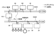
- FIG. 1 is a system diagram showing the configuration of an electric vehicle according to Embodiment 1.
- the electric vehicle is a front wheel drive vehicle, and has front wheels FR and FL which are drive wheels, and rear wheels RR and RL which are driven wheels.
- Each wheel has wheel cylinders W / C (FR), W / C (FL), W / C (RR), W / that generate friction braking force by pressing the brake pads against the brake rotor that rotates integrally with the tire.
- C (RL) also simply referred to as W / C
- wheel speed sensors 9 (FR), 9 (FL), 9 (RR), 9 (RL) (simply both 9) To be described).
- a hydraulic unit 5 is connected to the wheel cylinder W / C through a hydraulic pipe 5a.
- the hydraulic unit 5 includes a plurality of solenoid valves, a reservoir, a pump motor, and a brake controller 50, and controls driving states of various solenoid valves and pump motors based on commands from the brake controller 50.
- the wheel cylinder hydraulic pressure of each wheel is controlled.
- the hydraulic unit 5 may be a well-known brake-by-wire unit or a brake unit including a hydraulic circuit that can execute vehicle stability control, and is not particularly limited.
- the electric motor 1 that is a drive source is provided with a resolver 2 that detects a motor rotation angle.
- a differential gear 3 is connected to the electric motor 1 via a speed reduction mechanism 3a, and a front wheel FR.FL is connected to a drive shaft 4 connected to the differential gear 3.
- a high-voltage battery 6 that supplies electric power to the electric motor 1 or collects regenerative power and a battery controller 60 that monitors and controls the battery state of the high-voltage battery 6 are mounted on the rear side of the vehicle. Yes.
- the inverter 10 interposed between the high voltage battery 6 and the electric motor 1 is controlled by the motor controller 100.
- an auxiliary battery 8 is connected to the high voltage battery 6 via a DC-DC converter 7 (component), and the auxiliary battery 8 functions as a driving power source for the hydraulic unit 5.
- the electric vehicle of the first embodiment is provided with a CAN communication line that is an in-vehicle communication line to which a plurality of controllers mounted on the vehicle are connected, and the brake controller 50, the vehicle controller 110, the battery controller 60, and the like communicate with each other. Connected as possible.
- the power steering controller 20 that controls the power steering device that assists the steering operation of the driver and the meter controller 22 that controls the speed meter that displays the vehicle speed are connected to the CAN communication line. It is connected.
- the power steering controller 20 is provided with a steering angle sensor 21 that detects the steering angle of the steering wheel.
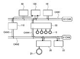
- FIG. 2 is a schematic diagram showing a connection state of various controllers according to the first embodiment.
- the battery controller 60, the motor controller 100, the inverter 10, and the brake controller 50 that control the torque state acting between the drive wheels and the road surface are combined as a power train system, and the first CAN bus CAN1.
- the chassis system such as the power steering controller 20 and the meter controller 22 is connected to the second CAN bus CAN2 (second communication device).
- the first CAN bus CAN1 and the second CAN bus CAN2 are connected by a connection bus CAN3.
- the connection bus CAN3 is provided with a vehicle controller 110, and information transmitted / received in the first CAN bus CAN1 is received by the vehicle controller 110 on the connection bus CAN3 and then output to the second CAN bus CAN2.
- information transmitted / received in the second CAN bus CAN2 is received by the vehicle controller 110 on the connection bus CAN3 and then output to the first CAN bus CAN1.
- FIG. 3 is a schematic diagram illustrating a connection state of various controllers of the comparative example.
- the brake controller 50 is connected to the second CAN bus CAN2 as shown in FIG. This is because, conventionally, the control of the brake system is the control of the chassis system, not the control of the power train system.
- systems such as a power train system, a brake system, a steering system, and a suspension system are often developed as individual systems.
- the brake controller 50 requests the vehicle controller 110 to suppress the slip state. Then, the vehicle controller 110 outputs a request for torque reduction or the like to the motor controller 100 based on the request received from the brake controller 50.
- the brake request output from the brake controller 50 is used as the communication timing. It is output once to the motor controller 100 with a delay, and there has been a scene where a delay has occurred and the drive slip cannot be effectively suppressed.
- the inertia of the driving wheel is extremely smaller than the inertia of the vehicle, and the rotational state is likely to change abruptly.
- the CAN communication line is designed so that various systems can be easily connected later, and only the brake controller increases the control gain and control cycle. However, since it is limited to the communication speed within the CAN communication line, it is difficult to ensure sufficient response.
- the brake controller 50 is a system for controlling the torque between the driving wheel and the road surface
- the brake controller 50 is positioned in the power train system and is connected to the first CAN communication line CAN1.
- the vehicle speed information output from the brake controller 50 is slightly delayed in the timing of transmission into the second CAN bus CAN2, but the vehicle speed does not change suddenly due to the size of the vehicle inertia. There is no problem.
- the vehicle controller 110 that controls the entire vehicle to monitor and control the entire vehicle, but if the centralization that outputs all commands to each controller after collecting all the information is advanced too much The calculation load of the vehicle controller 110 increases, and a very expensive controller is required. Further, the vehicle controller 110 outputs a command in consideration of low communication speed information, and no matter how expensive the vehicle controller 110 is adopted, a vehicle system with good responsiveness cannot be constructed. It is also possible to send and receive all information quickly, but the increase in communication speed is a specification change that affects all other controllers connected to this communication line, and increasing the overall communication speed is complicated. It is very difficult in the system.
- the vehicle controller 110 in addition to dividing the configuration of the CAN communication line into the first CAN bus CAN1 and the second CAN bus CAN2, the vehicle controller 110 does not output all commands but is lower than the vehicle controller 110.
- a configuration was constructed in which the controller of the system made some judgment and controlled.
- the brake request output from the brake controller 50 can be transmitted directly to the motor controller 100 so that the motor controller 100 can determine the final motor torque command value before the vehicle controller 110.
- the motor controller 100 is configured to be able to read a brake request from the brake controller 50 in addition to a normal torque request from the vehicle controller 110 and output a final motor torque command value corresponding to the traveling state.
- FIG. 4 is a control block diagram showing the contents of information transmitted / received by each controller of the first embodiment.
- the vehicle controller 110 inputs accelerator pedal position information and shift position information, calculates a first torque command value based on the basic driver request torque and other control processing results, and the motor controller 100 and the brake controller 50. To output the first torque command value.
- the brake controller 50 inputs the ON / OFF state of the brake switch indicating the brake pedal operation state and the wheel speed signal of each wheel, for example, the second torque command value based on the request for traction control, the hydraulic unit 5 and the brake A torque increase / decrease request indicating whether the controller 50 is operating normally or not, whether the torque is to be increased, decreased, or not increased in response to the driver request.
- the motor controller 100 if the brake device state is normal and the first torque command value is compared with the second torque command value, and the torque increase / decrease request is matched, the second torque command from the brake controller 50 is detected. The value is adopted, and when these conditions are not satisfied, the first torque command value is adopted.
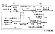
- FIG. 5 is a control block diagram showing a request for traction control provided in the vehicle controller and brake controller of the first embodiment and the control contents executed by the motor controller.
- the driver request torque command value calculation unit 111 in the vehicle controller 110 calculates the driver request torque (first torque command value) based on the accelerator pedal opening and the shift position, and outputs it to the motor controller 100.
- a traction control unit 51 in the brake controller 50 inputs wheel speed information from the wheel speed sensor 9, steering angle information from the steering angle sensor, and actual motor torque output from the electric motor 1. Then, it is determined whether or not the driving wheel is in a driving slip state. When the driving slip occurs, a traction control torque (second torque command value) that suppresses the driving slip is output, and the control contents executed in the brake controller 50 Is output to the motor controller 100.
- a changeover switch 101 for switching which command value to select between the driver request torque and the traction control torque based on the control flag and a control to be described later on the switched torque command value TMCIN * are described.
- a torque adding unit 102 that adds vibration control torque and outputs a final torque command value, and a motor that outputs an inverter drive signal to the inverter 10 to control the current supplied to the electric motor 1 based on the final torque command value
- a current control unit 105 a vibration suppression control information calculation unit 103 for calculating a vibration suppression control gain and a vibration suppression control limit value for suppressing vibration of the drive train generated in the power train system; and the calculated vibration suppression control information.
- a vibration suppression control unit 104 that calculates a vibration suppression control torque that suppresses power train vibrations based on the motor rotation speed.
- FIG. 6 is a flowchart showing the command value selection process of the first embodiment.
- the changeover switch 101 outputs either the driver request torque command value TDRV * or the slip control torque command value TESC * as the torque command value TMCIN * by performing the following determination process.
- an acceleration slip control flag FA and a deceleration slip control flag FD that indicate a slip control state are provided in the traction control unit 51, and an ESC that indicates an abnormal state of the hydraulic pressure unit 5 and the brake controller 50 itself.
- a status flag FH is provided.
- step S1011 it is determined whether or not the ESC state flag FH indicates a no-abnormal state. If there is no abnormality, the process proceeds to step S1012. Without switching the torque command value TMCIN * to the driver request torque command value TDRV *.
- step S1012 it is determined whether or not the acceleration slip control flag FA indicates that control is in progress. If the control is in control, the process proceeds to step S1013. If the control is not in control, the process proceeds to step S1016. In step S1013, it is determined whether or not the slip control torque command value TESC * is equal to or less than the driver request torque command value TDRV *. If the slip control torque command value TESC * is equal to or less than the driver request torque command value TDRV *, the process proceeds to step S1014 and the torque command value TMCIN * Is switched to the slip control torque command value TESC *.
- step S1016 it is determined whether or not the deceleration slip control flag FD indicates that control is in progress. If the control is in progress, the process proceeds to step S1017. If the control is not in control, the process proceeds to step S1020. In step S1017, it is determined whether or not the slip control torque command value TESC * is equal to or greater than the driver request torque command value TDRV *. If the slip control torque command value TESC * is equal to or greater than the driver request torque command value TDRV *, the process proceeds to step S1018 and the torque command value TMCIN * Is switched to the slip control torque command value TESC *.
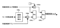
- FIG. 7 is a control block diagram showing a vibration suppression control torque command value calculation process of the first embodiment.
- the vibration suppression control unit 104 includes a vibration component extraction unit 104a that extracts a vibration component from the motor rotation speed.
- the vibration component extraction unit 104a is composed of a high-pass filter, and allows only a predetermined high-frequency component to pass through.
- the gain multiplication unit 104b multiplies the vibration component that has passed through the high-pass filter by the vibration control gain.
- the torque limiter 104c compares the magnitude of the damping control torque limit value and the damping control torque after gain multiplication, and selects the smaller value.
- the negative value multiplication unit 104d multiplies the vibration suppression control torque limit value by a negative value.
- the torque limiter 104e compares the negative value of the damping control torque limit value with the damping control torque after gain multiplication, and selects the larger value. Thus, the vibration suppression control torque corresponding to the vibration component is calculated, and the generation of excessive vibration suppression control torque is suppressed.
- FIG. 8 is a control block diagram showing slip control executed in the traction control unit of the first embodiment.
- the drive wheel speed calculation unit 511 calculates the DC-DC converter 7 based on the detected wheel speed VW.
- the vehicle body speed estimation unit 512 calculates an estimated vehicle body speed VC based on the wheel speed VW.
- the vehicle body speed may be estimated based on the average value of the vehicle body speed calculated from the wheel speed of each wheel of the driven wheel, or the average value of the vehicle body speed calculated from the wheel speed of each of the four wheels, There may be a select low of the driven wheel and the driving wheel (the vehicle speed is obtained by selecting the lower of the wheel speeds of the driven wheel and the driving wheel), and the like is not particularly limited.
- the target drive wheel speed reference value calculation unit 513 is a target drive that is a target speed of each drive wheel based on the vehicle acceleration GC, the steering angle Astr, and the estimated vehicle body speed VC. Calculate the wheel speed reference value VDbase *.
- FIG. 9 is a control block diagram illustrating target drive wheel speed reference value calculation processing according to the first embodiment.
- the acceleration target slip ratio gain calculation unit 513a is provided with an acceleration target slip ratio gain map, and is set to calculate a larger acceleration target slip ratio gain as the detected acceleration GC is larger. . That is, if a large acceleration is obtained, it is considered that a frictional force can be secured with the road surface even if a certain slip ratio is allowed.
- a steering angle target slip ratio gain map is provided, and when the detected steering angle is near the neutral position, a large steering angle target slip ratio gain is calculated.
- the slip ratio calculation unit 513c multiplies the acceleration target slip ratio gain by the steering angle target slip ratio gain, and calculates the target slip ratio in consideration of both states.
- the target slip amount calculation unit 513d calculates the target slip amount by multiplying the calculated target slip rate by the estimated vehicle body speed VC.
- the limiter processing unit 513e performs limit processing on the target slip amount to suppress a sudden change in the target value.
- the adder 513f calculates the target drive wheel speed VD * by adding the target slip amount to the estimated vehicle body speed VC.
- the limiter processing unit 513g performs limiter processing on the target drive wheel speed VD * to calculate a target drive wheel speed reference value VDbase *.
- the yaw rate sensor value is compared with the estimated yaw rate calculated from the steering angle and the estimated vehicle body speed VC. Control may be performed so as to suppress the deviation between the yaw rate sensor value and the estimated yaw rate.
- the acceleration slip control start speed calculation unit 514 calculates a control start speed VS based on the estimated vehicle body speed VC.
- FIG. 13 is a control block diagram illustrating acceleration slip control start speed calculation processing according to the first embodiment.
- the control start slip amount map 514a a larger slip amount is calculated as the estimated vehicle speed VC is higher. This is to make the control start slip ratio almost constant when considering the slip ratio.
- the map 514a sets a certain slip amount.
- the adding unit 514b adds the slip amount calculated from the control start slip amount map 514a to the estimated vehicle body speed VC to calculate the control start speed VS.
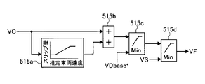
- the acceleration slip control end speed calculation unit 515 calculates a control end speed VF based on the estimated vehicle body speed VC.
- FIG. 14 is a control block diagram illustrating acceleration slip control end speed calculation processing according to the first embodiment.
- the control end slip amount map 515a a larger slip amount is calculated as the estimated vehicle body speed VC is higher.
- the slip amount set in the control end slip amount map 515a is the control start slip amount map. It is set smaller than the slip amount set in 514a.
- the adding unit 515b adds the slip amount calculated from the control end slip amount map 515a to the estimated vehicle body speed VC to calculate a control end speed calculation value.
- the first selection unit 515c selects the smaller value of the control end speed calculated value and the target drive wheel speed reference value VDbase *, so that the control end speed VF is set to the target drive wheel speed reference value VDbase. * Set to the estimated vehicle speed VC side to prevent hunting.
- the second selection unit 515d selects the smaller value of the value selected by the first selection unit 515c and the control start speed VS, so that the control end speed VF is set higher than the control start speed VS. Set to the estimated vehicle speed VC side to prevent hunting. Then, the finally selected value is output as the control end speed VF.
- FIG. 15 is a control block diagram illustrating acceleration slip control flag calculation processing according to the first embodiment.
- FIG. 15 shows the case where the shift lever is in the D range, but basically the same processing is performed even in other shift ranges.
- the control end determination unit 516a compares the drive wheel speed VD with the control end speed VF, and outputs a switching signal to the end-side first switch 516b when the drive wheel speed VD is equal to or lower than the control end speed VF.
- the end-side first switch 516b is a switch for switching between 0 and a counter value composed of the previous value output unit 516C and the count-up unit 516d, and the control ends when 0 is selected during the drive slip control.
- the previous value output unit 516c and the count up unit 516c start counting up and output to the control end delay determination unit 516f.
- the control end delay determination unit 516f indicates that one of the control end conditions is satisfied in the AND condition determination unit 516k when the value output from the end-side first switch 516b is equal to or greater than the preset timer value TimeF. Output a signal. In other words, it is determined whether a time equal to or greater than TimeF has elapsed since the drive wheel speed VD has become equal to or less than the control end speed VF, and when it has elapsed, a signal indicating that one of the control end conditions has been satisfied. Output.
- the torque deviation calculation unit 516g calculates the torque deviation between the driver request torque command value TDRV * and the final torque command value TFB for the electric motor 1, and the absolute value processing unit 516h converts the absolute value into a torque state determination unit. Output to 516j.
- the torque state determination unit 516j outputs a signal that satisfies one of the control end conditions when the torque deviation is equal to or less than a predetermined torque value TrpF set in advance. *
- the AND condition determination unit 516k conditions for termination determination and delay processing based on the drive wheel speed VD are satisfied, and the driver request torque command value TDRV * is substantially equal to the torque commanded to the electric motor 1.
- a control end condition satisfaction signal is output to the OR condition determination unit 516m.
- the negative value determination unit 516l outputs a control end condition establishment signal when the driver required torque TRDV * is 0 or less.
- the OR condition determination unit 516m outputs a switching signal to the control flag switch 516s when either the AND condition determination unit 516k or the negative value determination unit 516l outputs a control end condition establishment signal.
- the control start determination unit 516n compares the drive wheel speed VD with the control start speed VS, and outputs a switching signal to the start side switch 516q when the drive wheel speed VD is equal to or higher than the control start speed VS. In the case of the control start determination, since the slip of the driving wheel is increasing, it is necessary to start the control promptly. Therefore, slip control is started immediately without providing a delay time.
- the start side switch 516q receives the signal of the control flag previous value output unit 516p, which is the previous value of the control flag switch 516s, and outputs a 1 by the switching signal from the control start determination unit 516n. When the condition of the start determination unit 516n is not satisfied, the control flag is switched from 1 to the previous value of the control flag. At this time, if the control end condition establishment signal is not output from the OR condition determination unit 516m, 1 is continuously output from the control flag switch 516s, and thus the control flag is turned on.
- the target drive wheel speed calculation unit 517 calculates the target drive wheel speed VD * based on the target drive wheel speed reference value VDbase *.
- FIG. 10 is a control block diagram illustrating target drive wheel speed calculation processing according to the first embodiment.
- the driving wheel speed VD is set as the initial value as the target driving wheel speed VD *.
- the target value deviation calculation unit 517a calculates a target value deviation between the target drive wheel speed reference value VDbase * and the previous target drive wheel speed VD * calculated by the target drive wheel speed previous value calculation unit 517g.
- the limiter 517b performs limit processing to limit the deviation in order to achieve a smooth torque change, and outputs the limit processing to the first addition unit 517e.
- the change amount calculation unit 517d outputs the previous value of the target drive wheel speed reference value VDbase *.
- the previous target drive wheel speed reference value VDbase * output from the previous value output unit 517c and the current target drive wheel speed reference
- the amount of change is calculated from the difference from the value VDbase * and output to the first addition unit 517e.
- the first addition unit 517e adds the target value deviation and the change amount of the target drive wheel speed reference value VDbase *, and calculates the change amount of the drive wheel speed to be changed in the current control.
- the target drive wheel speed VD * can follow the target drive wheel speed reference value VDbase *.
- the second addition unit 517f calculates the primary target drive wheel speed by adding the value output from the first addition unit 517e to the previous target drive wheel speed VD *, and outputs it to the target drive wheel speed changeover switch 517h.
- the target drive wheel speed changeover switch 517h when the acceleration slip control flag FA is 0, the drive wheel speed VD is output as the final target drive wheel speed VD *, and when the acceleration slip control flag FA is 1, the primary drive wheel speed VD * is output.
- the target drive wheel speed is output as the final target drive wheel speed VD *.
- the acceleration slip control torque command value calculation unit 518 calculates an acceleration slip control torque command value based on the deviation between the drive wheel speed VD and the target drive wheel speed VD *.
- FIG. 11 is a control block diagram illustrating acceleration slip control torque calculation processing according to the first embodiment.
- the speed deviation calculation unit 518a calculates a speed deviation between the target drive wheel speed VD * and the drive wheel speed VD.
- the proportional gain multiplication unit 518b multiplies the speed deviation by the proportional gain Kp and outputs a proportional component.
- the integral gain multiplication unit 518c multiplies the speed deviation by the integral gain Ki.
- the integration unit 518d outputs a value obtained by integrating the final torque command value TFB as an initial value and the smaller one of the driver request torque command value TDRV * as an integral component.
- the PI control amount calculation unit 518e adds a proportional component and an integral component and outputs a PI control torque command value.
- the acceleration slip control torque command determination unit 518f outputs the smaller value of the driver request torque command value TDRV * and the PI control torque command value as the final acceleration slip control torque command value TA *. Since the initial value of the target drive wheel speed VD * is the drive wheel speed VD, the proportional component is zero, and the integral component is also set to the final torque command value TFB, and no deviation occurs immediately after the start of control. Therefore, torque fluctuation is not caused.
- FIG. 12 is a control block diagram illustrating slip control torque command value calculation processing according to the first embodiment.
- the acceleration slip control execution permission flag FAExecOK and the deceleration slip control execution permission flag FDExecOK are the slip control execution permission flags, respectively, when the regeneration prohibited state or the slip control off switch is pressed, or some abnormality (for example, wheel speed sensor abnormality) ) Is prohibited, otherwise it is allowed.
- the acceleration side AND determination unit 519a outputs a switching signal to the acceleration slip control torque command value switch 519c and the NAND determination unit 519e when both the acceleration slip control flag FA and the acceleration slip control execution permission flag FAExecOK satisfy the conditions. To do. Similarly, the deceleration-side AND determination unit 519b switches to the deceleration slip control torque command value switch 519d and the NAND determination unit 519e when both the deceleration slip control flag FD and the deceleration slip control execution permission flag FDExecOK satisfy the conditions. Output a signal.
- the NAND determination unit 519e determines that an abnormality occurs when the acceleration slip control flag FA and the deceleration slip control flag FD are simultaneously established, and outputs the driver request torque command value TDRV * without following the slip control request. It is the structure to process.
- the acceleration slip control torque command value TA * is switched to be output to the slip control torque command value calculation unit 519f, and when the acceleration slip control request is not output, the signal output from the second torque command value changeover switch 519d is Output.
- the second torque command value changeover switch 519d switches from the driver requested torque command value TDRV * to the deceleration slip control torque command value TD * when the deceleration slip control request is output from the deceleration-side AND determination unit 519b.
- the driver request torque command value TDRV * is output to the first torque command value changeover switch 519c.
- the slip control torque command value calculation unit 519f outputs the driver request torque command value TDRV * as the slip control torque command value TESC * when the NAND determination unit 510e makes an abnormality determination, and when the abnormality determination is not made.
- the signal output from the first torque command value changeover switch 519c is output as the slip control torque command value TESC *.
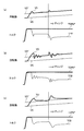
- FIG. 16 is a time chart showing the relationship between the rotational speed and torque when drive slip control is performed.
- FIG. 16A shows a case where the configuration of the first embodiment is adopted
- FIG. 16B shows a case where the configuration of the comparative example of FIG. 3 is adopted and the control gain is increased.
- c) is a case where the configuration of the comparative example of FIG. 3 is adopted and the control gain is lowered.
- TDRV * when a driving slip occurs while outputting the driver required torque command value TDRV *, the acceleration slip control flag FA becomes 1, and driving toward the target driving wheel speed VD * is performed.
- the acceleration slip control torque command value TA * is output so that the wheel speed VD converges.
- the acceleration slip control torque command value TA * is directly output from the traction control unit 51 of the brake controller 50 to the motor controller 100 without passing through the vehicle controller 110, there is no response delay. It can be seen that the target drive wheel speed VD * is well converged.
- traction control with extremely high convergence is achieved with good response. In particular, the fact that the cornering force can be secured due to the good convergence is considered to be a noteworthy matter.
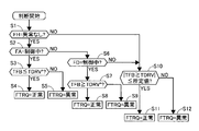
- FIG. 17 is a flowchart showing the control system abnormality determination process of the first embodiment.
- step S1 it is determined whether or not the ESC state flag FH indicates an abnormal state. If there is no abnormality, the process proceeds to step S2, and if there is an abnormality, the process proceeds to step S10.
- step S2 it is determined whether or not the acceleration slip control flag FA indicates that control is in progress. If the control is in control, the process proceeds to step S3.
- step S3 it is determined whether or not the final torque command value TFB is equal to or less than the driver request torque command value TDRV *. Set correctly.
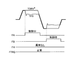
- FIG. 18 is a time chart at the time of slip control according to the first embodiment. That is, in the region where the acceleration slip control flag FA in FIG.
- step S6 it is determined whether or not the deceleration slip control flag FD indicates that control is in progress. If the control is in progress, the process proceeds to step S7. In step S7, it is determined whether or not the final torque command value TFB is equal to or greater than the driver request torque command value TDRV *. If the final torque command value TFB is equal to or greater than the driver request torque command value TDRV *, the process proceeds to step S8 and the flag FTQR indicating the torque control state Set correctly. That is, in the region where the deceleration slip control flag FD in FIG. 18 indicates that control is in progress, a slip occurs due to the generation of regenerative torque as the driver request torque command value TDRV * during the deceleration slip control.
- step S10 it is determined whether or not the absolute value of the difference between the final torque command value TFB and the driver request torque command value TDRV * is equal to or smaller than a predetermined value. Therefore, the flag FTQR is set normally. On the other hand, if the absolute value of the difference is larger than the predetermined value, it cannot be said that the vehicle controller 110 is controlling, and it is determined that there is a possibility of being controlled by the brake controller 50 in which an abnormality has occurred, and the flag FTQR Is set abnormally. As described above, the determination made by the motor controller 100 can be avoided by considering the state of the brake controller 50 and the requirements of the brake controller 50.
- Wheel speed sensor 9 (wheel speed calculation unit) that calculates the speed of the wheel, electric motor 1 that generates braking / driving force on the wheel, and hydraulic unit 5 (hydraulic pressure that generates hydraulic braking force on the wheel)
- a braking device a motor controller 100 for controlling the electric motor 1 based on the command value, and a braking force to be generated on the wheel using the calculated wheel speed, and a hydraulic pressure so that the calculated braking force is generated.
- Brake controller 50 (hydraulic pressure controller) that controls the hydraulic pressure of unit 5, and vehicle controller that calculates driver required torque command value TDRV * (driver required torque command value) according to the driver's accelerator operation or brake operation 110, a first CAN bus CAN1 (first communication device) capable of communication between the brake controller 50 and the motor controller 100, and between the vehicle controller 110 and the motor controller 100.
- the brake controller 50 includes a slip control torque command value TESC * as a command value for generating a braking / driving force in the electric motor 1 based on the calculated wheel speed.
- the brake controller 50 sends the slip control torque command value TESC * to the motor controller 100 via the first CAN bus CAN1, and the vehicle controller 110 sends the driver requested torque command value TDRV via the second CAN bus CAN2.
- the motor controller 100 provides an electric vehicle control system that transmits information on the selected command value to the vehicle controller 110 via the first CAN bus CAN1. Since the vehicle controller 110 can grasp the control state performed by the motor controller 100, the safety of the vehicle can be ensured.
- the vehicle controller 110 receives the received torque command value TESC * (selected command value), the acceleration slip control flag FA, the deceleration slip control flag FD, and the ESC state flag.
- an electric vehicle control system including a control system abnormality determination unit 110a that determines abnormality of a control system based on FH (control state of a vehicle) and a driver request torque command value TDRV *. Therefore, since the vehicle controller 110 can determine the abnormality of the system, the reliability of the system can be improved.
- the control system abnormality determination unit 110a determines whether or not the hydraulic unit 5 is abnormal as a vehicle control state.
- Device abnormality determination unit acceleration slip control flag FA (acceleration slip control state determination unit) for determining whether or not acceleration slip control is being performed as a vehicle control state, and deceleration slip control flag for determining whether or not deceleration slip control is being performed
- An electric vehicle control system including an FD (deceleration slip control state determination unit) is provided. Therefore, an appropriate system state can be grasped according to the control state of the hydraulic unit 5 and the brake controller 50, and the reliability of the system can be improved.
- the control system abnormality determination unit 110a determines that the driver requested torque when the determined state of the hydraulic unit 5 is normal and the acceleration slip control is being performed.
- an electric vehicle control system that determines an abnormality when a command value TDRV * is less than a selected command value. That is, when the final torque command value TFB is equal to or higher than the driver request torque command value TDRV * despite the acceleration slip control, the acceleration slip is promoted. In this case, the process proceeds to step S5 and the flag FTRQ An excessive slip can be avoided by abnormally setting.
- the control system abnormality determination unit 110a determines that the driver requested torque when the determined state of the hydraulic unit 5 is normal and deceleration slip control is being performed.
- an electric vehicle control system that determines that an abnormality occurs when a command value TDRV * is equal to or greater than a final torque command value TFB. That is, when the driver requested torque command value TDRV * is equal to or greater than the final torque command value TFB despite the deceleration slip control, the deceleration slip is promoted. In this case, the process proceeds to step S9 and the flag FTRQ An excessive slip can be avoided by abnormally setting.
- the control system abnormality determination unit 110a is in a state where the determined hydraulic unit 5 is normal and acceleration slip control and deceleration slip control are not controlled. If the difference between the driver request torque command value TDRV * and the final torque command value TFB (selected command value) is greater than or equal to a predetermined value An electric vehicle control system for determining is provided. That is, if the difference is equal to or greater than a predetermined value, it cannot be said that the vehicle controller 110 is controlling the vehicle, and it may be controlled by the brake controller 50 in which an abnormality has occurred. Incorrect determination of the controller 100 can be avoided.
- the first CAN bus CAN1 (first communication device) and the second CAN bus CAN2 (second communication device) provide an electric vehicle control system that is CAN communication.
- a low-cost and stable system can be constructed by using an existing communication device without designing a new communication device.
- the CAN communication is performed by the first CAN bus CAN1, the second CAN bus CAN2 provided in parallel with the first CAN bus CAN1, the first CAN bus CAN1, and the second CAN bus CAN2.
- the vehicle controller 110 is connected on the connection bus CAN3, and the motor controller 100 and the brake controller 50 provide an electric vehicle control system connected on the first CAN bus CAN1. Therefore, data can be transmitted directly from the brake controller 50 to the motor controller 100 without using the vehicle controller 110, and the responsiveness of the control system can be improved.
- a power steering controller 20 (electric power steering device) and a meter controller 22 (speed meter control device) are provided, and the electric motor 1 is provided on the first CAN bus CAN1.
- An inverter 10 (component) for driving is connected, a power steering controller 20 and a meter controller 22 are connected to the second CAN bus, and the brake controller 50 sends the calculated wheel speed information to the first CAN bus CAN1.
- the power steering controller 20 and the meter controller 22 provide an electric vehicle control system that receives the transmitted wheel speed information from the second CAN bus CAN2 via the vehicle controller 110.
- the vehicle controller 110 since the vehicle controller 110 is provided on the connection bus CAN3 between the first CAN bus CAN1 and the second CAN bus CAN2, the vehicle controller 110 can grasp all communication states. Note that the wheel speed information required by the power steering controller 20 and the meter controller 22 is exclusively vehicle speed information and is not an element that changes suddenly like the wheel speed. But there is no problem.
- Vehicle controller 110 that calculates the driver required torque command value TDRV * (driver required torque command value) according to the driver's accelerator or brake operation, and generates braking / driving force on the wheels based on the command value
- the motor controller 100 that controls the electric motor 1 to be controlled and the slip control torque command value TESC * (vehicle required torque command value) are calculated according to the behavior of the vehicle to control the hydraulic unit 5 (actuator) mounted on the vehicle
- a brake controller 50 actuator controller for controlling the electric motor 1 based on the driver requested torque command value TDRV * from the vehicle controller 110 and the slip control torque command value TESC * from the brake controller 50.
- An electric vehicle control system for controlling the vehicle is provided.
- the hydraulic unit 5 is described as an example of the actuator.
- the hydraulic unit 5 is not limited to the hydraulic unit 5, but a four-wheel steering mechanism, a variable steering angle mechanism that provides an auxiliary steering angle, or a damping that performs damping force control.
- a configuration may be adopted in which a torque command value is transmitted to and received from an actuator such as a force variable mechanism.
- the hydraulic pressure unit 5 includes a wheel speed sensor 9 (wheel speed calculation unit) that calculates a wheel speed, and generates a hydraulic braking force on the wheel as an actuator. (Hydraulic braking device), the actuator controller calculates a braking force to be generated on the wheel using the calculated wheel speed, and controls the hydraulic unit 5 so that the calculated braking force is generated.
- An electric vehicle control system that is a (hydraulic pressure controller) is provided. That is, by adopting the brake controller 50 acting in the front-rear direction of the drive wheel, a more responsive power train control system can be realized.
- the first CAN bus CAN1 (first communication device) that connects the brake controller 50 and the motor controller 100, and the vehicle controller 110 and the motor controller 100 are connected.
- a second CAN bus CAN2 (second communication device), and the brake controller 50 uses a slip control torque command value TESC * (as a command value for causing the electric motor 1 to generate braking / driving force based on the calculated wheel speed.
- the brake controller 50 sends the slip control torque command value TESC * to the motor controller 100 via the first CAN bus CAN1, and the vehicle controller 110 sends the driver requested torque via the second CAN bus CAN2.
- the command value TDRV * is transmitted to the motor controller 100, and the motor controller 100 receives the received slip control torque command value TESC * or the driver requested torque command.
- TDRV * a to provide an electric vehicle control system for selecting as a command value for generating the braking-driving force to the electric motor 1. Therefore, the driver request torque command value TDRV * of the vehicle controller 110 and the slip control torque command value TESC * of the brake controller 50 can be directly transmitted to the motor controller 100, and the response of the control system can be improved.
- the motor controller 100 provides electric vehicle control in which information about the selected command value is transmitted to the vehicle controller 110 via the first CAN bus CAN1. Since the vehicle controller 110 can grasp the control state performed by the motor controller 100, the safety of the vehicle can be ensured.
- the vehicle controller 110 receives the received torque command value TESC * (selected command value), the acceleration slip control flag FA, the deceleration slip control flag FD, and the ESC state flag.
- an electric vehicle control system including a control system abnormality determination unit 110a that determines abnormality of a control system based on FH (control state of a vehicle) and a driver request torque command value TDRV *. Therefore, since the vehicle controller 110 can determine the abnormality of the system, the reliability of the system can be improved.
- Wheel speed sensor 9 (wheel speed calculation unit) that calculates the speed of the wheel, electric motor 1 that generates braking / driving force on the wheel, and hydraulic unit 5 (hydraulic pressure that generates hydraulic braking force on the wheel)
- a braking device a motor controller 100 for controlling the electric motor 1 based on the command value, and a braking force to be generated on the wheel using the calculated wheel speed, and a hydraulic pressure so that the calculated braking force is generated.
- a brake controller 50 (hydraulic pressure controller) that controls the unit 5, a vehicle controller 110 that calculates a driver required torque command value TDRV * according to the accelerator operation or brake operation of the driver, a brake controller 50, a motor controller 100, A CAN communication line that connects the vehicle controllers 110 is provided, and the brake controller 50 generates braking / driving force to the electric motor 1 based on the calculated wheel speed.
- the slip controller torque command value TESC * (motor torque command value) is calculated as a command value for causing the brake controller 50 to transmit the slip control torque command value TESC * to the motor controller 100 via the first CAN bus CAN1 (CAN communication line).
- the vehicle controller 110 transmits the driver request torque command value TDRV * to the motor controller 100 via the connection bus CAN3 and the first CAN bus CAN1, and the motor controller 100 receives the slip control torque command value TESC * or the driving
- an electric vehicle control system including a control system for selecting a person-requested torque command value TDRV * as a command value for causing the electric motor 1 to generate braking / driving force. Therefore, it becomes possible to directly transmit the slip control torque command value TESC * of the brake controller 50 to the motor controller 100, and it is possible to ensure good responsiveness and slip convergence with respect to changes in road surface conditions.
- the motor controller 100 provides an electric vehicle control system that transmits information on the selected command value to the vehicle controller 110 via the CAN communication line. Since the vehicle controller 110 can grasp the control state performed by the motor controller 100, the safety of the vehicle can be ensured.
- the vehicle controller 110 receives the received torque command value TESC * (selected command value), the acceleration slip control flag FA, the deceleration slip control flag FD, and the ESC state flag FH.
- TESC * selected command value
- the acceleration slip control flag FA the acceleration slip control flag FA
- the deceleration slip control flag FD the deceleration slip control flag FD
- the ESC state flag FH the ESC state flag FH.
- an electric vehicle control system including a control system abnormality determination unit 110a that determines abnormality of a control system based on (vehicle control state) and a driver request torque command value TDRV *. Therefore, since the vehicle controller 110 can determine the abnormality of the system, the reliability of the system can be improved.
- FIG. 19 is a schematic diagram illustrating a connection state of various controllers according to the second embodiment.
- the battery controller 60, the motor controller 100, and the inverter 10 that control the torque state acting between the drive wheels and the road surface are collectively connected to the first CAN bus CAN1 as a power train system. Yes.
- the chassis system such as the power steering controller 20 and the meter controller 22 is connected to the second CAN bus CAN2.
- the first CAN bus CAN1 and the second CAN bus CAN2 are connected by the first connection bus CAN3 and the second connection bus CAN4.
- the vehicle controller 110 is provided in the first connection bus CAN3, and information transmitted / received in the first CAN bus CAN1 is received by the vehicle controller 110 on the first connection bus CAN3 and then output to the second CAN bus CAN2.
- information transmitted / received in the second CAN bus CAN2 is received by the vehicle controller 110 on the connection bus CAN3 and then output to the first CAN bus CAN1.
- the second connection bus CAN4 is provided with a brake controller 50, and wheel speed information, slip control torque command value TESC *, etc. detected by the brake controller 50 are directly output to the first CAN bus CAN1 and the second CAN bus CAN2. .
- the transmission delay of the torque command value TESC * and the like from the brake controller 50 to the motor controller 100 is avoided by connecting the brake controller 50 to the first CAN bus CAN1.
- the brake controller 50 is arranged on the second connection bus CAN4 so that signals can be transmitted not only to the first CAN bus CAN1 but also to the second CAN bus CAN2 without a delay in response. The point is different. Therefore, although the number of communication chips increases as the number of CAN communication line connection ports increases, information can be transmitted to any CAN communication line without a response delay.
- the CAN communication is performed by the first CAN bus CAN1, the second CAN bus CAN2 provided in parallel with the first CAN bus CAN1, the first CAN bus CAN1, and the second CAN bus CAN2.
- the first connection bus CAN3 and the second connection bus CAN4 are connected, the vehicle controller 110 is connected to the first connection bus CAN3, the brake controller 50 is connected to the second connection bus CAN4, and the first CAN A motor controller 100 and an inverter 10 (component) for driving the electric motor 1 are connected to the bus CAN1, and a power steering controller 20 (power steering device) and a meter controller 22 (speed meter) are connected to the second CAN bus CAN2.
- the brake controller 50 sends the calculated wheel speed to the second connection bus CAN4, and the power steering controller 20 and the meter controller 22 To provide an electric vehicle control system which receives from the 2CAN bus CAN2 a broadcast via the second connection bus CAN4. Therefore, the power steering controller 20 and the meter controller 22 can also obtain the wheel speed information without any response delay, and the responsiveness of the entire system can be improved.
- FIG. 20 is a schematic diagram illustrating a connection state of various controllers according to the third embodiment.
- a battery controller 60 and an inverter 10 that control a torque state acting between the drive wheels and the road surface are collectively connected as a power train system to the first CAN bus CAN1.
- the chassis system such as the brake controller 50, the power steering controller 20 and the meter controller 22 is connected to the second CAN bus CAN2.
- the first CAN bus CAN1 and the second CAN bus CAN2 are connected by the first connection bus CAN3 and the second connection bus CAN4.
- the vehicle controller 110 is provided in the first connection bus CAN3, and information transmitted / received in the first CAN bus CAN1 is received by the vehicle controller 110 on the first connection bus CAN3 and then output to the second CAN bus CAN2.
- information transmitted / received in the second CAN bus CAN2 is received by the vehicle controller 110 on the connection bus CAN3 and then output to the first CAN bus CAN1.
- the second connection bus CAN4 is provided with a motor controller 100, and wheel speed information and slip control torque command value TESC * detected by the brake controller 50 on the second CAN bus CAN2 are transmitted via the second CAN bus CAN2. Directly output to the second connection bus CAN4.
- the transmission delay of the torque command value TESC * and the like from the brake controller 50 to the motor controller 100 is avoided by connecting the brake controller 50 to the first CAN bus CAN1.
- the brake controller 50 is arranged on the second CAN bus CAN2 as in the prior art, and the motor controller 100 is arranged on the second connection bus CAN4.
- the wheel speed information and slip from the brake controller 50 The difference is that the control torque command value TESC * can be received via the second CAN bus CAN2 ⁇ second connection bus CAN4 without a response delay.
- the number of communication chips mounted increases as the number of CAN communication line connection ports of the motor controller 100 increases, information can be received with no response delay for any CAN communication line.
- CAN communication is performed using the first CAN bus CAN1, the second CAN bus CAN2 provided in parallel with the first CAN bus CAN1, the first CAN bus CAN1, and the second CAN bus CAN2.
- the first connection bus CAN3 and the second connection bus CAN4 are connected, the vehicle controller 110 is connected to the first connection bus CAN3, the motor controller 100 is connected to the second connection bus CAN4, and the first CAN bus
- An inverter 10 (component) for driving the electric motor is connected to CAN1, and a brake controller 50, a power steering controller 20 (power steering device), and a meter controller 22 (speed meter) are connected to the second CAN bus CAN2.
- the brake controller 50 sends the calculated wheel speed information to the second CAN bus CAN2, and the power steering controller 20 and the meter controller 22 send the sent wheel speed.
- the brake controller 50 sends the calculated wheel speed information to the second CAN bus CAN2, and the power steering controller 20 and the meter controller 22 send the sent wheel speed.
- a wheel speed calculation unit that calculates a wheel speed, an electric motor that generates a braking / driving force on the wheel, a hydraulic braking device that generates a hydraulic braking force on the wheel, and a command value based on the command value
- a motor controller that controls the electric motor, a hydraulic controller that calculates a braking force to be generated on the wheel using the calculated wheel speed, and controls the hydraulic braking device to generate the calculated braking force;
- a vehicle controller that calculates a driver-requested torque command value corresponding to the driver's accelerator operation or brake operation, a first communication device that can communicate between the hydraulic pressure controller and the motor controller, and the vehicle controller A second communication device capable of communicating with the motor controller, wherein the hydraulic controller is calculated
- a motor torque command value is calculated as a command value for causing the electric motor to generate braking / driving force based on wheel speed, and the hydraulic controller transmits the motor torque command value to the motor controller by the first communication device.
- the vehicle controller transmits the driver request torque command value to the motor controller through the second communication device, and the motor controller receives the received motor torque command value or the driver request torque command value as the An electric vehicle control system including a control system that is selected as a command value for generating braking / driving force in an electric motor.
- the vehicle controller is configured to control the control system based on the received selected command value, a vehicle control state, and the driver request torque command value.
- the electric vehicle control system provided with the control-system abnormality determination part which determines abnormality of this.
- the control system abnormality determination unit determines whether or not the hydraulic braking device is abnormal as a control state of the vehicle.
- An electric vehicle control system comprising: an acceleration slip control state determination unit that determines whether or not acceleration slip control is being performed as a control state of the vehicle; and a deceleration slip control state determination unit that determines whether or not the vehicle is decelerating slip control.
- the control system abnormality determination unit performs the operation when the determined state of the hydraulic braking device is normal and the acceleration slip control is being performed.
- the electric vehicle control system which judges that it is abnormal when a person demand torque is less than the selected command value.
- the control system abnormality determination unit performs the operation when the determined state of the hydraulic braking device is normal and the deceleration slip control is being performed.
- the electric vehicle control system which judges that it is abnormal when a person demand torque is more than the selected command value.
- the control system abnormality determination unit determines that the determined state of the hydraulic braking device is normal, and the acceleration slip control and the deceleration slip control are performed. An electric vehicle that is determined to be abnormal if the difference between the driver request torque and the selected command value is greater than or equal to a predetermined value when the control is not being performed or when the determined state of the hydraulic braking device is abnormal Control system.
- the CAN communication includes a first CAN bus, a second CAN bus provided in parallel with the first CAN bus, the first CAN bus, and the second CAN bus.
- An electric vehicle control system wherein the vehicle controller is connected on the connection bus, and the motor controller and the hydraulic controller are connected on the first CAN bus.
- the CAN communication includes a first CAN bus, a second CAN bus provided in parallel to the first CAN bus, the first CAN bus, and the second CAN bus.
- a first connection bus and a second connection bus wherein the vehicle controller is connected to the first connection bus, the hydraulic controller is connected to the second connection bus, and the first CAN bus Is connected to the motor controller and a component for driving the electric motor, and the second CAN bus is connected to the power steering device and a speed meter, and the hydraulic pressure controller calculates the calculated wheel speed to the second
- the power steering device and the speed meter device receive the transmitted wheel speed information from the second CAN bus via the second connection bus.
- the CAN communication includes a first CAN bus, a second CAN bus provided in parallel with the first CAN bus, the first CAN bus, and the second CAN bus.
- the vehicle controller is connected to the first connection bus
- the motor controller is connected to the second connection bus
- the first CAN bus is connected to the first CAN bus
- Components for driving the electric motor are connected
- the hydraulic controller, the power steering device, and a speed meter are connected to the second CAN bus
- the hydraulic controller sends the calculated wheel speed information to the second CAN bus.
- An electric vehicle control system that transmits to the second CAN bus, and the power steering device and speed meter receive the transmitted wheel speed information from the second CAN bus.
- a vehicle controller that calculates a driver-requested torque command value according to a driver's accelerator operation or brake operation, a motor controller that controls an electric motor that generates braking / driving force on wheels based on the command value, and a vehicle An actuator controller that calculates a vehicle request torque command value according to the behavior of the vehicle and controls an actuator mounted on the vehicle, wherein the motor controller includes a driver request torque command value from the vehicle controller and the actuator.
- An electric vehicle control system for controlling the electric motor based on a vehicle request torque command value from a controller.
- the electric vehicle control system further including a wheel speed calculation unit that calculates a wheel speed, and a hydraulic braking device that generates a hydraulic braking force on the wheel as the actuator.
- the actuator controller calculates a braking force to be generated on the wheel using the calculated wheel speed and controls the hydraulic braking device so that the calculated braking force is generated. .
- a first communication device that connects the hydraulic controller and the motor controller, and a second communication device that connects the vehicle controller and the motor controller;
- the hydraulic controller calculates a motor torque command value as a command value for generating a braking / driving force to the electric motor based on the calculated wheel speed, and the hydraulic controller is configured to transmit the first communication.
- the motor torque command value is transmitted to the motor controller via a device, the vehicle controller transmits the driver request torque command value to the motor controller via the second communication device, and the motor controller receives The motor torque command value or the driver required torque command value is transmitted to the electric motor.
- An electric vehicle control system selected as a command for generating braking / driving force.
- the motor controller transmits information on the selected command value to the vehicle controller by the first communication device.
- the vehicle controller is configured to control the control system based on the received selected command value, a vehicle control state, and the driver request torque command value.
- the electric vehicle control system provided with the control-system abnormality determination part which determines abnormality of this.
- a wheel speed calculation unit that calculates the speed of the wheel, an electric motor that generates braking / driving force on the wheel, a hydraulic braking device that generates hydraulic braking force on the wheel, and a command value based on the command value
- a motor controller that controls the electric motor, a hydraulic controller that calculates a braking force to be generated on the wheel using the calculated wheel speed, and controls the hydraulic braking device to generate the calculated braking force;
- a vehicle controller that calculates a driver request torque command value according to a driver's accelerator operation or brake operation, and a CAN communication line that connects between the hydraulic controller, the motor controller, and the vehicle controller, and the hydraulic controller Is a command value for causing the electric motor to generate a braking / driving force based on the calculated wheel speed.
- the hydraulic torque controller sends the motor torque command value to the motor controller via the CAN communication line, and the vehicle controller sends the driver request via the CAN communication line.
- a torque command value is transmitted to the motor controller, and the motor controller selects the received motor torque command value or the driver request torque command value as a command value for causing the electric motor to generate braking / driving force.
- Electric vehicle control system equipped with a system.
- the vehicle controller is configured to control the control system based on the received selected command value, a vehicle control state, and the driver request torque command value.
- the electric vehicle control system provided with the control-system abnormality determination part which determines abnormality of this.
- the first communication device can transmit the motor torque command value from the hydraulic controller to the motor controller without going through the vehicle controller, and can respond well to changes in road surface conditions. And slip convergence can be secured.
- Patent Document 1 The entire disclosure including the specification, claims, drawings and abstract of Japanese Patent Publication No. 2007-74817 (Patent Document 1) is incorporated herein by reference in its entirety.
Landscapes
- Engineering & Computer Science (AREA)
- Mechanical Engineering (AREA)
- Transportation (AREA)
- Power Engineering (AREA)
- Sustainable Energy (AREA)
- Life Sciences & Earth Sciences (AREA)
- Sustainable Development (AREA)
- Chemical & Material Sciences (AREA)
- Combustion & Propulsion (AREA)
- Automation & Control Theory (AREA)
- Physics & Mathematics (AREA)
- Electromagnetism (AREA)
- Electric Propulsion And Braking For Vehicles (AREA)
- Regulating Braking Force (AREA)
Abstract
Description
以下、実施例1に記載の電動車両制御システムの奏する作用効果を列挙する。
Claims (20)
- 電動車両制御システムであって、
車輪の速度を算出する車輪速算出部と、
前記車輪に制駆動力を発生させる電動モータと、
前記車輪に対し液圧制動力を発生させる液圧制動装置と、
指令値に基づいて前記電動モータをコントロールするモータコントローラと、
前記算出された車輪速度を用いて前記車輪に発生させる制動力を算出し、該算出した制動力が発生するよう前記液圧制動装置をコントロールする液圧コントローラと、
運転者のアクセル操作又はブレーキ操作に応じた運転者要求トルク指令値を算出する車両コントローラと、
前記液圧コントローラと前記モータコントローラとの間で通信可能な第1通信装置と、
前記車両コントローラと前記モータコントローラとの間で通信可能な第2通信装置と、を備え、
前記液圧コントローラは前記算出された車輪速に基づいて前記電動モータに制駆動力を発生させるための指令値としてモータトルク指令値を算出し、
前記液圧コントローラは前記第1通信装置により前記モータトルク指令値を前記モータコントローラに送信し、
前記車両コントローラは前記第2通信装置により前記運転者要求トルク指令値を前記モータコントローラに送信し、
前記モータコントローラは、受信した前記モータトルク指令値又は前記運転者要求トルク指令値を、前記電動モータに制駆動力を発生させるための指令値として選択する制御系を備えた、電動車両制御システム。 - 請求項1に記載の電動車両制御システムにおいて、
前記モータコントローラは前記選択した指令値に関する情報を前記第1通信装置によって前記車両コントローラへ送信する、電動車両制御システム。 - 請求項1に記載の電動車両制御システムにおいて、
前記車両コントローラは、受信した前記選択した指令値と、車両の制御状態と、前記運転者要求トルク指令値とに基づき、前記制御系の異常を判定する制御系異常判定部を備えた、電動車両制御システム。 - 請求項3に記載の電動車両制御システムにおいて、
前記制御系異常判定部は、前記車両の制御状態として、液圧制動装置が異常か否かを判定する液圧制動装置異常判定部と、前記車両の制御状態として加速スリップ制御中か否かを判定する加速スリップ制御状態判定部及び減速スリップ制御中か否かを判定する減速スリップ制御状態判定部とを備えた、電動車両制御システム。 - 請求項4に記載の電動車両制御システムにおいて、
前記制御系異常判定部は、判定された前記液圧制動装置の状態が正常であって、前記加速スリップ制御中の場合に前記運転者要求トルクが前記選択した指令値未満の場合に異常と判定する、電動車両制御システム。 - 請求項4に記載の電動車両制御システムにおいて、
前記制御系異常判定部は、判定された前記液圧制動装置の状態が正常であって、前記減速スリップ制御中の場合に前記運転者要求トルクが前記選択した指令値以上の場合に異常と判定する、電動車両制御システム。 - 請求項4に記載の電動車両制御システムにおいて、
前記制御系異常判定部は、判定された前記液圧制動装置の状態が正常であって、前記加速スリップ制御及び前記減速スリップ制御が非制御中の場合、又は、判定された前記液圧制動装置の状態が異常の場合において、前記運転者要求トルクと前記選択した指令値の差が所定値以上の場合に異常と判定する、電動車両制御システム。 - 請求項1に記載の電動車両制御システムにおいて、
前記第1通信装置及び第2通信装置はCAN通信である、電動車両制御システム。 - 請求項8に記載の電動車両制御システムにおいて、
前記CAN通信は第1CANバスと、前記第1CANバスに並列に設けられた第2CANバスと、前記第1CANバスと前記第2CANバスを接続する接続バスとを有し、
前記車両コントローラは前記接続バス上に接続され、前記モータコントローラと前記液圧コントローラは前記第1CANバス上に接続されている、電動車両制御システム。 - 請求項8に記載の電動車両制御システムにおいて、
電動パワーステアリング装置及び速度メータ制御装置を備え、
前記第1CANバスには、前記電動モータを駆動するためのコンポーネントが接続され、前記第2CANバスには、前記パワーステアリング装置及び速度メータ装置が接続され、
前記液圧コントローラは前記算出された車輪速度の情報を前記第1CANバスに送出し、
前記パワーステアリング装置及び速度メータは送出された車輪速度の情報を前記車両コントローラを介して前記第2CANバスから受信する、電動車両制御システム。 - 請求項8に記載の電動車両制御御システムにおいて、
前記CAN通信は第1CANバスと、前記第1CANバスに並列に設けられた第2CANバスと、前記第1CANバスと前記第2CANバスとを接続する第1接続バスと第2接続バスとを有し、
前記第1接続バスには前記車両コントローラが接続され、前記第2接続バスには前記液圧コントローラが接続され、
前記第1CANバスには前記モータコントローラと前記電動モータを駆動するためのコンポーネントが接続され、
前記第2CANバスには、前記パワーステアリング装置及び速度メータが接続され、
前記液圧コントローラは算出した車輪速度を前記第2接続バスに送出し、
前記パワーステアリング装置及び速度メータ装置は、送出された車輪速度の情報を前記第2接続バスを経由して前記第2CANバスから受信する、電動車両制御システム。 - 請求項8に記載の電動車両制御御システムにおいて、
前記CAN通信は第1CANバスと、前記第1CANバスに並列に設けられた第2CANバスと、前記第1CANバスと前記第2CANバスを接続する第1接続バスと第2接続バスとを有し、
前記第1接続バスには前記車両コントローラが接続され、前記第2接続バスには前記モータコントローラが接続され、
前記第1CANバスには前記電動モータを駆動するためのコンポーネントが接続され、
前記第2CANバスには、前記液圧コントローラ及び前記パワーステアリング装置及び速度メータが接続され、
前記液圧コントローラは、算出した車輪速度の情報を前記前記第2CANバスに送出し、前記パワーステアリング装置及び速度メータは送出された車輪速度の情報を前記第2CANバスから受信する、電動車両制御システム。 - 電動車両制御システムであって、
運転者のアクセル操作又はブレーキ操作に応じた運転者要求トルク指令値を算出する車両コントローラと、
指令値に基づいて車輪に制駆動力を発生させる電動モータをコントロールするモータコントローラと、
車両の挙動に応じて車両要求トルク指令値を算出し、車両に搭載されたアクチュエータをコントロールするアクチュエータコントローラと、を備え、
前記モータコントローラは、前記車両コントローラからの運転者要求トルク指令値と、前記アクチュエータコントローラからの車両要求トルク指令値とに基づいて前記電動モータをコントロールする、電動車両制御システム。 - 請求項13に記載の電動車両制御システムにおいて、
車輪の速度を算出する車輪速度算出部を備え、
前記アクチュエータとして前記車輪に対し液圧制動力を発生させる液圧制動装置を備え、
前記アクチュエータコントローラは、前記算出された車輪速度を用いて前記車輪に発生させる制動力を算出し、該算出した制動力が発生するよう前記液圧制動装置をコントロールする液圧コントローラである、電動車両制御システム。 - 請求項14に記載の電動車両制御システムにおいて、
前記液圧コントローラと前記モータコントローラとを接続する第1通信装置と、
前記車両コントローラと前記モータコントローラとを接続する第2通信装置と、を備え、
前記液圧コントローラは前記算出された車輪速に基づいて前記電動モータに制駆動力を発生させるための指令値としてモータトルク指令値を算出し、
前記液圧コントローラは前記第1通信装置を介して前記モータトルク指令値を前記モータコントローラに送信し、
前記車両コントローラは前記第2通信装置を介して前記運転者要求トルク指令値を前記モータコントローラに送信し、
前記モータコントローラは、受信した前記モータトルク指令値又は前記運転者要求トルク指令値を前記電動モータに制駆動力を発生させるための指令値として選択する、電動車両制御システム。 - 請求項15に記載の電動車両制御システムにおいて、
前記モータコントローラは前記選択した指令値に関する情報を前記第1通信装置によって前記車両コントローラへ送信する、電動車両制御システム。 - 請求項16に記載の電動車両制御システムにおいて、
前記車両コントローラは、受信した前記選択した指令値と、車両の制御状態と、前記運転者要求トルク指令値とに基づき、前記制御系の異常を判定する制御系異常判定部を備えた、電動車両制御システム。 - 電動車両制御システムであって、
車輪の速度を算出する車輪速算出部と、
前記車輪に制駆動力を発生させる電動モータと、
前記車輪に対し液圧制動力を発生させる液圧制動装置と、
指令値に基づいて前記電動モータをコントロールするモータコントローラと、
前記算出された車輪速度を用いて前記車輪に発生させる制動力を算出し、該算出した制動力が発生するよう前記液圧制動装置をコントロールする液圧コントローラと、
運転者のアクセル操作又はブレーキ操作に応じた運転者要求トルク指令値を算出する車両コントローラと、
前記液圧コントローラと前記モータコントローラ及び車両コントローラ間を接続するCAN通信線を備え、
前記液圧コントローラは、前記算出された車輪速に基づいて前記電動モータに制駆動力を発生させるための指令値としてモータトルク指令値を算出し、
前記液圧コントローラは前記CAN通信線を介して前記モータトルク指令値を前記モータコントローラに送信し、
前記車両コントローラは前記CAN通信線を介して前記運転者要求トルク指令値を前記モータコントローラに送信し、
前記モータコントローラは、受信した前記モータトルク指令値又は前記運転者要求トルク指令値を前記電動モータに制駆動力を発生させるための指令値として選択する制御系を備えた、電動車両制御システム。 - 請求項18に記載の電動車両制御システムにおいて、
前記モータコントローラは、前記選択した指令値に関する情報を前記CAN通信線によって前記車両コントローラへ送信する、電動車両制御システム。 - 請求項19に記載の電動車両制御システムにおいて、
前記車両コントローラは、受信した前記選択した指令値と、車両の制御状態と、前記運転者要求トルク指令値とに基づき、前記制御系の異常を判定する制御系異常判定部を備えた、電動車両制御システム。
Priority Applications (4)
| Application Number | Priority Date | Filing Date | Title |
|---|---|---|---|
| US14/914,365 US9827873B2 (en) | 2013-08-30 | 2014-08-08 | Electric vehicle control system |
| KR1020167001834A KR101853216B1 (ko) | 2013-08-30 | 2014-08-08 | 전동 차량 제어 시스템 |
| EP14840204.3A EP3040233B1 (en) | 2013-08-30 | 2014-08-08 | Electric vehicle control system |
| CN201480046856.0A CN105492279B (zh) | 2013-08-30 | 2014-08-08 | 电动车辆控制系统 |
Applications Claiming Priority (2)
| Application Number | Priority Date | Filing Date | Title |
|---|---|---|---|
| JP2013-178904 | 2013-08-30 | ||
| JP2013178904A JP6182770B2 (ja) | 2013-08-30 | 2013-08-30 | 電動車両制御システム |
Publications (1)
| Publication Number | Publication Date |
|---|---|
| WO2015029752A1 true WO2015029752A1 (ja) | 2015-03-05 |
Family
ID=52586321
Family Applications (1)
| Application Number | Title | Priority Date | Filing Date |
|---|---|---|---|
| PCT/JP2014/071055 WO2015029752A1 (ja) | 2013-08-30 | 2014-08-08 | 電動車両制御システム |
Country Status (6)
| Country | Link |
|---|---|
| US (1) | US9827873B2 (ja) |
| EP (1) | EP3040233B1 (ja) |
| JP (1) | JP6182770B2 (ja) |
| KR (1) | KR101853216B1 (ja) |
| CN (1) | CN105492279B (ja) |
| WO (1) | WO2015029752A1 (ja) |
Cited By (2)
| Publication number | Priority date | Publication date | Assignee | Title |
|---|---|---|---|---|
| CN106218415A (zh) * | 2016-07-22 | 2016-12-14 | 深圳市大地和电气股份有限公司 | 一种电机扭矩的监控系统及方法 |
| CN115027282A (zh) * | 2022-05-23 | 2022-09-09 | 一汽解放汽车有限公司 | 电机控制系统及方法 |
Families Citing this family (27)
| Publication number | Priority date | Publication date | Assignee | Title |
|---|---|---|---|---|
| JP6167363B2 (ja) * | 2013-09-12 | 2017-07-26 | 日立オートモティブシステムズ株式会社 | 電動車両の制御装置及び電動車両の制御方法 |
| JP5850035B2 (ja) | 2013-12-12 | 2016-02-03 | トヨタ自動車株式会社 | ハイブリッド車両の制御装置 |
| DE102015200122B4 (de) * | 2015-01-08 | 2016-11-03 | Robert Bosch Gmbh | Verfahren und Vorrichtung zum Betreiben eines Kraftfahrzeugs mit einer Sicherheitseinrichtung zur Kompensation fehlerhafter Drehmomente |
| WO2017150445A1 (ja) * | 2016-02-29 | 2017-09-08 | 日本精工株式会社 | 電動パワーステアリング装置 |
| JP6571863B2 (ja) * | 2016-03-15 | 2019-09-04 | 日立オートモティブシステムズ株式会社 | パワーステアリング装置の制御装置 |
| GB2553121B (en) * | 2016-08-24 | 2019-02-06 | Jaguar Land Rover Ltd | Watchdog controller |
| CN106379199A (zh) * | 2016-11-01 | 2017-02-08 | 南通濠诚文化传媒有限公司 | 一种廉价型简易电动汽车 |
| AU2018228169B2 (en) * | 2017-03-03 | 2021-03-25 | Hiroaki Nakaya | Thermoelectric conversion module provided with photothermal conversion substrate |
| CN107009916B (zh) * | 2017-03-08 | 2020-03-24 | 同济大学 | 考虑驾驶员意图分布式驱动电动汽车防滑控制系统及方法 |
| JP6683178B2 (ja) * | 2017-06-02 | 2020-04-15 | トヨタ自動車株式会社 | 自動運転システム |
| JP6539321B2 (ja) * | 2017-09-25 | 2019-07-03 | 株式会社Subaru | 車両の制御システム及び車両の制御方法 |
| JP6973151B2 (ja) * | 2018-02-14 | 2021-11-24 | トヨタ自動車株式会社 | モータの制御装置 |
| CN112055676A (zh) * | 2018-05-03 | 2020-12-08 | 麦格纳国际公司 | 电子控制的轮轴制动系统和方法 |
| CN109532806B (zh) * | 2019-01-23 | 2024-02-27 | 南京林业大学 | 一种纯电动汽车的电子电气系统 |
| KR102654422B1 (ko) * | 2019-03-14 | 2024-04-04 | 한국자동차연구원 | 전기자동차 고장 진단 장치 및 방법 |
| KR20200115820A (ko) * | 2019-03-27 | 2020-10-08 | 현대자동차주식회사 | 하이브리드 자동차 및 그를 위한 제동 제어 방법 |
| CN110466361B (zh) * | 2019-08-14 | 2021-06-01 | 东风汽车集团有限公司 | 两轮轮毂电机驱动纯电动汽车整车控制器及控制方法 |
| CN110696745A (zh) * | 2019-10-12 | 2020-01-17 | 湖北三江航天万山特种车辆有限公司 | 一种大型线缆盘运输车的电气系统 |
| KR20210057895A (ko) * | 2019-11-12 | 2021-05-24 | 현대자동차주식회사 | 급발진 제어 장치 및 방법 |
| JP7384118B2 (ja) * | 2020-06-16 | 2023-11-21 | トヨタ自動車株式会社 | 異常要因判定装置、車両用制御装置、および車両用制御システム |
| CN111572628A (zh) * | 2020-06-29 | 2020-08-25 | 徐州徐工铁路装备有限公司 | 转运车辆和转运车辆的转向方法 |
| CN114056108B (zh) * | 2020-07-29 | 2024-02-13 | 上海汽车集团股份有限公司 | 一种扭矩控制方法和相关装置 |
| KR20220019142A (ko) | 2020-08-06 | 2022-02-16 | 현대자동차주식회사 | 전동 차량의 회생 제동 제어 장치 및 방법 |
| CN112677903A (zh) * | 2020-12-31 | 2021-04-20 | 大运汽车股份有限公司 | 新能源商用车智能驾驶线控底盘控制系统及控制方法 |
| CN113954783B (zh) * | 2021-10-29 | 2022-12-23 | 东风商用车有限公司 | 一种基于驱动电机控制的防盗车方法 |
| CN114475276B (zh) * | 2022-03-04 | 2024-04-19 | 广汽埃安新能源汽车有限公司 | 一种驱动电机力矩的控制方法及系统 |
| CN115903696A (zh) * | 2022-11-11 | 2023-04-04 | 瑞莱铂(盐城)机器人科技有限公司 | 一种agv小车的硬件架构及其工作方法 |
Citations (4)
| Publication number | Priority date | Publication date | Assignee | Title |
|---|---|---|---|---|
| JP2007074817A (ja) | 2005-09-07 | 2007-03-22 | Honda Motor Co Ltd | 電動車両の制御装置 |
| JP2007288904A (ja) * | 2006-04-14 | 2007-11-01 | Toyota Motor Corp | 車両およびその制御方法 |
| JP2008306815A (ja) * | 2007-06-06 | 2008-12-18 | Toyota Motor Corp | 車両用制動制御装置 |
| WO2011027393A1 (ja) * | 2009-09-02 | 2011-03-10 | トヨタ自動車株式会社 | ブレーキ制御装置 |
Family Cites Families (8)
| Publication number | Priority date | Publication date | Assignee | Title |
|---|---|---|---|---|
| JP3541621B2 (ja) * | 1997-06-10 | 2004-07-14 | トヨタ自動車株式会社 | 車両用制動装置 |
| JP4147976B2 (ja) | 2002-09-13 | 2008-09-10 | 日産自動車株式会社 | 複合ブレーキの協調制御装置 |
| US6876098B1 (en) * | 2003-09-25 | 2005-04-05 | The United States Of America As Represented By The Administrator Of The Environmental Protection Agency | Methods of operating a series hybrid vehicle |
| US8608255B2 (en) | 2006-04-14 | 2013-12-17 | Toyota Jidosha Kabushiki Kaisha | Vehicle and control method of vehicle |
| US7957881B2 (en) * | 2006-10-04 | 2011-06-07 | Toyota Jidosha Kabushiki Kaisha | Vehicle and method of controlling driving force for the vehicle based on detected slip of the drive wheel |
| US8135526B2 (en) * | 2007-11-03 | 2012-03-13 | GM Global Technology Operations LLC | Method for controlling regenerative braking and friction braking |
| JP5401999B2 (ja) * | 2008-03-03 | 2014-01-29 | 日産自動車株式会社 | 車両のトラクション制御装置 |
| JP5302749B2 (ja) | 2009-04-20 | 2013-10-02 | 富士重工業株式会社 | 電気自動車の制御装置 |
-
2013
- 2013-08-30 JP JP2013178904A patent/JP6182770B2/ja active Active
-
2014
- 2014-08-08 KR KR1020167001834A patent/KR101853216B1/ko active IP Right Grant
- 2014-08-08 EP EP14840204.3A patent/EP3040233B1/en active Active
- 2014-08-08 WO PCT/JP2014/071055 patent/WO2015029752A1/ja active Application Filing
- 2014-08-08 US US14/914,365 patent/US9827873B2/en active Active
- 2014-08-08 CN CN201480046856.0A patent/CN105492279B/zh active Active
Patent Citations (4)
| Publication number | Priority date | Publication date | Assignee | Title |
|---|---|---|---|---|
| JP2007074817A (ja) | 2005-09-07 | 2007-03-22 | Honda Motor Co Ltd | 電動車両の制御装置 |
| JP2007288904A (ja) * | 2006-04-14 | 2007-11-01 | Toyota Motor Corp | 車両およびその制御方法 |
| JP2008306815A (ja) * | 2007-06-06 | 2008-12-18 | Toyota Motor Corp | 車両用制動制御装置 |
| WO2011027393A1 (ja) * | 2009-09-02 | 2011-03-10 | トヨタ自動車株式会社 | ブレーキ制御装置 |
Non-Patent Citations (1)
| Title |
|---|
| See also references of EP3040233A4 |
Cited By (3)
| Publication number | Priority date | Publication date | Assignee | Title |
|---|---|---|---|---|
| CN106218415A (zh) * | 2016-07-22 | 2016-12-14 | 深圳市大地和电气股份有限公司 | 一种电机扭矩的监控系统及方法 |
| CN115027282A (zh) * | 2022-05-23 | 2022-09-09 | 一汽解放汽车有限公司 | 电机控制系统及方法 |
| CN115027282B (zh) * | 2022-05-23 | 2024-05-14 | 一汽解放汽车有限公司 | 电机控制系统及方法 |
Also Published As
| Publication number | Publication date |
|---|---|
| CN105492279A (zh) | 2016-04-13 |
| US20160200324A1 (en) | 2016-07-14 |
| KR20160024948A (ko) | 2016-03-07 |
| EP3040233A4 (en) | 2017-05-17 |
| EP3040233A1 (en) | 2016-07-06 |
| JP6182770B2 (ja) | 2017-08-23 |
| EP3040233B1 (en) | 2021-02-17 |
| KR101853216B1 (ko) | 2018-04-27 |
| US9827873B2 (en) | 2017-11-28 |
| CN105492279B (zh) | 2018-10-12 |
| JP2015050784A (ja) | 2015-03-16 |
Similar Documents
| Publication | Publication Date | Title |
|---|---|---|
| JP6182770B2 (ja) | 電動車両制御システム | |
| JP6167363B2 (ja) | 電動車両の制御装置及び電動車両の制御方法 | |
| JP6201209B2 (ja) | 駆動力制御装置及び駆動力制御方法 | |
| JP6201210B2 (ja) | 電動車両の制御装置及び電動車両の制御方法 | |
| EP3050765B1 (en) | Control device for electric vehicle | |
| EP3127738A1 (en) | Vehicle control device and vehicle control method | |
| WO2014013991A1 (ja) | 車両用制動力発生装置 | |
| US9895978B2 (en) | Braking force control method for vehicle | |
| EP1935737A1 (en) | A braking system and a method for braking a vehicle |
Legal Events
| Date | Code | Title | Description |
|---|---|---|---|
| WWE | Wipo information: entry into national phase |
Ref document number: 201480046856.0 Country of ref document: CN |
|
| 121 | Ep: the epo has been informed by wipo that ep was designated in this application |
Ref document number: 14840204 Country of ref document: EP Kind code of ref document: A1 |
|
| ENP | Entry into the national phase |
Ref document number: 20167001834 Country of ref document: KR Kind code of ref document: A |
|
| WWE | Wipo information: entry into national phase |
Ref document number: 14914365 Country of ref document: US |
|
| NENP | Non-entry into the national phase |
Ref country code: DE |
|
| REEP | Request for entry into the european phase |
Ref document number: 2014840204 Country of ref document: EP |
|
| WWE | Wipo information: entry into national phase |
Ref document number: 2014840204 Country of ref document: EP |