WO2015029538A1 - アイアン型ゴルフクラブヘッド、及びこれを備えたゴルフクラブセット - Google Patents
アイアン型ゴルフクラブヘッド、及びこれを備えたゴルフクラブセット Download PDFInfo
- Publication number
- WO2015029538A1 WO2015029538A1 PCT/JP2014/065206 JP2014065206W WO2015029538A1 WO 2015029538 A1 WO2015029538 A1 WO 2015029538A1 JP 2014065206 W JP2014065206 W JP 2014065206W WO 2015029538 A1 WO2015029538 A1 WO 2015029538A1
- Authority
- WO
- WIPO (PCT)
- Prior art keywords
- golf club
- face
- iron
- club head
- sole
- Prior art date
- Legal status (The legal status is an assumption and is not a legal conclusion. Google has not performed a legal analysis and makes no representation as to the accuracy of the status listed.)
- Ceased
Links
Images


Classifications
-
- A—HUMAN NECESSITIES
- A63—SPORTS; GAMES; AMUSEMENTS
- A63B—APPARATUS FOR PHYSICAL TRAINING, GYMNASTICS, SWIMMING, CLIMBING, OR FENCING; BALL GAMES; TRAINING EQUIPMENT
- A63B53/00—Golf clubs
- A63B53/005—Club sets
-
- A—HUMAN NECESSITIES
- A63—SPORTS; GAMES; AMUSEMENTS
- A63B—APPARATUS FOR PHYSICAL TRAINING, GYMNASTICS, SWIMMING, CLIMBING, OR FENCING; BALL GAMES; TRAINING EQUIPMENT
- A63B53/00—Golf clubs
-
- A—HUMAN NECESSITIES
- A63—SPORTS; GAMES; AMUSEMENTS
- A63B—APPARATUS FOR PHYSICAL TRAINING, GYMNASTICS, SWIMMING, CLIMBING, OR FENCING; BALL GAMES; TRAINING EQUIPMENT
- A63B53/00—Golf clubs
- A63B53/04—Heads
- A63B53/047—Heads iron-type
-
- A—HUMAN NECESSITIES
- A63—SPORTS; GAMES; AMUSEMENTS
- A63B—APPARATUS FOR PHYSICAL TRAINING, GYMNASTICS, SWIMMING, CLIMBING, OR FENCING; BALL GAMES; TRAINING EQUIPMENT
- A63B53/00—Golf clubs
- A63B53/04—Heads
-
- A—HUMAN NECESSITIES
- A63—SPORTS; GAMES; AMUSEMENTS
- A63B—APPARATUS FOR PHYSICAL TRAINING, GYMNASTICS, SWIMMING, CLIMBING, OR FENCING; BALL GAMES; TRAINING EQUIPMENT
- A63B53/00—Golf clubs
- A63B53/04—Heads
- A63B53/0433—Heads with special sole configurations
-
- A—HUMAN NECESSITIES
- A63—SPORTS; GAMES; AMUSEMENTS
- A63B—APPARATUS FOR PHYSICAL TRAINING, GYMNASTICS, SWIMMING, CLIMBING, OR FENCING; BALL GAMES; TRAINING EQUIPMENT
- A63B2102/00—Application of clubs, bats, rackets or the like to the sporting activity ; particular sports involving the use of balls and clubs, bats, rackets, or the like
- A63B2102/32—Golf
Definitions
- the present invention relates to an iron type golf club head and a golf club set provided with the same.
- the protrusion part is provided in the sole part of the iron type golf club.
- the golf club head When the projecting portion comes into contact with the ground during a swing, the golf club head is displaced in the direction in which the loft angle decreases due to the resistance. Thereby, backspin is generated in the golf ball due to the gear effect.
- the backspin direction is the same as the backspin direction generated according to the loft angle, and as a result, the backspin amount increases.
- the protruding portion since the protruding portion is provided, the resistance to the ground is excessively increased. As a result, the swing speed is lowered and the pulling-out performance for swinging the club is lowered. There is a fear. Further, even in a golf club head that is not provided with such a protrusion, for example, when the sole surface is formed by an arc-shaped convex surface, the convex surface may cause the same resistance as described above. There is.
- the present invention has been made to solve the above problems, and an object thereof is to provide an iron type golf club head and a golf club set that can increase the backspin amount while reducing the resistance to the ground. And
- the present invention is an iron type golf club head having a top surface, a sole surface, a toe surface connecting between the top surface, and a face for hitting a ball, wherein the sole surface extends in a toe-heel direction.
- a visible boundary line as a top, a leading surface that inclines toward the face in the face-back direction and a trailing surface that inclines toward the back side are provided.
- the leading surface and the trailing surface can be formed into a flat surface.
- the top portion of the sole surface that constitutes the boundary line may be configured such that the protruding height decreases from the center portion of the sole surface toward the toe side and the heel side. it can.
- the central portion of the boundary line can be formed to be convex toward the face side.
- a first golf club set according to the present invention is a golf club set having three or more golf clubs having different loft angles and including any of the above-described iron-type golf club heads.
- the width of the leading surface in the face-back direction is larger as the golf club has a smaller loft angle.
- a second golf club set according to the present invention is a golf club set having three or more golf clubs having different loft angles and including any of the above-described iron type golf club heads.
- the golf club having a smaller loft angle can be configured such that the angle formed by the horizontal plane and the leading surface is reduced.
- the golf club head according to the present invention can provide the following effects.
- the sole surface has a leading surface inclined in the face side in the face-back direction with a boundary extending in the toe-heel direction as a top, and a trailing surface inclined in the back side. Therefore, the following effects can be obtained. That is, when a swing is started, a leading surface inclined from the top portion is formed up to the top portion of the sole surface, not a convex surface. Therefore, resistance to the ground can be reduced, and a decrease in swing speed can be suppressed. Since the resistance can be received intensively at the apex, which is the intersection of the leading surface and the trailing surface, the head can be displaced at once in the direction in which the loft angle is reduced. As a result, the gear effect can be obtained efficiently and stably, and the backspin amount of the ball can be increased.
- the gear effect can be efficiently obtained by concentrating the points where the sole surface receives resistance. That is, when the sole surface is formed as a convex surface, the entire sole surface receives resistance, so that the resistance is dispersed, a stable gear effect cannot be obtained, and the obtained backspin amount is not stable.
- this problem can be solved as described above.
- the trailing surface inclined from the top is not convex in the back direction from the top, so the resistance when swinging the club down can be reduced. This can improve the removal performance.
- the following effects can be obtained. For example, if the width of the leading surface in the face-back direction is long, the time from the end of the sole surface facing the ground during the swing until the top of the sole surface contacts the ground becomes long. Thereby, the time until the gear effect is generated at the time of swing becomes longer.
- the contact time between the ball and the face surface is long, and therefore it is preferable that the time until the gear effect is generated is long.
- the contact time between the ball and the face surface is short, so it is preferable that the time until the gear effect occurs is short.
- the width in the face-back direction of the leading surface is increased as the golf club has a smaller loft angle. Therefore, the characteristics of the long iron and the short iron as described above are utilized to achieve an appropriate timing. Can produce a gear effect.
- the formed angle is configured to be small.
- a short iron has a large loft angle and therefore has a larger backspin amount than a long iron.
- gear effect it is necessary to obtain a large gear effect.
- an increase in gear effect can be expected if the displacement of the head increases when the top of the sole surface comes into contact with the ground.
- the golf club having the smaller loft angle is configured such that the angle formed by the horizontal plane and the leading surface is smaller, the displacement of the head in the direction of decreasing the loft angle can be increased. it can. Therefore, a high gear effect can be obtained and the backspin amount can be increased.
- FIG. 1 is a side view of a reference state in which an iron type golf club head 1 is grounded to a ground G at a specified lie angle and loft angle (both not shown).
- FIG. 2 is a bottom view of the golf club head of FIG. 1 viewed from below.
- FIG. 3 is a sectional view taken along line AA in FIG. 2.
- FIG. 2 is a schematic cross-sectional view showing a swing path near the ground surface of the golf club head of FIG. 1. It is a schematic sectional drawing explaining a gear effect.
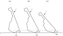
- It is a bottom view which shows the golf club of the golf club set which concerns on this invention. It is the bottom view which looked at the 3rd (a), the 6th (b), and the 9th (c) iron type golf club head from the sole surface.
- FIG. 9D is a sectional view taken along the line DD of FIG. 8A. It is the bottom view which looked at the other head concerning the present invention from the sole side.
- FIG. 1 is a side view of a reference state in which an iron type golf club head 1 is grounded to the ground G at a specified lie angle and loft angle (both not shown), and
- FIG. 2 is a view of the golf club head of FIG. FIG.
- a description will be given by taking a No. 3 iron type golf club head as an example.
- an iron type golf club head (hereinafter sometimes simply referred to as “head” or “club head”) 1 according to this embodiment includes a face surface 2 for hitting a ball, The top surface 3 that is connected to the upper edge of the face surface 2 and forms the upper surface of the head, the sole surface 4 that is connected to the lower edge of the face surface 2 and forms the bottom surface of the head, and the space between the top surface 3 and the sole surface 4 are smooth. And a back surface 6 that forms a surface opposite to the face surface 2.
- a hosel portion 9 having a shaft insertion hole 91 to which the shaft 20 is mounted is provided at the end opposite to the toe surface 5.
- the center axis Z of the insertion hole 91 coincides with the axis of the shaft 20.
- the central axis Z is included in a plane P (see FIG. 1B) perpendicular to the horizontal plane (ground G), and a predetermined lie angle and real loft angle are included.
- the state where the head 1 is placed on the ground G is defined as the reference state.
- the plane P is referred to as a reference vertical plane P.
- the direction of the line of intersection between the reference vertical plane P and the ground G is referred to as a toe-heel direction, and a direction perpendicular to the toe-heel direction and parallel to the ground G is a face-back direction. It shall be called a direction.
- the head 1 includes a face body made of a metal material as a face surface, and a head body made of a metal material different from the face plate and having the face plate disposed on the front surface.
- the head 1 may be formed by forging or casting one kind of metal material.
- the sole surface 4 of the golf club head will be described with reference to FIG. 3 is a cross-sectional view taken along line AA in FIG.
- the sole surface 4 according to the present embodiment is slightly curved in the toe-heel direction. However, as shown in FIG. 3, in the face-back direction, the sole surface 4 is straight in the toe-heel direction near the center of the sole surface 4.
- a leading surface 42 is formed on the face side and a trailing surface 43 is formed on the back side, with the boundary line 41 extending in a shape as a top.
- These are constituted by flat inclined surfaces extending from the boundary line 41 to the face side and the back side, respectively.
- the cross-sectional shape of the sole surface 4 has a mountain shape with the boundary line 41 as the top, and the boundary line 41 is a visible line.
- FIG. 4 is a schematic cross-sectional view showing the swing path of the golf club head near the ground
- FIG. 5 is a schematic cross-sectional view for explaining the gear effect.
- the sole surface 4 is shown with a cross-sectional shape of an arcuate convex surface.
- the face side end of the sole surface 4 faces the ground G (FIG. 4A), and then the top 41 is positioned at the lowest point.
- the head 1 moves away from the ground G while the back end and the ground G face each other (FIG. 4C).
- the sole surface 4 is formed as an arcuate convex surface, the face side of the sole surface 4 contacts the ground G before the top 41 contacts the ground G, as shown in FIG. . Therefore, the sole surface 4 starts to receive resistance from the ground G until the top 41 reaches the lowest point.
- a flat leading surface 42 is formed from the top 41, but this leading surface 42 does not protrude into the ground G like a convex surface. Therefore, compared with the convex surface, as shown in FIG. 4A, since the contact with the ground is reduced, the resistance with the ground G can be reduced. As a result, a decrease in swing speed can be suppressed. Then, in the sole surface 4 of the present embodiment, when the swing advances, as shown in FIG. 4B, the resistance from the ground G is concentrated at the top portion 41, so that a gear effect is generated at once. That is, as shown in FIG.
- the trailing surface 43 faces the ground G, but, like the leading surface 41, protrudes to the ground G. Therefore, the resistance received from the ground G is reduced. As a result, it is possible to prevent a reduction in swing speed when swinging out the club, and to improve the slipping performance.
- a boundary line 41 extending in the toe-heel direction is provided on the sole surface 4 as a top portion, and the leading edge that is inclined flatly toward the face side across the boundary line 41 is provided.
- a surface 42 and a trailing surface 43 inclined flatly are formed on the back side. Since these surfaces do not protrude with respect to the ground G as compared with a sole surface made of an arcuate convex surface, the resistance received from the ground G during a swing can be reduced. As a result, it is possible to prevent the swing speed from being lowered and to improve the removal performance.
- the leading surface 42 is less likely to receive resistance from the ground, the top 41 can receive resistance intensively. Therefore, as described above, the gear effect can be generated at once, and the backspin amount of the ball 100 can be increased.
- FIG. 6 is a bottom view of No. 3 (a), No. 6 (b), and No. 9 (c) iron-type golf club heads as seen from the sole surface.
- the widths L1, L2, and L3 of the leading surface 42 in the face-back direction are larger as the golf club has a smaller loft angle. That is, the width L1 of the leading surface 42 of the third iron is the largest, and the width L3 of the ninth iron is the smallest.
- the width L1 of the leading surface 42 is 40 to 60% of the width of the sole surface 4 in plan view
- the width L2 of the leading surface 42 is 30 to 50%. it can.
- the width L3 of the leading surface 42 in the width of the sole surface 4 in a plan view can be set to 20 to 40%. As described above, the following effects can be obtained by changing the width of the reading surface according to the type of ampere.
- the width of the leading surface 41 in the face-back direction is long, it takes a long time for the top 41 of the sole surface 4 to contact the ground G after the end of the sole surface 4 faces the ground G during a swing. Become. Thereby, the time until the gear effect is generated at the time of swing becomes longer.
- a long iron with a small loft angle for example, No. 3
- a short iron with a large loft angle for example, No. 9
- the widths L1, L2, and L3 of the leading surface 42 in the face-back direction are increased as the golf club has a smaller loft angle. Therefore, the gear effect can be generated at an appropriate timing by utilizing the characteristics of the long iron and the short iron as described above.
- FIG. 7 is a cross-sectional view of No. 3 (a), No. 6 (b), and No. 9 (c) iron type golf club heads.
- the moving distance of the head when the ball is in contact with a short iron is short, if the leading surface 42 is too long, the displacement of the head may vary depending on the incident angle or the head speed. Therefore, in the short iron, if the leading surface 42 is shortened, the initial shot conditions (for example, launch angle and spin amount) can be stabilized and dandruff can be prevented.
- the protrusion height of the top is made uniform in the toe-heel direction, but this may be changed as shown in FIG. 8, for example.
- 8A is a bottom view of the head viewed from the sole side
- FIG. 8B is a cross-sectional view taken along the line BB of FIG. 8A
- FIG. 8C is a cross-sectional view of FIG.
- FIG. 8D is a sectional view taken along the line C in FIG. 8A.
- the protruding height of the top 41 is the highest at the center portion in the toe-heel direction (FIG. 8C), and the ends on the toe side and the heel side are set. In the portion, the protruding height of the top portion 41 is made lower than that in the central portion (FIGS. 8B and 8D). Since the resistance described above increases at the center portion of the sole surface 4, the gear effect can be easily obtained efficiently, and the toe side and the heel side are the largest. Since the gear effect is reduced at the end of the ball, the user can hit the ball, that is, when the backspin amount is to be increased, the user hits at the center portion of the sole surface 4 and the backspin amount.
- the protrusion height here refers to the end portion on the face side and the end portion on the back side of the sole surface 4. This refers to the height from the connecting line (dotted lines in FIGS. 8B to 8D).
- the boundary line 41 of the sole surface 4 is formed in a straight line shape, but may not necessarily be a straight line and may be a line extending in the toe-heel direction. Further, as shown in FIG. 9, it can be curved so as to be convex toward the face side.
- the boundary line 41 is curved in a convex manner in this way, the width of the leading surface 42 is reduced at the center portion of the sole surface 4, and the width of the leading surface 42 is increased at the toe side and the heel side. Thereby, the following effect can be acquired.
- the face will be easier to turn right. As a result, slicing or right push-out mistakes are likely to occur.
- the toe side leading surface 42 is made slightly wider than the central portion, so that the toe side of the face surface 2 is appropriately returned and the ball trajectory is easily directed toward the center.
- the leading surface 42 on the heel side is made wider than the central portion, so that the heel side of the face surface is appropriately returned and the ball trajectory is easily directed toward the central direction.
- the leading surface 42 and the trailing surface 43 are formed in a flat surface shape, but the present invention is not limited to this.
- it may not be an arcuate convex surface over the entire sole surface as shown in FIG. 4, and the leading surface 42 and the trailing surface 43 are formed with inclined surfaces having at least a visible top as a boundary line 41.
- these surfaces do not have to be strictly flat surfaces, and may be surfaces having a radius of curvature larger than an arc passing at least the top 41 of the sole surface 4.
- the leading surface 42 and the trailing surface 43 can be formed as concave curved surfaces.
- the leading surface 42 and the trailing surface 43 may be formed on the sole surface 4 with the visible boundary line interposed therebetween. Accordingly, the configurations of the top surface, the toe surface, the face surface, and the back surface are not particularly limited, and various modes are possible as long as the iron-type golf club head is provided.
Landscapes
- Health & Medical Sciences (AREA)
- General Health & Medical Sciences (AREA)
- Physical Education & Sports Medicine (AREA)
- Golf Clubs (AREA)
Priority Applications (3)
| Application Number | Priority Date | Filing Date | Title |
|---|---|---|---|
| US14/915,010 US11266884B2 (en) | 2013-08-30 | 2014-06-09 | Iron-type golf club head and golf club set provided therewith |
| KR1020167004336A KR102263793B1 (ko) | 2013-08-30 | 2014-06-09 | 아이언형 골프 클럽 헤드 및 이것을 구비한 골프 클럽 세트 |
| CN201480046683.2A CN105492087B (zh) | 2013-08-30 | 2014-06-09 | 高尔夫球杆套件 |
Applications Claiming Priority (2)
| Application Number | Priority Date | Filing Date | Title |
|---|---|---|---|
| JP2013180569A JP6255190B2 (ja) | 2013-08-30 | 2013-08-30 | アイアン型ゴルフクラブヘッド、及びこれを備えたゴルフクラブセット |
| JP2013-180569 | 2013-08-30 |
Publications (1)
| Publication Number | Publication Date |
|---|---|
| WO2015029538A1 true WO2015029538A1 (ja) | 2015-03-05 |
Family
ID=52586117
Family Applications (1)
| Application Number | Title | Priority Date | Filing Date |
|---|---|---|---|
| PCT/JP2014/065206 Ceased WO2015029538A1 (ja) | 2013-08-30 | 2014-06-09 | アイアン型ゴルフクラブヘッド、及びこれを備えたゴルフクラブセット |
Country Status (5)
| Country | Link |
|---|---|
| US (1) | US11266884B2 (enExample) |
| JP (1) | JP6255190B2 (enExample) |
| KR (1) | KR102263793B1 (enExample) |
| CN (1) | CN105492087B (enExample) |
| WO (1) | WO2015029538A1 (enExample) |
Cited By (1)
| Publication number | Priority date | Publication date | Assignee | Title |
|---|---|---|---|---|
| CN107174807A (zh) * | 2016-03-11 | 2017-09-19 | 邓禄普体育用品株式会社 | 铁型高尔夫球杆组 |
Families Citing this family (4)
| Publication number | Priority date | Publication date | Assignee | Title |
|---|---|---|---|---|
| JP6711038B2 (ja) * | 2016-03-11 | 2020-06-17 | 住友ゴム工業株式会社 | ゴルフクラブ及びゴルフクラブセット |
| JP6711039B2 (ja) * | 2016-03-11 | 2020-06-17 | 住友ゴム工業株式会社 | アイアン型ゴルフクラブセット |
| JP7615699B2 (ja) * | 2021-01-18 | 2025-01-17 | 住友ゴム工業株式会社 | ゴルフクラブヘッド及びゴルフクラブ |
| JP2024008174A (ja) * | 2022-07-07 | 2024-01-19 | 住友ゴム工業株式会社 | ゴルフクラブヘッド |
Citations (9)
| Publication number | Priority date | Publication date | Assignee | Title |
|---|---|---|---|---|
| JPS6480378A (en) * | 1987-09-22 | 1989-03-27 | Endo Seisakusho Kk | Golf club |
| JPH0263483A (ja) * | 1988-08-31 | 1990-03-02 | Maruman Golf Corp | アイアンクラブ |
| JPH0731696A (ja) * | 1993-07-06 | 1995-02-03 | Lisco Inc | 4方向にダイヤ形カットをしたソールを有するゴルフクラブヘッド |
| JP2001252380A (ja) * | 2000-01-21 | 2001-09-18 | Acushnet Co | ゴルフクラブのソール構造 |
| JP2005073780A (ja) * | 2003-08-28 | 2005-03-24 | Sumitomo Rubber Ind Ltd | アイアンゴルフクラブ及びアイアンゴルフクラブセット |
| JP2005211560A (ja) * | 2004-02-02 | 2005-08-11 | Yokohama Rubber Co Ltd:The | ゴルフクラブヘッド |
| JP2008035984A (ja) * | 2006-08-03 | 2008-02-21 | Sri Sports Ltd | アイアン型ゴルフクラブヘッド及びこれを備えたアイアンゴルフクラブ |
| JP2008194335A (ja) * | 2007-02-15 | 2008-08-28 | Sri Sports Ltd | アイアン型ゴルフクラブヘッド |
| JP2013000161A (ja) * | 2011-06-13 | 2013-01-07 | Mizuno Corp | アイアンゴルフクラブヘッドおよびアイアンゴルフクラブ |
Family Cites Families (46)
| Publication number | Priority date | Publication date | Assignee | Title |
|---|---|---|---|---|
| US3088736A (en) * | 1959-05-05 | 1963-05-07 | Nicholas R Mospan | Golf club head and shaft |
| US3897065A (en) * | 1974-01-31 | 1975-07-29 | Karsten Solheim | Golf club head with improved sole and toe portions |
| US4867457A (en) * | 1988-04-27 | 1989-09-19 | Puttru, Inc. | Golf putter head |
| US4938470A (en) * | 1988-12-23 | 1990-07-03 | Antonious A J | Perimeter weighted iron type golf club head with upper alignment and sighting area and complementary weighting system |
| US5193805A (en) * | 1991-08-23 | 1993-03-16 | Karsten Manufacturing Corporation | Weighted cavity back golf club set |
| US5471601A (en) * | 1992-06-17 | 1995-11-28 | Intel Corporation | Memory device and method for avoiding live lock of a DRAM with cache |
| US5301944A (en) * | 1993-01-14 | 1994-04-12 | Koehler Terry B | Golf club head with improved sole |
| US5429353A (en) * | 1993-07-30 | 1995-07-04 | Acushnet Company | Golf club irons and method of manufacture of iron sets |
| US5549296A (en) * | 1995-03-10 | 1996-08-27 | Acushnet Company | Golf club sole configuration |
| US5813919A (en) * | 1996-06-28 | 1998-09-29 | Cobra Golf, Inc. | Dual sole golf club head |
| US6093113A (en) * | 1998-02-03 | 2000-07-25 | D. W. Golf Club, Inc. | Golf club head with improved sole configuration |
| US5971866A (en) * | 1999-01-26 | 1999-10-26 | Adams Golf, Inc. | Wedge type golf club tri-level sole configuration |
| US6482104B1 (en) * | 1999-04-05 | 2002-11-19 | Acushnet Company | Set of golf clubs |
| US6251029B1 (en) * | 1999-08-20 | 2001-06-26 | Play Sports Company Pty Ltd | Golf club head |
| DE60120349T2 (de) * | 2000-10-16 | 2007-05-31 | Mizuno Corp. | Eisengolfschläger und golfschlägerset |
| US6569029B1 (en) * | 2001-08-23 | 2003-05-27 | Edward Hamburger | Golf club head having replaceable bounce angle portions |
| US6695714B1 (en) * | 2003-03-10 | 2004-02-24 | Karsten Manufacturing Corporation | Iron-Type golf club head with beveled sole |
| JP4525302B2 (ja) | 2004-11-09 | 2010-08-18 | 横浜ゴム株式会社 | ゴルフクラブ |
| US8523705B2 (en) * | 2005-04-21 | 2013-09-03 | Cobra Golf Incorporated | Golf club head |
| US7824277B2 (en) * | 2005-12-23 | 2010-11-02 | Acushnet Company | Metal wood club |
| JP4779643B2 (ja) * | 2005-12-27 | 2011-09-28 | ブリヂストンスポーツ株式会社 | アイアンセット |
| US9352198B2 (en) * | 2006-07-21 | 2016-05-31 | Cobra Golf Incorporated | Multi-material golf club head |
| JP4965385B2 (ja) * | 2006-07-21 | 2012-07-04 | コブラ ゴルフ インコーポレイテッド | 多材ゴルフクラブヘッド |
| JP5172438B2 (ja) * | 2007-04-09 | 2013-03-27 | 株式会社遠藤製作所 | アイアンゴルフクラブ |
| US9079080B2 (en) * | 2007-07-25 | 2015-07-14 | Karsten Manufacturing Corporation | Club head sets with varying characteristics and related methods |
| US8753230B2 (en) * | 2007-07-25 | 2014-06-17 | Karsten Manufacturing Corporation | Club head sets with varying characteristics |
| USD581000S1 (en) * | 2007-11-21 | 2008-11-18 | Karsten Manufacturing Corporation | Golf iron head |
| US20090291772A1 (en) * | 2008-05-21 | 2009-11-26 | Robert Boyd | Golf club and golf club head with interchangeable body component |
| US8083607B2 (en) * | 2008-08-12 | 2011-12-27 | Cobra Golf Incorporated | Iron-type golf clubs |
| US7614962B1 (en) * | 2008-08-12 | 2009-11-10 | Acushnet Company | Set of iron-type golf clubs having a progressive sole configuration |
| US9079081B2 (en) * | 2009-07-22 | 2015-07-14 | Bridgestone Sports Co., Ltd. | Iron head |
| US9561413B2 (en) * | 2009-12-23 | 2017-02-07 | Taylor Made Golf Company, Inc. | Golf club head |
| US8202174B2 (en) * | 2010-02-22 | 2012-06-19 | Cobra Golf Incorporated | Golf club |
| JP5936301B2 (ja) * | 2010-12-15 | 2016-06-22 | ダンロップスポーツ株式会社 | アイアンゴルフクラブセット |
| USD643492S1 (en) * | 2011-03-15 | 2011-08-16 | Karsten Manufacturing Corporation | Golf club head |
| US20130165251A1 (en) * | 2011-12-27 | 2013-06-27 | Douglas C. Jorgensen | Golf club with reversible sole |
| US9044653B2 (en) * | 2012-06-08 | 2015-06-02 | Taylor Made Golf Company, Inc. | Iron type golf club head |
| US20140073447A1 (en) * | 2012-09-10 | 2014-03-13 | Charles E. Golden | Golf club iron set producing flight having consistent angle of descent |
| US20140274441A1 (en) * | 2013-03-13 | 2014-09-18 | Karsten Manufacturing Corporation | Variable bounce height club heads and related methods |
| US9199143B1 (en) * | 2014-08-25 | 2015-12-01 | Parsons Xtreme Golf, LLC | Golf club heads and methods to manufacture golf club heads |
| US9381410B2 (en) * | 2014-05-07 | 2016-07-05 | Acushnet Company | Metal wood club |
| GB2540504B (en) * | 2014-05-15 | 2020-12-23 | Karsten Mfg Corp | Club heads having reinforced club head faces and related methods |
| JP6711038B2 (ja) * | 2016-03-11 | 2020-06-17 | 住友ゴム工業株式会社 | ゴルフクラブ及びゴルフクラブセット |
| JP6790387B2 (ja) * | 2016-03-11 | 2020-11-25 | 住友ゴム工業株式会社 | アイアン型ゴルフクラブセット |
| JP6711039B2 (ja) * | 2016-03-11 | 2020-06-17 | 住友ゴム工業株式会社 | アイアン型ゴルフクラブセット |
| JP7014424B2 (ja) * | 2018-10-24 | 2022-02-01 | 北川工業株式会社 | コネクタ固定具 |
-
2013
- 2013-08-30 JP JP2013180569A patent/JP6255190B2/ja active Active
-
2014
- 2014-06-09 US US14/915,010 patent/US11266884B2/en active Active
- 2014-06-09 KR KR1020167004336A patent/KR102263793B1/ko active Active
- 2014-06-09 CN CN201480046683.2A patent/CN105492087B/zh active Active
- 2014-06-09 WO PCT/JP2014/065206 patent/WO2015029538A1/ja not_active Ceased
Patent Citations (9)
| Publication number | Priority date | Publication date | Assignee | Title |
|---|---|---|---|---|
| JPS6480378A (en) * | 1987-09-22 | 1989-03-27 | Endo Seisakusho Kk | Golf club |
| JPH0263483A (ja) * | 1988-08-31 | 1990-03-02 | Maruman Golf Corp | アイアンクラブ |
| JPH0731696A (ja) * | 1993-07-06 | 1995-02-03 | Lisco Inc | 4方向にダイヤ形カットをしたソールを有するゴルフクラブヘッド |
| JP2001252380A (ja) * | 2000-01-21 | 2001-09-18 | Acushnet Co | ゴルフクラブのソール構造 |
| JP2005073780A (ja) * | 2003-08-28 | 2005-03-24 | Sumitomo Rubber Ind Ltd | アイアンゴルフクラブ及びアイアンゴルフクラブセット |
| JP2005211560A (ja) * | 2004-02-02 | 2005-08-11 | Yokohama Rubber Co Ltd:The | ゴルフクラブヘッド |
| JP2008035984A (ja) * | 2006-08-03 | 2008-02-21 | Sri Sports Ltd | アイアン型ゴルフクラブヘッド及びこれを備えたアイアンゴルフクラブ |
| JP2008194335A (ja) * | 2007-02-15 | 2008-08-28 | Sri Sports Ltd | アイアン型ゴルフクラブヘッド |
| JP2013000161A (ja) * | 2011-06-13 | 2013-01-07 | Mizuno Corp | アイアンゴルフクラブヘッドおよびアイアンゴルフクラブ |
Cited By (1)
| Publication number | Priority date | Publication date | Assignee | Title |
|---|---|---|---|---|
| CN107174807A (zh) * | 2016-03-11 | 2017-09-19 | 邓禄普体育用品株式会社 | 铁型高尔夫球杆组 |
Also Published As
| Publication number | Publication date |
|---|---|
| US20160199704A1 (en) | 2016-07-14 |
| JP6255190B2 (ja) | 2017-12-27 |
| US11266884B2 (en) | 2022-03-08 |
| KR20160048075A (ko) | 2016-05-03 |
| KR102263793B1 (ko) | 2021-06-10 |
| JP2015047305A (ja) | 2015-03-16 |
| CN105492087B (zh) | 2018-03-13 |
| CN105492087A (zh) | 2016-04-13 |
Similar Documents
| Publication | Publication Date | Title |
|---|---|---|
| JP3984989B2 (ja) | 複数のバルジ半径をもったフェースを有するゴルフクラブヘッド | |
| US8021246B2 (en) | Iron golf club heads and golf club sets with variable weight distribution | |
| US8579718B2 (en) | Putter head | |
| JP6255190B2 (ja) | アイアン型ゴルフクラブヘッド、及びこれを備えたゴルフクラブセット | |
| JP2007136069A (ja) | ゴルフクラブヘッド | |
| US9878219B2 (en) | Golf club and golf club set | |
| JP5785893B2 (ja) | ゴルフクラブヘッド、及びゴルフクラブ | |
| US10105580B2 (en) | Iron type golf club set | |
| JP4352461B2 (ja) | ゴルフクラブ | |
| US9956461B2 (en) | Iron type golf club set | |
| JP2015047305A5 (enExample) | ||
| JP2005073780A (ja) | アイアンゴルフクラブ及びアイアンゴルフクラブセット | |
| JP2005253562A (ja) | アイアンゴルフクラブヘッド及びそれを用いたアイアンゴルフクラブ | |
| JP6219762B2 (ja) | ゴルフクラブヘッド及び当該ゴルフクラブヘッドを備えるゴルフクラブ | |
| JP2005168998A (ja) | ウッド型ゴルフクラブヘッド及びこれを備えたウッド型ゴルフクラブ | |
| JP5427812B2 (ja) | ゴルフクラブ | |
| JP2012105961A (ja) | ゴルフクラブヘッド | |
| JP2001037920A (ja) | アイアンゴルフクラブセット | |
| KR20110008882U (ko) | 골프용 퍼터 | |
| JPH0557037A (ja) | ゴルフクラブヘツド | |
| KR20110007802U (ko) | 골프 퍼터 |
Legal Events
| Date | Code | Title | Description |
|---|---|---|---|
| WWE | Wipo information: entry into national phase |
Ref document number: 201480046683.2 Country of ref document: CN |
|
| 121 | Ep: the epo has been informed by wipo that ep was designated in this application |
Ref document number: 14840466 Country of ref document: EP Kind code of ref document: A1 |
|
| ENP | Entry into the national phase |
Ref document number: 20167004336 Country of ref document: KR Kind code of ref document: A |
|
| WWE | Wipo information: entry into national phase |
Ref document number: 14915010 Country of ref document: US |
|
| NENP | Non-entry into the national phase |
Ref country code: DE |
|
| 122 | Ep: pct application non-entry in european phase |
Ref document number: 14840466 Country of ref document: EP Kind code of ref document: A1 |