WO2015025961A1 - バナジウム電解質、その製造方法及びバナジウムレドックス電池 - Google Patents
バナジウム電解質、その製造方法及びバナジウムレドックス電池 Download PDFInfo
- Publication number
- WO2015025961A1 WO2015025961A1 PCT/JP2014/072053 JP2014072053W WO2015025961A1 WO 2015025961 A1 WO2015025961 A1 WO 2015025961A1 JP 2014072053 W JP2014072053 W JP 2014072053W WO 2015025961 A1 WO2015025961 A1 WO 2015025961A1
- Authority
- WO
- WIPO (PCT)
- Prior art keywords
- vanadium
- electrolyte
- positive electrode
- negative electrode
- paste
- Prior art date
- Legal status (The legal status is an assumption and is not a legal conclusion. Google has not performed a legal analysis and makes no representation as to the accuracy of the status listed.)
- Ceased
Links
Images




Classifications
-
- H—ELECTRICITY
- H01—ELECTRIC ELEMENTS
- H01M—PROCESSES OR MEANS, e.g. BATTERIES, FOR THE DIRECT CONVERSION OF CHEMICAL ENERGY INTO ELECTRICAL ENERGY
- H01M8/00—Fuel cells; Manufacture thereof
- H01M8/18—Regenerative fuel cells, e.g. redox flow batteries or secondary fuel cells
- H01M8/184—Regeneration by electrochemical means
- H01M8/188—Regeneration by electrochemical means by recharging of redox couples containing fluids; Redox flow type batteries
-
- H—ELECTRICITY
- H01—ELECTRIC ELEMENTS
- H01M—PROCESSES OR MEANS, e.g. BATTERIES, FOR THE DIRECT CONVERSION OF CHEMICAL ENERGY INTO ELECTRICAL ENERGY
- H01M10/00—Secondary cells; Manufacture thereof
- H01M10/36—Accumulators not provided for in groups H01M10/05-H01M10/34
-
- H—ELECTRICITY
- H01—ELECTRIC ELEMENTS
- H01M—PROCESSES OR MEANS, e.g. BATTERIES, FOR THE DIRECT CONVERSION OF CHEMICAL ENERGY INTO ELECTRICAL ENERGY
- H01M10/00—Secondary cells; Manufacture thereof
- H01M10/36—Accumulators not provided for in groups H01M10/05-H01M10/34
- H01M10/38—Construction or manufacture
-
- Y—GENERAL TAGGING OF NEW TECHNOLOGICAL DEVELOPMENTS; GENERAL TAGGING OF CROSS-SECTIONAL TECHNOLOGIES SPANNING OVER SEVERAL SECTIONS OF THE IPC; TECHNICAL SUBJECTS COVERED BY FORMER USPC CROSS-REFERENCE ART COLLECTIONS [XRACs] AND DIGESTS
- Y02—TECHNOLOGIES OR APPLICATIONS FOR MITIGATION OR ADAPTATION AGAINST CLIMATE CHANGE
- Y02E—REDUCTION OF GREENHOUSE GAS [GHG] EMISSIONS, RELATED TO ENERGY GENERATION, TRANSMISSION OR DISTRIBUTION
- Y02E60/00—Enabling technologies; Technologies with a potential or indirect contribution to GHG emissions mitigation
- Y02E60/10—Energy storage using batteries
-
- Y—GENERAL TAGGING OF NEW TECHNOLOGICAL DEVELOPMENTS; GENERAL TAGGING OF CROSS-SECTIONAL TECHNOLOGIES SPANNING OVER SEVERAL SECTIONS OF THE IPC; TECHNICAL SUBJECTS COVERED BY FORMER USPC CROSS-REFERENCE ART COLLECTIONS [XRACs] AND DIGESTS
- Y02—TECHNOLOGIES OR APPLICATIONS FOR MITIGATION OR ADAPTATION AGAINST CLIMATE CHANGE
- Y02E—REDUCTION OF GREENHOUSE GAS [GHG] EMISSIONS, RELATED TO ENERGY GENERATION, TRANSMISSION OR DISTRIBUTION
- Y02E60/00—Enabling technologies; Technologies with a potential or indirect contribution to GHG emissions mitigation
- Y02E60/30—Hydrogen technology
- Y02E60/50—Fuel cells
-
- Y—GENERAL TAGGING OF NEW TECHNOLOGICAL DEVELOPMENTS; GENERAL TAGGING OF CROSS-SECTIONAL TECHNOLOGIES SPANNING OVER SEVERAL SECTIONS OF THE IPC; TECHNICAL SUBJECTS COVERED BY FORMER USPC CROSS-REFERENCE ART COLLECTIONS [XRACs] AND DIGESTS
- Y02—TECHNOLOGIES OR APPLICATIONS FOR MITIGATION OR ADAPTATION AGAINST CLIMATE CHANGE
- Y02P—CLIMATE CHANGE MITIGATION TECHNOLOGIES IN THE PRODUCTION OR PROCESSING OF GOODS
- Y02P70/00—Climate change mitigation technologies in the production process for final industrial or consumer products
- Y02P70/50—Manufacturing or production processes characterised by the final manufactured product
Definitions
- the present invention relates to a vanadium electrolyte, a manufacturing method thereof, and a vanadium redox battery. More specifically, the present invention relates to a vanadium electrolyte, a vanadium redox battery, and the like that have a high storage capacity and a high energy density, are difficult to increase the resistance of the electrolyte, and are less likely to decrease ionic conductivity.
- Secondary batteries are attracting attention as an energy storage source with a low environmental load that can repeatedly charge and discharge electricity.
- lead storage batteries, sodium sulfur batteries, redox flow batteries, and the like are known.
- redox flow batteries using vanadium electrolyte operate at room temperature, and the active material is liquid and can be stored in an external tank, so it is easy to increase in size and regenerate compared to electrolytes of other secondary batteries. There are advantages such as easy and long life.
- the redox flow battery uses an electrolytic cell divided into a positive electrode and a negative electrode by an ion exchange membrane. Vanadium ion solutions having different valences are placed in each electrolytic cell, and vanadium ions are circulated when the vanadium ion solution circulates in the electrolytic cell. It is a circulation type vanadium redox battery in which charge and discharge are performed by changing the valence of ions.
- the chemical reaction by charging / discharging is as the following formula, and charging / discharging reaction of Formula (1) occurs in the positive electrode, and charging / discharging reaction of Formula (2) occurs in the negative electrode. In Expressions (1) and (2), the right side moves from the right side to the left side during discharging, and the left side to the right side during charging.
- the vanadium electrolyte used in the redox flow battery is usually prepared by dissolving vanadium oxide sulfate (VOSO 4 ⁇ nH 2 O) in a sulfuric acid aqueous solution to prepare a tetravalent vanadium ion solution, and the vanadium ion solution is used in each electrolytic cell. Vanadium ion solutions having different valences are obtained by electrolysis while circulating.
- VOSO 4 ⁇ nH 2 O vanadium oxide sulfate
- a pentavalent (VO 2 + ) vanadium ion solution which is a positive electrode active material
- a tetravalent vanadium ion solution is prepared on the negative electrode side
- a divalent (V 2+ ) vanadium ion solution which is a negative electrode active material, is prepared by a reduction reaction.
- Patent Document 1 precipitation of a vanadium compound can be prevented by adding a protective colloid agent, an oxo acid, a complexing agent, or the like to an aqueous sulfuric acid solution containing vanadium ions and / or vanadyl ions.
- a protective colloid agent for example, an oxo acid, a complexing agent, or the like.
- the redox flow battery 100 includes an electrolytic cell 101 separated into a positive electrode cell 101A and a negative electrode cell 101B by a diaphragm 104.
- the positive electrode cell 101A and the negative electrode cell 101B have a positive electrode 105 and a negative electrode 106, respectively.
- a positive electrode electrolyte tank 102 for supplying and discharging a positive electrode electrolyte is connected to the positive electrode cell 101A via pipes 107 and 108, and negative electrode electrolysis for supplying and discharging a negative electrode electrolyte to the negative electrode cell 101B.
- a liquid tank 103 is connected via pipes 110 and 111.
- the positive electrode electrolyte is a mixed solution of pentavalent and tetravalent vanadium ions
- the negative electrode electrolyte is a mixed solution of divalent and trivalent vanadium ions
- these electrolytes are circulated by pumps 109 and 112, respectively.
- the positive electrode 105 and the negative electrode 106 are configured to perform charge / discharge represented by the above formulas (1) and (2).
- the storage capacity of the conventional redox flow battery described above is determined by the amount of vanadium dissolved in the electrolytic solution, and the amount of vanadium is proportional to the volume of the electrolytic solution and the concentration of vanadium ions in the electrolytic solution. Therefore, the storage capacity increases as the total amount of vanadium electrolyte increases, and increases as the vanadium ion concentration in the vanadium electrolyte increases. The energy density also increases as the vanadium ion concentration in the vanadium electrolyte increases.
- a conventional redox flow battery using a vanadium electrolyte as an electrolyte has an electrolyte concentration of about 1 to 2 mol / L, and it cannot be said that the storage capacity and energy density are high.
- Patent Document 3 a high concentration vanadium electrolyte solution that prevented the generation of sludge and the like, which had been a problem in the past, and used the high concentration vanadium electrolyte solution.
- the proposed vanadium redox battery The proposed vanadium redox battery.
- Patent Document 4 for the purpose of obtaining a secondary battery having a high energy density while having a high storage capacity, a first vanadium compound for a negative electrode, a second vanadium compound for a positive electrode, A solid vanadium secondary battery including a separator sandwiched between first and second vanadium compounds has been proposed.
- vanadium redox battery has not yet sufficient storage capacity and energy density as compared with the lithium secondary battery, and it is required to increase them. Further, there is a demand for an electrolyte that has a high power storage capacity and a high energy density, and that does not easily increase the resistance of the electrolyte and that does not easily decrease ionic conductivity.
- the present invention has been made in order to meet the above-mentioned demands, and its object is to have a high storage capacity and high energy density, and it is difficult to increase the resistance of the electrolyte and to reduce the ionic conductivity, and its vanadium electrolyte. It is to provide a manufacturing method. Moreover, it is providing the vanadium redox battery provided with the vanadium electrolyte.
- a vanadium electrolyte according to the present invention for solving the above-mentioned problems includes vanadium ions in a concentration range of 3.5 mol / L or more and 6.5 mol / L or less, sulfate ions, and conductive powder, It is characterized by being a foamed paste electrolyte.
- the paste electrolyte since it is a paste-like electrolyte containing vanadium ions, sulfate ions and conductive powder at the above concentrations, it has a high storage capacity and a high energy density.
- the paste electrolyte since the paste electrolyte is defoamed, bubbles (air bubbles) contained in the paste electrolyte can be removed. As a result, it is possible to suppress a decrease in conductive resistance due to the presence of bubbles and to conduct ions. The fall of property can also be suppressed.
- the paste electrolyte may contain phosphoric acid.
- the paste-like electrolyte contains phosphoric acid
- the presence of the phosphoric acid makes it easier to ionize vanadium ions and further suppress the generation of precipitates such as oxides.
- it can be preferably used as a vanadium electrolyte for a negative electrode.
- a method for producing a vanadium electrolyte according to the present invention for solving the above problems is a method for producing the vanadium electrolyte according to the present invention, and has a concentration of 3.5 mol / L or more and 6.5 mol / L or less.
- a conductive powder is kneaded into a paste containing vanadium oxosulfate containing a range of vanadium ions and sulfate ions, and then defoamed.
- the paste state since the conductive powder is kneaded into the paste containing vanadium oxosulfate (VOSO 4 ) containing vanadium ions having the above-mentioned concentration and sulfate ions, the paste state has a high storage capacity and a high energy density. It can be an electrolyte.
- the paste electrolyte since the paste electrolyte is defoamed, bubbles (air bubbles) contained in the paste electrolyte can be removed, and as a result, a decrease in conductive resistance due to the presence of bubbles can be suppressed and ion conduction can be suppressed.
- the vanadium electrolyte which can also suppress a fall of property can be manufactured.
- a vanadium redox battery according to the present invention for solving the above-described problems includes a positive electrode, a vanadium electrolyte for positive electrode formed by oxidizing and electrolyzing the vanadium electrolyte according to the present invention, a diaphragm, and the vanadium according to the present invention. It includes at least a single cell structure in which a vanadium electrolyte for a negative electrode obtained by subjecting an electrolyte to reduction electrolysis and a negative electrode are arranged in that order.
- a vanadium redox battery including a vanadium electrolyte that has a high storage capacity and a high energy density, is difficult to increase the resistance of the electrolyte, and is less likely to decrease ionic conductivity.
- a vanadium electrolyte that has a high storage capacity and a high energy density, does not easily increase the resistance of the electrolyte, and does not easily decrease ionic conductivity, a manufacturing method thereof, and a vanadium redox battery.
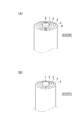
- (A) is an example in which a carbon rod is arranged at the center and a positive electrode is brought into contact with the carbon rod
- (B) is an example in which a positive electrode rod is arranged at the center.
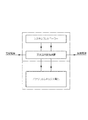
- It is a system block diagram of a vanadium redox battery. It is a schematic diagram which shows the manufacturing method of the electrolyte solution for conventional positive electrodes, and the electrolyte solution for negative electrodes. It is a schematic diagram explaining the principle of the conventional common redox flow battery.
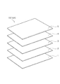
- the vanadium redox batteries 10 and 20 include a positive electrode 1, a positive electrode vanadium electrolyte 2, a diaphragm 3, a negative electrode vanadium electrolyte 4, and a negative electrode 5, in that order. Including at least a single cell structure.
- the vanadium redox batteries 10 and 20 have a vanadium electrolyte 2 for a positive electrode and a vanadium electrolyte 4 for a negative electrode, both of which are 3.5 mol / L or more and 6.5 mol / L or less. It is a paste electrolyte that contains vanadium ions in a concentration range and is defoamed. Vanadium redox batteries 10 and 20 including vanadium electrolytes 2 and 4 made of such a paste-like electrolyte have a high storage capacity and a high energy density. Further, since the paste electrolyte is defoamed, bubbles (air bubbles) contained in the paste electrolyte can be removed. As a result, the vanadium redox batteries 10 and 20 have a conductive resistance due to the presence of bubbles. While a fall can be suppressed, a fall of ion conductivity can also be suppressed.
- the vanadium electrolyte for positive electrode 2 and the vanadium electrolyte for negative electrode 4 are provided with a diaphragm 3 interposed therebetween.
- Each of the vanadium electrolytes 2 and 4 contains vanadium ions in a high concentration range of 3.5 mol / L or more and 6.5 mol / L or less, sulfate ions, and conductive powder.
- vanadium electrolytes 2 and 4 contain vanadium ions in a high concentration range, a high storage capacity and a high energy density can be realized.
- the vanadium electrolytes 2 and 4 are aqueous paste electrolytes containing vanadium oxosulfate (VOSO 4 ), sulfate ions, and water. All of vanadium oxosulfate may be dissolved in the electrolyte, or a part thereof may be dissolved and a part thereof may be present as vanadium oxosulfate.
- VOSO 4 vanadium oxosulfate
- All of vanadium oxosulfate may be dissolved in the electrolyte, or a part thereof may be dissolved and a part thereof may be present as vanadium oxosulfate.
- Examples of production of vanadium electrolytes 2 and 4 are as follows: (1) First, considering the amount of sulfuric acid or phosphoric acid added later, the vanadium ion concentration in the final vanadium electrolytes 2 and 4 is 3.5 mol / L or more. A vanadium oxosulfate solution adjusted to a concentration range of 6.5 mol / L or less is prepared. The prepared vanadium oxosulfate solution contains vanadium oxosulfate and water. The water content is adjusted in consideration of the vanadium ion concentration in the final vanadium electrolytes 2 and 4 and the viscosity of the final paste-like vanadium electrolytes 2 and 4.
- the water content is relatively low when the vanadium ion concentration is high, and relatively high when the vanadium ion concentration is low.
- the final paste-like vanadium electrolytes 2 and 4 have a high viscosity and are difficult to flow, kneading and defoaming are difficult to perform. Therefore, it is preferable to relatively increase the amount of water.
- conductive powder is added to the prepared vanadium oxosulfate solution.
- various materials can be used as long as they are acid-resistant electrically conductive powders. Specifically, carbon materials such as graphite (graphite) and graphene can be preferably mentioned.
- the size of the conductive powder may be, for example, a conductive powder having a sieve of 400 mesh or more, or an average particle size within a range of, for example, about 300 ⁇ m or more and 700 ⁇ m or less. Can be selected and used.
- the blending ratio of the conductive powder varies depending on the type, but when a carbon material is used, it is within the range of 5% by volume or more and 30% by volume or less with respect to the total capacity of the vanadium electrolytes 2 and 4 finally obtained. If it is.
- the mixture obtained by blending the carbon material within this range becomes a conductive paste having good conductivity by kneading thereafter. Since the conductive paste obtained by the kneading treatment is imparted with conductivity, vanadium ions can be easily oxidized or reduced during the subsequent electrolytic treatment.
- the standard of conductivity at this stage is preferably within a range of about 1.5 ⁇ or less, and it is preferable to blend the conductive powder with this level as a standard.
- the entire amount of the conductive powder may be added at this stage before the electrolytic treatment, or a part thereof may be added at this stage and the rest may be added after the electrolytic treatment.
- the fluidity of the mixture obtained by blending the conductive powder with the vanadium oxosulfate solution is not significantly lowered, and subsequent handling is not hindered.
- the flowability of the mixture is remarkably lowered by adding the whole amount, and subsequent handling is hindered.
- it can be added within the range of 5% by volume or more and 15% by volume or less with respect to the total capacity.
- a mixture obtained by adding conductive powder to the vanadium oxosulfate solution is kneaded with a kneading apparatus.
- a conductive paste in which the vanadium oxosulfate solution and the conductive powder are uniformly mixed is obtained.
- the kneading apparatus is not particularly limited, and various types can be used.
- the defoaming process is a process for removing bubbles (air bubbles) contained in the conductive paste.
- defoaming may be performed at the same time as kneading using a kneading apparatus with a depressurizing apparatus, or the conductive paste after kneading may be thrown into the depressurizing apparatus for defoaming.
- the pressure is preferably reduced to a pressure of about 130 Pa (1 Torr) or more and 1300 Pa (10 Torr) or less.
- the bubbles contained in the conductive paste can be removed by reducing the pressure within the above range.
- the defoaming treatment can remove bubbles (air bubbles) contained in the conductive paste, and as a result, it is possible to suppress a decrease in the conductive resistance of the conductive paste due to the presence of bubbles, and also to reduce the ionic conductivity of the conductive paste. Can be suppressed.
- it is preferable to perform a defoaming process in this step you may perform it later instead of performing at this step.
- the defoaming treatment by reducing pressure can remove bubbles (air bubbles) contained in the conductive paste, and can substantially reduce the oxygen content contained in the conductive paste.
- the vanadium electrolyte can avoid the disadvantages due to the presence of oxygen.
- the vanadium electrolyte for negative electrode has an advantage that since the oxygen contained in the vanadium electrolyte is small, oxidation due to the oxygen becomes small and the reduction reaction easily proceeds.
- the conductive paste is subjected to electrolytic treatment.
- the obtained conductive paste is divided into two parts, one is put in an oxidation electrolysis apparatus, and the other is put in a reduction electric apparatus.
- Oxidation electrolysis of the conductive paste put in the oxidation electrolysis apparatus can obtain the vanadium electrolyte 2 for the positive electrode
- reduction electrolysis of the conductive paste put in the reduction electrolysis apparatus obtains the vanadium electrolyte 4 for the negative electrode. be able to.
- Electrolytic treatment is preferably performed in an inert atmosphere such as nitrogen.
- the inert atmosphere can be realized by introducing an inert gas such as nitrogen into the sealed electrolysis apparatus as much as possible.
- the conductive paste is electrolyzed while being mechanically stirred in an electrolysis apparatus in an inert atmosphere.
- the electrolytic treatment can be performed by various methods. For example, (i) oxidation of vanadium ions contained in the conductive paste (V 4+ ⁇ V 5+ ) may be carried out independently with the conductive paste as the anode side and a dummy electrolyte such as sodium sulfate as the cathode side, ii) Reduction of vanadium ions contained in the conductive paste (V 4+ ⁇ V 2+ , V 3+ ) may be carried out independently with the conductive paste as the cathode side and the dummy electrolyte such as sodium sulfate as the anode side, iii) The conductive paste may be put on both the anode side and the cathode side, and vanadium ions contained in both may be oxidized (V 4+ ⁇ V 5+ ) and reduced (V 4+ ⁇ V 2+ , V 3+ ), (iv) First, with the conductive paste as the cathode side and the dummy electro
- the electrolysis of the dummy electrolyte is preferably performed while being circulated.
- a lead electrode or an acid-resistant metal platinum electrode or platinum-coated titanium electrode
- the method (iv) can be mentioned.
- vanadium ions contained in the conductive paste are first reduced to some extent (V 4+ ⁇ V 3+ ) using the conductive paste as the negative electrode side and a dummy electrolyte such as dilute sulfuric acid or sodium sulfate as the positive electrode side.
- the applied voltage between the positive electrode and the negative electrode at this time is about 1.5 V or more and 1.7 V or less, preferably about 1.6 V.
- the current density flowing at this time 2 mA / cm 2 or more, preferably in the range of 8 mA / cm 2 or less, 3mA / cm 2 or more, and more preferably in a range of 5 mA / cm 2 or less .
- “Reducing to some extent” is preferably reduced until reaching a range of 200 mV or more and 150 mV or less as a standard of the potential (ORP) measured by the electrode potential measuring device.
- the electrode potential measuring instrument is a measuring instrument that can measure the electrode potential at regular time intervals or in real time and uses a silver-silver chloride electrode as a reference electrode.
- an electrolyte such as dilute sulfuric acid or sodium sulfate can be used, and the potential of the dummy electrolyte is preferably managed at about 1000 mV or less.
- the vanadium ions contained in the conductive paste are reduced to some extent (V 4+ ⁇ V 3+ ). Thereafter, the dummy electrolyte solution on the anode side is drained, another conductive paste is inserted instead, and electrolysis is performed in the same manner to reduce the vanadium ions contained in both (V 3+ ⁇ V 2+ ) and oxidation (V 4+ ⁇ ). V5 + ).
- the applied voltage between the positive electrode and the negative electrode is about 1.5V to 1.7V, preferably about 1.6V.
- the current density flowing at this time 4mA / cm 2 or more, preferably in the range of 12 mA / cm 2 or less, 5 mA / cm 2 or more, and more preferably in a range of 10 mA / cm 2 or less .
- an additive such as sulfuric acid or hydrochloric acid to the anode-side conductive paste when the anode potential (ORP) reaches the range of 800 mV to 900 mV.
- Sulfuric acid can improve the ionic conductivity and electronic conductivity of the obtained vanadium electrolytes 2 and 4, and the presence of hydrochloric acid makes it easier for ionization of vanadium ions and the generation of precipitates such as oxides.
- it can be preferably used as a vanadium electrolyte for a negative electrode.
- the end point of electrolysis it can be the time when the cathode potential (ORP) reaches about 100 mV. It is preferable to add an additive of sulfuric acid or phosphoric acid to the conductive paste on the cathode side.
- Sulfuric acid can increase the ionic conductivity and electronic conductivity of the obtained vanadium electrolytes 2 and 4, and phosphoric acid makes it easy to ionize vanadium ions and to generate precipitates such as oxides.
- it can be preferably used as a vanadium electrolyte for a negative electrode.
- the anode-side conductive paste becomes the positive electrode vanadium electrolyte 2
- the cathode-side conductive paste becomes the negative electrode vanadium electrolyte 4.
- an additive such as sulfuric acid or phosphoric acid to the vanadium electrolyte 4 for the negative electrode at this stage. Similar to the above, sulfuric acid can increase the ionic conductivity and electronic conductivity of the obtained vanadium electrolytes 2 and 4, and phosphoric acid has the advantage that the generation of oxides can be suppressed. Additives are added with mechanical stirring.
- the obtained vanadium electrolytes 2 and 4 are preferably adjusted in valence in an inert atmosphere as necessary.
- a predetermined amount of electricity is reversely electrolyzed, for example, a part of the vanadium electrolyte 2 for the positive electrode is mixed with the vanadium electrolyte 4 for the negative electrode, or a part of the vanadium electrolyte 4 for the negative electrode is mixed with the vanadium electrolyte 2 for the positive electrode. It can be done by mixing.
- the vanadium electrolyte 2 for the positive electrode is adjusted so that the valence of the vanadium ion becomes about four valences
- the vanadium electrolyte 4 for the negative electrode is adjusted so that the valence of the vanadium ions becomes about three valences. It is preferable to do. It is desirable to perform this valence adjustment in an inert atmosphere.
- vanadium electrolytes 2 and 4 After adjusting the valence as necessary, the rest of the conductive powder is put into each vanadium electrolyte 2 and 4, and the conductive powder with respect to the total capacity of the final vanadium electrolytes 2 and 4. Can be within a range of 5% by volume to 30% by volume. According to these production examples, it is possible to produce vanadium electrolytes 2 and 4 that are vanadium ions in a concentration range of 3.5 mol / L or more and 6.5 mol / L or less and are defoamed. it can.
- the vanadium redox batteries 10 and 20 including the vanadium electrolytes 2 and 4 have a high storage capacity and a high energy density, and since the paste electrolyte is defoamed, bubbles (air) contained in the paste electrolyte Bubbles) can be removed, and as a result, the vanadium redox batteries 10 and 20 can suppress a decrease in electrical resistance due to the presence of bubbles and also a decrease in ion conductivity.
- sulfuric acid and phosphoric acid are not particularly limited as long as they are blended to such an extent that the respective effects are exhibited.
- sulfuric acid is preferably in the range of 3 mol / L to 5 mol / L
- phosphoric acid is preferably in the range of 0.5 mol / L to 2 mol / L.
- a lead electrode is set as an oxidation electrolysis electrode and set in an oxidation cell, and a carbon electrode is used as a reduction electrode electrode. It is set in a reduction cell, and the oxidation cell and the reduction cell are separated by a diaphragm. 120 g of VOSO 4 and 30 mL of pure water are charged into the oxidation cell, and the inside of the oxidation cell is stirred with a stirrer to form a paste.
- 3 mol / L of dilute sulfuric acid is placed in the reduction cell as a dummy electrolyte, and the dilute sulfuric acid is pump-circulated.
- a paste vanadium electrolyte solution for a positive electrode and a paste vanadium electrolyte solution for a negative electrode can be produced according to the above-described potential conditions.
- 16 mL of sulfuric acid, 2 g of conductive powder, and 5 mL of 10% phosphoric acid can be added for manufacturing.
- ORP-SOTA silver-silver chloride electrode
- GT-200 type oxidation-reduction titrator
- GT-200 type oxidation-reduction titrator
- the obtained paste-like vanadium electrolytes 2 and 4 may be provided on the positive electrode 1 and the negative electrode 5, or a capacitor (not shown; the same applies hereinafter) is provided on the positive electrode 1 and the negative electrode 5. If it is provided, it may be applied on the capacitor or may be provided on the diaphragm 3.
- the cell frames 2 a and 4 a may be provided in the frame of the cell frames 2 a and 4 a while being pressed against the positive electrode 1 and the negative electrode 5.
- the cell frames 2a and 4a may be applied to the capacitor with the cell frames 2a and 4a pressed against the capacitor, or the cell frames 2a and 4a on the diaphragm 3 may be provided. You may paint and provide in the pressed state.
- the material and size of the cell frames 2a and 4a are not particularly limited as long as the material and size can be used without any problem.
- the output current value and the like may be adjusted by adjusting the area of the vanadium electrolytes 2 and 4 by changing the width in the in-plane direction of the cell frames 2a and 4a. Further, the output current value or the like may be adjusted by changing the thickness of the cell frames 2a and 4a to adjust the volume of the vanadium electrolytes 2 and 4.
- the diaphragm 3 is provided between the positive electrode vanadium electrolyte 2 and the negative electrode vanadium electrolyte 4.
- the diaphragm 3 can selectively permeate hydrogen ions (H + ), which are protons (cations), between the positive electrode vanadium electrolyte 2 and the negative electrode vanadium electrolyte 4 during charging and discharging, This is a membrane that does not allow vanadium ions to permeate.
- H + hydrogen ions
- cations protons
- Examples include Nafion 117 (registered trademark, DuPont), a cation exchange membrane, an anion exchange membrane, and a hydrocarbon-based membrane.
- the thickness of the diaphragm 3 is not specifically limited, For example, it is a grade of 0.1 mm or more and 0.5 mm or less.
- the positive electrode 1 and the negative electrode 5 are disposed at both ends of the single cell structure, and are provided as essential components of the single cell structure.
- the constituent materials of the positive electrode 1 and the negative electrode 5 include, for example, acid-resistant metals such as gold and platinum; metals plated with acid-resistant metals such as gold; metals provided with an acid-resistant film such as carbon; metals such as copper and aluminum A carbon sheet (non-liquid permeable) having good conductivity and a carbon-coated foil obtained by coating aluminum foil with highly conductive fine carbon; and the like.
- the positive electrode 1 and the negative electrode 5 may be made of the same material, or may be made of different materials.
- the positive electrode 1 may be aluminum and the negative electrode 5 may be copper.
- the positive electrode 1 and the negative electrode 5 must have shapes and materials that do not allow electrolytes or ions to pass through.
- the electrical resistance of the positive electrode 1 is preferably 1 ⁇ or less, and the smaller the better.
- size and shape of the positive electrode 1 are not specifically limited, When the positive electrode 1 is a sheet form, it is preferable that the thickness is about 0.015 mm or more and 1 mm or less.
- the positive electrode 1 and the negative electrode 5 may be provided as bipolar plates.
- the bipolar plate can be applied to the vanadium redox battery 20 in which single cell structures are stacked so as to be connected in series.
- the positive electrode 1 and the negative electrode 5 described above are not separately provided, and one side of the bipolar plate is used as a positive electrode.
- the other surface acts as a negative electrode.
- the positive electrode 1 and the negative electrode 5 may be provided with a current collector plate (not shown) as necessary.
- the current collector plate may be disposed at the entire end (both ends) as necessary.
- the current collecting plate functions as a supply electrode for charging power and an extraction electrode for discharging power.
- Examples of the material of the current collector plate include a copper plate, and the thickness thereof is not particularly limited, but in the case of a plate shape, it can be set to about 0.3 mm or more and 0.5 mm or less. In the case of the cylindrical battery shown in FIG. 4A, a rod-shaped electrode having a diameter of about 3 mm can be employed.
- the current collector plate may be provided with a connection terminal (not shown) for input or extraction.
- the material of the current collector plate and the connection terminal is not particularly limited, but an acid resistant metal is preferably used, and examples thereof include platinum, a platinum-coated titanium electrode, and stainless steel.
- the electrochemical capacitor (not shown) is preferably provided between the positive electrode 1 and the vanadium electrolyte 2 and / or between the negative electrode 5 and the vanadium electrolyte 4.
- the electrochemical capacitor involves a non-Faraday reaction that does not involve the exchange of electrons between the electrodes and the ions in the electrolyte, or the exchange of electrons at the interface between the electrodes (the positive electrode 1 and the negative electrode 5) and the vanadium electrolytes 2 and 4. It is a capacitor that utilizes the capacitance that is generated due to the Faraday reaction.
- Such electrochemical capacitors are roughly classified into electric double layer capacitors, redox capacitors, and hybrid capacitors, and can be arbitrarily selected from these.
- Such an electrochemical capacitor is advantageous in that it can provide a polarizable electrode that prevents a decrease in capacitance at a low current and enables high-speed charge / discharge with a high efficiency and a large current.
- an electric double layer capacitor does not transfer electrons between the electrode and ions in the vanadium electrolyte (non-Faraday reaction), and a capacitance is formed by physical ion adsorption / desorption.
- felt materials made of activated carbon or carbon materials (carbon nanotubes, carbon nanofibers), water-based (added with sulfuric acid aqueous solution, etc.) or organic (organic solvents such as propylene carbonate, quaternary And the like to which an electrolyte such as an ammonium salt is added).
- the vanadium redox battery 20 ⁇ / b> B may have a single cell structure laminated.
- the vanadium redox battery 20B shown in FIG. 3 has three single cell structures in which the positive electrode 1, the positive electrode vanadium electrolyte 2, the diaphragm 3, the negative electrode vanadium electrolyte 4, and the negative electrode 5 are arranged in this order. The form is shown.
- the number of stacked layers is not particularly limited, and may be 2 or more. By increasing the number of stacked layers, series connection is established, and the output voltage can be increased to a value obtained by multiplying the number of stacked layers.
- the laminated vanadium redox battery 20A may be housed in insulating casings 21 and 22 and used as a battery pack or the like.
- the vanadium redox batteries 20B and 20C can be configured like an existing dry battery.
- a vanadium redox battery may be provided around the carbon rod 6 serving as a positive electrode as the center (core).
- the positive electrode 1, the positive electrode vanadium electrolyte 2, the diaphragm 3, the negative electrode vanadium electrolyte 4, and the negative electrode 5 can be arranged in this order from the carbon rod 6 side.
- the sheet-like vanadium redox battery may be configured by rounding around the carbon rod 6. Further, as shown in FIG.
- the positive electrode 1 is rod-shaped and arranged at the center, and from the positive electrode 1 side, the positive electrode vanadium electrolyte 2, the diaphragm 3, the negative electrode vanadium.
- the electrolyte 4 and the negative electrode 5 may be arranged in this order.
- a positive electrode coated with a positive electrode paste electrolyte and a negative electrode coated with a negative electrode paste electrolyte are laminated via a diaphragm, put them in a vacuum pack sheet, and external connection terminals outside the vacuum pack.
- a sheet-like battery in which the sheet is sealed while being vacuum packed may be used.
- the cell voltage of the constructed vanadium redox battery is due to the oxidation-reduction potential of vanadium ions, and is, for example, in the range of 1.4V to 1.6V, and is about 1.45V.
- the output current value of the vanadium redox battery depends on the area of the diaphragm 3 and the exchange efficiency of hydrogen ions (H +), but is, for example, in the range of 30 mA / cm 2 to 120 mA / cm 2 , and is generally 50 mA / cm 2. cm 2 .
- the vanadium redox battery having such output characteristics is operated by the charge / discharge control system shown in FIG.
- the charge / discharge control system shown in FIG. 5 is a vanadium redox battery, an AC / DC converter that supplies direct current to the vanadium redox battery, and a charge / discharge controller that controls the AC / DC converter (hereinafter also referred to as a system controller). And at least.
- the AC / DC converter is a device for supplying DC power for charging the vanadium redox battery to the vanadium redox battery and supplying DC power discharged by the vanadium redox battery to the load power source.
- the AC-DC converter is an AC-DC conversion function, a DC-AC conversion function, or a DC-DC, depending on the type of charging power source that supplies power to the vanadium redox battery and the type of load power source that receives power from the vanadium redox battery.
- a conversion function is optionally provided.
- the DC power required for charging is controlled by the system controller so that the charging voltage during charging is constantly monitored and the limit voltage and limit current are not exceeded.
- a limiting voltage has an upper limit of about 1.7 V per unit cell structure, and is determined according to the number of unit cell units connected in series. For example, when 20 single cell structures are connected in series, a constant voltage is applied with a charging voltage of about 34V as the upper limit.
- the limit current is set in consideration of the effective area of the cell and the number of parallel connections, with the upper limit being approximately 50 mA / cm 2 per cell (single cell structure). Usually, it is set in the range of 0.5 CA or more and 1 CA or less.
- the charging voltage has an upper limit of about 1.7 V per unit cell structure, and the charging current is 50 mA / cm 2 per unit cell structure. It is controlled to reach the upper limit. By such control, uniform charging is performed in each unit cell, and a large current can be prevented from being applied locally. As a result, it is possible to prevent generation of sludge such as vanadium peroxide by preventing the positive electrode from entering a peroxidized state, and it is also possible to prevent generation of sludge on the negative electrode.
- the charging is performed at a charging voltage in the range of 0.8V to 1.6V.
- constant current charging voltage fluctuation is monitored and the current value is varied, while in constant voltage charging, current fluctuation is monitored and the voltage value is adjusted. By making it variable, stable and efficient charging is performed. Moreover, the composite charge which combined arbitrarily the constant current charge and the constant voltage charge may be sufficient.
- constant current charging may be performed first in one stage or in multiple stages, and then constant voltage charging may be performed in one stage or in multiple stages. First, constant voltage charging may be performed in one stage. Or in multiple stages, followed by constant current charging in one stage or in multiple stages.
- the AC / DC converter outputs power charged by the vanadium redox battery to a load connected downstream.
- the “load” is not particularly limited, but may be a household electrical appliance, a factory manufacturing apparatus, or an outdoor public facility.
- the AC / DC converter outputs a stabilized AC voltage or a DC voltage according to the type of load by the DC-AC conversion function or the DC-DC conversion function in the AC / DC converter.
- General control means can be applied to control the discharge voltage.
- the discharge depth can be increased according to the configuration of the vanadium redox battery and the operation of the output inverter.
- the depth of discharge is a numerical value representing the discharge state of the battery, and generally represents the ratio of the discharge amount to the rated capacity in percentage.
- the operating range is adjusted by a DC-DC converter.
- the vanadium redox battery takes into consideration the discharge characteristics, that is, the discharge current, discharge voltage, discharge time, etc. during discharge, and the discharge duration, discharge power (Wh), discharge end voltage, etc. are controlled.
Landscapes
- Engineering & Computer Science (AREA)
- Manufacturing & Machinery (AREA)
- Chemical & Material Sciences (AREA)
- Chemical Kinetics & Catalysis (AREA)
- Electrochemistry (AREA)
- General Chemical & Material Sciences (AREA)
- Life Sciences & Earth Sciences (AREA)
- Sustainable Development (AREA)
- Sustainable Energy (AREA)
- Fuel Cell (AREA)
- Secondary Cells (AREA)
- Battery Electrode And Active Subsutance (AREA)
Applications Claiming Priority (2)
| Application Number | Priority Date | Filing Date | Title |
|---|---|---|---|
| JP2013-173827 | 2013-08-23 | ||
| JP2013173827 | 2013-08-23 |
Publications (1)
| Publication Number | Publication Date |
|---|---|
| WO2015025961A1 true WO2015025961A1 (ja) | 2015-02-26 |
Family
ID=52483731
Family Applications (1)
| Application Number | Title | Priority Date | Filing Date |
|---|---|---|---|
| PCT/JP2014/072053 Ceased WO2015025961A1 (ja) | 2013-08-23 | 2014-08-22 | バナジウム電解質、その製造方法及びバナジウムレドックス電池 |
Country Status (2)
| Country | Link |
|---|---|
| JP (1) | JP5864682B2 (https=) |
| WO (1) | WO2015025961A1 (https=) |
Cited By (5)
| Publication number | Priority date | Publication date | Assignee | Title |
|---|---|---|---|---|
| JP2016164859A (ja) * | 2015-03-06 | 2016-09-08 | 古河電池株式会社 | バナジウムレドックス電池 |
| WO2016158113A1 (ja) * | 2015-03-27 | 2016-10-06 | ブラザー工業株式会社 | 電極ユニット、電池及び電池の製造方法 |
| RU2690013C1 (ru) * | 2016-01-28 | 2019-05-30 | Инститьют Оф Процесс Инжиниринг, Чайнис Академи Оф Сайнсис | Система и способ производства ванадиевого электролита высокой чистоты и высокой активности |
| CN114142076A (zh) * | 2021-11-30 | 2022-03-04 | 成都先进金属材料产业技术研究院股份有限公司 | 提高钒电池电解液电化学活性的方法 |
| EP4362148A1 (de) * | 2022-10-25 | 2024-05-01 | Fraunhofer-Gesellschaft zur Förderung der angewandten Forschung e.V. | Chlorid-freie elektrolytzusammensetzung für einen längeren betrieb bei hohen temperaturen (>40°c) in vanadium redox-flow-batterien |
Families Citing this family (1)
| Publication number | Priority date | Publication date | Assignee | Title |
|---|---|---|---|---|
| JP6187417B2 (ja) * | 2014-08-28 | 2017-08-30 | トヨタ自動車株式会社 | レドックスフロー型燃料電池 |
Citations (5)
| Publication number | Priority date | Publication date | Assignee | Title |
|---|---|---|---|---|
| JPH0864223A (ja) * | 1994-08-22 | 1996-03-08 | Sumitomo Electric Ind Ltd | バナジウム系レドックスフロー型電池の電解液 |
| JPH11213990A (ja) * | 1998-01-21 | 1999-08-06 | Matsushita Electric Ind Co Ltd | 電池電極の製造方法及び電池 |
| JP2006261008A (ja) * | 2005-03-18 | 2006-09-28 | Toshiba Corp | 無機固体電解質電池及び無機固体電解質電池の製造方法 |
| JP2011198692A (ja) * | 2010-03-23 | 2011-10-06 | Namics Corp | リチウムイオン二次電池及びその製造方法 |
| JP2012054035A (ja) * | 2010-08-31 | 2012-03-15 | Tomomi Abe | バナジウムイオン電池 |
-
2014
- 2014-08-22 WO PCT/JP2014/072053 patent/WO2015025961A1/ja not_active Ceased
- 2014-08-22 JP JP2014169856A patent/JP5864682B2/ja not_active Expired - Fee Related
Patent Citations (5)
| Publication number | Priority date | Publication date | Assignee | Title |
|---|---|---|---|---|
| JPH0864223A (ja) * | 1994-08-22 | 1996-03-08 | Sumitomo Electric Ind Ltd | バナジウム系レドックスフロー型電池の電解液 |
| JPH11213990A (ja) * | 1998-01-21 | 1999-08-06 | Matsushita Electric Ind Co Ltd | 電池電極の製造方法及び電池 |
| JP2006261008A (ja) * | 2005-03-18 | 2006-09-28 | Toshiba Corp | 無機固体電解質電池及び無機固体電解質電池の製造方法 |
| JP2011198692A (ja) * | 2010-03-23 | 2011-10-06 | Namics Corp | リチウムイオン二次電池及びその製造方法 |
| JP2012054035A (ja) * | 2010-08-31 | 2012-03-15 | Tomomi Abe | バナジウムイオン電池 |
Cited By (6)
| Publication number | Priority date | Publication date | Assignee | Title |
|---|---|---|---|---|
| JP2016164859A (ja) * | 2015-03-06 | 2016-09-08 | 古河電池株式会社 | バナジウムレドックス電池 |
| WO2016158113A1 (ja) * | 2015-03-27 | 2016-10-06 | ブラザー工業株式会社 | 電極ユニット、電池及び電池の製造方法 |
| RU2690013C1 (ru) * | 2016-01-28 | 2019-05-30 | Инститьют Оф Процесс Инжиниринг, Чайнис Академи Оф Сайнсис | Система и способ производства ванадиевого электролита высокой чистоты и высокой активности |
| CN114142076A (zh) * | 2021-11-30 | 2022-03-04 | 成都先进金属材料产业技术研究院股份有限公司 | 提高钒电池电解液电化学活性的方法 |
| CN114142076B (zh) * | 2021-11-30 | 2024-04-19 | 成都先进金属材料产业技术研究院股份有限公司 | 提高钒电池电解液电化学活性的方法 |
| EP4362148A1 (de) * | 2022-10-25 | 2024-05-01 | Fraunhofer-Gesellschaft zur Förderung der angewandten Forschung e.V. | Chlorid-freie elektrolytzusammensetzung für einen längeren betrieb bei hohen temperaturen (>40°c) in vanadium redox-flow-batterien |
Also Published As
| Publication number | Publication date |
|---|---|
| JP2015062177A (ja) | 2015-04-02 |
| JP5864682B2 (ja) | 2016-02-17 |
Similar Documents
| Publication | Publication Date | Title |
|---|---|---|
| JP5864682B2 (ja) | ペースト状バナジウム電解質の製造方法及びバナジウムレドックス電池の製造方法 | |
| JP5422083B2 (ja) | ノンフローレドックス電池 | |
| Agar et al. | Identification of performance limiting electrode using asymmetric cell configuration in vanadium redox flow batteries | |
| CN102341946B (zh) | 氧化还原液流电池 | |
| CN110311147B (zh) | 液流电池电解质平衡策略 | |
| CN110036518B (zh) | 用于再循环液流电池的电解液的方法和装置 | |
| Hsieh et al. | Measurement of local current density of all-vanadium redox flow batteries | |
| US10673090B2 (en) | All-vanadium sulfate acid redox flow battery system | |
| JP2016536753A (ja) | レドックスフロー電池及びフロー電池の充電状態を平衡させるための方法 | |
| JP6682852B2 (ja) | レドックスフロー電池 | |
| CN103515641A (zh) | 一种三价钒离子电解液及其制备方法和一种钒电池 | |
| JP2012054035A (ja) | バナジウムイオン電池 | |
| CN109417184B (zh) | 氧化还原液流电池、电量测量系统和电量测量方法 | |
| JP2018516428A (ja) | 液体電解液の処理方法 | |
| EP3322011A1 (en) | Electrode for redox flow battery, and redox flow battery system | |
| JP2018506138A (ja) | 高分子電解質膜、これを含む電気化学電池及びフロー電池、高分子電解質膜の製造方法、及びフロー電池用電解液 | |
| Park et al. | Development of a redox flow battery with multiple redox couples at both positive and negative electrolytes for high energy density | |
| JP2020087712A (ja) | レドックスフロー電池用触媒担持負極電極の製造方法 | |
| WO2014126179A1 (ja) | バナジウム固体塩電池及びその製造方法 | |
| JP5979551B2 (ja) | バナジウムレドックス電池 | |
| CN116344887A (zh) | 钒液流电池、其电解液及提升电解液能量密度的方法 | |
| WO2014156595A1 (ja) | バナジウム固体塩電池及びその製造方法 | |
| CN109075367A (zh) | 氧化还原液流电池 | |
| KR101514881B1 (ko) | 이차전지용 전해액 제조방법 | |
| JPWO2017069261A1 (ja) | レドックス電池 |
Legal Events
| Date | Code | Title | Description |
|---|---|---|---|
| 121 | Ep: the epo has been informed by wipo that ep was designated in this application |
Ref document number: 14838347 Country of ref document: EP Kind code of ref document: A1 |
|
| NENP | Non-entry into the national phase |
Ref country code: DE |
|
| 122 | Ep: pct application non-entry in european phase |
Ref document number: 14838347 Country of ref document: EP Kind code of ref document: A1 |