WO2015025685A1 - イオン発生装置および空気調和機 - Google Patents
イオン発生装置および空気調和機 Download PDFInfo
- Publication number
- WO2015025685A1 WO2015025685A1 PCT/JP2014/070043 JP2014070043W WO2015025685A1 WO 2015025685 A1 WO2015025685 A1 WO 2015025685A1 JP 2014070043 W JP2014070043 W JP 2014070043W WO 2015025685 A1 WO2015025685 A1 WO 2015025685A1
- Authority
- WO
- WIPO (PCT)
- Prior art keywords
- discharge electrode
- wall portion
- wall
- substrate
- ion generator
- Prior art date
- Legal status (The legal status is an assumption and is not a legal conclusion. Google has not performed a legal analysis and makes no representation as to the accuracy of the status listed.)
- Ceased
Links
Images




Classifications
-
- H—ELECTRICITY
- H01—ELECTRIC ELEMENTS
- H01T—SPARK GAPS; OVERVOLTAGE ARRESTERS USING SPARK GAPS; SPARKING PLUGS; CORONA DEVICES; GENERATING IONS TO BE INTRODUCED INTO NON-ENCLOSED GASES
- H01T23/00—Apparatus for generating ions to be introduced into non-enclosed gases, e.g. into the atmosphere
-
- A—HUMAN NECESSITIES
- A61—MEDICAL OR VETERINARY SCIENCE; HYGIENE
- A61L—METHODS OR APPARATUS FOR STERILISING MATERIALS OR OBJECTS IN GENERAL; DISINFECTION, STERILISATION OR DEODORISATION OF AIR; CHEMICAL ASPECTS OF BANDAGES, DRESSINGS, ABSORBENT PADS OR SURGICAL ARTICLES; MATERIALS FOR BANDAGES, DRESSINGS, ABSORBENT PADS OR SURGICAL ARTICLES
- A61L9/00—Disinfection, sterilisation or deodorisation of air
- A61L9/16—Disinfection, sterilisation or deodorisation of air using physical phenomena
- A61L9/22—Ionisation
-
- F—MECHANICAL ENGINEERING; LIGHTING; HEATING; WEAPONS; BLASTING
- F24—HEATING; RANGES; VENTILATING
- F24F—AIR-CONDITIONING; AIR-HUMIDIFICATION; VENTILATION; USE OF AIR CURRENTS FOR SCREENING
- F24F8/00—Treatment, e.g. purification, of air supplied to human living or working spaces otherwise than by heating, cooling, humidifying or drying
- F24F8/30—Treatment, e.g. purification, of air supplied to human living or working spaces otherwise than by heating, cooling, humidifying or drying by ionisation
-
- H—ELECTRICITY
- H01—ELECTRIC ELEMENTS
- H01T—SPARK GAPS; OVERVOLTAGE ARRESTERS USING SPARK GAPS; SPARKING PLUGS; CORONA DEVICES; GENERATING IONS TO BE INTRODUCED INTO NON-ENCLOSED GASES
- H01T19/00—Devices providing for corona discharge
- H01T19/04—Devices providing for corona discharge having pointed electrodes
Definitions
- the present invention relates to an ion generator and an air conditioner.
- Patent Document 1 Japanese Patent Application Laid-Open No. 2006-284164, by optimizing the configuration of the discharge electrode of the ionization section, both improvement in design and maximization of negative ion generation efficiency are achieved.
- Patent Document 1 a negative ion generator for the purpose of suppressing an increase in ventilation resistance and improving reliability such as condensation has been disclosed.
- the negative ion generator disclosed in Patent Document 1 includes an electrode needle and a ground electrode needle that are fixed to a pedestal and are provided vertically upward, and a grid that covers the electrode needle and the ground electrode needle in order to protect the electrode needle and the ground electrode needle It has a wrinkle.
- an ion generator that includes a needle-like discharge electrode to which a high voltage is applied and causes a discharge phenomenon at a sharpened tip of the discharge electrode to generate ions is used.
- the ion generator it is necessary to prevent the user from touching the sharpened tip of the discharge electrode.
- a method of providing a cover around the discharge electrode can be considered.
- an object of the present invention is to solve the above-described problem, and an ion generator and an air conditioner that can easily clean a discharge electrode while preventing a user from touching the tip of the discharge electrode. Is to provide.
- An ion generator includes an exterior case that accommodates a substrate, a needle-like discharge electrode that extends from the surface of the substrate to the outside of the exterior case and generates ions by discharge, and an exterior case And an electrode protection wall for protecting the discharge electrode outside.
- the electrode protection wall is provided so as to protrude from the front end portion of the discharge electrode from the exterior case, and has a first wall portion and a second wall portion that face each other at a distance from each other on both sides of the discharge electrode.
- the exterior case is formed between the first wall portion and the second wall portion and has an opening that exposes the substrate. The distance between the first wall portion and the second wall portion is larger on the base portion side than on the tip portion side of the first wall portion and the second wall portion protruding from the exterior case.
- through holes located on both sides of the distal end portion of the discharge electrode are formed in the first wall portion and the second wall portion.
- an insulating resin layer is provided on the surface of the substrate so as to cover the base of the discharge electrode.
- the exterior case includes a substrate housing portion that houses the substrate, and a first rib-like portion that extends along the extending direction of the discharge electrode from the substrate housing portion on the side opposite to the opening portion with respect to the first wall portion.
- the frame further has a second rib-like portion extending along the extending direction of the discharge electrode from the substrate housing portion on the opposite side of the opening with respect to the second wall portion.
- the electrode protection wall further includes a first connecting portion connected to the first rib-shaped portion from the first wall portion, and a second connecting portion connected to the second rib-shaped portion from the second wall portion.
- the exterior case has a frame shape, and forms a space inside which ions are released by the discharge electrode and air is ventilated.
- the first wall portion and the second wall portion extend in parallel with the ventilation direction in the space.
- first wall portion and the second wall portion extend in parallel to each other on both sides of the distal end portion of the discharge electrode.
- the first wall portion and the second wall portion protrude from the exterior case, and an inclination portion in which the distance between the first wall portion and the second wall portion gradually decreases as the distance from the exterior case increases. It includes a parallel portion that extends in a direction away from the case and has a constant interval between the first wall portion and the second wall portion.
- An ion generator includes an exterior case that houses a substrate, a needle-like discharge electrode that extends from the surface of the substrate to the outside of the exterior case, and generates ions by discharge, and an exterior case And an electrode protection wall for protecting the discharge electrode outside.
- the electrode protection wall is provided so as to protrude from the front end portion of the discharge electrode from the exterior case, and has a first wall portion and a second wall portion that face each other at a distance from each other on both sides of the discharge electrode.
- the exterior case is formed between the first wall portion and the second wall portion and has an opening that exposes the substrate. In the first wall portion and the second wall portion, through-holes located on both sides of the distal end portion of the discharge electrode are formed.
- the electrode protection wall is formed with a notch that is disposed on the opening and extends along the direction of the central axis of the discharge electrode.
- An air conditioner according to the present invention includes a duct that forms a ventilation path, and the ion generator according to any one of the above that is detachably attached to the duct.
- FIG. 1 It is a side view which shows the internal structure of the ion generator in Embodiment 1 of this invention. It is a top view which shows the ion generator in FIG. It is a side view which shows the ion generator seen from the direction shown by the arrow III in FIG. It is a side view which shows the ion generator seen from the direction shown by arrow IV in FIG. It is a top view which shows the internal structure of the ion generator in FIG. It is a perspective view which shows the range enclosed by the dashed-two dotted line VI in FIG. It is sectional drawing which shows the range enclosed by the dashed-two dotted line VI in FIG. It is a perspective view which shows the ion generator in Embodiment 3 of this invention. It is a perspective view which shows a mode that the discharge electrode and a board
- (Embodiment 1) 1 is a side view showing an internal structure of an ion generator according to Embodiment 1 of the present invention.
- ion generator 100 in the present embodiment includes positive ions H + (H 2 O) n (n is an arbitrary integer including 0) and negative ions O 2 ⁇ (H 2 O) m.
- M is an arbitrary integer including 0
- these ions have a function of inactivating or killing viruses in the air.
- the ion generator 100 includes a casing 12, an ion sending unit 14 and an ion sending unit 16 accommodated in the casing 12.
- the ion delivery unit 14 and the ion delivery unit 16 can each independently deliver ions toward the room.
- the ion delivery unit 14 and the ion delivery unit 16 are stacked in the vertical direction inside the casing 12.
- the ion delivery unit 14 includes a sirocco fan 21A, a duct 22A, and an ion generator 26A
- the ion delivery unit 16 includes a sirocco fan 21B, a duct 22B, and an ion generator 26B (hereinafter, sirocco).
- sirocco sirocco fan 21A
- the duct 22A and the duct 22B are not particularly distinguished
- they are referred to as the duct 22 and the ion generator 26A and the ion generator 26B are not particularly distinguished.
- the sirocco fan 21 takes in indoor air and sends the air toward the duct 22.
- the sirocco fan 21A and the sirocco fan 21B are provided so that their fan rotation axes are parallel to each other.
- the duct 22 is connected to the sirocco fan 21.
- the duct 22 forms a ventilation path for air sent from the sirocco fan 21.
- the ion generator 26 is provided on the path of the duct 22. The ion generator 26 generates ions and releases the ions into the air flowing through the duct 22.
- a fan which sends out air it is not restricted to a sirocco fan, for example, a crossflow fan (cross-flow fan) may be used.
- the ion generator 26 is provided so as to be detachable from the duct 22.
- An insertion port 23 into which the ion generator 26 is inserted is formed in the duct 22 (not shown in the duct 22A).
- the ion generator 26 is attached and detached by sliding in one direction with respect to the insertion port 23.
- the ion generator 26A and the ion generator 26B are attached to and detached from the duct 22 from different directions. Specifically, the ion generator 26A is attached / detached from a direction orthogonal to the rotation axis of the sirocco fan 21A (a direction indicated by an arrow 101 in FIG. 1). The ion generator 26 ⁇ / b> A is attached and detached from the upper surface side of the casing 12. The ion generator 26B is attached / detached from a direction parallel to the rotation axis of the sirocco fan 21B (a direction orthogonal to the paper surface of FIG. 1). The ion generator 26 ⁇ / b> B is attached and detached from the side surface of the casing 12.
- FIG. 2 is a plan view showing the ion generator in FIG.
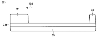
- FIG. 3 is a side view showing the ion generator as viewed from the direction indicated by arrow III in FIG.
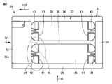
- FIG. 4 is a side view showing the ion generator as viewed from the direction indicated by arrow IV in FIG.
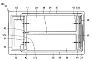
- FIG. 5 is a plan view showing the internal structure of the ion generator in FIG.
- an ion generator 26 in the present embodiment includes an outer case 31, discharge electrodes 41 to 44, an induction electrode (counter electrode) 45, a substrate 51 and a substrate 52, The voltage generation circuit unit 53, the substrate support case 54 and the substrate support case 55, and the wiring 56 and the wiring 57 are included.
- the discharge electrodes 41 to 44 have a needle shape with a sharpened tip.
- the discharge electrodes 41 to 44 are provided in the same plane.
- the discharge electrodes 41 to 44 are arranged so that the central axes of the electrodes are parallel to each other.
- the discharge electrode 41 and the discharge electrode 42 are arranged at a distance in a direction orthogonal to the central axis of the electrode.
- the discharge electrode 43 and the discharge electrode 44 are arranged at a distance in a direction orthogonal to the central axis of the electrode.
- the discharge electrode 41 and the discharge electrode 43 are arranged to face each other with a distance in a direction parallel to the central axis of the electrode.
- the discharge electrode 42 and the discharge electrode 44 are arranged to face each other with a distance in a direction parallel to the central axis of the electrode.
- the central axis of the discharge electrode 41 and the central axis of the discharge electrode 43 are located on the same straight line, and the central axis of the discharge electrode 42 and the central axis of the discharge electrode 44 are located on the same straight line.
- the induction electrode 45 is disposed between the discharge electrode 41 and the discharge electrode 42.
- the induction electrode 45 is provided at a position that is the same distance from the discharge electrode 41 and the discharge electrode 42, and is provided at a position that is the same distance from the discharge electrode 43 and the discharge electrode 44.
- the discharge electrode 41 and the discharge electrode 43 generate ions having different polarities, and the discharge electrode 42 and the discharge electrode 44 generate ions having different polarities.
- the discharge electrode 41 and the discharge electrode 42 generate ions having different polarities, and the discharge electrode 43 and the discharge electrode 44 generate ions having different polarities.
- a positive or negative high voltage is applied to the discharge electrode 41 and a negative or positive high voltage is applied to the discharge electrode 42, a corona discharge is generated between the discharge electrode and the induction electrode 45, and positive ions and Negative ions are generated.
- the discharge electrodes 41 to 44 are not limited to the above arrangement, and for example, the discharge electrode 43 and the discharge electrode 44 may be provided at a position slid from the position in FIG. 5 in a direction perpendicular to the central axis of these electrodes.
- two sets of discharge electrodes arranged opposite to each other are provided (a set of discharge electrode 41 and discharge electrode 43 and a set of discharge electrode 42 and discharge electrode 43). It is good also as a structure which provides one set of discharge electrodes. Even when the central axes of the discharge electrodes 41 to 44 are not parallel to each other, the discharge electrode 41, the discharge electrode 42, the discharge electrode 43, and the discharge electrode 44 sandwich the space 38 described later as a whole. If they are configured to face each other, it can be said that they are arranged to face each other. In the present invention, the number and arrangement of the discharge electrodes are not particularly limited.
- the discharge electrode 41 and the discharge electrode 42 are provided on the substrate 51.
- the discharge electrode 41 and the discharge electrode 42 are provided so as to protrude from one surface 51 a of the substrate 51.
- the high voltage generation circuit unit 53 generates a high voltage to be applied to the discharge electrodes 41 to 44.
- the high voltage generation circuit unit 53 is provided on the other surface 51 b of the substrate 51.
- the substrate support case 54 is provided so as to support the substrate 51 and cover the high voltage generation circuit unit 53.
- the substrate 52 is provided to face the substrate 51.
- the discharge electrode 43 and the discharge electrode 44 are provided on the substrate 52.
- the discharge electrode 43 and the discharge electrode 44 are provided so as to protrude from the surface 52a of the substrate 52 facing the surface 51a.
- the substrate support case 55 is provided to support the substrate 52.
- the wiring 56 and the wiring 57 are provided as connection members that electrically connect the discharge electrode 43 and the discharge electrode 44 to the high voltage generation circuit unit 53, respectively.
- the outer case 31 is provided as a case body that forms the appearance of the ion generator 26.
- the outer case 31 has a shape that can be inserted into the insertion port 23 formed in the duct 22 in FIG. 1.
- the outer case 31 is integrally formed of a resin material.
- the exterior case 31 includes a substrate housing portion 32, a substrate housing portion 33, and rib-shaped portions 34 to 36 as its constituent parts.
- the outer case 31 includes a frame-shaped frame portion 37 including a substrate housing portion 32, a rib-like portion 35, a substrate housing portion 33, and a rib-like portion 34.
- the frame portion 37 has a rectangular frame shape in which four sides are constituted by the substrate accommodation portion 32, the rib-like portion 35, the substrate accommodation portion 33, and the rib-like portion 34.
- the substrate housing part 32 and the substrate housing part 33 are arranged in parallel at a distance from each other.
- the substrate housing part 32 has a larger volume than the substrate housing part 33.
- the rib-like portion 34 and the rib-like portion 35 are arranged in parallel with a distance from each other and orthogonal to the substrate accommodating portion 32 and the substrate accommodating portion 33.
- One ends of the substrate housing portion 32 and the substrate housing portion 33 facing each other are connected by a rib-shaped portion 34.
- the other ends of the substrate housing portion 32 and the substrate housing portion 33 facing each other are connected by a rib-like portion 35.
- the rib-shaped portion 36 is disposed in parallel with the rib-shaped portion 34 and the rib-shaped portion 35.
- the rib-shaped portion 35 connects the substrate housing portion 32 and the substrate housing portion 33 to each other between the rib-shaped portion 34 and the rib-shaped portion 35.
- the rib portions 34 to 36 extend linearly from the substrate housing portion 32 along the central axis direction of the discharge electrode 41 and the discharge electrode 42.
- the rib portions 34 to 36 extend linearly from the substrate housing portion 33 along the central axis direction of the discharge electrode 43 and the discharge electrode 44.
- a space 38 is formed inside the outer case 31 surrounded by the substrate housing portion 32, the rib-like portion 35, the substrate housing portion 33 and the rib-like portion 34. Air flowing through the duct 22 in FIG. 1 is passed through the space 38. The space 38 communicates with the ventilation path formed by the duct 22. The air flowing from the duct 22 to the space 38 is ventilated in the direction orthogonal to the paper surface shown in FIG. The exterior case 31 forms a part of a flow path of air flowing through the duct 22.
- the outer case 31 When the ion generator 26 is attached to the duct 22 in FIG. 1, the outer case 31 is inserted in the direction indicated by the arrow 102 in FIGS. 2 and 3 (hereinafter, the direction indicated by the arrow 102 is referred to as “the outer case 31 Insertion direction ").
- the substrate housing portion 32 is disposed on the back side in the insertion direction of the exterior case 31, and the substrate housing portion 33 is disposed on the near side in the insertion direction of the exterior case 31.
- the rib-shaped portion 34 and the rib-shaped portion 35 extend along the insertion direction of the outer case 31.
- the outer case 31 has a rectangular plan view having a long side extending along the insertion direction of the outer case 31 and a short side extending along a direction orthogonal to the insertion direction of the outer case 31.
- the substrate accommodating portion 32 accommodates a substrate 51, a high voltage generation circuit portion 53, and a substrate support case 54.
- a substrate 52 and a substrate support case 55 are accommodated in the substrate accommodating portion 33.
- the discharge electrode 41 and the discharge electrode 42 extend from the surface 51 a of the substrate 51 to the outside of the outer case 31.
- the discharge electrode 43 and the discharge electrode 44 extend from the surface 52 a of the substrate 52 to the outside of the exterior case 31.
- the tips of the discharge electrodes 41 to 44 extending from the substrates 51 and 52 are disposed in the space 38.
- the tip portions of the discharge electrode 41 and the discharge electrode 43 are disposed in the space 38 between the rib-like portion 34 and the rib-like portion 36, and the tip portions of the discharge electrode 42 and the discharge electrode 44 are rib-like portion 36 and the rib-like portion. It is arranged in a space 38 between the part 35.
- the induction electrode 45 protrudes from the surface 51 a of the substrate 51 toward the inside of the rib-shaped portion 36.
- the leading end portion of the induction electrode 45 is accommodated in the exterior case 31 (rib-shaped portion 36).
- the wiring 56 is routed from the substrate housing portion 32 through the rib-shaped portion 35 toward the substrate housing portion 33.
- the wiring 57 is routed from the substrate housing portion 32 through the rib-shaped portion 34 toward the substrate housing portion 33.
- the wiring 56 is routed so as to pass through one of the rib-like portion 34 and the rib-like portion 35, and the wiring 57 is routed so as to pass either one of the rib-like portion 34 and the rib-like portion 35. Yes.
- the ion generator 26 in the present embodiment further includes a power supply connector 46.
- the power feeding connector 46 is provided in the board housing portion 32 that houses the high voltage generation circuit portion 53.
- the power supply connector 46 is provided as a power supply unit that electrically connects the main body side of the ion generator 100 and the ion generator 26 and supplies power to the high voltage generation circuit unit 53.
- the substrate housing portion 32 has a side surface 32a.
- the side surface 32 a faces the insertion direction of the outer case 31.
- the side surface 32 a is disposed on the leading side of the outer case 31 that is inserted into the duct 22 when the ion generator 26 is mounted.
- the power supply connector 46 is provided on the side surface 32a. With such a configuration, when the ion generator 26 is mounted, the power supply connector 46 is automatically connected to the connector provided on the main body side of the ion generator 100 simultaneously with the operation of inserting the outer case 31 into the duct 22. can do.
- the ion generator 26 in the present embodiment further includes an electrode protection wall 61.
- the electrode protection wall 61 is provided for each of the discharge electrodes 41 to 44.
- the electrode protection wall 61 is provided to protect the discharge electrodes 41 to 44.
- the electrode protection wall 61 is formed integrally with the outer case 31 by a resin material.
- the electrode protection wall 61 may be provided separately from the outer case 31 and may be joined to the outer case 31 by an appropriate joining means.
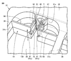
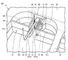
- FIG. 6 is a perspective view showing a range surrounded by a two-dot chain line VI in FIG. 7 is a cross-sectional view showing a range surrounded by a two-dot chain line VI in FIG.
- the structure will be described by paying attention to the electrode protection wall 61 provided for the discharge electrode 42 typically.
- the electrode protection wall 61 has a wall portion 66 and a wall portion 67 as its constituent parts.
- the wall portion 66 and the wall portion 67 are provided in the space 38.
- the wall portion 66 and the wall portion 67 are provided so as to face each other with a space therebetween.
- the wall portion 66 and the wall portion 67 are provided on both sides of the discharge electrode 42.
- the discharge electrode 42 is provided in the space between the wall portion 66 and the wall portion 67.
- the wall portion 66 and the wall portion 67 have a symmetrical shape with the discharge electrode 42 as the center.
- the exterior case 31 has an inner surface 31a, an inner surface 31b, and an inner surface 31c.
- the inner surface 31a, the inner surface 31b, and the inner surface 31c are formed in the substrate housing portion 32, the rib-shaped portion 35, and the rib-shaped portion 36, respectively.
- the inner surface 31 a, the inner surface 31 b, and the inner surface 31 c define a space 38 between the rib-shaped portion 35 and the rib-shaped portion 36.
- the wall portion 66 and the wall portion 67 protrude from the outer case 31 toward the space 38 on both sides of the discharge electrode 42.
- the wall portion 66 and the wall portion 67 protrude from the inner surface 31a of the exterior case 31 (substrate housing portion 32).
- the wall portion 66 and the wall portion 67 are provided so as to protrude from the outer case 31 to be larger than the tip end portion of the discharge electrode 42. That is, the protruding length H1 of the wall portion 66 and the wall portion 67 when the inner surface 31a is a reference is larger than the extension length H2 of the discharge electrode 42 when the inner surface 31a is a reference (H1> H2).
- the wall portion 66 and the wall portion 67 are provided so as to extend in parallel with the ventilation direction in the space 38 (the direction indicated by the arrow 103 in FIG. 6).
- An insulating resin layer 81 is provided on the surface 51 a of the substrate 51.
- the resin layer 81 is provided so as to cover the root portion of the discharge electrode 42 protruding from the surface 51 a of the substrate 51.
- the resin layer 81 is provided on the entire surface 51 a of the substrate 51.
- the opening case 71 is formed in the exterior case 31.
- the opening 71 is formed in the substrate housing part 32.
- the opening 71 is formed so as to penetrate from the inner surface 31 a to the inside of the substrate housing portion 32.
- the opening 71 is formed to expose the substrate 51 around the discharge electrode 42.
- the opening 71 is formed immediately above the surface 51 a of the substrate 51.
- the opening 71 is formed between the wall 66 and the wall 67.
- the discharge electrode 42 is provided so as to extend from the surface 51 a of the substrate 51 to the outside of the exterior case 31 through the opening 71.
- the discharge electrode 42 is provided so as to penetrate the center of the opening 71.
- the opening 71 has a circular opening shape.
- the opening 71 has a size of 9 mm or more in diameter.
- the opening 71 is not limited to a circular shape, and may have an opening shape such as an ellipse, a track shape, or a rectangle.
- the rib-like portion 35 is provided on the opposite side of the opening 71 with respect to the wall 66, and the rib-like portion 36 is opposite to the opening 71 with respect to the wall 67. On the side.
- the wall portion 66 and the wall portion 67 are provided such that the distance between the wall portion 66 and the wall portion 67 is larger on the base portion side than on the tip portion side protruding from the exterior case 31 (L1> L2). ).
- the wall portion 66 and the wall portion 67 have an interval L2 at a position relatively far from the inner surface 31a of the outer case 31, and have an interval L1 larger than L2 at a position relatively closer to the inner surface 31a of the outer case 31. .
- the wall portion 66 and the wall portion 67 have an interval L2 on both sides of the distal end portion of the discharge electrode 42, and have an interval L1 larger than L2 immediately above the opening 71.
- the ion generator 26 is removed from the duct 22 for regular maintenance and replacement.
- the wall 66 and the wall 67 provided on both sides of the discharge electrode 42 prevent the user from touching the sharpened tip of the discharge electrode 42.
- the interval between the wall portion 66 and the wall portion 67 is set to such a size that the user's finger is not inserted on both sides of the distal end portion of the discharge electrode 42. If dirt is attached to the tip of the discharge electrode 42, the discharge electrode 42 can be easily cleaned from between the wall 66 and the wall 67 by using a cotton swab or the like.
- the distance between the wall 66 and the wall 67 is set larger at the base portion near the exterior case 31.
- dirt on the root portion of the discharge electrode 42 and the surface 51 a of the substrate 51 can be removed by inserting a cotton swab into the opening 71.
- the surface 51a of the substrate 51 is resin-molded, the surface 51a can be smoothed. Thereby, the surface 51a of the substrate 51 can be easily cleaned.
- the wall portion 66 and the wall portion 67 are provided so as to extend in parallel with the ventilation direction in the space 38. With such a configuration, the spreading of ions is not inhibited by the wall 66 and the wall 67 on the upstream side and the downstream side of the air blowing to the discharge electrode 42. For this reason, it becomes possible to discharge
- the wall part 66 and the wall part 67 have an inclined part 76 and a parallel part 77 as its constituent parts.
- the inclined portion 76 is a portion having a relatively large interval on the base portion side of the wall portion 66 and the wall portion 67
- the parallel portion 77 is a relatively small interval on the distal end side of the wall portion 66 and the wall portion 67. It is a site
- the inclined portion 76 protrudes from the outer case 31 (substrate housing portion 32) and is provided so that the distance between the wall portion 66 and the wall portion 67 gradually decreases as the distance from the outer case 31 increases.
- the parallel part 77 extends in a direction further away from the outer case 31 from the inclined part 76, and is provided so that the distance between the wall part 66 and the wall part 67 is constant.
- the parallel portions 77 are disposed on both sides of the tip portion of the discharge electrode 42.
- the inclined part 76 and the parallel part 77 are bent and connected to an angle (obtuse angle) larger than 90 °.
- a through hole 72 is formed in the wall portion 66, and a through hole 73 is formed in the wall portion 67.
- the through hole 72 and the through hole 73 are provided so as to penetrate the wall portion 66 and the wall portion 67, respectively.
- the through hole 72 and the through hole 73 are provided on both sides of the distal end portion of the discharge electrode 42.
- the wall 66 and the wall 67 on both sides of the tip are the places where dirt due to electrostatic dust collection is most likely to occur.
- the through-hole 72 and the through-hole 73 in a place where such contamination is most likely to occur, abnormal discharge occurs or between the discharge electrode 42 and the wall portion 66 and the wall portion 67. It is possible to prevent the deposits from bridging.
- the electrode protection wall 61 further has a connecting part 68 and a connecting part 69 as its constituent parts.
- the connecting portion 68 is connected to the rib portion 35 from the wall portion 66.
- the connecting portion 69 is connected to the rib portion 36 from the wall portion 67.
- the connecting portion 68 is bent from the distal end portion of the wall portion 66 and extends toward the inner surface 31 b of the rib-like portion 35.
- the connecting portion 69 is bent from the distal end portion of the wall portion 67 and extends toward the inner surface 31 c of the rib-like portion 36.
- the four corners of the outer casing 31 having a frame shape and the connection portions between the rib-shaped portion 36 and the substrate housing portion 32 and the substrate housing portion 33 are reinforced by the electrode protection wall 61.
- the strength of the case 31 can be increased. Thereby, even when the ion generator 26 is repeatedly attached to and detached from the duct 22, the durability of the exterior case 31 can be sufficiently ensured.
- the structure of the electrode protection wall 61 provided for the discharge electrode 42 has been described.
- the electrode protection wall 61 provided for the discharge electrode 41, the discharge electrode 43, and the discharge electrode 44 also has the same structure. Have.
- the user when the ion generator 26 is removed from the duct 22, the user can connect the discharge electrodes 41 to 44.
- the discharge electrodes 41 to 44 can be easily cleaned from the tip portion to the root portion while preventing the tip portion from being touched.
- the present invention is not limited to this, and the air condition of a dehumidifier, a humidifier, an air conditioner, an air cleaner, or the like is adjusted.
- the present invention may be applied to various air conditioners for conditioning.
- Embodiment 2 Compared with the ion generator 26 in Embodiment 1, the ion generator in Embodiment 2 of this invention is fundamentally provided with the same structure. Hereinafter, the description of the overlapping structure will not be repeated.
- the wall 66 and the wall 67 shown in FIGS. 6 and 7 are bent in a curved shape at the connection position between the inclined portion 76 and the parallel portion 77. According to such a configuration, occurrence of abnormal discharge in the wall portion 66 and the wall portion 67 can be prevented more reliably.
- FIG. 8 is a perspective view showing an ion generating apparatus according to Embodiment 3 of the present invention. In FIG. 8, a range corresponding to FIG. 6 is shown. Compared with the ion generator 26 in Embodiment 1, the ion generator in the present embodiment basically has the same structure. Hereinafter, the description of a part of the overlapping structure will not be repeated.
- the exterior case 31 has an opening 71 formed therein.
- the opening 71 is formed to expose the substrate 51 around the discharge electrode 42.
- the opening 71 is formed between the wall 66 and the wall 67.
- a through hole 72 is formed in the wall portion 66 of the electrode protection wall 61, and a through hole 73 is formed in the wall portion 67 of the electrode protection wall 61.
- the through hole 72 and the through hole 73 are provided so as to penetrate the wall portion 66 and the wall portion 67, respectively.
- the through hole 72 and the through hole 73 are provided on both sides of the distal end portion of the discharge electrode 42.
- the wall portion 66 and the wall portion 67 are provided such that the distance between the wall portion 66 and the wall portion 67 is larger on the base portion side than on the tip portion side protruding from the exterior case 31.
- the wall portion 66 and the wall portion 67 are not limited to such a structure, and the distance between the wall portion 66 and the wall portion 67 is constant from the root portion to the tip portion of the wall portions 66 and 67. It may be provided.
- the electrode protection wall 61 is provided with a notch 91p and a notch 91q (hereinafter referred to as a notch 91 unless otherwise distinguished).
- the notch 91 is provided on the opening 71.
- the notch 91 is provided so as to be projected so as to overlap the opening 71 in the central axis direction of the discharge electrode 42.
- the notch 91 has a notch shape extending in the central axis direction of the discharge electrode 42. When viewed from the central axis direction of the discharge electrode 42, the cutout portion 91 is provided so as to cut out the electrode protection wall 61 in an elliptical shape around the discharge electrode 42.
- the shape of the notch 91 is not limited to the above shape, and for example, the electrode protection wall 61 may be provided so as to be cut out in a circle around the discharge electrode 42. In this case, the distance from the discharge electrode 42 to the wall surface of the notch 91 is equal.
- the notch portion 91p is provided so as to cut out the corner portion of the connecting portion 68 and the wall portion 66.
- the notch 91 p extends in the direction of the central axis of the discharge electrode 42 and is connected to the through hole 72.
- the notch portion 91q is provided so as to cut out the connecting portion 69 and the corner portion of the wall portion 67.
- the notch 91q extends in the central axis direction of the discharge electrode 42 and is connected to the through hole 73.
- FIG. 9 is a perspective view showing how the discharge electrode and the substrate are cleaned in the ion generator in FIG.
- an electrode protection wall 61 for protecting the discharge electrode 42 is provided so that the user cannot easily touch the tip of the discharge electrode 42. It is provided close to the tip.
- deposits are deposited on the distal end portion of the discharge electrode 42 serving as a discharge portion with use.
- the deposit is not limited to the tip of the discharge electrode 42 but is also deposited on the substrate 51 that supports the discharge electrode 42, so the surface 51 a of the substrate 51 needs to be cleaned.
- the wall 66 and the wall 67 provided on both sides of the discharge electrode 42 prevent the user from touching the sharpened tip of the discharge electrode 42.
- the through holes 72 and 73 are formed in the walls 66 and 67 on both sides of the tip of the discharge electrode 42, the wall is located at a position separated from the tip of the discharge electrode 42 by a certain distance. 66, 67 are arranged. With such a configuration, it is possible to suppress a decrease in the amount of ions generated due to deposition of deposits in the discharge part.
- dirt on the root portion of the discharge electrode 42 and the surface 51 a of the substrate 51 can be removed while inserting the cotton swab 92 into the opening 71.
- cleaning is performed while rotating the swab 92 around the discharge electrode 42 by using the notch 91 provided in the electrode protection wall 61 as an insertion port of the swab 92.
- the swab 92 reaches the root portion of the discharge electrode 42 and every corner of the surface 51a of the substrate 51, so that cleaning becomes easy.
- the structure of the electrode protection wall 61 provided for the discharge electrode 42 has been described.
- the electrode protection wall 61 provided for the discharge electrode 41, the discharge electrode 43, and the discharge electrode 44 also has the same structure. Have.
- a sufficient amount of ions can be delivered into the room, and the discharge electrodes 41 to
- an ion generator and an ion generator that can easily perform cleaning on the root portion 44 and the surface 51a of the substrate 51 can be realized.
- An ion generator (26) includes an exterior case (31) that accommodates a substrate (51), and extends from the surface (51a) of the substrate (51) to the outside of the exterior case (31).
- the electrode protection wall (61) is provided so as to protrude from the outer case (31) beyond the tip of the discharge electrode (42), and is opposed to the first wall (66) on both sides of the discharge electrode (42) with a gap therebetween. ) And a second wall (67).
- the exterior case (31) has an opening (71) that is disposed between the first wall (66) and the second wall (67) and exposes the substrate (51).
- the distance between the first wall portion (66) and the second wall portion (67) is at the root of the first wall portion (66) protruding from the outer case (31) and the distal end side of the second wall portion (67).
- the part side is larger.
- the first wall portion and the second wall portion are provided so as to protrude from the outer end portion of the discharge electrode from the front end portion of the discharge electrode and to face each other with a gap therebetween.
- the opening portion can be formed larger in the outer case. It becomes possible. Thereby, the discharge electrode can be easily cleaned through the gap and the opening between the first wall portion and the second wall portion.
- first wall portion (66) and the second wall portion (67) are formed with through holes (72, 73) located on both sides of the distal end portion of the discharge electrode (42).
- the ion generator configured in this way, it is possible to prevent dirt from adhering to the first wall portion and the second wall portion on both sides of the tip portion of the discharge electrode.
- an insulating resin layer (81) is provided on the surface (51a) of the substrate (51) so as to cover the root of the discharge electrode (42).
- the surface of the substrate can be easily cleaned through the opening.
- the exterior case (31) includes a substrate housing portion (32) for housing the substrate (51) and a substrate housing portion (32) on the opposite side of the opening (71) with respect to the first wall portion (66).
- a substrate housing portion (32) for housing the substrate (51) and a substrate housing portion (32) on the opposite side of the opening (71) with respect to the first wall portion (66).
- the electrode protection wall (61) includes a first connecting portion (68) connected from the first wall portion (66) to the first rib-shaped portion (35), and a second rib-shaped portion from the second wall portion (67).
- a second connecting portion (69) connected to (36).
- the strength of the outer case having a frame shape can be improved.
- the exterior case (31) has a frame shape, and forms a space (38) through which ions are released and air is ventilated by the discharge electrode (42).
- the first wall portion (66) and the second wall portion (67) extend parallel to the ventilation direction in the space (38).
- ions emitted from the discharge electrode can be efficiently delivered from the space inside the outer case.
- first wall portion (66) and the second wall portion (67) extend in parallel to each other on both sides of the distal end portion of the discharge electrode (42).
- ions can be more efficiently delivered by stabilizing the air flow around the tip of the discharge electrode.
- the first wall portion (66) and the second wall portion (67) protrude from the outer case (31) and move away from the outer case (31) as the first wall portion (66) and the second wall portion ( 67) and the first wall portion (66) and the second wall portion (67) extending from the inclined portion (76) in a direction away from the outer case (31). And a parallel portion (77) having a constant interval.
- the ion generator configured as described above, it is possible to prevent the occurrence of abnormal discharge by preventing the formation of sharp edge portions on the first wall portion and the second wall portion.
- An ion generator includes an outer case (31) that accommodates a substrate (51), and extends from the surface (51a) of the substrate (51) to the outside of the outer case (31), and discharges.
- the electrode protection wall (61) is provided so as to protrude from the outer case (31) beyond the tip of the discharge electrode (42), and is opposed to the first wall (66) on both sides of the discharge electrode (42) with a gap therebetween.
- the exterior case (31) has an opening (71) that is disposed between the first wall (66) and the second wall (67) and exposes the substrate (51).
- the first wall portion (66) and the second wall portion (67) are formed with through holes (72, 73) located on both sides of the distal end portion of the discharge electrode (42).
- the first wall portion and the second wall portion are provided so as to protrude from the outer end portion of the discharge electrode from the front end portion of the discharge electrode and to face each other with a gap therebetween.
- the through holes are formed in the first wall portion and the second wall portion, it is possible to prevent the dirt from adhering to the first wall portion and the second wall portion on both sides of the distal end portion of the discharge electrode. Further, the discharge electrode and the substrate can be easily cleaned through the gap and the opening between the first wall portion and the second wall portion.
- the electrode protection wall (61) is formed with a notch (91) disposed on the opening (71) and extending along the direction of the central axis of the discharge electrode (42).
- the discharge electrode and the substrate can be more easily cleaned.
- An air conditioner (100) includes a duct (22) that forms a ventilation path, and an ion generator (26) that is detachably attached to the duct (22). ).
- the discharge electrode can be easily cleaned while preventing the user from touching the tip of the discharge electrode, particularly when the ion generator is removed from the duct. .
- This invention is mainly applied to an ion generator mounted on an ion generator, a dehumidifier, a humidifier, an air conditioner, an air cleaner, or the like.
Landscapes
- Health & Medical Sciences (AREA)
- Engineering & Computer Science (AREA)
- Epidemiology (AREA)
- Mechanical Engineering (AREA)
- General Engineering & Computer Science (AREA)
- Combustion & Propulsion (AREA)
- Chemical & Material Sciences (AREA)
- Life Sciences & Earth Sciences (AREA)
- Animal Behavior & Ethology (AREA)
- General Health & Medical Sciences (AREA)
- Public Health (AREA)
- Veterinary Medicine (AREA)
- Disinfection, Sterilisation Or Deodorisation Of Air (AREA)
- Air Filters, Heat-Exchange Apparatuses, And Housings Of Air-Conditioning Units (AREA)
Abstract
Description
図1は、この発明の実施の形態1におけるイオン発生機の内部構造を示す側面図である。図1を参照して、本実施の形態におけるイオン発生機100は、プラスイオンH+(H2O)n(nは0を含む任意の整数)およびマイナスイオンO2 -(H2O)m(mは0を含む任意の整数)を室内に送出し、これらのイオンにより空気中のウイルスを不活性化もしくは死滅させる機能を有する。
この発明の実施の形態2におけるイオン発生装置は、実施の形態1におけるイオン発生装置26と比較して、基本的には同様の構造を備える。以下、重複する構造についてはその説明を繰り返さない。
図8は、この発明の実施の形態3におけるイオン発生装置を示す斜視図である。図8中には、図6に対応する範囲が示されている。本実施の形態におけるイオン発生装置は、実施の形態1におけるイオン発生装置26と比較して、基本的には同様の構造を備える。以下、重複する構造の一部についてはその説明を繰り返さない。
Claims (10)
- 基板を収容する外装ケースと、
前記基板の表面から前記外装ケースの外部に延出し、放電によりイオンを発生させる針状の放電電極と、
前記外装ケースの外部で前記放電電極を保護するための電極保護壁とを備え、
前記電極保護壁は、前記外装ケースから前記放電電極の先端部よりも突出して設けられ、前記放電電極の両側で互いに間隔を設けて対向する第1壁部および第2壁部を有し、
前記外装ケースには、前記第1壁部と前記第2壁部との間に配置され、前記基板を露出させる開口部が形成され、
前記第1壁部と前記第2壁部との間隔は、前記外装ケースから突出する前記第1壁部および前記第2壁部の先端部側よりも根元部側の方が大きい、イオン発生装置。 - 前記第1壁部および前記第2壁部には、前記放電電極の先端部の両側に位置する貫通孔が形成される、請求項1に記載のイオン発生装置。
- 前記基板の表面上には、前記放電電極の根元部を覆うように絶縁性の樹脂層が設けられている、請求項1または2に記載のイオン発生装置。
- 前記外装ケースは、前記基板を収容する基板収容部と、前記第1壁部に対して前記開口部の反対側において前記基板収容部から前記放電電極の延出方向に沿って延びる第1リブ状部と、前記第2壁部に対して前記開口部の反対側において前記基板収容部から前記放電電極の延出方向に沿って延びる第2リブ状部とをさらに有する枠形状を有し、
前記電極保護壁は、前記第1壁部から前記第1リブ状部に連接される第1連接部と、前記第2壁部から前記第2リブ状部に連接される第2連接部とをさらに有する、請求項1から3のいずれか1項に記載のイオン発生装置。 - 前記外装ケースは、枠形状を有し、その内側に前記放電電極によりイオンが放出されるとともに空気が通風される空間を形成し、
前記第1壁部および前記第2壁部は、前記空間における通風方向と平行に延在する、請求項1から4のいずれか1項に記載のイオン発生装置。 - 前記第1壁部および前記第2壁部は、前記放電電極の先端部の両側で互いに平行に延在する、請求項5に記載のイオン発生装置。
- 前記第1壁部および前記第2壁部は、前記外装ケースから突出し、前記外装ケースから離れるに従って前記第1壁部と前記第2壁部との間隔が徐々に小さくなる傾斜部と、前記傾斜部から前記外装ケースより離れる方向に延伸し、前記第1壁部と前記第2壁部との間隔が一定となる平行部とを含む、請求項1から6のいずれか1項に記載のイオン発生装置。
- 基板を収容する外装ケースと、
前記基板の表面から前記外装ケースの外部に延出し、放電によりイオンを発生させる針状の放電電極と、
前記外装ケースの外部で前記放電電極を保護するための電極保護壁とを備え、
前記電極保護壁は、前記外装ケースから前記放電電極の先端部よりも突出して設けられ、前記放電電極の両側で互いに間隔を設けて対向する第1壁部および第2壁部を有し、
前記外装ケースには、前記第1壁部と前記第2壁部との間に配置され、前記基板を露出させる開口部が形成され、
前記第1壁部および前記第2壁部には、前記放電電極の先端部の両側に位置する貫通孔が形成される、イオン発生装置。 - 前記電極保護壁には、前記開口部上に配置され、前記放電電極の中心軸方向に沿って延びる切り欠き部が形成される、請求項8に記載のイオン発生装置。
- 通風路を形成するダクトと、
前記ダクトに対して着脱可能に設けられた、請求項1から9のいずれか1項に記載のイオン発生装置とを備える、空気調和機。
Priority Applications (2)
| Application Number | Priority Date | Filing Date | Title |
|---|---|---|---|
| JP2015532788A JP6050502B2 (ja) | 2013-08-20 | 2014-07-30 | イオン発生装置および空気調和機 |
| CN201480045354.6A CN105474485B (zh) | 2013-08-20 | 2014-07-30 | 离子发生装置和空气调节机 |
Applications Claiming Priority (4)
| Application Number | Priority Date | Filing Date | Title |
|---|---|---|---|
| JP2013-170356 | 2013-08-20 | ||
| JP2013170356 | 2013-08-20 | ||
| JP2014029486 | 2014-02-19 | ||
| JP2014-029486 | 2014-02-19 |
Publications (1)
| Publication Number | Publication Date |
|---|---|
| WO2015025685A1 true WO2015025685A1 (ja) | 2015-02-26 |
Family
ID=52483466
Family Applications (1)
| Application Number | Title | Priority Date | Filing Date |
|---|---|---|---|
| PCT/JP2014/070043 Ceased WO2015025685A1 (ja) | 2013-08-20 | 2014-07-30 | イオン発生装置および空気調和機 |
Country Status (3)
| Country | Link |
|---|---|
| JP (1) | JP6050502B2 (ja) |
| CN (2) | CN105474485B (ja) |
| WO (1) | WO2015025685A1 (ja) |
Families Citing this family (4)
| Publication number | Priority date | Publication date | Assignee | Title |
|---|---|---|---|---|
| US11576996B2 (en) * | 2017-04-10 | 2023-02-14 | Sharp Kabushiki Kaisha | Discharge device and electric machine for improving efficiency of reactive species |
| JP7029466B2 (ja) * | 2017-10-20 | 2022-03-03 | シャープ株式会社 | 放電装置 |
| CN111213296B (zh) * | 2017-10-20 | 2021-07-27 | 夏普株式会社 | 放电装置 |
| JPWO2021230240A1 (ja) * | 2020-05-13 | 2021-11-18 |
Citations (5)
| Publication number | Priority date | Publication date | Assignee | Title |
|---|---|---|---|---|
| JPH09232068A (ja) * | 1996-02-22 | 1997-09-05 | Sunrise Syst:Kk | 負イオン発生装置 |
| JPH10125445A (ja) * | 1996-10-18 | 1998-05-15 | Huegle Electron Kk | イオン発生装置用放電針ユニット |
| JP2011014320A (ja) * | 2009-06-30 | 2011-01-20 | Panasonic Electric Works Sunx Co Ltd | 除電装置 |
| JP2013065537A (ja) * | 2011-05-18 | 2013-04-11 | Sharp Corp | イオン発生装置およびそれを用いた電気機器 |
| JP2013077378A (ja) * | 2011-09-29 | 2013-04-25 | Panasonic Industrial Devices Sunx Co Ltd | 除電装置 |
Family Cites Families (2)
| Publication number | Priority date | Publication date | Assignee | Title |
|---|---|---|---|---|
| TWI362682B (en) * | 2003-12-02 | 2012-04-21 | Keyence Co Ltd | Ionizer and discharge electrode assembly mounted therein |
| JP4720413B2 (ja) * | 2005-03-07 | 2011-07-13 | パナソニック株式会社 | 空気調和機 |
-
2014
- 2014-07-30 CN CN201480045354.6A patent/CN105474485B/zh active Active
- 2014-07-30 CN CN201610961248.3A patent/CN106410614B/zh active Active
- 2014-07-30 WO PCT/JP2014/070043 patent/WO2015025685A1/ja not_active Ceased
- 2014-07-30 JP JP2015532788A patent/JP6050502B2/ja active Active
Patent Citations (5)
| Publication number | Priority date | Publication date | Assignee | Title |
|---|---|---|---|---|
| JPH09232068A (ja) * | 1996-02-22 | 1997-09-05 | Sunrise Syst:Kk | 負イオン発生装置 |
| JPH10125445A (ja) * | 1996-10-18 | 1998-05-15 | Huegle Electron Kk | イオン発生装置用放電針ユニット |
| JP2011014320A (ja) * | 2009-06-30 | 2011-01-20 | Panasonic Electric Works Sunx Co Ltd | 除電装置 |
| JP2013065537A (ja) * | 2011-05-18 | 2013-04-11 | Sharp Corp | イオン発生装置およびそれを用いた電気機器 |
| JP2013077378A (ja) * | 2011-09-29 | 2013-04-25 | Panasonic Industrial Devices Sunx Co Ltd | 除電装置 |
Also Published As
| Publication number | Publication date |
|---|---|
| CN106410614A (zh) | 2017-02-15 |
| CN105474485A (zh) | 2016-04-06 |
| JP6050502B2 (ja) | 2016-12-21 |
| CN105474485B (zh) | 2017-08-25 |
| JPWO2015025685A1 (ja) | 2017-03-02 |
| CN106410614B (zh) | 2018-01-09 |
Similar Documents
| Publication | Publication Date | Title |
|---|---|---|
| CN105308810B (zh) | 离子发生装置和使用其的电气设备 | |
| CN202283365U (zh) | 空气调节机和离子产生单元 | |
| JP6050502B2 (ja) | イオン発生装置および空気調和機 | |
| CN110506373B (zh) | 放电装置以及电气设备 | |
| CN111033131B (zh) | 送风装置 | |
| CN111318374A (zh) | 碳纤维起电装置及具有碳纤维起电装置的电器 | |
| WO2014045991A1 (ja) | 加湿器 | |
| JP2014024017A (ja) | 空気処理装置 | |
| JP6562833B2 (ja) | イオン発生装置および空気調和機 | |
| JP5809009B2 (ja) | イオン発生機能付き送風装置 | |
| JP4323019B2 (ja) | 空気調和機の室内ユニット | |
| JP6681790B2 (ja) | イオン発生装置および電気機器 | |
| WO2015025541A1 (ja) | 空気調和機およびイオン発生装置 | |
| JP5452757B2 (ja) | 送風装置 | |
| JP5293774B2 (ja) | 空気調和機 | |
| JP2016091714A (ja) | イオン発生装置 | |
| JP4528851B2 (ja) | イオン発生装置 | |
| JP2003074888A (ja) | 空気調和機の室内ユニット | |
| CN105492836A (zh) | 空气调节机 | |
| JP2013007552A (ja) | 空気調和機 | |
| JP2019171232A (ja) | 集塵装置及び換気システム | |
| JP6336186B2 (ja) | 放電装置およびそれを用いた電気機器 | |
| CN106537050B (zh) | 空气改质设备 | |
| JP2006035187A (ja) | 電気集塵装置 | |
| JP2011258469A (ja) | イオン発生装置、空気清浄機、イオン発生方法 |
Legal Events
| Date | Code | Title | Description |
|---|---|---|---|
| WWE | Wipo information: entry into national phase |
Ref document number: 201480045354.6 Country of ref document: CN |
|
| 121 | Ep: the epo has been informed by wipo that ep was designated in this application |
Ref document number: 14837227 Country of ref document: EP Kind code of ref document: A1 |
|
| ENP | Entry into the national phase |
Ref document number: 2015532788 Country of ref document: JP Kind code of ref document: A |
|
| NENP | Non-entry into the national phase |
Ref country code: DE |
|
| 122 | Ep: pct application non-entry in european phase |
Ref document number: 14837227 Country of ref document: EP Kind code of ref document: A1 |