WO2015019783A1 - フライホイール回生システム及びその制御方法 - Google Patents
フライホイール回生システム及びその制御方法 Download PDFInfo
- Publication number
- WO2015019783A1 WO2015019783A1 PCT/JP2014/068352 JP2014068352W WO2015019783A1 WO 2015019783 A1 WO2015019783 A1 WO 2015019783A1 JP 2014068352 W JP2014068352 W JP 2014068352W WO 2015019783 A1 WO2015019783 A1 WO 2015019783A1
- Authority
- WO
- WIPO (PCT)
- Prior art keywords
- flywheel
- regeneration
- deceleration
- clutch
- flywheel regeneration
- Prior art date
- Legal status (The legal status is an assumption and is not a legal conclusion. Google has not performed a legal analysis and makes no representation as to the accuracy of the status listed.)
- Ceased
Links
Images

Classifications
-
- B—PERFORMING OPERATIONS; TRANSPORTING
- B60—VEHICLES IN GENERAL
- B60K—ARRANGEMENT OR MOUNTING OF PROPULSION UNITS OR OF TRANSMISSIONS IN VEHICLES; ARRANGEMENT OR MOUNTING OF PLURAL DIVERSE PRIME-MOVERS IN VEHICLES; AUXILIARY DRIVES FOR VEHICLES; INSTRUMENTATION OR DASHBOARDS FOR VEHICLES; ARRANGEMENTS IN CONNECTION WITH COOLING, AIR INTAKE, GAS EXHAUST OR FUEL SUPPLY OF PROPULSION UNITS IN VEHICLES
- B60K6/00—Arrangement or mounting of plural diverse prime-movers for mutual or common propulsion, e.g. hybrid propulsion systems comprising electric motors and internal combustion engines
- B60K6/08—Prime-movers comprising combustion engines and mechanical or fluid energy storing means
- B60K6/10—Prime-movers comprising combustion engines and mechanical or fluid energy storing means by means of a chargeable mechanical accumulator, e.g. flywheel
-
- Y—GENERAL TAGGING OF NEW TECHNOLOGICAL DEVELOPMENTS; GENERAL TAGGING OF CROSS-SECTIONAL TECHNOLOGIES SPANNING OVER SEVERAL SECTIONS OF THE IPC; TECHNICAL SUBJECTS COVERED BY FORMER USPC CROSS-REFERENCE ART COLLECTIONS [XRACs] AND DIGESTS
- Y02—TECHNOLOGIES OR APPLICATIONS FOR MITIGATION OR ADAPTATION AGAINST CLIMATE CHANGE
- Y02T—CLIMATE CHANGE MITIGATION TECHNOLOGIES RELATED TO TRANSPORTATION
- Y02T10/00—Road transport of goods or passengers
- Y02T10/60—Other road transportation technologies with climate change mitigation effect
- Y02T10/62—Hybrid vehicles
Definitions
- the present invention relates to flywheel regeneration technology for regenerating kinetic energy of a vehicle with a flywheel.
- JP2012-516417A is provided with a flywheel that can be engaged and disengaged by a clutch (hereinafter referred to as a flywheel clutch) on an input shaft of a transmission, and when the vehicle decelerates, the flywheel clutch is engaged and rotation is input from a drive wheel.
- a flywheel clutch a clutch that can be engaged and disengaged by a clutch (hereinafter referred to as a flywheel clutch) on an input shaft of a transmission, and when the vehicle decelerates, the flywheel clutch is engaged and rotation is input from a drive wheel.
- flywheel regeneration system if the flywheel clutch is released, the regenerated kinetic energy can be stored in the flywheel, and if the flywheel clutch is engaged during start-up or acceleration, it is stored in the flywheel.
- the released kinetic energy can be released and used for starting and accelerating the vehicle.
- the present invention has been made in view of such technical problems, and it is an object of the present invention to prevent the sudden engagement or the engagement delay of the flywheel clutch or both by appropriately permitting or prohibiting the flywheel regeneration.
- the flywheel, the flywheel clutch, the power source clutch, and the flywheel clutch are connected to the flywheel and the power source clutch is connected to the power source.
- a flywheel regeneration system comprising: a rotary shaft that transmits rotation to a drive wheel; and a flywheel regeneration system that regenerates kinetic energy of the vehicle by engaging the flywheel clutch during vehicle deceleration.
- Regenerative permission means for determining whether to permit regeneration based on the requested deceleration; and regenerative execution means for engaging the flywheel clutch and performing the flywheel regeneration when the flywheel regeneration is permitted.
- a provided flywheel regeneration system is provided.
- a method for controlling the flywheel regeneration system is provided.
- flywheel regeneration is determined based on the requested deceleration, flywheel regeneration is not performed during rapid deceleration or slow deceleration or both. Can be properly permitted or prohibited.
- FIG. 1 is an overall configuration diagram of a vehicle including a flywheel regeneration system.
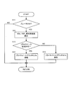
- FIG. 2 is a flowchart showing the contents of the regeneration control.
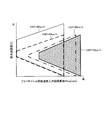
- FIG. 3 is a map for determining success or failure of the regeneration permission condition.
- FIG. 1 shows an overall configuration of a vehicle 100 provided with a flywheel regeneration system according to an embodiment of the present invention.
- the vehicle 100 decelerates the output rotation of the engine 1 as a power source, a flywheel 2 for regeneration, a continuously variable transmission (hereinafter referred to as CVT) 3 that continuously changes the output rotation of the engine 1, and the CVT 3.
- CVT continuously variable transmission
- a final reduction gear 4, a differential 5, left and right drive wheels 6, a hydraulic circuit 7, and a controller 8 are provided.
- the engine clutch CL1 is provided between the engine 1 and the input shaft 3in of the CVT 3.
- the engine clutch CL1 is a hydraulic clutch capable of controlling the fastening torque capacity with supplied hydraulic pressure.
- the forward clutch CL2 is a hydraulic clutch whose fastening torque capacity can be controlled by supplied hydraulic pressure.
- the forward clutch CL2 is provided alone in FIG. 1, but more specifically, a clutch (including a brake) that realizes a forward state in a stepped transmission or a forward / reverse switching mechanism provided between the CVT 3 and the final reduction gear 4. )one of.
- the oil pump 10 is connected to the input shaft 3in of the CVT 3 via a belt, gear, etc. (not shown).
- the oil pump 10 is a gear pump type or vane pump type oil pump that generates hydraulic pressure when the input shaft 3in of the CVT 3 rotates.
- the hydraulic pressure generated by the oil pump 10 is sent to the hydraulic circuit 7 and supplied from the hydraulic circuit 7 to the pulley of the CVT 3, the engine clutch CL1, and the forward clutch CL2.
- the flywheel 2 is further connected to the input shaft 3 in of the CVT 3 via a pair of reduction gear trains 11 and 12.
- the flywheel 2 is a metal cylinder or disk, and is housed in a container that is vacuumed or decompressed to reduce windage loss during rotation.
- a flywheel clutch CLfw is provided between the reduction gear train 11 and the reduction gear train 12.
- the flywheel clutch CLfw is an electric clutch that can be switched between engagement and disengagement by the clutch actuator 13.
- An electric oil pump may be provided instead of the clutch actuator 13, and the flywheel clutch CLfw may be a hydraulic clutch capable of controlling the fastening torque capacity by the hydraulic pressure generated by the electric oil pump.
- the hydraulic circuit 7 is configured by a solenoid valve or the like that operates in response to a signal from a controller 8 described later, and is connected to the CVT 3, the engine clutch CL1, the forward clutch CL2, and the oil pump 10 through an oil passage.
- the hydraulic circuit 7 generates the hydraulic pressure required by the pulley of the CVT 3, the engine clutch CL 1, and the forward clutch CL 2 using the hydraulic pressure generated by the oil pump 10 as the original pressure, and the generated hydraulic pressure is used as the pulley of the CVT 3, the engine clutch CL 1, and Supply to forward clutch CL2.
- the brake 14 is an electronically controlled brake in which the brake pedal 15 and the master cylinder 16 are mechanically independent.
- the brake actuator 17 displaces the piston of the master cylinder 16, and the hydraulic pressure corresponding to the required deceleration (deceleration of the vehicle 100 requested by the driver, the same applies hereinafter) is supplied to the brake 14. Braking force is generated.
- the brake 14 is also provided on the driven wheel.
- the controller 8 includes a CPU, a RAM, an input / output interface, and the like.
- the controller 8 includes a rotation speed sensor 21 that detects the rotation speed of the engine 1, and a rotation speed sensor 22 that detects the rotation speed Nin of the input shaft 3in of the CVT 3. , A rotational speed sensor 23 for detecting the rotational speed Nfw of the flywheel 2, a vehicle speed sensor 24 for detecting the vehicle speed VSP, an accelerator opening sensor 26 for detecting the opening APO of the accelerator pedal 25, and the depression amount of the brake pedal 15 by the driver And the signal from the brake sensor 27 etc. which detects depression acceleration is input.
- the controller 8 performs various calculations based on the input signal, and controls the shift of the CVT 3, the engagement / release of the clutches CL1, CL2, and CLfw, and the brake actuator 17. In particular, when the driver depresses the brake pedal 15 and the vehicle 100 decelerates, the controller 8 fastens the flywheel clutch CLfw, rotates the flywheel 2 by the rotation input from the drive wheels 6, and the vehicle 100 The kinetic energy of the vehicle 100 is regenerated by converting the kinetic energy it has into the kinetic energy of the flywheel 2.
- the controller 8 calculates the required deceleration with reference to a predetermined map based on the depression amount and depression acceleration of the brake pedal 15 detected by the brake sensor 27, the vehicle speed VSP, etc., and responds to the required deceleration.
- the engagement torque capacity of the flywheel clutch CLfw is controlled so that a braking force (regenerative brake) is obtained. For example, when the required deceleration is large, the engagement torque capacity of the flywheel clutch CLfw is increased compared to when the required deceleration is small. That is, the time required for engaging the flywheel clutch CLfw is shortened.
- the controller 8 When the regenerative brake cannot be generated before the flywheel clutch CLfw is engaged, or when the required deceleration cannot be realized only with the regenerative brake, the controller 8 operates the brake actuator 17 to increase the braking force of the brake 14 to reduce the request. Let speed be realized.
- the regenerated kinetic energy can be stored in the flywheel 2 by releasing the flywheel clutch CLfw. If the flywheel clutch CLfw is engaged in a state where kinetic energy is stored in the flywheel 2, the kinetic energy stored in the flywheel 2 can be used for starting and acceleration of the vehicle 100.
- FIG. 2 is a flowchart showing the contents of the regenerative control executed by the controller 8.
- the contents of the regeneration control will be described with reference to this.
- the controller 8 determines whether or not the brake pedal 15 is depressed based on a signal input from the brake sensor 27. If it is determined that the brake pedal 15 is depressed, the process proceeds to S12 to perform flywheel regeneration.
- the controller 8 reads the rotational speed Nfw, the vehicle speed VSP, and the requested deceleration of the flywheel 2.
- the required deceleration is a value calculated with reference to a predetermined map based on the depression amount and depression acceleration of the brake pedal 15, the vehicle speed VSP, and the like.
- a flywheel regeneration permission area (in the figure, a trapezoidal area. Only the flywheel regeneration permission area at a vehicle speed of 70 km / h is hatched) is set for each vehicle speed.
- the flywheel regeneration permission area is set in consideration of the heat generation of the flywheel clutch CLfw when the flywheel clutch CLfw is engaged and the time required to engage the flywheel clutch CLfw.
- the boundary line on the high demand deceleration side of the flywheel regeneration permission area (hereinafter referred to as the upper boundary line) is such that the heat generation rate of the flywheel clutch CLfw reaches the upper limit heat generation rate when the flywheel clutch CLfw is engaged. It is determined by whether or not the differential rotation of the flywheel clutch CLfw is large.
- the flywheel clutch CLfw In the case of rapid deceleration where the required deceleration is larger than the upper limit deceleration determined by the upper boundary line, the flywheel clutch CLfw is engaged in a short time. Therefore, if the flywheel clutch CLfw is engaged and the flywheel regeneration is performed, the flywheel clutch CLfw is engaged. Since the heat generation rate of the wheel clutch CLfw may exceed the upper limit heat generation rate, flywheel regeneration is prohibited.
- the engagement time of the flywheel clutch CLfw is longer than in the case of sudden deceleration, so the flywheel clutch CLfw is engaged and flywheel regeneration is performed. Since the heat generation rate of the flywheel clutch CLfw does not exceed the upper limit heat generation rate, flywheel regeneration is permitted.
- flywheel rotational speed input shaft equivalent value Nfwin is increased to the rotational speed corresponding to the right boundary line.
- flywheel regeneration is performed to increase the rotational speed Nfw of the flywheel 2 even if the flywheel clutch CLfw is engaged. In this case, flywheel regeneration is prohibited.
- the boundary line (lower boundary line) on the low required deceleration side of the flywheel regeneration permission area is the allowable time (for example, 2 seconds) from the start of the engagement of the flywheel clutch CLfw to the completion of the engagement. It is set depending on whether or not it becomes shorter than 3 seconds).
- the lower limit deceleration determined by the lower boundary line decreases as the flywheel rotational speed input shaft equivalent value Nfwin at the start of flywheel regeneration decreases.
- the higher the flywheel rotational speed input shaft equivalent value Nfwin the higher the flywheel clutch CLfw.
- Change amount of the flywheel rotational speed input shaft converted value Nfwin before and after the fastening of ( rotational speed corresponding to the right boundary line-flywheel rotational speed input shaft converted value Nfwin at the start of flywheel regeneration), that is, the flywheel 2
- the time from the start of the engagement of the flywheel clutch CLfw to the completion of the engagement is shortened after the rotation pulling width is reduced, and the engagement of the flywheel clutch CLfw is completed within the allowable time even with a smaller required deceleration. It is because it can be made.
- the lower boundary line moves to the lower required deceleration side as the vehicle speed VSP is lower.
- the flywheel rotational speed input shaft equivalent value Nfwin increases to the rotational speed corresponding to the right boundary line. This is because the lower the vehicle speed VSP, the lower the rotational speed corresponding to the right boundary line, and the shorter the time required to engage the flywheel clutch CLfw.
- the boundary of the flywheel regeneration permission area on the low flywheel rotational speed input conversion value side (hereinafter, the left boundary line) is the difference between the upper limit deceleration determined by the upper boundary line and the lower limit deceleration determined by the lower boundary line. Is set for each vehicle speed corresponding to the flywheel rotational speed input shaft converted value Nfwin smaller than the predetermined lower limit value.
- flywheel regeneration permission area is narrowed, and even if flywheel regeneration is permitted and flywheel regeneration is started, Immediately after that, the flywheel regeneration is prohibited and the flywheel regeneration is prohibited, and the flywheel clutch CLfw is repeatedly engaged / released. In such a case, flywheel regeneration should be prohibited because it may give a sense of incongruity.
- flywheel regeneration it is determined whether flywheel regeneration is permitted. If flywheel regeneration is permitted, the process proceeds to S14, and the controller 8 The clutch CLfw is engaged and flywheel regeneration is started. On the other hand, when the flywheel regeneration is prohibited, the process proceeds to S15, and the controller 8 releases the flywheel clutch CLfw and does not perform the flywheel regeneration.
- the controller 8 determines whether to permit flywheel regeneration based on the requested deceleration, and engages the flywheel clutch CLfw when the vehicle is decelerated and when flywheel regeneration is permitted. And flywheel regeneration.
- flywheel regeneration By determining whether to allow flywheel regeneration based on the required deceleration, flywheel regeneration is properly permitted / prohibited so that flywheel regeneration is not performed during rapid deceleration or slow deceleration or both. It can be carried out.
- flywheel regeneration can be appropriately performed depending on the vehicle speed. Also, depending on the vehicle speed, the amount of heat generated when the flywheel clutch CLfw is engaged and the time required to engage the flywheel clutch CLfw vary, but the required deceleration permitting flywheel regeneration is changed based on the vehicle speed. By doing so, permission / prohibition of flywheel regeneration can be appropriately performed.
- flywheel regeneration is prohibited when the required deceleration is greater than the upper limit deceleration, and flywheel regeneration is permitted when the required deceleration is less than the upper limit deceleration.
- flywheel regeneration is not performed during sudden deceleration, and a decrease in durability due to heat generated by the flywheel clutch can be prevented.
- flywheel regeneration is prohibited when the required deceleration is slower than the lower limit deceleration, and flywheel regeneration is allowed when the required deceleration is greater than the lower limit deceleration.
- flywheel regeneration is not performed during slow deceleration, and the regenerative state can be prevented from continuing longer than necessary.
- flywheel regeneration is prohibited when the flywheel rotation speed input shaft conversion value Nfwin at the start of flywheel regeneration is lower than the lower limit rotation speed at which the difference between the upper limit deceleration and the lower limit deceleration is a predetermined lower limit value. I tried to do it. This prevents repeated engagement / disengagement of the flywheel clutch CLfw when the flywheel regeneration permission area is narrowed, and a decrease in durability of the flywheel clutch CLfw and occurrence of shock due to repeated engagement / release. Can be prevented.
- the vehicle 100 includes only the engine 1 as a power source.
- the vehicle 100 may include the engine 1 and a motor as power sources, or may include only a motor instead of the engine 1. Good.
- the vehicle 100 includes the CVT 3 as a transmission
- the type of the transmission is not limited to this, and may include a stepped transmission instead of the CVT 3.
Landscapes
- Engineering & Computer Science (AREA)
- Chemical & Material Sciences (AREA)
- Combustion & Propulsion (AREA)
- Transportation (AREA)
- Mechanical Engineering (AREA)
- Arrangement Or Mounting Of Propulsion Units For Vehicles (AREA)
- Hybrid Electric Vehicles (AREA)
- Electric Propulsion And Braking For Vehicles (AREA)
Abstract
コントローラは、フライホイール回生を許可するかを要求減速度に基づき判断し、フライホイール回生が許可されている場合に、フライホイールクラッチを締結してフライホイール回生を行う。
Description
本発明は、車両の運動エネルギーをフライホイールで回生するフライホイール回生技術に関する。
車両の燃費・電費を向上させるには、車両が減速する時に車両の運動エネルギーを電気的又は機械的に回生し、回生したエネルギーを発進時や加速時に利用するのが有効である。
JP2012-516417Aは、変速機の入力軸にクラッチ(以下、フライホイールクラッチ)によって断続可能なフライホイールを設け、車両が減速する時にフライホイールクラッチを締結して駆動輪から入力される回転でフライホイールを回転させ、車両の運動エネルギーをフライホイールの運動エネルギーに変換するフライホイール回生システムを開示している。
このようなフライホイール回生システムにおいては、フライホイールクラッチを解放すれば回生した運動エネルギーをフライホイールに保存することができ、また、発進時や加速時にフライホイールクラッチを締結すれば、フライホイールに保存された運動エネルギーを放出させ、車両の発進や加速に利用することができる。
フライホイール回生システムにおいては、回生中、エンジン等の動力源を切り離し、要求減速度(運転者が要求する車両の減速度、以下同じ)に応じた締結トルク容量でフライホイールクラッチを締結すれば、要求減速度に応じた減速を実現することができる。
しかしながら、この構成では、要求減速度が大きい急減速では、要求減速度を満足すべくフライホイールクラッチを急締結させるので、フライホイールクラッチが発熱し、耐久性の低下が問題となる。
逆に、要求減速度が小さい緩減速では、要求減速度を満足すべくフライホイールクラッチを時間をかけて締結させるので、フライホイールクラッチの締結がなかなか完了せず、回生状態が必要以上に長く続くという問題が生じる。
回生中は、動力源がパワートレインから切り離され、かつ、フライホイールクラッチがスリップしており、動力源又はフライホイールでオイルポンプを駆動する構成では、回生中のオイルポンプ回転速度が低く、変速機を変速させるのに必要な油圧を確保できず、再加速要求があっても変速機の変速が遅れる可能性がある。
回生状態が必要以上に長く続くと、回生中に再加速要求が生じる可能性が高くなり、変速遅れによる加速不良が生じる可能性が高くなる。
本発明は、このような技術的課題に鑑みてなされたもので、フライホイール回生の許可・禁止を適切に行うことで、フライホイールクラッチの急締結又は締結遅れ又はその両方を防止することを目的とする。
本発明のある態様によれば、フライホイールと、フライホイールクラッチと、動力源クラッチと、前記フライホイールクラッチを介して前記フライホイールと接続されるとともに前記動力源クラッチを介して動力源と接続され、駆動輪に回転を伝達する回転軸とを備え、車両減速中に前記フライホイールクラッチを締結して前記車両の運動エネルギーを回生するフライホイール回生を行うフライホイール回生システムであって、前記フライホイール回生を許可するかを要求減速度に基づき判断する回生許可手段と、前記フライホイール回生が許可されている場合に、前記フライホイールクラッチを締結して前記フライホイール回生を行う回生実行手段と、を備えたフライホイール回生システムが提供される。
また、本発明の別の態様によれば、上記フライホイール回生システムの制御方法が提供される。
これらの態様によれば、フライホイール回生を許可するかを要求減速度に基づき判断するようにしたことで、急減速又は緩減速又はその両方ではフライホイール回生を行わないというように、フライホイール回生の許可・禁止を適切に行うことができる。
以下、添付図面を参照しながら本発明の実施形態について説明する。
図1は、本発明の実施形態に係るフライホイール回生システムを備えた車両100の全体構成を示している。
車両100は、動力源としてのエンジン1と、回生用のフライホイール2と、エンジン1の出力回転を無段階に変速する無段変速機(以下、CVT)3と、CVT3の出力回転を減速する終減速装置4と、差動装置5と、左右の駆動輪6と、油圧回路7と、コントローラ8とを備えている。
エンジン1とCVT3の入力軸3inとの間には、エンジンクラッチCL1が設けられている。エンジンクラッチCL1は、供給される油圧によって締結トルク容量を制御可能な油圧式クラッチである。
CVT3と終減速装置4との間には、発進・前進時に締結され、CVT3を介して入力されるエンジン1又はフライホイール2からの回転を終減速装置4に伝達する前進クラッチCL2が設けられている。前進クラッチCL2は、供給される油圧によって締結トルク容量を制御可能な油圧式クラッチである。前進クラッチCL2は、図1では単独で設けられているが、詳細には、CVT3と終減速装置4の間に設けられる有段変速機又は前後進切換機構において前進状態を実現するクラッチ(ブレーキ含む)の一つである。
CVT3の入力軸3inには図示しないベルト、ギヤ等を介してオイルポンプ10が接続されている。オイルポンプ10は、CVT3の入力軸3inが回転すると油圧を発生させるギヤポンプ式又はベーンポンプ式のオイルポンプである。オイルポンプ10が発生した油圧は油圧回路7へと送られ、油圧回路7からCVT3のプーリ、エンジンクラッチCL1、前進クラッチCL2に供給される。
CVT3の入力軸3inには、さらに、一対の減速ギヤ列11、12を介してフライホイール2が接続されている。フライホイール2は、金属製の円筒体又は円盤であり、回転時の風損を低減するために真空又は減圧された容器内に収容されている。
減速ギヤ列11と減速ギヤ列12との間にはフライホイールクラッチCLfwが設けられている。フライホイールクラッチCLfwは、クラッチアクチュエータ13によって締結・解放を切り換えることのできる電動クラッチである。クラッチアクチュエータ13に代えて電動オイルポンプを設け、フライホイールクラッチCLfwを、電動オイルポンプで発生した油圧によって締結トルク容量を制御可能な油圧式クラッチとしてもよい。
油圧回路7は、後述するコントローラ8からの信号を受けて動作するソレノイド弁等で構成され、CVT3、エンジンクラッチCL1、前進クラッチCL2及びオイルポンプ10と油路を介して接続される。油圧回路7は、オイルポンプ10で発生した油圧を元圧として、CVT3のプーリ、エンジンクラッチCL1及び前進クラッチCL2で必要とされる油圧を生成し、生成した油圧をCVT3のプーリ、エンジンクラッチCL1及び前進クラッチCL2に供給する。
ブレーキ14は、ブレーキペダル15とマスターシリンダ16とが機構的に独立している電子制御式ブレーキである。運転者がブレーキペダル15を踏み込むと、ブレーキアクチュエータ17がマスターシリンダ16のピストンを変位させ、要求減速度(運転者が要求する車両100の減速度、以下同じ)に応じた油圧がブレーキ14に供給され、制動力が発生する。なお、図示は省略するが、ブレーキ14は従動輪にも設けられている。
コントローラ8は、CPU、RAM、入出力インターフェース等で構成され、コントローラ8には、エンジン1の回転速度を検出する回転速度センサ21、CVT3の入力軸3inの回転速度Ninを検出する回転速度センサ22、フライホイール2の回転速度Nfwを検出する回転速度センサ23、車速VSPを検出する車速センサ24、アクセルペダル25の開度APOを検出するアクセル開度センサ26、運転者によるブレーキペダル15の踏み込み量及び踏み込み加速度を検出するブレーキセンサ27等からの信号が入力される。
コントローラ8は、入力される信号に基づき各種演算を行い、CVT3の変速、クラッチCL1、CL2、CLfwの締結・解放、ブレーキアクチュエータ17を制御する。特に、運転者がブレーキペダル15を踏み込み、車両100が減速する時は、コントローラ8は、フライホイールクラッチCLfwを締結し、駆動輪6から入力される回転でフライホイール2を回転させ、車両100が持つ運動エネルギーをフライホイール2の運動エネルギーに変換することで、車両100の運動エネルギーを回生する。
回生中、コントローラ8は、ブレーキセンサ27で検出されるブレーキペダル15の踏み込み量及び踏み込み加速度、車速VSP等に基づき、所定のマップを参照して要求減速度を演算し、要求減速度に応じた制動力(回生ブレーキ)が得られるようフライホイールクラッチCLfwの締結トルク容量を制御する。例えば、要求減速度が大きい場合は、要求減速度が小さい場合に比べて、フライホイールクラッチCLfwの締結トルク容量を大きくする。すなわち、フライホイールクラッチCLfwの締結に要する時間が短くなる。フライホイールクラッチCLfwを締結する前で回生ブレーキを発生できない場合や回生ブレーキのみでは要求減速度を実現できない場合は、コントローラ8はブレーキアクチュエータ17を動作させてブレーキ14の制動力を増大させて要求減速度が実現されるようにする。
回生された運動エネルギーは、フライホイールクラッチCLfwを解放することによってフライホイール2に保存することができる。そして、フライホイール2に運動エネルギーが保存されている状態でフライホイールクラッチCLfwを締結すれば、フライホイール2に保存されている運動エネルギーを車両100の発進や加速に利用することができる。
図2は、コントローラ8が実行する回生制御の内容を示したフローチャートである。以下、これを参照しながら回生制御の内容について説明する。
これによると、まず、S11では、コントローラ8は、ブレーキセンサ27から入力される信号に基づき、ブレーキペダル15が踏み込まれているか判断する。ブレーキペダル15が踏み込まれていると判断された場合は、フライホイール回生を行うべく、処理がS12に進む。
S12では、コントローラ8は、フライホイール2の回転速度Nfw、車速VSP、要求減速度を読み込む。要求減速度は、上記の通り、ブレーキペダル15の踏み込み量及び踏み込み加速度、車速VSP等に基づき、所定のマップを参照して演算される値である。
S13では、コントローラ8は、フライホイール2の回転速度Nfwの入力軸換算値(=Nfw÷減速ギヤ列11、12の減速比、以下、フライホイール回転速度入力軸換算値)Nfwin、車速VSP、要求減速度に基づき、図3に示すマップを参照してフライホイール回生が許可されているか判断する。
図3に示すマップにおいては、車速毎にフライホイール回生許可領域(図中、台形領域。車速70km/h時のフライホイール回生許可領域のみハッチングが付されている)が設定されており、各車速のフライホイール回生許可領域は、フライホイールクラッチCLfw締結時のフライホイールクラッチCLfwの発熱、フライホイールクラッチCLfwの締結に要する時間を考慮して設定されている。
具体的には、フライホイール回生許可領域の高要求減速度側の境界線(以下、上側境界線)は、フライホイールクラッチCLfwを締結した時にフライホイールクラッチCLfwの発熱率が上限発熱率に達するほどフライホイールクラッチCLfwの差回転が大きいか否かにより決定されている。上限発熱率は、フライホイールクラッチCLfwの耐久性が低下する発熱率よりも若干低めの値(=耐久性が低下する発熱率-余裕代)に設定される値である。
フライホイール回生開始時のフライホイール回転速度入力軸換算値Nfwinが高いほど上限境界線で決まる上限減速度が大きくなるのは、フライホイール回生開始時のフライホイール回転速度入力軸換算値Nfwinが高いほどフライホイールクラッチCLfwを締結するときの差回転が小さくなり、フライホイールクラッチCLfwの発熱が抑えられるので、より大きな要求減速度に対しても対応することができるからである。
上側境界線で決まる上限減速度よりも要求減速度が大きい急減速の場合は、短時間でフライホイールクラッチCLfwの締結が行われるので、フライホイールクラッチCLfwを締結してフライホイール回生を行うとフライホイールクラッチCLfwの発熱率が上限発熱率を超える可能性があるので、フライホイール回生が禁止される。
これに対し、上限減速度よりも要求減速度が小さい場合は、急減速の場合に比べてフライホイールクラッチCLfwの締結時間が長くなるので、フライホイールクラッチCLfwを締結してフライホイール回生を行ってもフライホイールクラッチCLfwの発熱率が上限発熱率を超えることがないので、フライホイール回生が許可される。
急減速ほどフライホイールクラッチCLfwに蓄積される発熱量のピーク値が高くなるので、フライホイールクラッチCLfwの耐久性の低下を招く。したがって、上述したように、要求減速度が上側境界線で決まる上限減速度よりも大きいか否かにより、フライホイール回生の許可、禁止を判断している。
車速VSPが高いほど上側境界線が低要求減速度側に移動するのは、車速VSPが高いほどフライホイールクラッチCLfwの差回転が大きくなり、フライホイール回生開始時のフライホイール回転速度入力軸換算値Nfwinが同じであっても許容できる要求減速度が小さくなることに対応させたためである。
また、フライホイール回生許可領域の高フライホイール回転速度入力換算値側の境界線(以下、右側境界線)は、コースト車速に対応するCVT3の入力軸の回転速度、及び、必要油圧収支(=CVT3の変速に必要な油圧+駆動輪6からの入力に対してCVT3のベルトをスリップさせないために必要な油圧)から決まるCVT3の入力軸の最低回転速度のうち高い方によって決定される。
フライホイールクラッチCLfwを締結すると、フライホイール回転速度入力軸換算値Nfwinが右側境界線に対応する回転速度まで高められる。言い換えれば、フライホイール回転速度入力軸換算値Nfwinが右側境界線に対応する回転速度よりも高ければ、フライホイールクラッチCLfwを締結してもフライホイール2の回転速度Nfwを上昇させるフライホイール回生を行うことができないので、この場合はフライホイール回生が禁止される。
30km/hの場合と40km/hの場合とで右側境界線が一致しているのは、これらの車速では、コースト車速よりも必要油圧収支から決まるCVT3の入力軸の最低回転速度(=固定値、例えば、1200rpm)の方が高くなり、後者に合わせて右側境界線が設定されるからである。
また、フライホイール回生許可領域の低要求減速度側の境界線(下側境界線)は、フライホイールクラッチCLfwの締結を開始してから締結が完了するまでの時間が許容時間(例えば、2秒~3秒)よりも短くなるか否かによって設定されている。
フライホイール回生開始時のフライホイール回転速度入力軸換算値Nfwinが高いほど下側境界線で決まる下限減速度が小さくなるのは、フライホイール回転速度入力軸換算値Nfwinが高いほど、フライホイールクラッチCLfwの締結前後のフライホイール回転速度入力軸換算値Nfwinの変化量(=右側境界線に対応する回転速度-フライホイール回生開始時のフライホイール回転速度入力軸換算値Nfwin)、すなわち、フライホイール2の回転引き上げ幅が小さくなってフライホイールクラッチCLfwの締結を開始してから締結が完了するまでの時間が短くなり、より小さな要求減速度であっても許容時間内でフライホイールクラッチCLfwの締結を完了させることができるからである。
下側境界線で決まる下限減速度よりも要求減速度が小さい緩減速の場合は、フライホイールクラッチCLfwの締結を開始してから締結が完了するまでの時間が許容時間を超えるので、フライホイール回生が禁止される。
これに対し、下側境界線で決まる下限減速度よりも要求減速度が大きい場合は、フライホイールクラッチCLfwの締結を開始してから締結が完了するまでの時間が許容時間以下になるので、フライホイール回生が許可される。
車速VSPが低いほど下側境界線が低要求減速度側に移動するのは、フライホイールクラッチCLfwを締結するとフライホイール回転速度入力軸換算値Nfwinが右側境界線に対応する回転速度まで上昇するが、車速VSPが低いほど右側境界線に対応する回転速度が低く、フライホイールクラッチCLfwの締結に要する時間が短くなるからである。
30km/hの場合と40km/hの場合とで下側境界線が一致しているのは、両車速の右側境界線が上記の通り同じだからである。
また、フライホイール回生許可領域の低フライホイール回転速度入力換算値側の境界線(以下、左側境界線)は、上側境界線で決まる上限減速度と下側境界線で決まる下限減速度との差が所定の下限値よりも小さくなるフライホイール回転速度入力軸換算値Nfwinに対応して車速毎に設定される。
フライホイール回転速度入力軸換算値Nfwinが左側境界線に対応する下限回転速度よりも低い場合は、フライホイール回生許可領域が狭くなり、フライホイール回生を許可してフライホイール回生を開始したとしても、その直後にフライホイール回生許可領域外となってフライホイール回生が禁止され、フライホイールクラッチCLfwの締結・解放が繰り返され、フライホイールクラッチCLfwの耐久性の低下防止や、発生するショックにより運転者に違和感を与える可能性があるので、かかる場合はフライホイール回生を禁止するようにする。
以上のように設定される図3のマップを参照してフライホイール回生が許可されているかが判断され、フライホイール回生が許可されている場合は、処理がS14に進み、コントローラ8は、フライホイールクラッチCLfwを締結してフライホイール回生を開始する。これに対し、フライホイール回生が禁止されている場合は、処理がS15に進み、コントローラ8は、フライホイールクラッチCLfwを解放し、フライホイール回生を行わない。
続いて、上記回生制御を行うことによる本実施形態の作用効果について説明する。
本実施形態では、コントローラ8が、フライホイール回生を許可するかを要求減速度に基づき判断し、車両の減速時、かつ、フライホイール回生が許可されている場合に、フライホイールクラッチCLfwを締結してフライホイール回生を行うようにした。
フライホイール回生を許可するかを要求減速度に基づき判断するようにしたことで、急減速又は緩減速又はその両方ではフライホイール回生を行わないというように、フライホイール回生の許可・禁止を適切に行うことができる。
また、車速に応じて、フライホイールクラッチCLfwを締結する際の発熱量や、フライホイールクラッチCLfwの締結に要する時間が異なるが、車速に基づきフライホイール回生を許可する要求減速度を変更するようにしたことで、フライホイール回生の許可/禁止を適切に行うことができる。
具体的には、要求減速度が上限減速度よりも大きい急減速の場合にフライホイール回生を禁止し、要求減速度が上限減速度よりも小さい場合にフライホイール回生を許可するようにした。これにより、急減速時はフライホイール回生が行われなくなり、フライホイールクラッチの発熱による耐久性の低下を防止することができる。
また、フライホイール回生開始時のフライホイール2の回転速度Nfw(入力軸換算値Nfwin)が高いほど、また、車速VSPが低いほど、フライホイールクラッチCLfwにおける差回転が小さくなり、フライホイールクラッチCLfwを締結するときのフライホイールクラッチCLfwの発熱が少なくなるので、これに対応させて上限減速度を大きく設定するようにした。これにより、フライホイール許可領域を広く設定することができ、フライホイール回生が行われる機会を増やし、車両100の燃費を向上させることができる。
また、要求減速度が下限減速度よりも小さい緩減速の場合にフライホイール回生を禁止し、要求減速度が下限減速度よりも大きい場合にフライホイール回生を許可するようにした。これにより、緩減速時はフライホイール回生が行われなくなり、回生状態が必要以上に長く継続するのを防止することができる。
回生中は、フライホイールクラッチCLfwがスリップしているのでオイルポンプ10の回転速度が低く、オイルポンプ10でCVT3の変速に必要な油圧を発生させることができず、再加速要求があってもCVT3の変速が遅れて発進応答性が悪化する可能性があるが、回生状態が必要以上に長く継続しないようにすることで、そのような可能性を下げることができる。
また、フライホイール回生時のフライホイール2の回転速度Nfw(入力軸換算値Nfwin)が高いほど、また、車速VSPが低いほど、フライホイールクラッチCLfwの締結を開始してから終了するまでの時間が短くなるので、これに対応させて下限減速度を小さく設定するようにした。これにより、フライホイール許可領域を広く設定することができ、フライホイール回生が行われる機会を増やし、車両100の燃費を向上させることができる。
また、フライホイール回生開始時のフライホイール回転速度入力軸換算値Nfwinが、上限減速度と下限減速度との差が所定の下限値となる下限回転速度よりも低い場合は、フライホイール回生を禁止するようにした。これにより、フライホイール回生許可領域が狭くなったところでフライホイールクラッチCLfwの締結・解放が繰り返されるのを防止し、締結・解放が繰り返されることによるフライホイールクラッチCLfwの耐久性の低下やショックの発生を防止することができる。
以上、本発明の実施形態について説明したが、上記実施形態は本発明の適用例の一部を示したものに過ぎず、本発明の技術的範囲を上記実施形態の具体的構成に限定する趣旨ではない。
例えば、上記実施形態では、車両100は動力源としてエンジン1のみを備えているが、動力源としてエンジン1とモータとを備えていてもよいし、エンジン1に代えてモータのみを備えていてもよい。
また、車両100は変速機としてCVT3を備えているが、変速機の種類はこれに限定されず、CVT3に代えて有段変速機を備えていてもよい。
本願は日本国特許庁に2013年8月8日に出願された特願2013-165204号に基づく優先権を主張し、この出願の全ての内容は参照により本明細書に組み込まれる。
Claims (10)
- フライホイールと、フライホイールクラッチと、動力源クラッチと、前記フライホイールクラッチを介して前記フライホイールと接続されるとともに前記動力源クラッチを介して動力源と接続され、駆動輪に回転を伝達する回転軸とを備え、車両減速中に前記フライホイールクラッチを締結して前記車両の運動エネルギーを回生するフライホイール回生を行うフライホイール回生システムであって、
前記フライホイール回生を許可するかを運転者が要求する要求減速度に基づき判断する回生許可手段と、
前記フライホイール回生が許可されている場合に、前記フライホイールクラッチを締結して前記フライホイール回生を行う回生実行手段と、
を備えたフライホイール回生システム。 - 請求項1に記載のフライホイール回生システムであって、
前記回生許可手段は、車速に基づき前記フライホイール回生を許可する要求減速度を変更する、
フライホイール回生システム。 - 請求項1又は2に記載のフライホイール回生システムであって、
前記回生許可手段は、前記要求減速度が上限減速度よりも大きい場合に前記フライホイール回生を禁止し、前記要求減速度が上限減速度よりも小さい場合に前記フライホイール回生を許可する、
フライホイール回生システム。 - 請求項3に記載のフライホイール回生システムであって、
前記回生許可手段は、前記フライホイール回生開始時の前記フライホイールの回転速度が高いほど前記上限減速度を大きくする、
フライホイール回生システム。 - 請求項3又は4に記載のフライホイール回生システムであって、
前記回生許可手段は、車速が低いほど前記上限減速度を大きくする、
フライホイール回生システム。 - 請求項1から5のいずれかに記載のフライホイール回生システムであって、
前記回生許可手段は、前記要求減速度が下限減速度よりも小さい場合に前記フライホイール回生を禁止し、前記要求減速度が下限減速度よりも大きい場合に前記フライホイール回生を許可する、
フライホイール回生システム。 - 請求項6に記載のフライホイール回生システムであって、
前記回生許可手段は、前記フライホイール回生開始時の前記フライホイールの回転速度が高いほど前記下限減速度を小さくする、
フライホイール回生システム。 - 請求項6又は7に記載のフライホイール回生システムであって、
前記回生許可手段は、車速が低いほど前記下限減速度を小さくする、
フライホイール回生システム。 - 請求項6から8のいずれかに記載のフライホイール回生システムであって、
前記回生許可手段は、前記フライホイール回生開始時の前記フライホイールの回転速度を前記回転軸の回転速度に換算した値が、前記上限減速度と前記下限減速度との差が所定の下限値となる下限回転速度よりも低い場合は、前記フライホイール回生を禁止する、
フライホイール回生システム。 - フライホイールと、フライホイールクラッチと、動力源クラッチと、前記フライホイールクラッチを介して前記フライホイールと接続されるとともに前記動力源クラッチを介して動力源と接続され、駆動輪に回転を伝達する回転軸とを備え、車両減速中に前記フライホイールクラッチを締結して前記車両の運動エネルギーを回生するフライホイール回生を行うフライホイール回生システムの制御方法であって、
前記フライホイール回生を許可するかを要求減速度に基づき判断し、
前記フライホイール回生が許可されている場合に、前記フライホイールクラッチを締結して前記フライホイール回生を行う、
フライホイール回生システムの制御方法。
Applications Claiming Priority (2)
| Application Number | Priority Date | Filing Date | Title |
|---|---|---|---|
| JP2013165204A JP2015033883A (ja) | 2013-08-08 | 2013-08-08 | フライホイール回生システム及びその制御方法 |
| JP2013-165204 | 2013-08-08 |
Publications (1)
| Publication Number | Publication Date |
|---|---|
| WO2015019783A1 true WO2015019783A1 (ja) | 2015-02-12 |
Family
ID=52461122
Family Applications (1)
| Application Number | Title | Priority Date | Filing Date |
|---|---|---|---|
| PCT/JP2014/068352 Ceased WO2015019783A1 (ja) | 2013-08-08 | 2014-07-09 | フライホイール回生システム及びその制御方法 |
Country Status (2)
| Country | Link |
|---|---|
| JP (1) | JP2015033883A (ja) |
| WO (1) | WO2015019783A1 (ja) |
Citations (4)
| Publication number | Priority date | Publication date | Assignee | Title |
|---|---|---|---|---|
| JP2001130284A (ja) * | 1999-11-02 | 2001-05-15 | Toyota Motor Corp | 車両のクリープ制御装置 |
| JP2003165361A (ja) * | 2001-11-29 | 2003-06-10 | Toyota Motor Corp | 車両の制御装置 |
| JP2012117591A (ja) * | 2010-11-30 | 2012-06-21 | Advics Co Ltd | 車両用制動装置 |
| JP2012254676A (ja) * | 2011-06-07 | 2012-12-27 | Denso Corp | 車両用制御装置 |
-
2013
- 2013-08-08 JP JP2013165204A patent/JP2015033883A/ja active Pending
-
2014
- 2014-07-09 WO PCT/JP2014/068352 patent/WO2015019783A1/ja not_active Ceased
Patent Citations (4)
| Publication number | Priority date | Publication date | Assignee | Title |
|---|---|---|---|---|
| JP2001130284A (ja) * | 1999-11-02 | 2001-05-15 | Toyota Motor Corp | 車両のクリープ制御装置 |
| JP2003165361A (ja) * | 2001-11-29 | 2003-06-10 | Toyota Motor Corp | 車両の制御装置 |
| JP2012117591A (ja) * | 2010-11-30 | 2012-06-21 | Advics Co Ltd | 車両用制動装置 |
| JP2012254676A (ja) * | 2011-06-07 | 2012-12-27 | Denso Corp | 車両用制御装置 |
Also Published As
| Publication number | Publication date |
|---|---|
| JP2015033883A (ja) | 2015-02-19 |
Similar Documents
| Publication | Publication Date | Title |
|---|---|---|
| JP5724985B2 (ja) | 車両の走行制御装置 | |
| JP6350751B2 (ja) | 車両の制御方法および車両の制御装置 | |
| JP4935797B2 (ja) | 電動車の制御装置 | |
| WO2012056855A1 (ja) | ハイブリッド車両の制御装置 | |
| JP2004224110A (ja) | ハイブリッド車両の回生発電制御装置 | |
| JP2006153041A (ja) | ハイブリッド車両の制御装置 | |
| JP5322751B2 (ja) | 車両の動力伝達制御装置 | |
| JP5462057B2 (ja) | 車両の動力伝達制御装置 | |
| JP5977212B2 (ja) | フライホイール回生システム及びその制御方法 | |
| JP2015096735A (ja) | 車両の動力伝達装置 | |
| JP5630205B2 (ja) | オートマチックトランスミッション制御装置 | |
| WO2015146384A1 (ja) | フライホイール式回生システム | |
| WO2015146385A1 (ja) | フライホイール式回生システム | |
| JP5960657B2 (ja) | フライホイール回生システム及びその制御方法 | |
| JP5578362B2 (ja) | 制御装置 | |
| JP6280314B2 (ja) | 車両用制御装置 | |
| WO2015019789A1 (ja) | フライホイール回生システム及びその制御方法 | |
| WO2015019783A1 (ja) | フライホイール回生システム及びその制御方法 | |
| WO2016084474A1 (ja) | 車両用駆動装置の制御装置 | |
| JP5960656B2 (ja) | フライホイール回生システム及びその制御方法 | |
| JP2016078636A (ja) | フライホイール回生システム及びその制御方法 | |
| JP2016060254A (ja) | フライホイール回生システム及びその制御方法 | |
| JP5960658B2 (ja) | フライホイール回生システム及びその制御方法 | |
| JP2015033882A (ja) | フライホイール回生システム及びその制御方法 | |
| WO2015019804A1 (ja) | フライホイール回生システム及びその制御方法 |
Legal Events
| Date | Code | Title | Description |
|---|---|---|---|
| 121 | Ep: the epo has been informed by wipo that ep was designated in this application |
Ref document number: 14835052 Country of ref document: EP Kind code of ref document: A1 |
|
| NENP | Non-entry into the national phase |
Ref country code: DE |
|
| 122 | Ep: pct application non-entry in european phase |
Ref document number: 14835052 Country of ref document: EP Kind code of ref document: A1 |