WO2015019675A1 - 挿入装置 - Google Patents
挿入装置 Download PDFInfo
- Publication number
- WO2015019675A1 WO2015019675A1 PCT/JP2014/063486 JP2014063486W WO2015019675A1 WO 2015019675 A1 WO2015019675 A1 WO 2015019675A1 JP 2014063486 W JP2014063486 W JP 2014063486W WO 2015019675 A1 WO2015019675 A1 WO 2015019675A1
- Authority
- WO
- WIPO (PCT)
- Prior art keywords
- shaft
- tube
- bending
- driving force
- state
- Prior art date
Links
Images


Classifications
-
- A—HUMAN NECESSITIES
- A61—MEDICAL OR VETERINARY SCIENCE; HYGIENE
- A61B—DIAGNOSIS; SURGERY; IDENTIFICATION
- A61B1/00—Instruments for performing medical examinations of the interior of cavities or tubes of the body by visual or photographical inspection, e.g. endoscopes; Illuminating arrangements therefor
- A61B1/00147—Holding or positioning arrangements
- A61B1/0016—Holding or positioning arrangements using motor drive units
-
- A—HUMAN NECESSITIES
- A61—MEDICAL OR VETERINARY SCIENCE; HYGIENE
- A61B—DIAGNOSIS; SURGERY; IDENTIFICATION
- A61B1/00—Instruments for performing medical examinations of the interior of cavities or tubes of the body by visual or photographical inspection, e.g. endoscopes; Illuminating arrangements therefor
- A61B1/00064—Constructional details of the endoscope body
- A61B1/00071—Insertion part of the endoscope body
- A61B1/00078—Insertion part of the endoscope body with stiffening means
-
- A—HUMAN NECESSITIES
- A61—MEDICAL OR VETERINARY SCIENCE; HYGIENE
- A61B—DIAGNOSIS; SURGERY; IDENTIFICATION
- A61B1/00—Instruments for performing medical examinations of the interior of cavities or tubes of the body by visual or photographical inspection, e.g. endoscopes; Illuminating arrangements therefor
- A61B1/00064—Constructional details of the endoscope body
- A61B1/00071—Insertion part of the endoscope body
- A61B1/0008—Insertion part of the endoscope body characterised by distal tip features
- A61B1/00101—Insertion part of the endoscope body characterised by distal tip features the distal tip features being detachable
-
- A—HUMAN NECESSITIES
- A61—MEDICAL OR VETERINARY SCIENCE; HYGIENE
- A61B—DIAGNOSIS; SURGERY; IDENTIFICATION
- A61B1/00—Instruments for performing medical examinations of the interior of cavities or tubes of the body by visual or photographical inspection, e.g. endoscopes; Illuminating arrangements therefor
- A61B1/00131—Accessories for endoscopes
- A61B1/00133—Drive units for endoscopic tools inserted through or with the endoscope
-
- A—HUMAN NECESSITIES
- A61—MEDICAL OR VETERINARY SCIENCE; HYGIENE
- A61B—DIAGNOSIS; SURGERY; IDENTIFICATION
- A61B1/00—Instruments for performing medical examinations of the interior of cavities or tubes of the body by visual or photographical inspection, e.g. endoscopes; Illuminating arrangements therefor
- A61B1/00131—Accessories for endoscopes
- A61B1/00135—Oversleeves mounted on the endoscope prior to insertion
-
- A—HUMAN NECESSITIES
- A61—MEDICAL OR VETERINARY SCIENCE; HYGIENE
- A61B—DIAGNOSIS; SURGERY; IDENTIFICATION
- A61B1/00—Instruments for performing medical examinations of the interior of cavities or tubes of the body by visual or photographical inspection, e.g. endoscopes; Illuminating arrangements therefor
- A61B1/00147—Holding or positioning arrangements
- A61B1/00148—Holding or positioning arrangements using anchoring means
-
- A—HUMAN NECESSITIES
- A61—MEDICAL OR VETERINARY SCIENCE; HYGIENE
- A61B—DIAGNOSIS; SURGERY; IDENTIFICATION
- A61B1/00—Instruments for performing medical examinations of the interior of cavities or tubes of the body by visual or photographical inspection, e.g. endoscopes; Illuminating arrangements therefor
- A61B1/00147—Holding or positioning arrangements
- A61B1/00154—Holding or positioning arrangements using guiding arrangements for insertion
-
- A—HUMAN NECESSITIES
- A61—MEDICAL OR VETERINARY SCIENCE; HYGIENE
- A61B—DIAGNOSIS; SURGERY; IDENTIFICATION
- A61B1/00—Instruments for performing medical examinations of the interior of cavities or tubes of the body by visual or photographical inspection, e.g. endoscopes; Illuminating arrangements therefor
- A61B1/00147—Holding or positioning arrangements
- A61B1/00156—Holding or positioning arrangements using self propulsion
-
- A—HUMAN NECESSITIES
- A61—MEDICAL OR VETERINARY SCIENCE; HYGIENE
- A61B—DIAGNOSIS; SURGERY; IDENTIFICATION
- A61B1/00—Instruments for performing medical examinations of the interior of cavities or tubes of the body by visual or photographical inspection, e.g. endoscopes; Illuminating arrangements therefor
- A61B1/005—Flexible endoscopes
- A61B1/0051—Flexible endoscopes with controlled bending of insertion part
- A61B1/0052—Constructional details of control elements, e.g. handles
-
- A—HUMAN NECESSITIES
- A61—MEDICAL OR VETERINARY SCIENCE; HYGIENE
- A61B—DIAGNOSIS; SURGERY; IDENTIFICATION
- A61B1/00—Instruments for performing medical examinations of the interior of cavities or tubes of the body by visual or photographical inspection, e.g. endoscopes; Illuminating arrangements therefor
- A61B1/273—Instruments for performing medical examinations of the interior of cavities or tubes of the body by visual or photographical inspection, e.g. endoscopes; Illuminating arrangements therefor for the upper alimentary canal, e.g. oesophagoscopes, gastroscopes
- A61B1/2736—Gastroscopes
-
- A—HUMAN NECESSITIES
- A61—MEDICAL OR VETERINARY SCIENCE; HYGIENE
- A61B—DIAGNOSIS; SURGERY; IDENTIFICATION
- A61B1/00—Instruments for performing medical examinations of the interior of cavities or tubes of the body by visual or photographical inspection, e.g. endoscopes; Illuminating arrangements therefor
- A61B1/31—Instruments for performing medical examinations of the interior of cavities or tubes of the body by visual or photographical inspection, e.g. endoscopes; Illuminating arrangements therefor for the rectum, e.g. proctoscopes, sigmoidoscopes, colonoscopes
-
- A—HUMAN NECESSITIES
- A61—MEDICAL OR VETERINARY SCIENCE; HYGIENE
- A61B—DIAGNOSIS; SURGERY; IDENTIFICATION
- A61B1/00—Instruments for performing medical examinations of the interior of cavities or tubes of the body by visual or photographical inspection, e.g. endoscopes; Illuminating arrangements therefor
- A61B1/005—Flexible endoscopes
- A61B1/0051—Flexible endoscopes with controlled bending of insertion part
- A61B1/0057—Constructional details of force transmission elements, e.g. control wires
Definitions
- the present invention relates to an insertion device including a shaft that transmits a driving force for operating an operation unit provided in the insertion unit or attached to the insertion unit by rotating about a shaft axis.
- Patent Document 1 discloses an ultrasonic diagnostic apparatus that is an insertion apparatus in which an ultrasonic transducer as an operation unit is provided at a distal end portion of an insertion section that extends along a longitudinal axis.
- a shaft is extended through the inside of a flexible universal cord.
- the shaft passes through the inside of the operation portion, and extends from the proximal direction to the distal direction in the flexible portion (serpentine portion) of the insertion portion having flexibility.
- the rotational torque acts on the shaft, the shaft rotates about the shaft axis.
- a driving force for operating the ultrasonic transducer is transmitted to the ultrasonic transducer through the shaft.
- the ultrasonic transducer rotates.
- diagnosis is performed with the ultrasonic transducer rotated.
- a shaft for transmitting a driving force for operating the operating portion is extended inside a shape variable tube such as a universal cord or a snake tube portion (soft portion). Since the universal cord and the serpentine tube portion have flexibility, they are bent by the action of an external force or the like. Actually, when an insertion device such as an ultrasonic diagnostic device is used, the universal cord and the flexible tube portion may bend within a range where elastic recovery is possible. Due to the bending of the universal cord and the serpentine tube portion, the inside of the universal cord and the shaft inside the serpentine tube portion are deformed. At this time, the shaft may be deformed to a state where it cannot be elastically restored. When the shaft is deformed so that it cannot be elastically restored, the shaft does not rotate properly even if a rotational torque is applied. For this reason, the driving force is not properly transmitted to the operating unit.
- a shape variable tube such as a universal cord or a snake tube portion (soft portion). Since the universal cord and the serpentine tube portion have flexibility, they are bent by the action of an external
- the present invention has been made paying attention to the above-mentioned problems, and the purpose of the present invention is to provide an appropriate driving force to the operating portion via the shaft even when the variable shape tube with the shaft extending therein is bent. It is to provide an insertion device to be transmitted.
- an insertion device includes an insertion portion that extends along a longitudinal axis, and is provided in the insertion portion, or attached to the insertion portion, and has a driving force. And a tube shaft extending from a first extending direction to a second extending direction opposite to the first extending direction.
- a shape-variable tube having flexibility, the shape-variable tube returning elastically when bent at a tube bending radius equal to or greater than a tube radius boundary value, and the first variable direction tube from the first extending direction inside the shape-variable tube.
- the shaft is to be elastically restored when bent at a shaft bending radius greater than the shaft radius boundary value, and deformed into a state in which it cannot be elastically restored when the shape variable tube is bent within the elastic return range. And a shaft that rotates without being provided.
- FIG. 1 is a schematic diagram showing an endoscope apparatus according to a first embodiment of the present invention. It is sectional drawing which shows roughly the structure which transmits a driving force to the spiral unit which concerns on 1st Embodiment. It is sectional drawing which shows schematically the structure which attaches the spiral unit which concerns on 1st Embodiment to an insertion part.
- FIG. 4 is a sectional view taken along line IV-IV in FIG. 3.
- FIG. 5 is a sectional view taken along line VV in FIG. 3. It is a perspective view showing roughly the composition of the shaft concerning a 1st embodiment. It is the schematic which shows the relationship between the rotational torque made to act on the shaft which concerns on 1st Embodiment, and the shaft radius boundary value of a shaft bending radius.
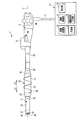
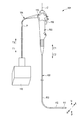
- FIG. 1 is a diagram illustrating an endoscope apparatus 1 that is an insertion apparatus according to the first embodiment.
- the endoscope apparatus 1 has a longitudinal axis C.
- One of the directions parallel to the longitudinal axis C (the direction of the arrow C1 in FIG. 1) is the proximal direction, and the opposite direction (the direction of the arrow C2 in FIG. 1) is the distal direction.
- the distal direction and the proximal direction are the longitudinal axis directions parallel to the longitudinal axis C.
- the endoscope apparatus 1 includes an insertion portion (endoscope insertion portion) 2 extending along the longitudinal axis C and an operation portion (endoscope operation portion) 3 provided on the proximal direction side from the insertion portion 2. And comprising.
- the insertion portion 2 extends along the longitudinal axis C and is inserted into the body cavity when the endoscope apparatus 1 is used.
- the peripheral unit 10 includes an image processing unit 11 such as an image processor, a light source unit 12 such as a lamp, a drive control unit 13, a drive operation input unit 15, and a display unit 16 such as a monitor.
- the drive control unit 13 is a control device including, for example, a CPU (Central Processing Unit), an ASIC (application specific integrated circuit), and the drive operation input unit 15 is, for example, a foot switch, an operation button, or the like.
- the insertion portion 2 includes a distal rigid portion 21 that forms the distal end of the insertion portion 2, an active bending portion 22 that is provided closer to the proximal direction than the distal rigid portion 21, and an active bending portion.
- a passive bending section (passive ⁇ bending section) 23 provided on the proximal direction side from 22 and a flexible tube section (flexible tube section) 25 provided on the proximal direction side from the passive bending portion 23.
- the active bending portion 22 and the passive bending portion 23 are connected by a bending tube connecting portion 26.
- the passive bending portion 23 and the serpentine tube portion 25 are connected by a relay connection portion 27.
- a cylindrical spiral unit 30 is provided on the outer peripheral side of the insertion portion 2.
- the spiral unit 30 extends along the longitudinal axis C between the bending tube connection portion 26 and the relay connection portion 27.
- the spiral unit 30 is attached to the insertion portion 2 in a state where the insertion portion 2 is inserted through the spiral unit 30.
- the spiral unit 30 rotates about the longitudinal axis with respect to the insertion portion 2 by transmitting a driving force. That is, the spiral unit 30 is an operating unit that is attached to the insertion unit 2 and operates by transmitting a driving force.
- the spiral unit 30 includes a base tube 31 extending along the longitudinal axis C.
- a fin portion 32 is provided on the outer peripheral surface of the base tube 31.
- the fin part 32 is spirally extended from the proximal direction to the distal direction.
- a distal side taper portion 33 is provided on the distal direction side of the base tube 31.
- the distal end side taper portion 33 is formed in a tapered shape whose outer diameter becomes smaller toward the distal direction side.
- a tubular proximal end side tapered portion 35 is provided on the proximal end side of the base tube 31.
- the proximal end side taper portion 35 is formed in a tapered shape having an outer diameter that decreases toward the proximal direction side.
- the spiral unit 30 rotates in one of the directions around the longitudinal axis, so that the insertion portion 2 has a propulsive force in the distal direction.
- a propulsive force in the proximal direction acts on the insertion portion 2.
- the pushing force in the distal direction improves the insertion property of the insertion portion 2 into the lumen
- the pushing force in the proximal direction improves the removal property of the insertion portion 2 from the lumen.
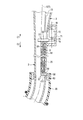
- FIG. 2 is a diagram showing a configuration for transmitting a driving force to the spiral unit 30.
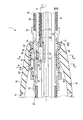
- FIG. 3 is a diagram illustrating a configuration in which the spiral unit 30 is attached to the insertion portion 2 in the relay connection portion 27.
- 4 is a cross-sectional view taken along line IV-IV in FIG. 3
- FIG. 5 is a cross-sectional view taken along line VV in FIG.
- a bending operation knob 36 for inputting a bending operation of the active bending portion 22 is provided on the outer surface of the operation portion 3.
- bending wires 37 ⁇ / b> A and 37 ⁇ / b> B extend along the longitudinal axis C in the insertion portion 2.
- the base ends of the bending wires 37A and 37B are connected to a pulley (not shown) connected to the bending operation knob 36.
- the distal ends of the bending wires 37 ⁇ / b> A and 37 ⁇ / b> B are connected to the distal end portion of the active bending portion 22.
- the respective bending wires 37A and 37B are inserted through the corresponding coils 38A and 38B.
- the base ends of the coils 38 ⁇ / b> A and 38 ⁇ / b> B are extended to the inside of the operation unit 3.
- the tips of the coils 38 ⁇ / b> A and 38 ⁇ / b> B are connected to the inner peripheral surface of the bending tube connecting portion 26.
- the two bending wires 37A and 37B are provided and the active bending portion 22 can be bent in two directions.
- four bending wires are provided and the active bending portion 22 is in four directions. It may be bendable.
- an imaging cable 41, a light guide 42, and a treatment instrument channel tube 43 are extended along the longitudinal axis C in the insertion portion 2.
- An imaging element (not shown) for imaging a subject is provided inside the distal end rigid portion 21 (the distal end portion of the insertion portion 2).
- the imaging element images a subject through the observation window 46.
- One end of the imaging cable 41 is connected to the imaging element.
- the imaging cable 41 extends through the insertion unit 2, the operation unit 3, and the universal cord 5, and the other end is connected to the image processing unit 11 of the peripheral unit 10. Image processing of the subject image picked up by the image processing unit 11 is performed, and a subject image is generated. Then, the generated image of the subject is displayed on the display unit 16.
- the light guide 42 extends through the inside of the insertion portion 2, the inside of the operation portion 3, and the inside of the universal cord 5, and is connected to the light source portion 12 of the peripheral unit 10.
- the light emitted from the light source unit 12 is guided by the light guide 42 and irradiated to the subject from the illumination window 47 of the distal end portion (the distal end rigid portion 21) of the insertion portion 2.
- a treatment instrument insertion section 48 into which a treatment instrument such as forceps is inserted is provided on the outer surface of the operation section 3.
- One end of the treatment instrument channel tube 43 is connected to the treatment instrument insertion portion 48 through the inside of the insertion portion 2 and the inside of the operation portion 3.
- the treatment instrument inserted from the treatment instrument insertion portion 48 passes through the inside of the treatment instrument channel tube 43 and protrudes from the opening 49 of the distal end rigid portion 21 toward the distal end. Then, the treatment with the treatment instrument is performed in a state where the treatment instrument protrudes from the opening 49 of the distal end rigid portion 21.
- the relay connection portion 27 is provided with a base member 51.
- a proximal end portion of the passive bending portion 23 is connected to a distal end portion of the base member 51 via a relay member 52.
- the passive bending portion 23 and the relay connection portion 27 are connected.
- the distal end portion of the serpentine tube portion 25 is connected to the proximal end portion of the base member 51 via the relay member 53. Thereby, the serpentine tube portion 25 and the relay connection portion 27 are connected.
- a hollow portion 55 is formed by the base member 51.
- the hollow portion 55 opens at the opening 56 toward the outer peripheral direction.
- a drive gear 57 and a relay gear 58 are attached to the base member 51.
- the drive gear 57 is disposed in the cavity 55, and the relay gear 58 is disposed in the vicinity of the opening 56 of the cavity 55.
- the drive gear 57 meshes with the relay gear 58.
- the drive gear 57 can rotate around the gear axis G1, and the relay gear 58 can rotate around the gear axis G2.
- a rotating cylindrical member 60 is attached to the base member 51 of the relay connection portion 27.
- the rotating cylindrical member 60 is attached to the base member 51 in a state where the insertion portion 2 is inserted through the rotating cylindrical member 60.
- the rotating cylindrical member 60 is rotatable in the direction around the longitudinal axis with respect to the insertion portion 2 (base member 51).
- An inner peripheral gear portion 61 is provided on the inner peripheral surface of the rotating cylindrical member 60 over the entire circumference in the direction around the longitudinal axis.
- the inner peripheral gear portion 61 meshes with the relay gear 58.
- three inner rollers 62A to 62C are attached to the rotating cylindrical member 60.
- the inner rollers 62A to 62C are arranged at substantially equal intervals in the direction around the longitudinal axis.
- Each inner roller 62A to 62C has a corresponding roller shaft (Q1 to Q3).
- Each of the inner rollers 62A to 62C is rotatable with respect to the rotating cylindrical member 60 about the corresponding roller shaft (Q1 to Q3). Further, the inner rollers 62A to 62C can rotate in the direction around the longitudinal axis with respect to the insertion portion 2 (base member 51) integrally with the rotating cylindrical member 60.
- a cylindrical cover member 63 is coated on the outer circumferential direction side of the rotating cylindrical member 60 and the inner rollers 62A to 62C.
- the front end of the cover member 63 is fixed to the base member 51 via a locking member 65A, and the base end of the cover member 63 is fixed to the base member 51 via a locking member 65B.
- the base member 51 and the cover member 63 are kept liquid-tight at the fixed position at the distal end of the cover member 63 and the fixed position at the proximal end of the cover member 63. This prevents the liquid from flowing into the cavity 55, the rotating cylindrical member 60, and the inner rollers 62A to 62C located on the inner circumferential direction side of the cover member 63.
- cover member 63 protrudes in the outer peripheral direction at a portion where the inner rollers 62A to 62C are located in the direction around the longitudinal axis. Note that the cover member 63 is fixed with respect to the insertion portion 2, and the rotating cylindrical member 60 and the inner rollers 62 A to 62 C are rotatable about the longitudinal axis with respect to the cover member 63.
- outer rollers 66A to 66F are attached to the inner peripheral surface of the proximal end side taper portion 35.
- the outer rollers 66A to 66F are located on the outer peripheral direction side of the cover member 63.
- the inner roller 62A is positioned between the outer roller 66A and the outer roller 66B, and the inner roller 62B is positioned between the outer roller 66C and the outer roller 66D.
- the inner roller 62C is located between the outer roller 66E and the outer roller 66F in the direction around the longitudinal axis.
- Each of the outer rollers 66A to 66F has a corresponding roller shaft (P1 to P6).
- Each of the outer rollers 66A to 66F is rotatable with respect to the cover member 63 and the proximal end side tapered portion 35 around the corresponding roller shaft (P1 to P6). Further, the outer rollers 66A to 66F can rotate around the longitudinal axis with respect to the insertion portion 2 (base member 51) integrally with the spiral unit 30.
- the inner roller 62A presses the outer roller 66A or the outer roller 66B.
- the inner roller 62B presses the outer roller 66C or the outer roller 66D
- the inner roller 62C presses the outer roller 66E or the outer roller 66F.
- the driving force is transmitted from the inner rollers 62A to 62C to the spiral unit 30, and the spiral unit 30 rotates in one of the directions around the longitudinal axis (in the direction around the longitudinal axis) with respect to the insertion portion 2 and the cover member 63.
- the inner rollers 62A to 62C rotate about the corresponding roller shafts (Q1 to Q3), so that the friction between the inner rollers 62A to 62C and the cover member 63 is reduced.
- the outer rollers 66A to 66F rotate about the corresponding roller shafts (P1 to P6), the friction between the outer rollers 66A to 66F and the cover member 63 is reduced. Therefore, the driving force is appropriately transmitted from the inner rollers 62A to 62C to the spiral unit 30, and the spiral unit 30 rotates appropriately.
- a motor housing 71 is connected to the operation unit 3.
- a motor 72 that is a drive member is accommodated in the motor housing 71.
- One end of a motor cable 73 is connected to the motor 72.
- the motor cable 73 extends through the operation unit 3 and the universal cord 5, and the other end is connected to the drive control unit 13 of the peripheral unit 10.
- the motor 72 is driven, and the motor shaft 75 rotates about the motor axis M.
- a driving force for operating (rotating) the spiral unit 30 that is the operating unit is generated.
- a relay gear 76 is attached to the motor shaft 75.
- a drive gear 77 that meshes with the relay gear 76 is provided inside the operation unit 3.
- the relay gear 76 can rotate around the motor shaft M integrally with the motor shaft 75.
- the driving force generated by the motor 72 is transmitted to the driving gear 77 via the relay gear 76.
- the drive gear 77 rotates about the gear shaft G3.
- a shaft 81 extends along the shaft axis S inside the serpentine tube portion 25 of the insertion portion 2.
- the shaft 81 has flexibility and extends from the first extending direction to the second extending direction.
- the first extending direction is the proximal direction
- the second extending direction is the distal direction.
- the base end (end on the first extending direction side) of the shaft 81 is connected to the drive gear 77.
- the rotational torque ⁇ acts on the shaft 81, and the shaft 81 rotates about the shaft axis S.
- the driving force for operating the spiral unit 30 is transmitted from the proximal direction (first extending direction) to the distal direction (second extending direction).
- the tip of the shaft 81 (end on the second extending direction side) is connected to the drive gear 57.
- the driving force for rotating the spiral unit 30 is transmitted from the shaft 81 to the driving gear 57 in the distal direction (second extending direction).
- the driving gear 57 rotates about the gear shaft G1.
- the relay gear 58 rotates about the gear shaft G ⁇ b> 2, and the driving force is transmitted to the rotating cylindrical member 60 via the relay gear 58.
- the spiral unit 30 which is an operation
- a flexible guide tube 82 is provided inside the flexible tube portion 25 from the proximal direction (first extending direction) to the distal direction (second extending direction). It is extended to.
- the distal end of the guide tube 82 is connected to the base member 51.
- the inside of the guide tube 82 communicates with the hollow portion 55.
- a shaft 81 is inserted into the guide tube 82. Therefore, the shaft 81 extends through the inside of the guide tube 82, and the outer peripheral portion of the shaft 81 is covered with the guide tube 82.
- the serpentine tube portion 25 includes a metal spiral tube (flex) 85, a metal mesh tube 86 coated on the outer circumferential direction side of the spiral tube 85, and an outer circumferential direction side of the mesh tube 86. And a resin snake tube outer skin 87 to be coated.
- the spiral tube 85 has a configuration in which a metal band extends in a spiral shape with the longitudinal axis C as the center, and has flexibility.
- the mesh tube 86 has a configuration in which metal is provided in a mesh shape and has flexibility.
- the serpentine skin 87 is made of a soft material and has flexibility. Therefore, the flexible tube portion 25 has flexibility and bends due to the action of an external force.
- the serpentine tube portion 25 is a variable shape tube that can be deformed by the action of an external force.
- a tube inner peripheral surface 89 that is an inner peripheral surface of the serpentine tube portion 25 is formed by the inner peripheral surface of the spiral tube 85.
- the serpentine tube portion 25 extends along the tube axis T from the proximal direction (first extending direction) to the distal direction (second extending direction).
- shaft T corresponds with the longitudinal axis C of the endoscope apparatus 1 (insertion part 2).
- the flexible tube portion 25, which is a shape-variable tube, returns elastically when bent at a tube bending radius Rt that is equal to or greater than the tube radius boundary value Rt0. That is, the bending of the serpentine tube portion 25 at the tube bending radius Rt equal to or greater than the tube radius boundary value Rt0 is elastic deformation.
- the flexible tube portion 25 does not return elastically when bent at a tube bending radius Rt smaller than the tube radius boundary value Rt0. That is, the bending of the serpentine tube portion 25 at the tube bending radius Rt smaller than the tube radius boundary value Rt0 is plastic deformation.
- FIG. 6 is a diagram showing the configuration of the shaft 81.
- the shaft 81 is formed by providing a plurality of layers (two layers in this embodiment) of cylindrical close-wound coils 90 ⁇ / b> A and 90 ⁇ / b> B.
- the corresponding linear members 91A and 91B are spirally extended about the shaft axis S.
- one of the directions around the shaft axis is defined as a first rotation direction (the direction of the arrow Y1 in FIG. 6), and the direction opposite to the first rotation direction is the second rotation direction (the direction of the arrow Y2 in FIG. 6).
- the linear member 91A moves in the first rotation direction from the proximal direction (the direction of the arrow C1 in FIG. 6) toward the distal direction (the direction of the arrow C2 in FIG. 6). Further, in the closely wound coil 90B, the linear member 91B moves in the second rotational direction as it goes from the proximal direction (first extending direction) to the distal direction (second extending direction).
- the tightly wound coils 90A and 90B are tightened between the first rotation state rotating in the first rotation direction and the second rotation state rotating in the second rotation direction.
- the state changes.
- the rigidity of the shaft 81 changes between the first rotation state and the second rotation state.
- the tightening state of the outermost layer tightly wound coil 90 ⁇ / b> B greatly affects the rigidity of the shaft 81.
- the first rotation state the tightening force by the closely wound coil 90B is reduced, and the rigidity of the shaft 81 is reduced.
- the second rotation state the tightening force by the closely wound coil 90B is increased, and the rigidity of the shaft 81 is increased. Therefore, the rigidity of the shaft 81 is lower in the first rotation state than in the second rotation state.
- the transmission performance of the driving force for rotating the spiral unit 30 is lower in the first rotation state than in the second rotation state.
- the shaft 81 since the shaft 81 has flexibility, it is deformed by the application of an external force.
- the shaft 81 When the shaft 81 is bent at a shaft bending radius Rs equal to or greater than the shaft radius boundary value Rs0, the shaft 81 returns elastically. That is, the bending of the shaft 81 at the shaft bending radius Rs equal to or greater than the shaft radius boundary value Rs0 is elastic deformation.
- the shaft 81 when the shaft 81 is bent at a tube bending radius Rs smaller than the shaft radius boundary value Rs0, the shaft 81 does not return elastically. That is, the bending of the shaft 81 at the shaft bending radius Rs smaller than the shaft radius boundary value Rs0 is plastic deformation.
- the driving force for rotating the spiral unit 30 cannot be transmitted. That is, in the state where the shaft 81 is plastically deformed, the driving force is not transmitted from the proximal direction (first extending direction) to the distal direction (second extending direction).
- FIG. 7 is a diagram showing the relationship between the rotational torque ⁇ applied to the shaft 81 and the shaft radius boundary value Rs0 of the shaft bending radius Rs.
- the shaft radius boundary value Rs ⁇ b> 0 is not limited to a single value, but changes according to the magnitude of the rotational torque ⁇ that rotates the shaft 81. Since the load applied to the shaft 81 increases as the rotational torque ⁇ increases, the shaft 81 is more easily plastically deformed. For this reason, the shaft radius boundary value Rs0 of the shaft bending radius Rs increases as the rotational torque ⁇ increases.
- the endoscope apparatus 1 that is the insertion apparatus of the present embodiment will be described.
- the insertion unit 2 is inserted into the lumen while the spiral unit 30 is attached to the insertion unit 2.
- the motor 72 is driven in a state where the fin portion 32 is in contact with the lumen wall, the driving force is transmitted to the shaft 81 as described above, and the shaft 81 rotates about the shaft axis S.
- the driving force is transmitted from the proximal direction (first extending direction) to the distal direction (second extending direction).
- the driving force is transmitted from the shaft 81 to the spiral unit 30, and the spiral unit 30 rotates with respect to the insertion portion 2 in one of the directions around the longitudinal axis (in the direction around the longitudinal axis).
- the spiral unit 30 is rotated in one direction around the longitudinal axis, so that a propulsive force in the distal direction or the proximal direction is applied to the insertion portion 2.
- FIG. 8 is a view showing a state in which the insertion portion 2 to which the spiral unit 30 is attached is inserted from the anus 201 into the large intestine 202.
- the insertion unit 2 when the endoscope apparatus 1 is used for observation of the large intestine 202, the insertion unit 2 is in a state where the spiral unit 30 located on the outer peripheral direction side of the passive bending portion 23 is located in the deep part of the large intestine 202. Is inserted.
- the splenic tube portion 25 is bent by an external force from the lumen wall at the splenic curve (splenic flexure) 203, the liver curve (hepatic flexure) 205 and the appendix 206 of the large intestine 202.
- the bending of the serpentine tube portion 25 in the spleen curve 203, the liver curve 205, and the appendix 206 is a deformation within the range of elastic deformation, and the serpentine tube portion 25 bends at a tube bending radius Rt equal to or greater than the tube radius boundary value Rt0. Therefore, the flexible tube 25 which is a shape-variable tube can be elastically restored even when it is bent by the spleen curve 203, the liver curve 205, and the appendix 206.
- FIG. 9 is a view showing a state in which the insertion portion 2 to which the spiral unit 30 is attached is inserted into the small intestine 213 from the mouth 210 through the esophagus 211 and stomach 212.
- the endoscope apparatus 1 may be used for an application different from the observation of the large intestine 202 shown in FIG. In this case, the insertion part 2 is inserted until the spiral unit 30 located on the outer peripheral direction side of the passive bending part 23 is located in the small intestine 213.
- the pharynx 215 between the mouth 210 and the esophagus 211 and the pylorus 217 between the stomach 212 and the duodenum 216 are caused by external force from the luminal wall by the external force from the lumen wall 25.
- the bending of the serpentine tube portion 25 at the pharynx 215 and the pylorus 217 is a deformation within the range of elastic deformation, and the serpentine tube portion 25 bends at a tube bending radius Rt equal to or greater than the tube radius boundary value Rt0. Accordingly, the flexible tube 25 which is a shape-variable tube can be elastically restored even when bent at the pharynx 215 and the pylorus 217.
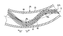
- FIG. 10 is a diagram illustrating an internal configuration of the flexible tube portion 25 in a state where the flexible tube portion 25 is bent within a range in which the elastic recovery is possible.
- FIG. 10 only the serpentine tube portion 25, the shaft 81, and the guide tube 82 are shown, and the imaging cable 41, the light guide 42, and the like are omitted.
- the tube bending radius Rt of the flexible tube portion 25 is equal to or greater than the tube radius boundary value Rt0.
- the shaft 81 is deformed within a range in which the elastic recovery is possible, and rotates around the shaft axis S without being deformed in a state in which the elastic recovery is impossible. Therefore, the shaft bending radius Rs of the shaft 81 is not less than the shaft radius boundary value Rs0. In other words, in a state where the flexible tube portion 25 which is a shape-variable tube is bent within a range where the elastic return can be performed, the shaft 81 rotates without being deformed to a state where the elastic return cannot be performed.
- the driving force for operating the spiral unit 30 is changed from the proximal direction (first extending direction) to the distal direction (first extending direction) in the state where the flexible tube portion 25 is bent within a range in which it can be elastically restored. 2nd extension direction) is transmitted appropriately. Therefore, even in a state where the flexible tube portion 25 is bent within a range in which the flexible tube portion 25 can be elastically restored, the driving force can be appropriately transmitted to the spiral unit 30 as the operation portion via the shaft 81.
- the shaft 81 has lower rigidity in the first rotation state rotating in the first rotation direction than in the second rotation state rotating in the second rotation direction. For this reason, in the 1st rotation state, compared with the 2nd rotation state, shaft 81 is easy to change and the transmissibility of driving force becomes low. In the present embodiment, even when the shaft 81 rotates in the first rotation state in which the rigidity is low, the shaft 81 is deformed into a state in which it cannot be elastically restored in a state in which the serpentine tube portion 25 is bent within a range in which it can be elastically restored. Without rotating in the first rotation direction.
- the driving force for operating the spiral unit 30 is driven from the proximal direction (first extending direction) in the shaft 81. It is possible to appropriately transmit in the distal direction (second extending direction). In such a configuration, in the second rotation state in which the transmission of driving force is high, the driving force is applied to the shaft 81 in the proximal direction (first direction) even when the flexible tube portion 25 is bent within a range in which it can be elastically restored. Of course, it is possible to appropriately transmit from the extending direction of 1) to the distal direction (second extending direction).
- the shaft radius boundary value Rs0 changes in accordance with the magnitude of the rotational torque ⁇ for rotating the shaft 81.
- the shaft 81 rotates without being deformed into a state in which it cannot be elastically restored in a state where the serpentine tube portion 25 is bent within a range where it can be elastically restored. To do.
- the driving force for operating the spiral unit 30 via the shaft 81 can be based on the bending of the serpentine tube portion 25 within the elastic return range. It is possible to appropriately transmit from the end direction (first extending direction) to the tip direction (second extending direction).
- FIG. 11 is a view showing a state in which a twist is generated in the shaft 81 extending inside the serpentine tube portion 25.
- the shaft 81 may be twisted due to the bending of the flexible tube portion 25 in a range where the elastic return can be performed.
- the shaft 81 extends from the proximal direction (first extending direction) to the distal direction (second extending direction) around the tube axis T (longitudinal axis C). Is spirally extended. In a portion where the shaft 81 is spirally extended, the shaft 81 is bent and the shaft 81 is deformed.
- the guide tube 82 contacts the tube inner peripheral surface 89 of the serpentine tube portion 25 in a state where the shaft bending radius Rs of the shaft 81 is equal to or larger than the shaft radius boundary value Rs0. That is, the guide tube 82 contacts the tube inner peripheral surface 89 of the serpentine tube portion 25 while the shaft 81 is deformed within a range in which the shaft 81 can be elastically restored.
- a pressing force is applied from the tube inner peripheral surface 89 toward the tube axis T to the shaft 81 extending inside the guide tube 82.
- the shaft bending radius Rs of the shaft 81 is maintained at a magnitude equal to or larger than the shaft radius boundary value Rs0.
- the shaft 81 is deformed within a range where it can be elastically restored, and is not plastically deformed. Therefore, even when the shaft 81 is twisted, the driving force for operating the spiral unit 30 is appropriate from the proximal direction (first extending direction) to the distal direction (second extending direction) in the shaft 81. Is transmitted to. Therefore, even when the shaft 81 is twisted, the driving force can be appropriately transmitted to the spiral unit 30 that is the operating portion via the shaft 81.
- FIG. 12 is a diagram illustrating an endoscope apparatus 101 that is an insertion apparatus according to the present embodiment.
- the endoscope apparatus 101 has a longitudinal axis C ′.
- One of the directions parallel to the longitudinal axis C ′ is the proximal direction (the direction of the arrow C′1 in FIG. 12), and the opposite direction to the proximal direction is the distal direction (the direction of the arrow C′2 in FIG. 12). ).
- the endoscope apparatus 101 includes an insertion portion (endoscope insertion portion) 102 extending along the longitudinal axis C ′, and an operation portion (endoscope operation portion) provided on the proximal side from the insertion portion 102. 103.
- the insertion portion 102 extends along the longitudinal axis C ′ and is inserted into the body cavity when the endoscope apparatus 101 is used.
- One end of a universal cord 105 is connected to the operation unit 103.
- the universal cord 105 extends along the tube axis T ′ from the first extending direction to the second extending direction.
- the other end of the universal cord 105 is connected to a peripheral unit 110.
- one of the directions parallel to the tube axis T ′ is the first extending direction (the direction of the arrow T ′ 1 in FIG. 12), and the direction opposite to the first extending direction is the second extending direction.
- Direction (direction of arrow T′2 in FIG. 12).
- the first extending direction is a direction toward the peripheral unit 110
- the second extending direction is a direction toward the operation unit 103.
- the insertion portion 102 includes a distal end rigid portion 111 that forms the distal end of the insertion portion 102, a bending section 112 provided on the proximal direction side from the distal end rigid portion 111, and a proximal end side from the bending portion 112. And a serpentine tube portion 113 to be provided.
- the bending portion 112 performs a bending operation when the driving force is transmitted.
- the bending portion 112 is an operating portion that is provided in the insertion portion 2 and operates when a driving force is transmitted.
- the bending portion 112 can be bent in the bending UD direction (the direction of the arrow U and the direction of the arrow D in FIG. 12) and the bending LR direction (the direction of the arrow L and the direction of the arrow R in FIG. 12).
- an imaging cable (41), a light guide (42), and the like are provided, and the peripheral unit 110 includes an image processing unit (11), a light source unit (12), and the like. Is provided. Since these portions are the same as those in the first embodiment, detailed description thereof is omitted. In the following description, the configuration for operating the bending portion 112 will be specifically described.
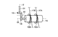
- FIG. 13 is a diagram showing a configuration for transmitting a driving force to the bending portion 112.
- the operation unit 103 is provided with a bending operation knob 115.
- a driving force for bending the bending portion 112 in one of the bending UD directions is generated.
- a UD pulley 116 ⁇ / b> A is provided inside the operation unit 3.
- the proximal ends of the UD bending wires 117U and 117D are connected to the UD pulley 116A.
- the UD pulley 116A is turned.
- the UD pulley 116A rotates, the UD bending wires 117U and 117D move along the longitudinal axis C ′, and the UD bending wire 117U or the UD bending wire 117D is pulled in the proximal direction.
- the distal ends of the UD bending wires 117U and 117D are connected to the distal end portion of the bending portion 112.
- the driving force generated by the bending operation knob 115 is transmitted to the bending portion 112 via the UD pulley 116A and the UD bending wires 117U and 117D.
- the bending portion 112 performs a bending operation and is bent in one of the bending UD directions (in the bending UD direction).
- the operation unit 103 is provided with a bending operation dial 119.
- a bending operation for bending the bending portion 112 in one of the bending LR directions is input by the bending operation dial 119.
- a detection unit 121 that detects an input of a bending operation with the bending operation dial 119 is provided inside the operation unit 3.
- One end of an electric signal line 122 is connected to the detection unit 121.
- the other end of the electric signal line 122 is connected to the drive control unit 123 of the peripheral unit 110 through the inside of the universal cord 105.
- the drive control unit 123 is a control device including a CPU and an ASIC, for example.
- a motor 125 as a driving member is provided at the end of the universal cord 105 on the first extending direction side.
- the motor 125 is electrically connected to the drive control unit 123 via the electric wiring 126.
- the drive control unit 123 supplies power to the motor 125 based on the detection result of the detection unit 121.
- the motor 125 is driven, and the motor shaft 127 rotates about the motor shaft M ′.
- a driving force for operating the bending portion 112 that is the operation portion (bending in one direction in the bending LR direction) is generated.
- a relay gear 128 is attached to the motor shaft 127.
- a driving gear 129 that meshes with the relay gear 128 is provided inside the universal cord 105.
- the relay gear 128 can rotate around the motor shaft M ′ integrally with the motor shaft 127.
- the driving force generated by the motor 125 is transmitted to the driving gear 129 via the relay gear 128.
- the drive gear 129 rotates about the gear shaft G4.
- a shaft 131 is extended along the shaft axis S ′.
- the shaft 131 is flexible and extends from the first extending direction (the direction of the arrow T′1 in FIG. 13) to the second extending direction (the direction of the arrow T′2 in FIG. 13). ing.
- One end (end on the first extending direction side) of the shaft 131 is connected to the drive gear 129.
- the driving force for bending the bending portion 112 is generated by the motor 125, the driving force is transmitted to the shaft 131 from the first extending direction via the relay gear 128 and the driving gear 129.
- the rotational torque ⁇ ′ acts on the shaft 131, and the shaft 131 rotates about the shaft axis S ′.
- a driving force for operating the bending portion 112 is transmitted from the first extending direction to the second extending direction.
- a flexible guide tube 132 is extended from the first extending direction to the second extending direction.
- a shaft 131 is inserted into the guide tube 132. Therefore, the shaft 131 extends through the inside of the guide tube 132, and the outer peripheral portion of the shaft 131 is covered with the guide tube 132.
- a bevel gear 133 is provided inside the operation unit 103.
- the other end (end on the second extending direction side) of the shaft 131 is connected to the bevel gear 133.
- the driving force for bending the bending portion 112 is transmitted from the shaft 131 to the bevel gear 133 in the second extending direction.
- the bevel gear 133 includes a relay gear (first gear) 135 that rotates about the gear axis G5 when a driving force is transmitted through the shaft 131.
- a spur gear (second gear) 136 that meshes with the relay gear 135 is provided inside the operation unit 103.
- the number of spur gears 136 is greater than the number of gears of the relay gear 135. For this reason, when the driving force is transmitted from the relay gear 135, the spur gear 136 rotates around the gear shaft G6 at a rotational angular velocity smaller than that of the relay gear 135. As a result, the driving force for bending the bending portion 112 is amplified between the relay gear (first gear) 135 and the spur gear 136 (second gear). Therefore, the relay gear 135 and the spur gear 136 serve as an amplifying unit 137 that amplifies the driving force transmitted from the shaft 131 in the second extending direction.
- LR pulley 116B is provided inside the operation unit 103.
- the base ends of the LR bending wires 117L and 117R are connected to the LR pulley 116B.
- the spur gear 136 rotates, the driving force generated by the motor 125 is transmitted to the LR pulley 116B, and the LR pulley 116B rotates.
- the LR pulley 116B rotates, the LR bending wires 117L and 117R move along the longitudinal axis C ′, and the LR bending wire 117L or the LR bending wire 117R is pulled in the proximal direction.
- the distal ends of the LR bending wires 117L and 117R are connected to the distal end portion of the bending portion 112.
- the driving force transmitted from the motor 125 to the spur gear 136 is transmitted to the bending portion 112 via the LR pulley 116B and the LR bending wires 117L and 117R.
- the bending portion 112 performs a bending operation and bends in one direction of the bending LR direction (in the bending LR direction). That is, when the driving force generated by the motor 125 is transmitted, the bending portion 112 as the operation portion operates.
- FIG. 14 is a diagram illustrating a configuration of the universal code 105.
- the universal cord 105 includes a metal spiral tube (flex) 141, a metal mesh tube 142 coated on the outer circumferential direction side of the spiral tube 141, and an outer circumferential direction side of the mesh tube 142.
- the spiral tube 141 has a configuration in which a metal band extends spirally around the tube axis T ′, and has flexibility.
- the mesh tube 142 has a configuration in which a metal is provided in a mesh shape, like the mesh tube 86 of the first embodiment, and has flexibility.
- the cord skin 143 is formed of a soft material and has flexibility, like the snake tube skin 87 of the first embodiment. Therefore, the universal cord 105 has flexibility and bends by the action of an external force. That is, the universal cord 105 is a variable shape tube that can be deformed by the action of an external force. Further, a tube inner peripheral surface 145 that is an inner peripheral surface of the universal cord 105 is formed by the inner peripheral surface of the spiral tube 141.
- the universal cord 105 which is a shape-variable tube, returns elastically when bent at a tube bending radius R't that is equal to or greater than the tube radius boundary value R't0, as in the case of the serpentine tube portion 25 of the first embodiment. That is, the bending of the universal cord 105 at the tube bending radius R′t equal to or greater than the tube radius boundary value R′t0 is elastic deformation. On the other hand, the bending of the universal cord 105 at the tube bending radius R′t smaller than the tube radius boundary value R′t0 is plastic deformation.
- the shaft 131 is formed in the same manner as the shaft 81 of the first embodiment. For this reason, in the shaft 131, similarly to the shaft 81 of the first embodiment, between the first rotation state rotating in the first rotation direction and the second rotation state rotating in the second rotation direction.
- the rigidity of the shaft 131 changes. That is, the rigidity of the shaft 131 is lower in the first rotation state than in the second rotation state. Due to the lower rigidity of the shaft 131, the transmission performance of the driving force for bending the bending portion 112 is lower in the first rotation state than in the second rotation state.
- the shaft 131 since the shaft 131 has flexibility, it is deformed when an external force is applied. As with the shaft 81 of the first embodiment, the shaft 131 returns elastically when bent at a shaft bending radius R ′s that is equal to or greater than the shaft radius boundary value R′s0. That is, the bending of the shaft 131 at the shaft bending radius R ′s equal to or greater than the shaft radius boundary value R′s0 is elastic deformation. On the other hand, the bending of the shaft 131 at the shaft bending radius R ′s smaller than the shaft radius boundary value R′s0 is plastic deformation. When the shaft 131 is plastically deformed, the driving force for bending the bending portion 112 cannot be transmitted.
- the shaft radius boundary value R's0 is not limited to one value, but corresponds to the magnitude of the rotational torque ⁇ 'that rotates the shaft 131. And change.
- the insertion unit 102 is inserted into the lumen.
- a driving force for bending the bending portion 112 is generated by rotating the bending operation knob 115.
- the generated driving force is transmitted to the bending portion 112 via the UD pulley 116A and the UD bending wires 117U and 117D.
- the bending portion 112 is bent in one of the bending UD directions (in the bending UD direction).
- the bending portion 112 is bent in one direction in the bending LR direction, the bending operation is input by the bending operation dial 119.
- the detection unit 121 detects an input of the bending operation, and power is supplied from the drive control unit 123 to the motor 125.
- the motor 125 is driven, the driving force is transmitted to the shaft 131 as described above, and the shaft 131 rotates about the shaft axis S ′.
- the driving force is transmitted from the first extending direction to the second extending direction.
- the driving force is transmitted from the shaft 81 to the bending portion 112 via the LR pulley 116B and the LR bending wires 117L and 117R.
- the bending portion 112 is bent in one of the bending LR directions (in the bending LR direction).
- FIG. 15 is a diagram illustrating an extended state of the universal cord 105 from the peripheral unit 110 when the endoscope apparatus 101 is used.
- the universal cord 105 that is a shape-variable tube may hang down between the peripheral unit 110 and the operation unit 103 due to gravity that is an external force.
- the universal cord 105 bends at the sagging portion.
- the bending of the universal cord 105 at the sagging portion is a deformation in the range of elastic deformation, and the universal cord 105 is bent at a tube bending radius R′t that is equal to or greater than the tube radius boundary value R′t0. Therefore, the universal cord 105, which is a shape-variable tube, can be elastically restored even when it is bent at the hanging portion.
- FIG. 16 is a diagram illustrating an extended state of the universal cord 105 from the operation unit 103 in a state where the endoscope apparatus 101 is used.
- the operator may rotate the insertion unit 102 and the operation unit 103 about the longitudinal axis C.
- an external force is applied to the universal cord 105 connected to the end of the second extending direction side on the operating unit 103, and the universal cord 105 is connected to the end of the second extending direction side.
- the bending of the universal cord 105 at the end portion on the second extending direction side is a deformation within a range of elastic deformation, and the universal cord 105 has a tube bending radius R′t equal to or greater than the tube radius boundary value R′t0. Bend. Therefore, the universal cord 105 that is a shape-variable tube can be elastically restored even when it is bent in the vicinity of the operation unit 103.
- the universal cord 105 that is a shape-variable tube may be bent within a range in which the elastic return can be performed.
- the tube bending radius R′t of the universal cord 105 is equal to or greater than the tube radius boundary value R′t0.
- the shaft 131 in the state where the universal cord 105 that is a shape-variable tube is bent within a range in which the elastic return can be performed, the shaft 131 is deformed in a range in which the elastic return is possible, and is elastic. It rotates around the shaft axis S without being deformed in a state where it cannot be restored. Therefore, the shaft bending radius R ′s of the shaft 131 is not less than the shaft radius boundary value R′s0.
- the driving force for operating the bending portion 112 is appropriate in the shaft 131 from the first extending direction to the second extending direction. Is transmitted to. Therefore, even when the universal cord 105 is bent within a range in which the universal cord 105 can be elastically restored, the driving force can be appropriately transmitted to the bending portion 112 as the operation portion via the shaft 131.
- the shaft 131 even when the shaft 131 rotates in the first rotation state in which the rigidity is low, the shaft 131 remains in a state where the universal cord 105 is bent within a range in which it can be elastically restored. Rotates in the first rotational direction without being deformed into a state where it cannot be elastically restored. Therefore, even when the universal cord 105 is bent within a range in which the shaft 131 can be elastically restored in the first rotation state of the shaft 131, the driving force for operating the bending portion 112 via the shaft 131 is changed from the first extending direction to the second extension direction. Proper transmission in the extending direction is possible.
- the shaft 131 is elastic in a state where the universal cord 105 is bent within a range in which the universal cord 105 can be elastically restored regardless of the magnitude of the rotational torque ⁇ ′ acting on the shaft 131. Rotates without deforming into a non-recoverable state. Therefore, regardless of the magnitude of the rotational torque ⁇ ′ acting on the shaft 131, the first driving force in the shaft 131 is used to operate the bending portion 112 in a state where the flexible tube portion 25 is bent within a range in which it can be elastically restored. Can be appropriately transmitted from the extending direction to the second extending direction.
- an amplification unit 137 that amplifies the driving force transmitted by the shaft 131 is provided.
- the amplification unit 137 By providing the amplification unit 137 in a portion closer to the bending portion 112 that is the operation portion than the shaft 131, it is possible to reduce the rotational torque ⁇ ′ that acts on the shaft 131. Thereby, the load at the time of the shaft 131 rotating can be made small.
- the tube inner peripheral surface 145 of the universal cord 105 is pushed toward the shaft 131 toward the tube axis T ′ in the state where the shaft 131 is twisted, similarly to the tube inner peripheral surface 89 of the first embodiment. Pressure is applied.
- the shaft bending radius R's of the shaft 131 is maintained at a magnitude equal to or larger than the shaft radius boundary value Rs'0. As a result, even when the shaft 131 is twisted, the shaft 131 is deformed within a range in which it can be elastically restored and is not plastically deformed.
- the driving force for operating the bending portion 112 is appropriately transmitted from the first extending direction to the second extending direction in the shaft 131. Therefore, even when the shaft 131 is twisted, the driving force can be appropriately transmitted to the bending portion 112 that is the operating portion via the shaft 131.
- the driving force is generated by the motor 125 that is an electric motor only when the bending portion 112 is bent in the bending LR direction, but the present invention is not limited to this. That is, when the bending portion 112 is bent in the bending UD direction, the driving force may be generated by an electric motor (not shown) having the same configuration as the motor 125.
- the driving force for bending the bending portion 112 in the bending UD direction is transmitted to the bending portion 112 by the same configuration as that for transmitting the driving force for bending the bending portion 112 in the bending LR direction in the second embodiment. Is done.
- FIG. 17 is a diagram illustrating a configuration for transmitting a driving force to the bending portion 112 in the endoscope apparatus 101 of the present modification.
- the bending portion 112 when the driving force is transmitted to the bending portion 112, the bending portion 112 is one direction perpendicular to the longitudinal axis C, or a direction opposite to the first bending direction.
- the bending operation is performed in the second bending direction.
- a bending operation joystick 151 is provided instead of the bending operation dial 119. By tilting the bending operation joystick 151, a bending operation for bending the bending portion 112 in the first bending direction or the second bending direction is input.
- the driving force for bending the bending portion 112 is generated by driving the motor 125.
- the driving force generated by the motor 125 is transmitted to the shaft 131 via the relay gear 128 and the driving gear 129, and the driving force is transmitted from the first extending direction to the second extending direction on the shaft 131.
- the driving force is transmitted to the pulley 116 via the bevel gear 133 and the spur gear 136.
- the motor 125 is always driven when the endoscope apparatus 101 is used. Therefore, the driving force from the motor 125 is constantly transmitted to the pulley 116. For this reason, the pulley 116 is always rotating.
- FIG. 18 is a diagram showing an extended state of the bending wires 117A and 117B.
- the distal ends of the bending wires 117 ⁇ / b> A and 117 ⁇ / b> B are connected to the distal end portion of the bending portion 112.
- the proximal ends of the bending wires 117A and 117B are not connected to the pulley 116.
- C rings 152 ⁇ / b> A and 152 ⁇ / b> B are provided inside the operation unit 103.
- the respective bending wires 117A and 117B are wound around the outer peripheral surfaces of the corresponding C-rings 152A and 152B.
- the base ends of the respective bending wires 117A and 117B wound around the corresponding C rings 152A and 152B are connected to the plate-like portion 153.
- the plate-like portion 153 tilts integrally with the bending operation joystick 151 by an input of the bending operation. As the plate-like portion 153 tilts, the bending wire 117A or the bending wire 117B is pulled in the proximal direction.
- FIG. 19 is a diagram showing the configuration of the pulley 116 and the C-rings 152A and 152B.
- the C rings 152 ⁇ / b> A and 152 ⁇ / b> B are provided so as to cover the outer peripheral portion of the pulley 116.
- the C rings 152A and 152B are not in contact with the pulley 116. For this reason, the driving force transmitted from the motor 125 to the pulley 116 is not transmitted to the bending wires 117A and 117B.
- the bending force of the bending portion 112 in the first bending direction or the second bending direction is assisted by the driving force transmitted to the pulley 116. Is done. Also in this modification, it has an effect
- the first bending direction and the second bending direction coincide with the bending UD direction, and in another embodiment, the first bending direction and the second bending direction are in the bending LR direction. Matches.
- the guide tube (82; 132) that covers the outer periphery of the shaft (81; 131) is provided, but the guide tube (82; 132) is not necessarily provided.
- the operation unit is not limited to the spiral unit 30 and the bending unit 112.
- the variable shape tube is not limited to the serpentine tube portion 25 and the universal cord 105.
- the endoscope apparatus (1; 101) is described as an example of the insertion apparatus, but the insertion apparatus is not limited to the endoscope apparatus (1; 101).
- the above-described configuration may be applied to an insertion portion of a manipulator device that is an insertion device.
- the variable shape tube (25; 105) has a tube shaft (T; T) extending from the first extending direction (C1; T′1) to the second extending direction (C2; T′2). ′) And has flexibility.
- the shape-variable tube (25; 105) returns elastically when it is bent at a tube bending radius (Rt; R't) equal to or greater than the tube radius boundary value (Rt0; R't0).
- the shaft (81; 131) extends from the first extending direction (C1; T′1) to the second extending direction (C2; T′2) inside the variable shape tube (25; 105). It has a shaft axis (S; S ′) and is rotated about the shaft axis (S; S ′) by the action of rotational torque ( ⁇ ; ⁇ ′), thereby moving the operating part (30; 112).
- the driving force to be operated is transmitted from the first extending direction (C1; T′1) to the second extending direction (C2; T′2).
- the shaft (81; 131) When the shaft (81; 131) is bent at a shaft bending radius (Rs; R's) that is equal to or greater than the shaft radius boundary value (Rs0; R's0), the shaft (81; 131) is elastically restored to the shape variable tube (25; 105). Rotates without deformation in a state where it cannot be elastically restored in a state where it is bent within a range where it can be elastically restored.
Landscapes
- Health & Medical Sciences (AREA)
- Life Sciences & Earth Sciences (AREA)
- Surgery (AREA)
- Biomedical Technology (AREA)
- Medical Informatics (AREA)
- Optics & Photonics (AREA)
- Pathology (AREA)
- Radiology & Medical Imaging (AREA)
- Biophysics (AREA)
- Engineering & Computer Science (AREA)
- Physics & Mathematics (AREA)
- Heart & Thoracic Surgery (AREA)
- Nuclear Medicine, Radiotherapy & Molecular Imaging (AREA)
- Molecular Biology (AREA)
- Animal Behavior & Ethology (AREA)
- General Health & Medical Sciences (AREA)
- Public Health (AREA)
- Veterinary Medicine (AREA)
- Gastroenterology & Hepatology (AREA)
- Endoscopes (AREA)
- Instruments For Viewing The Inside Of Hollow Bodies (AREA)
Abstract
Description
本発明の第1の実施形態について、図1乃至図11を参照して説明する。図1は、第1の実施形態に係る挿入装置である内視鏡装置1を示す図である。図1に示すように、内視鏡装置1は、長手軸Cを有する。長手軸Cに平行な方向の一方(図1の矢印C1の方向)が基端方向であり、基端方向とは反対方向(図1の矢印C2の方向)が先端方向である。そして、先端方向及び基端方向が長手軸Cに平行な長手軸方向となる。内視鏡装置1は、長手軸Cに沿って延設される挿入部(内視鏡挿入部)2と、挿入部2より基端方向側に設けられる操作部(内視鏡操作部)3と、を備える。挿入部2は、長手軸Cに沿って延設され、内視鏡装置1の使用時には体腔内に挿入される。
第1の実施形態では、蛇管部25の内部に延設されるシャフト81を回転させることにより、動作部であるスパイラルユニット30を動作させる駆動力が伝達されるが、本発明の別の適用例である第2の実施形態を、図12乃至図16を参照して説明する。図12は、本実施形態の挿入装置である内視鏡装置101を示す図である。
また、第2の実施形態と同様に、湾曲部112が動作部となり、形状可変チューブであるユニバーサルコード105の内部にシャフト131が延設される適用例として、図17乃至図19を参照して説明する第1の変形例がある。なお、第1の変形例では、第2の実施形態と同一の部分については、同一の参照符号を付し、その説明は省略する。
Claims (10)
- 長手軸に沿って延設される挿入部と、
前記挿入部に設けられるか、又は、前記挿入部に取付けられ、駆動力が伝達されることにより動作する動作部と、
第1の延設方向から前記第1の延設方向とは反対方向である第2の延設方向へ延設されるチューブ軸を有し、可撓性を有する形状可変チューブであって、チューブ半径境界値以上のチューブ曲げ半径で曲がった場合に弾性復帰する形状可変チューブと、
前記形状可変チューブの内部において前記第1の延設方向から前記第2の延設方向へ延設されるシャフト軸を有し、回転トルクの作用によって前記シャフト軸を中心として回転することにより、前記動作部を動作させる前記駆動力を前記第1の延設方向から前記第2の延設方向へ伝達するシャフトであって、シャフト半径境界値以上のシャフト曲げ半径で曲がった場合に弾性復帰し、前記形状可変チューブが弾性復帰可能な範囲で曲がった状態において、弾性復帰不可能な状態に変形することなく回転するシャフトと、
を具備する挿入装置。 - 前記シャフトの前記シャフト曲げ半径の前記シャフト半径境界値の大きさは、前記シャフトを回転させる前記回転トルクの大きさに対応して変化し、
前記シャフトは、前記回転トルクの前記大きさに関係なく、前記形状可変チューブが弾性復帰可能な範囲で曲がった状態において、弾性復帰不可能な状態に変形することなく回転する、
請求項1の挿入装置。 - 前記形状可変チューブは、前記シャフトに前記回転トルクが作用することによって螺旋状に延設される前記シャフトが回転する状態において、前記シャフトに前記チューブ軸へ向かって押圧力を作用させることにより、前記シャフトの前記シャフト曲げ半径を前記シャフト半径境界値以上の大きさで維持するチューブ内周面を備える、請求項1の挿入装置。
- 前記シャフトは、シャフト軸回り方向の一方である第1の回転方向に回転する第1の回転状態において、前記第1の回転方向とは反対方向である第2の回転方向に回転する第2の回転状態より、剛性が低く、かつ、前記駆動力の伝達性が低くなり、
前記第1の回転状態の前記シャフトは、前記形状可変チューブが弾性復帰可能な範囲で曲がった状態において、弾性復帰不可能な状態に変形することなく前記第1の回転方向へ回転する、
請求項1の挿入装置。 - 前記動作部を動作させる前記駆動力を発生し、発生した前記駆動力を第1の延設方向から前記シャフトに伝達することにより、前記シャフトに前記回転トルクを作用させる駆動部材をさらに具備する、請求項1の挿入装置。
- 前記シャフトから前記第2の延設方向に向かって伝達された前記駆動力を増幅する増幅ユニットをさらに具備する、請求項1の挿入装置。
- 前記増幅ユニットは、前記シャフトを介して前記駆動力が伝達されることにより回転する第1のギアと、前記第1のギアと噛合い、前記第1のギアから前記駆動力が伝達されることにより、前記第1のギアより小さい回転角速度で回転する第2のギアと、を備える、請求項6の挿入装置。
- 前記形状可変チューブの内部に前記第1の延設方向から前記第2の延設方向へ延設され、内部に前記シャフトが挿通されるガイドチューブであって、前記シャフトの外周部を覆うガイドチューブをさらに具備する、請求項1の挿入装置。
- 前記形状可変チューブは、前記チューブ軸が前記長手軸と同軸になる状態で前記挿入部に設けられる蛇管部であって、前記第1の延設方向が基端方向となり、前記第2の延設方向が先端方向となる蛇管部であり、
前記シャフトは、前記蛇管部の内部に前記基端方向から前記先端方向に向かって延設され、
前記動作部は、前記基端方向から前記先端方向へ螺旋状に延設されるフィン部を備え、前記挿入部の外周方向側に取付けられる筒状のスパイラルユニットであって、前記シャフトの回転によって前記駆動力が伝達されることにより、長手軸回り方向に回転し、前記フィン部が内周方向に押圧された状態で回転することにより、前記挿入部に前記先端方向又は前記基端方向への推進力を作用させるスパイラルユニットである、
請求項1の挿入装置。 - 前記挿入部の基端方向側に設けられる操作部と、
前記操作部の内部に設けられるプーリと、
前記挿入部の内部に前記長手軸に沿って延設され、基端が前記プーリに接続される湾曲ワイヤであって、前記プーリが回転することにより、前記長手軸に沿って移動する湾曲ワイヤと、
をさらに具備し、
前記動作部は、前記湾曲ワイヤの先端が接続される状態で前記挿入部に設けられ、前記湾曲ワイヤの前記長手軸に沿った移動によって前記駆動力が伝達されることにより、湾曲する湾曲部であり、
前記形状可変チューブは、第2の延設方向側の端が前記操作部に接続されるユニバーサルコードであり、
前記シャフトは、前記ユニバーサルコードの内部で回転することにより、前記駆動力を前記プーリに伝達し、前記プーリを回転させる、
請求項1の挿入装置。
Priority Applications (4)
| Application Number | Priority Date | Filing Date | Title |
|---|---|---|---|
| EP14834306.4A EP3031384A4 (en) | 2013-08-06 | 2014-05-21 | Insertion device |
| JP2015501603A JP5750622B1 (ja) | 2013-08-06 | 2014-05-21 | 挿入装置 |
| CN201480044518.3A CN105473046B (zh) | 2013-08-06 | 2014-05-21 | 插入装置 |
| US15/016,749 US10736493B2 (en) | 2013-08-06 | 2016-02-05 | Inserting device |
Applications Claiming Priority (2)
| Application Number | Priority Date | Filing Date | Title |
|---|---|---|---|
| JP2013-163202 | 2013-08-06 | ||
| JP2013163202 | 2013-08-06 |
Related Child Applications (1)
| Application Number | Title | Priority Date | Filing Date |
|---|---|---|---|
| US15/016,749 Continuation US10736493B2 (en) | 2013-08-06 | 2016-02-05 | Inserting device |
Publications (1)
| Publication Number | Publication Date |
|---|---|
| WO2015019675A1 true WO2015019675A1 (ja) | 2015-02-12 |
Family
ID=52461023
Family Applications (1)
| Application Number | Title | Priority Date | Filing Date |
|---|---|---|---|
| PCT/JP2014/063486 WO2015019675A1 (ja) | 2013-08-06 | 2014-05-21 | 挿入装置 |
Country Status (5)
| Country | Link |
|---|---|
| US (1) | US10736493B2 (ja) |
| EP (1) | EP3031384A4 (ja) |
| JP (1) | JP5750622B1 (ja) |
| CN (1) | CN105473046B (ja) |
| WO (1) | WO2015019675A1 (ja) |
Cited By (9)
| Publication number | Priority date | Publication date | Assignee | Title |
|---|---|---|---|---|
| WO2016194453A1 (ja) * | 2015-06-05 | 2016-12-08 | オリンパス株式会社 | 挿入装置 |
| WO2016203802A1 (ja) * | 2015-06-18 | 2016-12-22 | オリンパス株式会社 | 駆動シャフト、挿入機器および挿入装置 |
| WO2017037723A1 (en) * | 2015-09-04 | 2017-03-09 | Memic Innovative Surgery Ltd. | Actuation of a device comprising mechanical arms |
| US9788911B2 (en) | 2014-09-04 | 2017-10-17 | Memic Innovative Surgery Ltd. | Method and devices for hysterectomy |
| US10299866B2 (en) | 2017-03-09 | 2019-05-28 | Memic Innovative Surgery Ltd. | Multiple-joint input arm for control of a surgical mechanical arm |
| US10463438B2 (en) | 2016-03-09 | 2019-11-05 | Memic Innovative Surgery Ltd. | Modular device comprising mechanical arms |
| WO2020012562A1 (ja) * | 2018-07-10 | 2020-01-16 | オリンパス株式会社 | 医療用回転機構および内視鏡装置 |
| CN112074222A (zh) * | 2018-05-16 | 2020-12-11 | 奥林巴斯株式会社 | 内窥镜的驱动力传递机构 |
| US11779410B2 (en) | 2017-03-09 | 2023-10-10 | Momentis Surgical Ltd | Control console including an input arm for control of a surgical mechanical arm |
Families Citing this family (13)
| Publication number | Priority date | Publication date | Assignee | Title |
|---|---|---|---|---|
| WO2017073198A1 (ja) | 2015-10-27 | 2017-05-04 | オリンパス株式会社 | 挿入装置 |
| EP3369358A4 (en) | 2015-10-28 | 2019-06-26 | Olympus Corporation | inserter |
| CN109068952B (zh) * | 2016-06-13 | 2020-11-13 | 奥林巴斯株式会社 | 插入设备、安装器具以及驱动力传递单元 |
| CN109414152B (zh) * | 2016-08-02 | 2021-05-11 | 奥林巴斯株式会社 | 插入装置 |
| WO2018034021A1 (ja) * | 2016-08-19 | 2018-02-22 | オリンパス株式会社 | 内視鏡 |
| WO2018127975A1 (ja) * | 2017-01-06 | 2018-07-12 | 株式会社オグラ | 油圧作動装置およびトルク伝達用連結具 |
| KR102090363B1 (ko) * | 2017-03-06 | 2020-03-17 | 한양대학교 에리카산학협력단 | 연성 메커니즘 |
| JP6995659B2 (ja) * | 2018-02-14 | 2022-01-14 | 株式会社フジクラ | 撮像モジュール、内視鏡、及びカテーテル |
| KR102110353B1 (ko) * | 2018-04-18 | 2020-05-14 | (주) 태웅메디칼 | 분리형 프로브를 갖는 내시경 |
| USD974555S1 (en) * | 2019-09-13 | 2023-01-03 | Olympus Corporation | Endoscope operating unit |
| USD974556S1 (en) * | 2019-09-13 | 2023-01-03 | Olympus Corporation | Endoscope operating unit |
| CN110727365B (zh) * | 2019-09-17 | 2023-10-10 | 苏州佳世达电通有限公司 | 用具插置结构及电子装置 |
| US11933765B2 (en) * | 2021-02-05 | 2024-03-19 | Evident Canada, Inc. | Ultrasound inspection techniques for detecting a flaw in a test object |
Citations (6)
| Publication number | Priority date | Publication date | Assignee | Title |
|---|---|---|---|---|
| JPH05329097A (ja) * | 1991-03-11 | 1993-12-14 | Olympus Optical Co Ltd | 内視鏡湾曲操作装置 |
| JPH06105797A (ja) * | 1992-09-29 | 1994-04-19 | Olympus Optical Co Ltd | 湾曲装置 |
| JPH07289549A (ja) | 1994-04-26 | 1995-11-07 | Fuji Photo Optical Co Ltd | 超音波診断装置 |
| JPH11267090A (ja) * | 1998-03-23 | 1999-10-05 | Asahi Optical Co Ltd | 内視鏡の挿入部 |
| WO2011062087A1 (ja) * | 2009-11-17 | 2011-05-26 | コニカミノルタオプト株式会社 | 光断層画像測定装置のプローブ及びプローブの調整方法 |
| JP2013525076A (ja) * | 2010-05-03 | 2013-06-20 | オリンパス エンド テクノロジー アメリカ インコーポレイテッド | 回転前進式カテーテル挿入システム |
Family Cites Families (19)
| Publication number | Priority date | Publication date | Assignee | Title |
|---|---|---|---|---|
| US4928699A (en) * | 1987-05-18 | 1990-05-29 | Olympus Optical Co., Ltd. | Ultrasonic diagnosis device |
| US5377682A (en) * | 1991-09-05 | 1995-01-03 | Matsushita Electric Industrial Co., Ltd. | Ultrasonic probe for transmission and reception of ultrasonic wave and ultrasonic diagnostic apparatus including ultrasonic probe |
| US5348017A (en) * | 1993-01-19 | 1994-09-20 | Cardiovascular Imaging Systems, Inc. | Drive shaft for an intravascular catheter system |
| JP2004008342A (ja) * | 2002-06-04 | 2004-01-15 | Olympus Corp | 内視鏡 |
| JP4414662B2 (ja) * | 2003-03-03 | 2010-02-10 | オリンパス株式会社 | 密巻コイル及びこの密巻コイルを用いた医療用処置具 |
| JP4056989B2 (ja) * | 2003-06-24 | 2008-03-05 | オリンパス株式会社 | 内視鏡処置具 |
| JP2005168672A (ja) * | 2003-12-09 | 2005-06-30 | Olympus Corp | 内視鏡装置 |
| JP4373262B2 (ja) * | 2004-04-05 | 2009-11-25 | オリンパス株式会社 | 内視鏡挿入補助装置 |
| JP4418265B2 (ja) * | 2004-03-15 | 2010-02-17 | オリンパス株式会社 | 内視鏡用被検体内推進装置 |
| US8317678B2 (en) | 2005-05-04 | 2012-11-27 | Olympus Endo Technology America Inc. | Rotate-to-advance catheterization system |
| US20080183033A1 (en) * | 2005-05-27 | 2008-07-31 | Bern M Jonathan | Endoscope Propulsion System and Method |
| JP2007029556A (ja) * | 2005-07-28 | 2007-02-08 | Olympus Corp | 医療装置用挿入補助具 |
| US8574220B2 (en) * | 2006-02-28 | 2013-11-05 | Olympus Endo Technology America Inc. | Rotate-to-advance catheterization system |
| US8500628B2 (en) * | 2006-02-28 | 2013-08-06 | Olympus Endo Technology America, Inc. | Rotate-to-advance catheterization system |
| JP4868970B2 (ja) * | 2006-08-03 | 2012-02-01 | オリンパスメディカルシステムズ株式会社 | 回転自走式内視鏡システム |
| JP4267017B2 (ja) * | 2006-10-05 | 2009-05-27 | オリンパスメディカルシステムズ株式会社 | 内視鏡 |
| US8551128B2 (en) * | 2007-12-06 | 2013-10-08 | Cardiovascular Systems, Inc. | Rotational atherectomy device with pre-curved drive shaft |
| JP5395277B2 (ja) * | 2011-04-08 | 2014-01-22 | オリンパスメディカルシステムズ株式会社 | 装着ユニット及び内視鏡 |
| US20140277005A1 (en) | 2013-03-14 | 2014-09-18 | Covidien Lp | Medical device including flexible elongate torque-transmitting member |
-
2014
- 2014-05-21 CN CN201480044518.3A patent/CN105473046B/zh active Active
- 2014-05-21 WO PCT/JP2014/063486 patent/WO2015019675A1/ja active Application Filing
- 2014-05-21 EP EP14834306.4A patent/EP3031384A4/en not_active Withdrawn
- 2014-05-21 JP JP2015501603A patent/JP5750622B1/ja active Active
-
2016
- 2016-02-05 US US15/016,749 patent/US10736493B2/en active Active
Patent Citations (6)
| Publication number | Priority date | Publication date | Assignee | Title |
|---|---|---|---|---|
| JPH05329097A (ja) * | 1991-03-11 | 1993-12-14 | Olympus Optical Co Ltd | 内視鏡湾曲操作装置 |
| JPH06105797A (ja) * | 1992-09-29 | 1994-04-19 | Olympus Optical Co Ltd | 湾曲装置 |
| JPH07289549A (ja) | 1994-04-26 | 1995-11-07 | Fuji Photo Optical Co Ltd | 超音波診断装置 |
| JPH11267090A (ja) * | 1998-03-23 | 1999-10-05 | Asahi Optical Co Ltd | 内視鏡の挿入部 |
| WO2011062087A1 (ja) * | 2009-11-17 | 2011-05-26 | コニカミノルタオプト株式会社 | 光断層画像測定装置のプローブ及びプローブの調整方法 |
| JP2013525076A (ja) * | 2010-05-03 | 2013-06-20 | オリンパス エンド テクノロジー アメリカ インコーポレイテッド | 回転前進式カテーテル挿入システム |
Non-Patent Citations (1)
| Title |
|---|
| See also references of EP3031384A4 |
Cited By (31)
| Publication number | Priority date | Publication date | Assignee | Title |
|---|---|---|---|---|
| US10052165B2 (en) | 2014-09-04 | 2018-08-21 | Memic Innovative Surgery Ltd. | Control of device including mechanical arms |
| US11517378B2 (en) | 2014-09-04 | 2022-12-06 | Momentis Surgical Ltd | Device and system including mechanical arms |
| US10500003B2 (en) | 2014-09-04 | 2019-12-10 | Memic Innovative Surgery Ltd. | Control of device including mechanical arms |
| US10070930B2 (en) | 2014-09-04 | 2018-09-11 | Memic Innovative Surgery Ltd. | Control of device including mechanical arms |
| US11116589B2 (en) | 2014-09-04 | 2021-09-14 | Memic Innovative Surgery Ltd. | Control of device including mechanical arms |
| US9788911B2 (en) | 2014-09-04 | 2017-10-17 | Memic Innovative Surgery Ltd. | Method and devices for hysterectomy |
| US9820822B2 (en) | 2014-09-04 | 2017-11-21 | Memic Innovative Surgery Ltd. | Device and system including mechanical arms |
| US10022197B2 (en) | 2014-09-04 | 2018-07-17 | Memic Innovative Surgery Ltd. | Device and system including mechanical arms |
| CN107072493A (zh) * | 2015-06-05 | 2017-08-18 | 奥林巴斯株式会社 | 插入装置 |
| US10110824B2 (en) | 2015-06-05 | 2018-10-23 | Olympus Corporation | Insertion device |
| CN107072493B (zh) * | 2015-06-05 | 2019-01-29 | 奥林巴斯株式会社 | 插入装置 |
| WO2016194453A1 (ja) * | 2015-06-05 | 2016-12-08 | オリンパス株式会社 | 挿入装置 |
| CN107072497A (zh) * | 2015-06-18 | 2017-08-18 | 奥林巴斯株式会社 | 驱动轴、插入设备以及插入装置 |
| US10441141B2 (en) | 2015-06-18 | 2019-10-15 | Olympus Corporation | Drive shaft, insertion instrument and insertion device |
| WO2016203802A1 (ja) * | 2015-06-18 | 2016-12-22 | オリンパス株式会社 | 駆動シャフト、挿入機器および挿入装置 |
| CN107072497B (zh) * | 2015-06-18 | 2020-03-03 | 奥林巴斯株式会社 | 驱动轴、插入设备以及插入装置 |
| US11723728B2 (en) | 2015-09-04 | 2023-08-15 | Momentis Surgical Ltd. | Actuation of a device comprising mechanical arms |
| US10470831B2 (en) | 2015-09-04 | 2019-11-12 | Memic Innovative Surgery Ltd. | Actuation of a device comprising mechanical arms |
| WO2017037723A1 (en) * | 2015-09-04 | 2017-03-09 | Memic Innovative Surgery Ltd. | Actuation of a device comprising mechanical arms |
| US10463438B2 (en) | 2016-03-09 | 2019-11-05 | Memic Innovative Surgery Ltd. | Modular device comprising mechanical arms |
| US10617481B2 (en) | 2016-03-09 | 2020-04-14 | Memic Innovative Surgey Ltd. | Modular device comprising mechanical arms |
| US11771511B2 (en) | 2016-03-09 | 2023-10-03 | Momentis Surgical Ltd | Modular device comprising mechanical arms |
| US11969226B2 (en) | 2016-03-09 | 2024-04-30 | Momentis Surgical Ltd | Modular device comprising mechanical arms |
| US10973592B2 (en) | 2017-03-09 | 2021-04-13 | Memie Innovative Surgery Ltd. | Control console for surgical device with mechanical arms |
| US11083528B2 (en) | 2017-03-09 | 2021-08-10 | Memic Innovative Surgery Ltd. | Input arm for control of a surgical mechanical arm |
| US10299866B2 (en) | 2017-03-09 | 2019-05-28 | Memic Innovative Surgery Ltd. | Multiple-joint input arm for control of a surgical mechanical arm |
| US11779410B2 (en) | 2017-03-09 | 2023-10-10 | Momentis Surgical Ltd | Control console including an input arm for control of a surgical mechanical arm |
| US12082888B2 (en) | 2017-03-09 | 2024-09-10 | Momentis Surgical Ltd. | Control console for surgical device with mechanical arms |
| CN112074222A (zh) * | 2018-05-16 | 2020-12-11 | 奥林巴斯株式会社 | 内窥镜的驱动力传递机构 |
| CN112074222B (zh) * | 2018-05-16 | 2024-04-02 | 奥林巴斯株式会社 | 内窥镜的驱动力传递机构和内窥镜 |
| WO2020012562A1 (ja) * | 2018-07-10 | 2020-01-16 | オリンパス株式会社 | 医療用回転機構および内視鏡装置 |
Also Published As
| Publication number | Publication date |
|---|---|
| JPWO2015019675A1 (ja) | 2017-03-02 |
| JP5750622B1 (ja) | 2015-07-22 |
| CN105473046A (zh) | 2016-04-06 |
| CN105473046B (zh) | 2018-01-02 |
| EP3031384A4 (en) | 2017-03-29 |
| US20160150945A1 (en) | 2016-06-02 |
| EP3031384A1 (en) | 2016-06-15 |
| US10736493B2 (en) | 2020-08-11 |
Similar Documents
| Publication | Publication Date | Title |
|---|---|---|
| JP5750622B1 (ja) | 挿入装置 | |
| US9763561B2 (en) | Attachment unit and endoscope | |
| JP5857164B2 (ja) | 挿入機器、回転ユニット及び挿入装置 | |
| US10863887B2 (en) | Insertion device having universal cord with extending transmission member | |
| JP5802856B2 (ja) | 挿入装置 | |
| US8491466B2 (en) | Intraductal insertion device | |
| US20120029282A1 (en) | Guide assembly for endoscope | |
| CN108882836B (zh) | 插入装置 | |
| JP6368884B2 (ja) | 挿入装置 | |
| US10105038B2 (en) | Insertion apparatus | |
| JP6368883B2 (ja) | 挿入装置 | |
| CN107072497B (zh) | 驱动轴、插入设备以及插入装置 |
Legal Events
| Date | Code | Title | Description |
|---|---|---|---|
| WWE | Wipo information: entry into national phase |
Ref document number: 201480044518.3 Country of ref document: CN |
|
| ENP | Entry into the national phase |
Ref document number: 2015501603 Country of ref document: JP Kind code of ref document: A |
|
| 121 | Ep: the epo has been informed by wipo that ep was designated in this application |
Ref document number: 14834306 Country of ref document: EP Kind code of ref document: A1 |
|
| NENP | Non-entry into the national phase |
Ref country code: DE |
|
| WWE | Wipo information: entry into national phase |
Ref document number: 2014834306 Country of ref document: EP |