WO2015019608A1 - 水素供給システム及び水素供給方法 - Google Patents
水素供給システム及び水素供給方法 Download PDFInfo
- Publication number
- WO2015019608A1 WO2015019608A1 PCT/JP2014/004094 JP2014004094W WO2015019608A1 WO 2015019608 A1 WO2015019608 A1 WO 2015019608A1 JP 2014004094 W JP2014004094 W JP 2014004094W WO 2015019608 A1 WO2015019608 A1 WO 2015019608A1
- Authority
- WO
- WIPO (PCT)
- Prior art keywords
- carbon dioxide
- gas
- hydrogen
- hydrogen supply
- supply system
- Prior art date
Links
- 239000001257 hydrogen Substances 0.000 title claims abstract description 187
- 229910052739 hydrogen Inorganic materials 0.000 title claims abstract description 187
- UFHFLCQGNIYNRP-UHFFFAOYSA-N Hydrogen Chemical compound [H][H] UFHFLCQGNIYNRP-UHFFFAOYSA-N 0.000 title claims abstract description 182
- 238000000034 method Methods 0.000 title claims description 50
- CURLTUGMZLYLDI-UHFFFAOYSA-N Carbon dioxide Chemical compound O=C=O CURLTUGMZLYLDI-UHFFFAOYSA-N 0.000 claims abstract description 572
- 229910002092 carbon dioxide Inorganic materials 0.000 claims abstract description 286
- 239000001569 carbon dioxide Substances 0.000 claims abstract description 286
- 239000007789 gas Substances 0.000 claims abstract description 161
- 150000001491 aromatic compounds Chemical class 0.000 claims abstract description 98
- 238000005984 hydrogenation reaction Methods 0.000 claims abstract description 67
- 229930195733 hydrocarbon Natural products 0.000 claims abstract description 52
- 150000002430 hydrocarbons Chemical class 0.000 claims abstract description 52
- 239000007788 liquid Substances 0.000 claims abstract description 52
- 238000010521 absorption reaction Methods 0.000 claims abstract description 50
- 238000006243 chemical reaction Methods 0.000 claims abstract description 33
- XLYOFNOQVPJJNP-UHFFFAOYSA-N water Substances O XLYOFNOQVPJJNP-UHFFFAOYSA-N 0.000 claims abstract description 31
- 238000010438 heat treatment Methods 0.000 claims abstract description 28
- 238000000629 steam reforming Methods 0.000 claims abstract description 26
- 230000008929 regeneration Effects 0.000 claims abstract description 20
- 238000011069 regeneration method Methods 0.000 claims abstract description 20
- 229910001868 water Inorganic materials 0.000 claims abstract description 19
- 238000002407 reforming Methods 0.000 claims abstract description 15
- VNWKTOKETHGBQD-UHFFFAOYSA-N methane Chemical compound C VNWKTOKETHGBQD-UHFFFAOYSA-N 0.000 claims description 96
- 239000002803 fossil fuel Substances 0.000 claims description 49
- 239000003345 natural gas Substances 0.000 claims description 37
- 238000004519 manufacturing process Methods 0.000 claims description 32
- 239000002250 absorbent Substances 0.000 claims description 31
- 230000002745 absorbent Effects 0.000 claims description 31
- 238000000926 separation method Methods 0.000 claims description 28
- 239000012528 membrane Substances 0.000 claims description 25
- 150000002431 hydrogen Chemical class 0.000 claims description 19
- NINIDFKCEFEMDL-UHFFFAOYSA-N Sulfur Chemical compound [S] NINIDFKCEFEMDL-UHFFFAOYSA-N 0.000 claims description 14
- 238000006477 desulfuration reaction Methods 0.000 claims description 14
- 230000023556 desulfurization Effects 0.000 claims description 14
- 229910052717 sulfur Inorganic materials 0.000 claims description 14
- 239000011593 sulfur Substances 0.000 claims description 14
- 238000002485 combustion reaction Methods 0.000 claims description 7
- 239000006096 absorbing agent Substances 0.000 claims 2
- 239000003921 oil Substances 0.000 description 50
- 238000011084 recovery Methods 0.000 description 43
- 239000004215 Carbon black (E152) Substances 0.000 description 36
- YXFVVABEGXRONW-UHFFFAOYSA-N Toluene Chemical compound CC1=CC=CC=C1 YXFVVABEGXRONW-UHFFFAOYSA-N 0.000 description 30
- 239000003054 catalyst Substances 0.000 description 30
- 238000002347 injection Methods 0.000 description 29
- 239000007924 injection Substances 0.000 description 29
- 239000000126 substance Substances 0.000 description 18
- 238000006356 dehydrogenation reaction Methods 0.000 description 15
- 239000000047 product Substances 0.000 description 15
- 150000004678 hydrides Chemical class 0.000 description 13
- UGFAIRIUMAVXCW-UHFFFAOYSA-N Carbon monoxide Chemical compound [O+]#[C-] UGFAIRIUMAVXCW-UHFFFAOYSA-N 0.000 description 11
- 229910002091 carbon monoxide Inorganic materials 0.000 description 11
- 238000001816 cooling Methods 0.000 description 9
- 238000010586 diagram Methods 0.000 description 9
- 239000012530 fluid Substances 0.000 description 9
- 125000004435 hydrogen atom Chemical group [H]* 0.000 description 9
- ATUOYWHBWRKTHZ-UHFFFAOYSA-N Propane Chemical compound CCC ATUOYWHBWRKTHZ-UHFFFAOYSA-N 0.000 description 8
- 239000000446 fuel Substances 0.000 description 8
- UAEPNZWRGJTJPN-UHFFFAOYSA-N methylcyclohexane Chemical compound CC1CCCCC1 UAEPNZWRGJTJPN-UHFFFAOYSA-N 0.000 description 8
- 239000000243 solution Substances 0.000 description 8
- PXHVJJICTQNCMI-UHFFFAOYSA-N Nickel Chemical compound [Ni] PXHVJJICTQNCMI-UHFFFAOYSA-N 0.000 description 7
- 230000018109 developmental process Effects 0.000 description 7
- 239000003129 oil well Substances 0.000 description 7
- 239000003208 petroleum Substances 0.000 description 7
- RWSOTUBLDIXVET-UHFFFAOYSA-N Dihydrogen sulfide Chemical compound S RWSOTUBLDIXVET-UHFFFAOYSA-N 0.000 description 6
- 229910021536 Zeolite Inorganic materials 0.000 description 6
- HNPSIPDUKPIQMN-UHFFFAOYSA-N dioxosilane;oxo(oxoalumanyloxy)alumane Chemical compound O=[Si]=O.O=[Al]O[Al]=O HNPSIPDUKPIQMN-UHFFFAOYSA-N 0.000 description 6
- 229910000037 hydrogen sulfide Inorganic materials 0.000 description 6
- -1 monocyclic aromatic compounds Chemical class 0.000 description 6
- CXWXQJXEFPUFDZ-UHFFFAOYSA-N tetralin Chemical compound C1=CC=C2CCCCC2=C1 CXWXQJXEFPUFDZ-UHFFFAOYSA-N 0.000 description 6
- 239000010457 zeolite Substances 0.000 description 6
- 230000007797 corrosion Effects 0.000 description 5
- 238000005260 corrosion Methods 0.000 description 5
- 229910010272 inorganic material Inorganic materials 0.000 description 5
- 239000011147 inorganic material Substances 0.000 description 5
- 238000000746 purification Methods 0.000 description 5
- HZAXFHJVJLSVMW-UHFFFAOYSA-N 2-Aminoethan-1-ol Chemical compound NCCO HZAXFHJVJLSVMW-UHFFFAOYSA-N 0.000 description 4
- OTMSDBZUPAUEDD-UHFFFAOYSA-N Ethane Chemical compound CC OTMSDBZUPAUEDD-UHFFFAOYSA-N 0.000 description 4
- XLOMVQKBTHCTTD-UHFFFAOYSA-N Zinc monoxide Chemical compound [Zn]=O XLOMVQKBTHCTTD-UHFFFAOYSA-N 0.000 description 4
- 239000001273 butane Substances 0.000 description 4
- GYNNXHKOJHMOHS-UHFFFAOYSA-N methyl-cycloheptane Natural products CC1CCCCCC1 GYNNXHKOJHMOHS-UHFFFAOYSA-N 0.000 description 4
- 239000000203 mixture Substances 0.000 description 4
- IJDNQMDRQITEOD-UHFFFAOYSA-N n-butane Chemical compound CCCC IJDNQMDRQITEOD-UHFFFAOYSA-N 0.000 description 4
- OFBQJSOFQDEBGM-UHFFFAOYSA-N n-pentane Natural products CCCCC OFBQJSOFQDEBGM-UHFFFAOYSA-N 0.000 description 4
- 239000001294 propane Substances 0.000 description 4
- 230000001172 regenerating effect Effects 0.000 description 4
- 238000001179 sorption measurement Methods 0.000 description 4
- 150000003464 sulfur compounds Chemical class 0.000 description 4
- UHOVQNZJYSORNB-UHFFFAOYSA-N Benzene Chemical compound C1=CC=CC=C1 UHOVQNZJYSORNB-UHFFFAOYSA-N 0.000 description 3
- OKTJSMMVPCPJKN-UHFFFAOYSA-N Carbon Chemical compound [C] OKTJSMMVPCPJKN-UHFFFAOYSA-N 0.000 description 3
- KDLHZDBZIXYQEI-UHFFFAOYSA-N Palladium Chemical compound [Pd] KDLHZDBZIXYQEI-UHFFFAOYSA-N 0.000 description 3
- 239000003463 adsorbent Substances 0.000 description 3
- 239000007864 aqueous solution Substances 0.000 description 3
- 230000015572 biosynthetic process Effects 0.000 description 3
- 229910052799 carbon Inorganic materials 0.000 description 3
- 239000002826 coolant Substances 0.000 description 3
- 238000005516 engineering process Methods 0.000 description 3
- 238000005065 mining Methods 0.000 description 3
- 229910052759 nickel Inorganic materials 0.000 description 3
- BASFCYQUMIYNBI-UHFFFAOYSA-N platinum Chemical compound [Pt] BASFCYQUMIYNBI-UHFFFAOYSA-N 0.000 description 3
- 238000010792 warming Methods 0.000 description 3
- QEGNUYASOUJEHD-UHFFFAOYSA-N 1,1-dimethylcyclohexane Chemical compound CC1(C)CCCCC1 QEGNUYASOUJEHD-UHFFFAOYSA-N 0.000 description 2
- NHCREQREVZBOCH-UHFFFAOYSA-N 1-methyl-1,2,3,4,4a,5,6,7,8,8a-decahydronaphthalene Chemical compound C1CCCC2C(C)CCCC21 NHCREQREVZBOCH-UHFFFAOYSA-N 0.000 description 2
- QPUYECUOLPXSFR-UHFFFAOYSA-N 1-methylnaphthalene Chemical compound C1=CC=C2C(C)=CC=CC2=C1 QPUYECUOLPXSFR-UHFFFAOYSA-N 0.000 description 2
- UFWIBTONFRDIAS-UHFFFAOYSA-N Naphthalene Chemical compound C1=CC=CC2=CC=CC=C21 UFWIBTONFRDIAS-UHFFFAOYSA-N 0.000 description 2
- 239000004642 Polyimide Substances 0.000 description 2
- VYPSYNLAJGMNEJ-UHFFFAOYSA-N Silicium dioxide Chemical compound O=[Si]=O VYPSYNLAJGMNEJ-UHFFFAOYSA-N 0.000 description 2
- MCMNRKCIXSYSNV-UHFFFAOYSA-N Zirconium dioxide Chemical compound O=[Zr]=O MCMNRKCIXSYSNV-UHFFFAOYSA-N 0.000 description 2
- PNEYBMLMFCGWSK-UHFFFAOYSA-N aluminium oxide Inorganic materials [O-2].[O-2].[O-2].[Al+3].[Al+3] PNEYBMLMFCGWSK-UHFFFAOYSA-N 0.000 description 2
- 125000004432 carbon atom Chemical group C* 0.000 description 2
- 229920002301 cellulose acetate Polymers 0.000 description 2
- 239000000919 ceramic Substances 0.000 description 2
- NNBZCPXTIHJBJL-UHFFFAOYSA-N decalin Chemical compound C1CCCC2CCCCC21 NNBZCPXTIHJBJL-UHFFFAOYSA-N 0.000 description 2
- 230000006866 deterioration Effects 0.000 description 2
- ZBCBWPMODOFKDW-UHFFFAOYSA-N diethanolamine Chemical compound OCCNCCO ZBCBWPMODOFKDW-UHFFFAOYSA-N 0.000 description 2
- 239000000463 material Substances 0.000 description 2
- VUZPPFZMUPKLLV-UHFFFAOYSA-N methane;hydrate Chemical compound C.O VUZPPFZMUPKLLV-UHFFFAOYSA-N 0.000 description 2
- 239000002808 molecular sieve Substances 0.000 description 2
- 239000011368 organic material Substances 0.000 description 2
- 238000007254 oxidation reaction Methods 0.000 description 2
- 229920001721 polyimide Polymers 0.000 description 2
- BWHMMNNQKKPAPP-UHFFFAOYSA-L potassium carbonate Chemical compound [K+].[K+].[O-]C([O-])=O BWHMMNNQKKPAPP-UHFFFAOYSA-L 0.000 description 2
- 239000002994 raw material Substances 0.000 description 2
- 238000006057 reforming reaction Methods 0.000 description 2
- 239000011435 rock Substances 0.000 description 2
- URGAHOPLAPQHLN-UHFFFAOYSA-N sodium aluminosilicate Chemical compound [Na+].[Al+3].[O-][Si]([O-])=O.[O-][Si]([O-])=O URGAHOPLAPQHLN-UHFFFAOYSA-N 0.000 description 2
- 239000011787 zinc oxide Substances 0.000 description 2
- GVJFFQYXVOJXFI-UHFFFAOYSA-N 1,2,3,4,4a,5,6,7,8,8a,9,9a,10,10a-tetradecahydroanthracene Chemical compound C1C2CCCCC2CC2C1CCCC2 GVJFFQYXVOJXFI-UHFFFAOYSA-N 0.000 description 1
- GIAFURWZWWWBQT-UHFFFAOYSA-N 2-(2-aminoethoxy)ethanol Chemical compound NCCOCCO GIAFURWZWWWBQT-UHFFFAOYSA-N 0.000 description 1
- 229940058020 2-amino-2-methyl-1-propanol Drugs 0.000 description 1
- XDTMQSROBMDMFD-UHFFFAOYSA-N Cyclohexane Chemical compound C1CCCCC1 XDTMQSROBMDMFD-UHFFFAOYSA-N 0.000 description 1
- LSDPWZHWYPCBBB-UHFFFAOYSA-N Methanethiol Chemical compound SC LSDPWZHWYPCBBB-UHFFFAOYSA-N 0.000 description 1
- 229910003296 Ni-Mo Inorganic materials 0.000 description 1
- CTQNGGLPUBDAKN-UHFFFAOYSA-N O-Xylene Chemical compound CC1=CC=CC=C1C CTQNGGLPUBDAKN-UHFFFAOYSA-N 0.000 description 1
- 239000004698 Polyethylene Substances 0.000 description 1
- 239000004743 Polypropylene Substances 0.000 description 1
- 238000010793 Steam injection (oil industry) Methods 0.000 description 1
- GSEJCLTVZPLZKY-UHFFFAOYSA-N Triethanolamine Chemical compound OCCN(CCO)CCO GSEJCLTVZPLZKY-UHFFFAOYSA-N 0.000 description 1
- GXDVEXJTVGRLNW-UHFFFAOYSA-N [Cr].[Cu] Chemical compound [Cr].[Cu] GXDVEXJTVGRLNW-UHFFFAOYSA-N 0.000 description 1
- 239000012670 alkaline solution Substances 0.000 description 1
- 150000001412 amines Chemical class 0.000 description 1
- CBTVGIZVANVGBH-UHFFFAOYSA-N aminomethyl propanol Chemical compound CC(C)(N)CO CBTVGIZVANVGBH-UHFFFAOYSA-N 0.000 description 1
- MWPLVEDNUUSJAV-UHFFFAOYSA-N anthracene Natural products C1=CC=CC2=CC3=CC=CC=C3C=C21 MWPLVEDNUUSJAV-UHFFFAOYSA-N 0.000 description 1
- 125000005577 anthracene group Chemical group 0.000 description 1
- 238000009412 basement excavation Methods 0.000 description 1
- 239000006227 byproduct Substances 0.000 description 1
- 230000015556 catabolic process Effects 0.000 description 1
- 238000006555 catalytic reaction Methods 0.000 description 1
- 238000003889 chemical engineering Methods 0.000 description 1
- UPHIPHFJVNKLMR-UHFFFAOYSA-N chromium iron Chemical compound [Cr].[Fe] UPHIPHFJVNKLMR-UHFFFAOYSA-N 0.000 description 1
- 239000000567 combustion gas Substances 0.000 description 1
- 239000000498 cooling water Substances 0.000 description 1
- TVZPLCNGKSPOJA-UHFFFAOYSA-N copper zinc Chemical compound [Cu].[Zn] TVZPLCNGKSPOJA-UHFFFAOYSA-N 0.000 description 1
- 239000010779 crude oil Substances 0.000 description 1
- 238000006731 degradation reaction Methods 0.000 description 1
- 230000000593 degrading effect Effects 0.000 description 1
- LVTYICIALWPMFW-UHFFFAOYSA-N diisopropanolamine Chemical compound CC(O)CNCC(C)O LVTYICIALWPMFW-UHFFFAOYSA-N 0.000 description 1
- 229940043276 diisopropanolamine Drugs 0.000 description 1
- 230000000694 effects Effects 0.000 description 1
- 238000005868 electrolysis reaction Methods 0.000 description 1
- 230000007613 environmental effect Effects 0.000 description 1
- 238000001704 evaporation Methods 0.000 description 1
- 239000012847 fine chemical Substances 0.000 description 1
- 230000020169 heat generation Effects 0.000 description 1
- CRVGTESFCCXCTH-UHFFFAOYSA-N methyl diethanolamine Chemical compound OCCN(C)CCO CRVGTESFCCXCTH-UHFFFAOYSA-N 0.000 description 1
- DDTIGTPWGISMKL-UHFFFAOYSA-N molybdenum nickel Chemical compound [Ni].[Mo] DDTIGTPWGISMKL-UHFFFAOYSA-N 0.000 description 1
- 125000002950 monocyclic group Chemical group 0.000 description 1
- 239000005416 organic matter Substances 0.000 description 1
- 230000003647 oxidation Effects 0.000 description 1
- TWNQGVIAIRXVLR-UHFFFAOYSA-N oxo(oxoalumanyloxy)alumane Chemical compound O=[Al]O[Al]=O TWNQGVIAIRXVLR-UHFFFAOYSA-N 0.000 description 1
- RVTZCBVAJQQJTK-UHFFFAOYSA-N oxygen(2-);zirconium(4+) Chemical compound [O-2].[O-2].[Zr+4] RVTZCBVAJQQJTK-UHFFFAOYSA-N 0.000 description 1
- 229910052763 palladium Inorganic materials 0.000 description 1
- 230000035699 permeability Effects 0.000 description 1
- 229910052697 platinum Inorganic materials 0.000 description 1
- 239000002574 poison Substances 0.000 description 1
- 231100000614 poison Toxicity 0.000 description 1
- 229920002492 poly(sulfone) Polymers 0.000 description 1
- 229920002239 polyacrylonitrile Polymers 0.000 description 1
- 229920000573 polyethylene Polymers 0.000 description 1
- 229920006254 polymer film Polymers 0.000 description 1
- 229920001155 polypropylene Polymers 0.000 description 1
- 239000011148 porous material Substances 0.000 description 1
- 229910000027 potassium carbonate Inorganic materials 0.000 description 1
- 230000002265 prevention Effects 0.000 description 1
- 239000000376 reactant Substances 0.000 description 1
- 239000000377 silicon dioxide Substances 0.000 description 1
- 239000007787 solid Substances 0.000 description 1
- 239000000758 substrate Substances 0.000 description 1
- 239000004094 surface-active agent Substances 0.000 description 1
- PXXNTAGJWPJAGM-UHFFFAOYSA-N vertaline Natural products C1C2C=3C=C(OC)C(OC)=CC=3OC(C=C3)=CC=C3CCC(=O)OC1CC1N2CCCC1 PXXNTAGJWPJAGM-UHFFFAOYSA-N 0.000 description 1
- 239000008096 xylene Substances 0.000 description 1
- 229910001928 zirconium oxide Inorganic materials 0.000 description 1
Images


Classifications
-
- C—CHEMISTRY; METALLURGY
- C07—ORGANIC CHEMISTRY
- C07C—ACYCLIC OR CARBOCYCLIC COMPOUNDS
- C07C5/00—Preparation of hydrocarbons from hydrocarbons containing the same number of carbon atoms
- C07C5/02—Preparation of hydrocarbons from hydrocarbons containing the same number of carbon atoms by hydrogenation
- C07C5/10—Preparation of hydrocarbons from hydrocarbons containing the same number of carbon atoms by hydrogenation of aromatic six-membered rings
-
- B—PERFORMING OPERATIONS; TRANSPORTING
- B01—PHYSICAL OR CHEMICAL PROCESSES OR APPARATUS IN GENERAL
- B01D—SEPARATION
- B01D53/00—Separation of gases or vapours; Recovering vapours of volatile solvents from gases; Chemical or biological purification of waste gases, e.g. engine exhaust gases, smoke, fumes, flue gases, aerosols
- B01D53/02—Separation of gases or vapours; Recovering vapours of volatile solvents from gases; Chemical or biological purification of waste gases, e.g. engine exhaust gases, smoke, fumes, flue gases, aerosols by adsorption, e.g. preparative gas chromatography
- B01D53/04—Separation of gases or vapours; Recovering vapours of volatile solvents from gases; Chemical or biological purification of waste gases, e.g. engine exhaust gases, smoke, fumes, flue gases, aerosols by adsorption, e.g. preparative gas chromatography with stationary adsorbents
-
- B—PERFORMING OPERATIONS; TRANSPORTING
- B01—PHYSICAL OR CHEMICAL PROCESSES OR APPARATUS IN GENERAL
- B01D—SEPARATION
- B01D53/00—Separation of gases or vapours; Recovering vapours of volatile solvents from gases; Chemical or biological purification of waste gases, e.g. engine exhaust gases, smoke, fumes, flue gases, aerosols
- B01D53/14—Separation of gases or vapours; Recovering vapours of volatile solvents from gases; Chemical or biological purification of waste gases, e.g. engine exhaust gases, smoke, fumes, flue gases, aerosols by absorption
- B01D53/1418—Recovery of products
-
- B—PERFORMING OPERATIONS; TRANSPORTING
- B01—PHYSICAL OR CHEMICAL PROCESSES OR APPARATUS IN GENERAL
- B01D—SEPARATION
- B01D53/00—Separation of gases or vapours; Recovering vapours of volatile solvents from gases; Chemical or biological purification of waste gases, e.g. engine exhaust gases, smoke, fumes, flue gases, aerosols
- B01D53/14—Separation of gases or vapours; Recovering vapours of volatile solvents from gases; Chemical or biological purification of waste gases, e.g. engine exhaust gases, smoke, fumes, flue gases, aerosols by absorption
- B01D53/1425—Regeneration of liquid absorbents
-
- B—PERFORMING OPERATIONS; TRANSPORTING
- B01—PHYSICAL OR CHEMICAL PROCESSES OR APPARATUS IN GENERAL
- B01D—SEPARATION
- B01D53/00—Separation of gases or vapours; Recovering vapours of volatile solvents from gases; Chemical or biological purification of waste gases, e.g. engine exhaust gases, smoke, fumes, flue gases, aerosols
- B01D53/14—Separation of gases or vapours; Recovering vapours of volatile solvents from gases; Chemical or biological purification of waste gases, e.g. engine exhaust gases, smoke, fumes, flue gases, aerosols by absorption
- B01D53/1456—Removing acid components
- B01D53/1475—Removing carbon dioxide
-
- B—PERFORMING OPERATIONS; TRANSPORTING
- B01—PHYSICAL OR CHEMICAL PROCESSES OR APPARATUS IN GENERAL
- B01D—SEPARATION
- B01D53/00—Separation of gases or vapours; Recovering vapours of volatile solvents from gases; Chemical or biological purification of waste gases, e.g. engine exhaust gases, smoke, fumes, flue gases, aerosols
- B01D53/14—Separation of gases or vapours; Recovering vapours of volatile solvents from gases; Chemical or biological purification of waste gases, e.g. engine exhaust gases, smoke, fumes, flue gases, aerosols by absorption
- B01D53/18—Absorbing units; Liquid distributors therefor
-
- B—PERFORMING OPERATIONS; TRANSPORTING
- B01—PHYSICAL OR CHEMICAL PROCESSES OR APPARATUS IN GENERAL
- B01D—SEPARATION
- B01D53/00—Separation of gases or vapours; Recovering vapours of volatile solvents from gases; Chemical or biological purification of waste gases, e.g. engine exhaust gases, smoke, fumes, flue gases, aerosols
- B01D53/34—Chemical or biological purification of waste gases
- B01D53/74—General processes for purification of waste gases; Apparatus or devices specially adapted therefor
- B01D53/75—Multi-step processes
-
- B—PERFORMING OPERATIONS; TRANSPORTING
- B01—PHYSICAL OR CHEMICAL PROCESSES OR APPARATUS IN GENERAL
- B01J—CHEMICAL OR PHYSICAL PROCESSES, e.g. CATALYSIS OR COLLOID CHEMISTRY; THEIR RELEVANT APPARATUS
- B01J19/00—Chemical, physical or physico-chemical processes in general; Their relevant apparatus
- B01J19/24—Stationary reactors without moving elements inside
- B01J19/245—Stationary reactors without moving elements inside placed in series
-
- C—CHEMISTRY; METALLURGY
- C01—INORGANIC CHEMISTRY
- C01B—NON-METALLIC ELEMENTS; COMPOUNDS THEREOF; METALLOIDS OR COMPOUNDS THEREOF NOT COVERED BY SUBCLASS C01C
- C01B3/00—Hydrogen; Gaseous mixtures containing hydrogen; Separation of hydrogen from mixtures containing it; Purification of hydrogen
- C01B3/02—Production of hydrogen or of gaseous mixtures containing a substantial proportion of hydrogen
- C01B3/32—Production of hydrogen or of gaseous mixtures containing a substantial proportion of hydrogen by reaction of gaseous or liquid organic compounds with gasifying agents, e.g. water, carbon dioxide, air
- C01B3/34—Production of hydrogen or of gaseous mixtures containing a substantial proportion of hydrogen by reaction of gaseous or liquid organic compounds with gasifying agents, e.g. water, carbon dioxide, air by reaction of hydrocarbons with gasifying agents
- C01B3/38—Production of hydrogen or of gaseous mixtures containing a substantial proportion of hydrogen by reaction of gaseous or liquid organic compounds with gasifying agents, e.g. water, carbon dioxide, air by reaction of hydrocarbons with gasifying agents using catalysts
-
- C—CHEMISTRY; METALLURGY
- C01—INORGANIC CHEMISTRY
- C01B—NON-METALLIC ELEMENTS; COMPOUNDS THEREOF; METALLOIDS OR COMPOUNDS THEREOF NOT COVERED BY SUBCLASS C01C
- C01B3/00—Hydrogen; Gaseous mixtures containing hydrogen; Separation of hydrogen from mixtures containing it; Purification of hydrogen
- C01B3/02—Production of hydrogen or of gaseous mixtures containing a substantial proportion of hydrogen
- C01B3/32—Production of hydrogen or of gaseous mixtures containing a substantial proportion of hydrogen by reaction of gaseous or liquid organic compounds with gasifying agents, e.g. water, carbon dioxide, air
- C01B3/34—Production of hydrogen or of gaseous mixtures containing a substantial proportion of hydrogen by reaction of gaseous or liquid organic compounds with gasifying agents, e.g. water, carbon dioxide, air by reaction of hydrocarbons with gasifying agents
- C01B3/48—Production of hydrogen or of gaseous mixtures containing a substantial proportion of hydrogen by reaction of gaseous or liquid organic compounds with gasifying agents, e.g. water, carbon dioxide, air by reaction of hydrocarbons with gasifying agents followed by reaction of water vapour with carbon monoxide
-
- C—CHEMISTRY; METALLURGY
- C01—INORGANIC CHEMISTRY
- C01B—NON-METALLIC ELEMENTS; COMPOUNDS THEREOF; METALLOIDS OR COMPOUNDS THEREOF NOT COVERED BY SUBCLASS C01C
- C01B3/00—Hydrogen; Gaseous mixtures containing hydrogen; Separation of hydrogen from mixtures containing it; Purification of hydrogen
- C01B3/50—Separation of hydrogen or hydrogen containing gases from gaseous mixtures, e.g. purification
- C01B3/52—Separation of hydrogen or hydrogen containing gases from gaseous mixtures, e.g. purification by contacting with liquids; Regeneration of used liquids
-
- E—FIXED CONSTRUCTIONS
- E21—EARTH OR ROCK DRILLING; MINING
- E21B—EARTH OR ROCK DRILLING; OBTAINING OIL, GAS, WATER, SOLUBLE OR MELTABLE MATERIALS OR A SLURRY OF MINERALS FROM WELLS
- E21B43/00—Methods or apparatus for obtaining oil, gas, water, soluble or meltable materials or a slurry of minerals from wells
- E21B43/16—Enhanced recovery methods for obtaining hydrocarbons
- E21B43/164—Injecting CO2 or carbonated water
-
- E—FIXED CONSTRUCTIONS
- E21—EARTH OR ROCK DRILLING; MINING
- E21B—EARTH OR ROCK DRILLING; OBTAINING OIL, GAS, WATER, SOLUBLE OR MELTABLE MATERIALS OR A SLURRY OF MINERALS FROM WELLS
- E21B43/00—Methods or apparatus for obtaining oil, gas, water, soluble or meltable materials or a slurry of minerals from wells
- E21B43/34—Arrangements for separating materials produced by the well
- E21B43/40—Separation associated with re-injection of separated materials
-
- B—PERFORMING OPERATIONS; TRANSPORTING
- B01—PHYSICAL OR CHEMICAL PROCESSES OR APPARATUS IN GENERAL
- B01D—SEPARATION
- B01D2252/00—Absorbents, i.e. solvents and liquid materials for gas absorption
- B01D2252/20—Organic absorbents
- B01D2252/204—Amines
- B01D2252/20478—Alkanolamines
-
- B—PERFORMING OPERATIONS; TRANSPORTING
- B01—PHYSICAL OR CHEMICAL PROCESSES OR APPARATUS IN GENERAL
- B01D—SEPARATION
- B01D2253/00—Adsorbents used in seperation treatment of gases and vapours
- B01D2253/10—Inorganic adsorbents
- B01D2253/112—Metals or metal compounds not provided for in B01D2253/104 or B01D2253/106
- B01D2253/1124—Metal oxides
-
- B—PERFORMING OPERATIONS; TRANSPORTING
- B01—PHYSICAL OR CHEMICAL PROCESSES OR APPARATUS IN GENERAL
- B01D—SEPARATION
- B01D2256/00—Main component in the product gas stream after treatment
- B01D2256/16—Hydrogen
-
- B—PERFORMING OPERATIONS; TRANSPORTING
- B01—PHYSICAL OR CHEMICAL PROCESSES OR APPARATUS IN GENERAL
- B01D—SEPARATION
- B01D2257/00—Components to be removed
- B01D2257/30—Sulfur compounds
- B01D2257/304—Hydrogen sulfide
-
- B—PERFORMING OPERATIONS; TRANSPORTING
- B01—PHYSICAL OR CHEMICAL PROCESSES OR APPARATUS IN GENERAL
- B01D—SEPARATION
- B01D2257/00—Components to be removed
- B01D2257/50—Carbon oxides
- B01D2257/502—Carbon monoxide
-
- B—PERFORMING OPERATIONS; TRANSPORTING
- B01—PHYSICAL OR CHEMICAL PROCESSES OR APPARATUS IN GENERAL
- B01D—SEPARATION
- B01D2257/00—Components to be removed
- B01D2257/70—Organic compounds not provided for in groups B01D2257/00 - B01D2257/602
- B01D2257/702—Hydrocarbons
- B01D2257/7022—Aliphatic hydrocarbons
- B01D2257/7025—Methane
-
- B—PERFORMING OPERATIONS; TRANSPORTING
- B01—PHYSICAL OR CHEMICAL PROCESSES OR APPARATUS IN GENERAL
- B01D—SEPARATION
- B01D53/00—Separation of gases or vapours; Recovering vapours of volatile solvents from gases; Chemical or biological purification of waste gases, e.g. engine exhaust gases, smoke, fumes, flue gases, aerosols
- B01D53/02—Separation of gases or vapours; Recovering vapours of volatile solvents from gases; Chemical or biological purification of waste gases, e.g. engine exhaust gases, smoke, fumes, flue gases, aerosols by adsorption, e.g. preparative gas chromatography
- B01D53/04—Separation of gases or vapours; Recovering vapours of volatile solvents from gases; Chemical or biological purification of waste gases, e.g. engine exhaust gases, smoke, fumes, flue gases, aerosols by adsorption, e.g. preparative gas chromatography with stationary adsorbents
- B01D53/047—Pressure swing adsorption
-
- B—PERFORMING OPERATIONS; TRANSPORTING
- B01—PHYSICAL OR CHEMICAL PROCESSES OR APPARATUS IN GENERAL
- B01D—SEPARATION
- B01D53/00—Separation of gases or vapours; Recovering vapours of volatile solvents from gases; Chemical or biological purification of waste gases, e.g. engine exhaust gases, smoke, fumes, flue gases, aerosols
- B01D53/26—Drying gases or vapours
- B01D53/265—Drying gases or vapours by refrigeration (condensation)
-
- B—PERFORMING OPERATIONS; TRANSPORTING
- B01—PHYSICAL OR CHEMICAL PROCESSES OR APPARATUS IN GENERAL
- B01J—CHEMICAL OR PHYSICAL PROCESSES, e.g. CATALYSIS OR COLLOID CHEMISTRY; THEIR RELEVANT APPARATUS
- B01J2219/00—Chemical, physical or physico-chemical processes in general; Their relevant apparatus
- B01J2219/00049—Controlling or regulating processes
- B01J2219/00051—Controlling the temperature
-
- B—PERFORMING OPERATIONS; TRANSPORTING
- B01—PHYSICAL OR CHEMICAL PROCESSES OR APPARATUS IN GENERAL
- B01J—CHEMICAL OR PHYSICAL PROCESSES, e.g. CATALYSIS OR COLLOID CHEMISTRY; THEIR RELEVANT APPARATUS
- B01J2219/00—Chemical, physical or physico-chemical processes in general; Their relevant apparatus
- B01J2219/24—Stationary reactors without moving elements inside
-
- C—CHEMISTRY; METALLURGY
- C01—INORGANIC CHEMISTRY
- C01B—NON-METALLIC ELEMENTS; COMPOUNDS THEREOF; METALLOIDS OR COMPOUNDS THEREOF NOT COVERED BY SUBCLASS C01C
- C01B2203/00—Integrated processes for the production of hydrogen or synthesis gas
- C01B2203/02—Processes for making hydrogen or synthesis gas
- C01B2203/0205—Processes for making hydrogen or synthesis gas containing a reforming step
- C01B2203/0227—Processes for making hydrogen or synthesis gas containing a reforming step containing a catalytic reforming step
- C01B2203/0233—Processes for making hydrogen or synthesis gas containing a reforming step containing a catalytic reforming step the reforming step being a steam reforming step
-
- C—CHEMISTRY; METALLURGY
- C01—INORGANIC CHEMISTRY
- C01B—NON-METALLIC ELEMENTS; COMPOUNDS THEREOF; METALLOIDS OR COMPOUNDS THEREOF NOT COVERED BY SUBCLASS C01C
- C01B2203/00—Integrated processes for the production of hydrogen or synthesis gas
- C01B2203/02—Processes for making hydrogen or synthesis gas
- C01B2203/0283—Processes for making hydrogen or synthesis gas containing a CO-shift step, i.e. a water gas shift step
-
- C—CHEMISTRY; METALLURGY
- C01—INORGANIC CHEMISTRY
- C01B—NON-METALLIC ELEMENTS; COMPOUNDS THEREOF; METALLOIDS OR COMPOUNDS THEREOF NOT COVERED BY SUBCLASS C01C
- C01B2203/00—Integrated processes for the production of hydrogen or synthesis gas
- C01B2203/04—Integrated processes for the production of hydrogen or synthesis gas containing a purification step for the hydrogen or the synthesis gas
- C01B2203/0405—Purification by membrane separation
-
- C—CHEMISTRY; METALLURGY
- C01—INORGANIC CHEMISTRY
- C01B—NON-METALLIC ELEMENTS; COMPOUNDS THEREOF; METALLOIDS OR COMPOUNDS THEREOF NOT COVERED BY SUBCLASS C01C
- C01B2203/00—Integrated processes for the production of hydrogen or synthesis gas
- C01B2203/04—Integrated processes for the production of hydrogen or synthesis gas containing a purification step for the hydrogen or the synthesis gas
- C01B2203/0415—Purification by absorption in liquids
-
- C—CHEMISTRY; METALLURGY
- C01—INORGANIC CHEMISTRY
- C01B—NON-METALLIC ELEMENTS; COMPOUNDS THEREOF; METALLOIDS OR COMPOUNDS THEREOF NOT COVERED BY SUBCLASS C01C
- C01B2203/00—Integrated processes for the production of hydrogen or synthesis gas
- C01B2203/04—Integrated processes for the production of hydrogen or synthesis gas containing a purification step for the hydrogen or the synthesis gas
- C01B2203/042—Purification by adsorption on solids
- C01B2203/043—Regenerative adsorption process in two or more beds, one for adsorption, the other for regeneration
-
- C—CHEMISTRY; METALLURGY
- C01—INORGANIC CHEMISTRY
- C01B—NON-METALLIC ELEMENTS; COMPOUNDS THEREOF; METALLOIDS OR COMPOUNDS THEREOF NOT COVERED BY SUBCLASS C01C
- C01B2203/00—Integrated processes for the production of hydrogen or synthesis gas
- C01B2203/04—Integrated processes for the production of hydrogen or synthesis gas containing a purification step for the hydrogen or the synthesis gas
- C01B2203/0465—Composition of the impurity
- C01B2203/0475—Composition of the impurity the impurity being carbon dioxide
-
- C—CHEMISTRY; METALLURGY
- C01—INORGANIC CHEMISTRY
- C01B—NON-METALLIC ELEMENTS; COMPOUNDS THEREOF; METALLOIDS OR COMPOUNDS THEREOF NOT COVERED BY SUBCLASS C01C
- C01B2203/00—Integrated processes for the production of hydrogen or synthesis gas
- C01B2203/06—Integration with other chemical processes
- C01B2203/063—Refinery processes
- C01B2203/065—Refinery processes using hydrotreating, e.g. hydrogenation, hydrodesulfurisation
-
- C—CHEMISTRY; METALLURGY
- C01—INORGANIC CHEMISTRY
- C01B—NON-METALLIC ELEMENTS; COMPOUNDS THEREOF; METALLOIDS OR COMPOUNDS THEREOF NOT COVERED BY SUBCLASS C01C
- C01B2203/00—Integrated processes for the production of hydrogen or synthesis gas
- C01B2203/10—Catalysts for performing the hydrogen forming reactions
- C01B2203/1041—Composition of the catalyst
- C01B2203/1047—Group VIII metal catalysts
- C01B2203/1052—Nickel or cobalt catalysts
- C01B2203/1058—Nickel catalysts
-
- C—CHEMISTRY; METALLURGY
- C01—INORGANIC CHEMISTRY
- C01B—NON-METALLIC ELEMENTS; COMPOUNDS THEREOF; METALLOIDS OR COMPOUNDS THEREOF NOT COVERED BY SUBCLASS C01C
- C01B2203/00—Integrated processes for the production of hydrogen or synthesis gas
- C01B2203/10—Catalysts for performing the hydrogen forming reactions
- C01B2203/1041—Composition of the catalyst
- C01B2203/1076—Copper or zinc-based catalysts
-
- C—CHEMISTRY; METALLURGY
- C01—INORGANIC CHEMISTRY
- C01B—NON-METALLIC ELEMENTS; COMPOUNDS THEREOF; METALLOIDS OR COMPOUNDS THEREOF NOT COVERED BY SUBCLASS C01C
- C01B2203/00—Integrated processes for the production of hydrogen or synthesis gas
- C01B2203/12—Feeding the process for making hydrogen or synthesis gas
- C01B2203/1205—Composition of the feed
- C01B2203/1211—Organic compounds or organic mixtures used in the process for making hydrogen or synthesis gas
- C01B2203/1235—Hydrocarbons
-
- Y—GENERAL TAGGING OF NEW TECHNOLOGICAL DEVELOPMENTS; GENERAL TAGGING OF CROSS-SECTIONAL TECHNOLOGIES SPANNING OVER SEVERAL SECTIONS OF THE IPC; TECHNICAL SUBJECTS COVERED BY FORMER USPC CROSS-REFERENCE ART COLLECTIONS [XRACs] AND DIGESTS
- Y02—TECHNOLOGIES OR APPLICATIONS FOR MITIGATION OR ADAPTATION AGAINST CLIMATE CHANGE
- Y02C—CAPTURE, STORAGE, SEQUESTRATION OR DISPOSAL OF GREENHOUSE GASES [GHG]
- Y02C20/00—Capture or disposal of greenhouse gases
- Y02C20/20—Capture or disposal of greenhouse gases of methane
-
- Y—GENERAL TAGGING OF NEW TECHNOLOGICAL DEVELOPMENTS; GENERAL TAGGING OF CROSS-SECTIONAL TECHNOLOGIES SPANNING OVER SEVERAL SECTIONS OF THE IPC; TECHNICAL SUBJECTS COVERED BY FORMER USPC CROSS-REFERENCE ART COLLECTIONS [XRACs] AND DIGESTS
- Y02—TECHNOLOGIES OR APPLICATIONS FOR MITIGATION OR ADAPTATION AGAINST CLIMATE CHANGE
- Y02C—CAPTURE, STORAGE, SEQUESTRATION OR DISPOSAL OF GREENHOUSE GASES [GHG]
- Y02C20/00—Capture or disposal of greenhouse gases
- Y02C20/40—Capture or disposal of greenhouse gases of CO2
-
- Y—GENERAL TAGGING OF NEW TECHNOLOGICAL DEVELOPMENTS; GENERAL TAGGING OF CROSS-SECTIONAL TECHNOLOGIES SPANNING OVER SEVERAL SECTIONS OF THE IPC; TECHNICAL SUBJECTS COVERED BY FORMER USPC CROSS-REFERENCE ART COLLECTIONS [XRACs] AND DIGESTS
- Y02—TECHNOLOGIES OR APPLICATIONS FOR MITIGATION OR ADAPTATION AGAINST CLIMATE CHANGE
- Y02P—CLIMATE CHANGE MITIGATION TECHNOLOGIES IN THE PRODUCTION OR PROCESSING OF GOODS
- Y02P20/00—Technologies relating to chemical industry
- Y02P20/151—Reduction of greenhouse gas [GHG] emissions, e.g. CO2
- Y02P20/156—Methane [CH4]
Definitions
- the present invention relates to a hydrogen supply system and a hydrogen supply method for producing and supplying hydrogen from hydrocarbons.
- Hydrogen gas is produced by hydrocarbon reforming or water electrolysis.
- Hydrocarbon reforming is a widely used technique, one of which is steam reforming, in which a hydrocarbon such as natural gas or naphtha reacts with steam in the presence of a catalyst at high temperature to produce hydrogen and Carbon monoxide is produced (for example, Patent Document 1). Carbon monoxide obtained by steam reforming reacts with water by the subsequent water gas shift reaction to produce hydrogen and carbon dioxide.
- Carbon dioxide is always produced as a byproduct when hydrogen gas is produced by reforming hydrocarbons. Therefore, in order to prevent carbon dioxide from being released into the atmosphere from the viewpoint of preventing global warming, it is necessary to appropriately store carbon dioxide separated from hydrogen gas.
- a technique for removing carbon dioxide from an arbitrary gas for example, there is a method in which a gas containing carbon dioxide is brought into contact with an absorbing solution that absorbs carbon dioxide such as an alkanolamine aqueous solution (for example, Patent Document 2).
- the absorbing solution that has absorbed carbon dioxide is used for releasing carbon dioxide by a regeneration treatment by heating and again absorbing carbon dioxide. If this method is used, carbon dioxide can be separated from hydrogen gas.
- the separated carbon dioxide can be prevented from being released into the atmosphere, for example, by storing it in the ground or the sea floor.
- CCS carbon dioxide recovery and storage
- JP 2013-49601 A JP-A-5-301023
- an object of the present invention is to reduce carbon dioxide emissions and increase energy use efficiency in a hydrogen supply system and a hydrogen supply method.
- the present invention provides a hydrogen supply system (1), a reformer (5) that performs steam reforming of hydrocarbons, and a water gas shift reaction of gas obtained from the reformer
- a shift reaction device (6) for obtaining a gas containing hydrogen and carbon dioxide
- a first absorption device (36) for absorbing carbon dioxide contained in the gas obtained from the shift reaction device into an absorption liquid
- a regenerator (37) for heating the absorption liquid that has absorbed carbon dioxide using the heat generated by the hydrogenation reaction to separate the carbon dioxide from the absorption liquid.
- the hydrogen supply reaction of the aromatic compound is performed using the generated hydrogen, and the heat generated by the hydrogenation reaction is used for the regeneration treatment of the absorption liquid that has absorbed carbon dioxide. Heat balance improves.
- the hydrogen supply system can reduce the energy supply from the outside, and can reduce the discharge amount of carbon dioxide.
- the produced hydrogen is converted into a hydrogenated aromatic compound (organic hydride) that becomes liquid at room temperature, subsequent handling such as transportation becomes easy. Since hydrogenated aromatic compounds release hydrogen by a dehydrogenation reaction, hydrogen can be supplied according to the demand for hydrogen. In this way, because hydrogen is converted into hydrogenated aromatic compounds, transportation becomes easier, so facilities (equipment, plant) for producing hydrogen from hydrocarbons can be moved away from areas where hydrogen is demanded (such as cities). It is possible to construct a system for generating hydrogen from hydrogenated aromatics at a place where hydrogen is demanded or in an area adjacent thereto.
- the method further comprises a heating furnace (28) for supplying heat to the reforming device, and a second absorption device (38) for absorbing carbon dioxide generated in the heating furnace into an absorbent.
- the two-absorbing device circulates the absorbing solution with the regenerating device, and the absorbing solution that has absorbed carbon dioxide in the second absorbing device is heated in the regenerating device to separate the carbon dioxide.
- Said invention WHEREIN It has a hydrogen separator (8) which isolate
- the said heating furnace has the said hydrogen separation
- the combustion heat of the remaining gas from which hydrogen has been separated by the apparatus may be supplied to the steam reforming.
- the heat generated by the hydrogenation reaction may be supplied to the regenerator as water vapor at a temperature of 100 ° C. to 200 ° C. and a pressure of 0.10 to 1.62 MPaA.
- the heat of the hydrogenation reactor can be supplied to the regenerator using a highly versatile technique.
- the carbon dioxide separated from the absorption liquid by the regenerator is injected into the injection well.
- the reformer further includes a press-fitting device (121, 141), and the reformer is configured to generate at least a generated gas accompanying the fossil fuel or generated as the fossil fuel from a production well for collecting the fossil fuel. It is good to modify a part.
- the carbon content of hydrocarbons contained in the generated output gas can be used as an effective gas (carbon dioxide) for injection. It becomes possible.
- a first separation device (7) for separating the hydrogen and the carbon dioxide in the gas obtained from the shift reaction device from each other with an inorganic membrane.
- an inorganic membrane made of an inorganic material excellent in corrosion resistance, separation selectivity, etc.
- the carbon atoms constituting the hydrocarbons contained in are effectively utilized for press-fitting as carbon dioxide, and the hydrogen atoms can be effectively utilized as hydrogen energy.
- an organic membrane a membrane such as cellulose acetate or polyimide
- a sulfur component hydrogen sulfide or the like
- the organic membrane has a problem of deterioration.
- there is an advantage that such deterioration can be suppressed by using an inorganic film.
- the production well is provided in an oil field (102) in which oil is buried, and the oil may be collected as the fossil fuel.
- This configuration makes it possible to effectively use the hydrogen atoms constituting the hydrocarbons contained in the accompanying gas generated with the oil in the oil recovery by the injection of carbon dioxide.
- the production well is provided in a shale layer (140) in which natural gas is buried, and the natural gas may be collected as the fossil fuel.
- a desulfurization facility (22) for removing sulfur components in the produced gas is further provided before reforming the produced gas by the reformer.
- the production gas containing the natural gas generated from the shale layer and the injected carbon dioxide further includes a second separation device (145) for separating the natural gas and carbon dioxide from each other,
- the reformer reforms at least a part of the natural gas separated by the second separator, and the press-fitting device improves the fluidity of the fossil fuel in the ground.
- the carbon dioxide separated by the apparatus may be injected into the injection well.
- the natural gas collected from the shale layer contains carbon dioxide injected into the injection well.
- the natural gas is extracted from the shale layer. Even when the amount of generated carbon dioxide is small, natural gas can be collected without requiring a separate facility for producing carbon dioxide.
- Another aspect of the present invention is a method for producing a hydrogenated aromatic compound, in which a gas containing hydrogen and carbon dioxide is obtained by steam reforming of hydrocarbons and a water gas shift reaction of the gas generated by the steam reforming.
- the heat balance is improved.
- generated hydrogen is converted into a hydrogenated aromatic compound, subsequent transportation and handling become easy.
- a press-in step of injecting the carbon dioxide separated in the regeneration step into the press-fit well is further provided.
- the hydrogen generation step when at least a part of the produced gas generated accompanying the fossil fuel or generated as the fossil fuel is reformed from the production well for collecting the fossil fuel Good.
- This configuration makes it possible to effectively use the hydrogen atoms constituting the hydrocarbons contained in the produced gas (e.g., associated gas) when collecting fossil fuel by injecting carbon dioxide.
- the produced gas e.g., associated gas
- the block diagram which shows schematic structure of the hydrogen supply system which concerns on 1st Embodiment The block diagram which shows schematic structure of the hydrogen supply system which concerns on 2nd Embodiment.
- the block diagram which shows schematic structure of the hydrogen supply system which concerns on 4th Embodiment The block diagram which shows schematic structure of the hydrogen supply system which concerns on 4th Embodiment
- FIG. 1 is a block diagram showing the configuration of the hydrogen supply system according to the first embodiment.
- a hydrogen supply system 1 generates hydrogen from a hydrocarbon gas, a hydrogenated aromatic compound generating unit 2 that converts the generated hydrogen into a hydrogenated aromatic compound, and a hydrogen supply that generates hydrogen from the hydrogenated aromatic compound.
- the hydrogenated aromatic compound generation unit 2 and the hydrogen supply unit 3 are configured as a plant or an apparatus.
- the hydrogenated aromatic compound generation unit 2 and the hydrogen supply unit 3 may be provided at locations separated from each other.
- the hydrogenated aromatic compound generation unit 2 is provided in a place where a formation capable of storing carbon dioxide exists, and the hydrogen supply unit 3 may be provided in a city or the like where hydrogen is demanded or in an adjacent place. .
- generation part 2 is adjacent to the mining site of oil and natural gas in addition to the place where the formation which can store a carbon dioxide exists.
- the hydrogenated aromatic compound generation unit 2 includes a steam reformer 5, a WGS device (Water Gas Shift), a carbon dioxide separator 7, a hydrogen purifier (hydrogen separator) 8, A hydrogenation device 9, a first aromatic compound tank 11, and a first hydrogenated aromatic compound tank 12 are provided as main components.
- the hydrogen supply unit 3 includes a second aromatic compound tank 15, a second hydrogenated aromatic compound tank 16, and a dehydrogenation device 17. Each element which comprises the hydrogenated aromatic compound production
- the hydrocarbon gas supplied to the hydrogen supply system 1 may be natural gas, naphtha, off-gas, or the like.
- the hydrocarbon gas is preferably a light hydrocarbon gas mainly composed of methane.
- the hydrocarbon gas is natural gas.
- the hydrocarbon gas is first supplied to the desulfurization device 22 through the first heater 21.
- the hydrocarbon gas may contain a sulfur compound such as mercaptan which becomes a catalyst poison of the reforming catalyst used in the steam reformer 5.
- the desulfurization unit 22 includes a Co—Mo based catalyst or Ni—Mo based catalyst for hydrodesulfurizing the sulfur compound, and zinc oxide for adsorbing and removing the obtained hydrogen sulfide. Adsorbent.
- the water vapor is produced by heating and evaporating water in the STM (water vapor) production device 24, and is mixed with desulfurized hydrocarbon gas after being heated through the second heater 25.
- the hydrocarbon gas and steam mixed with each other pass through the third heater 26 and are heated and supplied to the steam reformer 5.
- the steam reformer 5 is formed as a tubular reactor composed of a plurality of tubes.
- the steam reforming apparatus 5 is filled with a reforming catalyst, and hydrocarbon gas and steam pass through the interior.
- the steam reformer 5 is arranged so as to be able to exchange heat with the heating furnace 28, and receives supply of heat from the heating furnace 28.
- the heating furnace 28 is connected to the hydrogen purification device 8, and fuel (off gas) containing methane or the like is supplied from the hydrogen purification device 8.
- fuel off gas
- a part of natural gas as a raw material supplied to the desulfurization apparatus 22 etc. may be supplied to the heating furnace 28 as additional fuel.
- Fuel burns in the heating furnace 28, and the steam reformer 5 is heated by the combustion heat.
- the steam reforming device 5 is disposed in the heating furnace 28, and the steam reforming device 5 is heated by radiant heat accompanying the combustion of fuel in the heating furnace 28. It is good also as a structure.
- the reforming catalyst filled in the steam reformer 5 is, for example, a nickel-based catalyst.
- the steam reformer 5 is heated to about 800 ° C. in the shell, and the hydrocarbon gas and steam react in the presence of the reforming catalyst according to the steam reforming reaction of the following formulas (1) and (2).
- the product gas discharged from the steam reforming device 5 passes through the first cooling device 31 and is supplied to the WGS device 6.
- the product gas passes through the first cooling device 31 to exchange heat with a cooling medium such as cooling water, and the heat is recovered by the cooling medium and cooled to a temperature suitable for the shift reaction of the subsequent WGS device 6.
- the product gas is cooled to 250 ° C. to 500 ° C., for example.
- a water gas shift reaction based on the following formula (3) is performed in the presence of an iron-chromium-based, copper-chromium-based, or copper-zinc-based catalyst.
- the temperature of the WGS device 6 may be appropriately set in consideration of the reaction rate of the shift reaction and the composition ratio of the product.
- carbon monoxide and water in the gas are converted to hydrogen and carbon dioxide.
- the main components of the gas that has passed through the WGS device 6 are hydrogen, carbon dioxide, and water.
- the product gas that has passed through the WGS device 6 is sent to the second cooling device 32, in which heat is exchanged with the cooling medium in the second cooling device 32, and is cooled to 100 ° C. or less (heat is recovered). Is condensed.
- the produced gas containing the condensed water is supplied to the gas-liquid separator 34, and the condensed water is separated from the produced gas.
- the gas-liquid separator 34 may be a known knockout drum.
- the product gas from which water has been separated by the gas-liquid separator 34 is supplied to the carbon dioxide separator 7.
- the carbon dioxide separation device 7 is a device using carbon dioxide separation and recovery technology of chemical absorption method.
- the carbon dioxide separator 7 of this embodiment is an apparatus using a chemical absorption method that uses an aqueous alkanolamine solution that selectively dissolves carbon dioxide as an absorbent (absorbent).
- the carbon dioxide separator 7 includes a first carbon dioxide recovery device 36, an absorbent regenerator 37, and a second carbon dioxide recovery device 38.
- the first carbon dioxide recovery device 36 and the absorbent regenerator 37 are connected to each other so that the absorbent can circulate.
- the second carbon dioxide recovery device 38 and the absorbent regenerator 37 are connected to each other so that the absorbent can circulate.
- the alkanolamine as the absorbing liquid may be monoethanolamine, diethanolamine, triethanolamine, methyldiethanolamine, diisopropanolamine, diglycolamine, 2-amino-2-methyl-1-propanol.
- monoethanolamine is used for the absorbing solution.
- the product gas from the gas-liquid separation device 34 is supplied to the first carbon dioxide recovery device 36.
- the generated gas is introduced into the lower portion of the first carbon dioxide recovery device 36 formed in a tower shape, for example, passes through the inside of the first carbon dioxide recovery device 36, and is discharged from the upper portion.
- the absorbing liquid flows from the upper part to the lower part of the first carbon dioxide recovery device 36 so as to make countercurrent contact with the product gas in the first carbon dioxide recovery device 36.
- the produced gas supplied to the first carbon dioxide recovery device 36 is absorbed and removed by the absorption liquid by contact with the absorption liquid.
- the product gas from which carbon dioxide has been removed is supplied to the hydrogen purifier 8.
- the absorption liquid that has absorbed carbon dioxide is supplied from the lower portion of the first carbon dioxide recovery device 36 to the upper portion of the absorption liquid regeneration device 37 formed in a tower shape, for example, and undergoes a regeneration process.
- the absorbent regenerator 37 has a heater that is a heat exchanger.
- the absorbing liquid supplied to the absorbing liquid regeneration device 37 is heated by a heater.
- the heater receives heat supplied from the hydrogenation device 9 and heats the absorbent.
- the heater is supplied with heat from the hydrogenation device 9 in the form of water vapor.
- the absorbent heated in the absorbent regenerator 37 releases the absorbed carbon dioxide.
- the carbon dioxide separated from the absorbent is taken out from the upper part of the absorbent regenerator 37, and the absorbent separated from the carbon dioxide is returned from the absorbent regenerator 37 to the first carbon dioxide recovery device 36.
- the carbon dioxide taken out from the absorbent regenerator 37 is stored and is not released into the atmosphere. Storage of carbon dioxide includes storage in tanks, injection into the ground and the seabed, and fixation. Carbon dioxide may also be used as a raw material for the methanation reaction.
- the hydrogen purifier 8 separates hydrogen from the product gas from which carbon dioxide has been removed.
- the hydrogen purification device 8 may be a known device using pressure swing adsorption (PSA) or a hydrogen separation membrane, and separates hydrogen from a product gas containing methane and the like.
- the hydrogen purification device 8 is a pressure swing adsorption device.
- the gas (off-gas) after separating hydrogen by the hydrogen purifier 8 contains methane and carbon monoxide which are unreacted components.
- the hydrogen separated by the hydrogen purification device 8 is supplied to the hydrogenation device 9.
- the remaining off-gas from which hydrogen has been separated is supplied to the heating furnace 28 and burned in the heating furnace 28. Thereby, the steam reforming apparatus 5 is heated.
- Exhaust gas (combustion gas) containing carbon dioxide generated by combustion in the heating furnace 28 is supplied to the second carbon dioxide recovery device 38.
- the second carbon dioxide recovery device 38 has the same configuration as the first carbon dioxide recovery device 36. Carbon dioxide in the exhaust gas is absorbed by the absorbent in the second carbon dioxide recovery device 38.
- the absorption liquid that has absorbed carbon dioxide in the second carbon dioxide recovery device 38 is sent to the absorption liquid regeneration device 37 and heated, similarly to the absorption liquid sent from the first carbon dioxide recovery device 36 to the absorption liquid regeneration device 37. Releases the absorbed carbon dioxide after receiving the regeneration process.
- the absorption liquid from which carbon dioxide has been separated is returned from the absorption liquid regenerating apparatus 37 to the second carbon dioxide recovery apparatus 38.
- the hydrogenation device 9 generates a hydrogenated aromatic compound from hydrogen and an aromatic compound by a hydrogenation reaction (hydrogenation reaction) in the presence of a hydrogenation catalyst (hydrogenation catalyst).
- the hydrogenation reaction is expressed as shown in the following formula (4) when toluene is used as the aromatic compound and methylcyclohexane is used as the hydrogenated aromatic compound of toluene.
- the hydrogenation reaction is a reaction that proceeds from left to right in Formula (4), and is an exothermic reaction.
- the aromatic compound is not particularly limited, but monocyclic aromatic compounds such as benzene, toluene, and xylene, bicyclic aromatic compounds such as naphthalene, tetralin, and methylnaphthalene, and tricyclic rings such as anthracene. These are aromatic compounds, and these can be used alone or as a mixture of two or more.
- the hydrogenated aromatic compound is obtained by hydrogenating the above aromatic compound, and a monocyclic hydrogenated aromatic compound such as cyclohexane, methylcyclohexane or dimethylcyclohexane, or a bicyclic compound such as tetralin, decalin or methyldecalin.
- hydrogenated aromatic compounds and tricyclic hydrogenated aromatic compounds such as tetradecahydroanthracene, and these can be used alone or as a mixture of two or more.
- a hydrogenated aromatic compound is a product of a hydrogenation reaction of an aromatic compound, as long as it is a liquid that is stable at normal temperature and pressure and dehydrogenated to become a stable aromatic compound. .
- the hydrogenation catalyst may be a known catalyst used for hydrogenating aromatic compounds. For example, platinum (Pt), palladium (Pd), nickel (Ni ) Etc. are carried.
- the hydrogenation catalyst is filled in the hydrogenation device 9.
- the hydrogenator 9 is supplied with hydrogen from the hydrogen purifier 8 and is supplied with aromatic compounds from the first aromatic compound tank 11.
- a hydrogenated aromatic compound is produced from hydrogen and an aromatic compound by a hydrogenation reaction based on the above formula (4) in the presence of a hydrogenation catalyst.
- the produced hydrogenated aromatic compound is supplied to the first hydrogenated aromatic compound tank 12 and stored.
- the hydrogenation device 9 has a heat exchanger.
- the heat exchanger of the hydrogenation device 9 absorbs the amount of heat generated by the hydrogenation reaction, and supplies the amount of heat to the absorbent regenerator 37.
- the heat exchanger of the hydrogenation device 9 is formed as a steam drum, for example.
- the steam drum is disposed so as to be able to exchange heat with the reaction vessel of the hydrogenation device 9, and receives heat from the reaction vessel to generate water vapor from water.
- the steam generated by the steam drum has a temperature of 100 ° C. to 200 ° C. and a pressure of 0.10 MPaA to 1.55 MPaA.
- the water vapor drum is connected to the absorbent regenerator 37 through a pipe or the like so as to be able to circulate, and the water vapor generated in the water vapor drum circulates between the absorbent regenerator 37. That is, the heat generated by the hydrogenation reaction in the hydrogenation device 9 is transmitted to the absorbent regenerator 37 via a heat exchanger such as a steam drum.
- the liquid hydrogenated aromatic compound stored in the first hydrogenated aromatic compound tank 12 is transported to the second hydrogenated aromatic compound tank 16 of the hydrogen supply unit 3 by transportation by ship, vehicle, or pipeline.
- the hydrogenated aromatic compound supplied to the second hydrogenated aromatic compound tank 16 is supplied to the dehydrogenation device 17.
- hydrogen and an aromatic compound are generated from the hydrogenated aromatic compound by a dehydrogenation reaction in the presence of a dehydrogenation catalyst.
- the dehydrogenation reaction proceeds from the right to the left in the above formula (4).
- the gaseous hydrogen and liquid aromatic compound produced in the dehydrogenation device 17 are separated by a gas-liquid separation device (not shown), hydrogen is supplied to the outside as hydrogen gas, and the liquid aromatic compound is the second aromatic compound.
- a gas-liquid separation device not shown
- the hydrogenated aromatic compound can supply hydrogen according to demand.
- the aromatic compound stored in the second aromatic compound tank 15 is transported to the first aromatic compound tank 11 of the hydrogenated aromatic compound generation unit 2 by transport by ship, vehicle, or pipeline.
- a hydrogenated aromatic compound and aromatic compound circulation cycle a so-called hydrogen supply chain, is formed between the hydrogenated aromatic compound generation unit 2 and the hydrogen supply unit 3.
- the material balance when hydrogen gas is produced from natural gas as hydrocarbon gas is shown in Table 1 below.
- Table 1 the total number of moles of each composition contained in the natural gas to be supplied is 100 kmol / hr. From Table 1, it can be seen that when the flow rate of natural gas is 100 kmol / hr, 303.9 kmol / hr of hydrogen gas is generated.
- Table 2 shows the heat balance based on the material balance in Table 1 above.
- a positive value represents absorption of heat from the outside world, and a negative value represents release of heat to the outside world.
- cyclomethylhexane is used as a hydrogenated aromatic compound obtained by hydrogenating toluene and toluene as an aromatic compound.
- natural gas preheating (I) is performed in a first heater 21.
- Steam preheating (II) is performed in the second heater 25.
- Preheating (III) of natural gas and water vapor is performed in the third heater 26.
- the endothermic (IV) due to the reforming reaction is generated in the steam reformer 5.
- the heat recovery (V) in the first cooling device 31 is performed by exchanging heat with the product gas from the steam reforming device 5.
- Heat generation (VI) due to the shift reaction occurs in the WGS device 6.
- the heat recovery (VII) in the second cooling device 32 is performed by exchanging heat with the product gas from the WGS device 6.
- Heat supply (VIII) to the reforming reaction is performed by burning off-gas supplied from the hydrogen purifier 8 in the heating furnace 28.
- the amount of heat (IX) in the absorbent regenerator 37 is the amount of heat applied to desorb carbon dioxide from monoethanolamine that has absorbed carbon dioxide in the absorbent regenerator 37.
- the exothermicity (X) due to the hydrogenation reaction is generated by the hydrogenation reaction that is an exothermic reaction in the hydrogenator 9.
- the hydrogenated aromatic compound generation unit 2 of the hydrogen supply system 1 converts the generated hydrogen into a hydrogenated aromatic compound and stores it, thereby regenerating the absorption liquid that has absorbed carbon dioxide. Heat generated by the hydrogenation reaction can be utilized.
- the hydrogen supply system 1 can collect and store carbon dioxide (CCS) without receiving supply of energy (heat) from the outside, and can reduce carbon dioxide emission.
- CCS carbon dioxide
- the hydrogen supply system 1 converts and stores hydrogen into a hydrogenated aromatic compound, it is suitable for subsequent transportation. Further, by converting hydrogen into a hydrogenated aromatic compound and facilitating transportation, it becomes possible to provide the hydrogenated aromatic compound generation unit 2 and the hydrogen supply unit 3 at geographically separated locations. .
- generation part 2 can be provided in the place where the formation suitable for the storage of a carbon dioxide exists, or the mining site of hydrocarbon gas, and the cost and energy accompanying transportation of a carbon dioxide or hydrocarbon gas Can be reduced.
- the carbon dioxide generated with the combustion of the off-gas in the heating furnace 28 is recovered by the second carbon dioxide recovery device 38, the amount of carbon dioxide discharged from the hydrogen supply system 1 is reduced.
- FIG. 2 is a block diagram showing a schematic configuration of a hydrogen supply system according to the second embodiment of the present invention.
- the same components as those in the first embodiment are denoted by the same reference numerals.
- the components other than those particularly required in the description of the second embodiment are omitted from the components in the first embodiment.
- the second embodiment is the same as the case of the first embodiment except for the matters specifically mentioned below.
- an enhanced oil recovery method (Enhanced Oil Recovery: hereinafter referred to as “EOR”) is known as a technique for increasing the oil recovery rate in oil collection in oil fields.
- EOR Enhanced Oil Recovery
- thermal injection method Thermal recovery
- gas injection method Gas injection
- surfactant A chemical injection method has been developed that promotes the movement of petroleum by lowering the interfacial tension using a solution containing as a main component.
- carbon dioxide injection method using carbon dioxide carbon dioxide
- the carbon dioxide injection method includes, for example, injecting carbon dioxide into an oil field and taking out the oil component accompanied by carbon dioxide, then separating the oil component and gas component into gas and liquid, and further using asymmetric polyimide membrane to remove carbon dioxide.
- asymmetric polyimide membrane There is known an oil collection method in which the separated carbon dioxide (associated gas) is separated and the separated carbon dioxide is injected into the oil field again (see, for example, JP-A-8-158774).
- the hydrogen supply system 1 according to the second embodiment relates to a system and method for collecting fossil fuels such as oil and natural gas by press-fitting a fluid (such as carbon dioxide) into the ground.
- a fluid such as carbon dioxide
- the main purpose is to effectively use hydrogen in hydrocarbon components contained in the produced gas (e.g. associated gas).
- the hydrogen supply system 1 according to the second embodiment is a fossil fuel for collecting (removing to the ground) petroleum (fossil fuel) buried in the ground by injecting carbon dioxide into the ground in the oil field 102. Functions as a collection system.
- an oil well (production well) 103 for collecting oil is provided in the oil field 102 by excavation or the like.
- oil well 103 is shown, but since oil buried in the ground is generally distributed over a wide range, a plurality of oil wells are provided in practice.
- the production fluid ejected from the oil well 103 is sent to the oil separation device 111, and the oil (crude oil) in the production fluid is separated and recovered.
- the remaining associated gas (produced gas) from which oil has been recovered from the production fluid is separated from carbon dioxide in the associated gas by the carbon dioxide separator 112.
- the remaining gas from which the carbon dioxide has been separated is sent to the desulfurizer 22 where the sulfur component is removed.
- the remaining associated gas from which petroleum is recovered from the production fluid is used as the hydrocarbon gas supplied to the desulfurization device 22.
- the remaining hydrocarbon components (methane, ethane, propane, butane, etc.) from which the sulfur component has been removed are sent to the steam reforming device 5 as in the first embodiment, where the hydrocarbon components are reformed. (Reforming process).
- This reformed gas is further sent to the WGS device 6, where carbon monoxide in the gas is shifted to carbon dioxide (shift process).
- shift process about the gas processed with the WGS apparatus 6, after being cooled as mentioned above and a water
- the carbon dioxide separated in the carbon dioxide separator 7 (see the absorbent regenerator 37 described above) is boosted in the first press-fitting device 121 and press-fitted into the oil field 102 again from the carbon dioxide press-in well 122 (press-fitting step). . Further, the carbon dioxide separated in the carbon dioxide separator 112 is sent to the first press-fitting device 121 and is pressed into the oil field 102 together with the carbon dioxide from the carbon dioxide separator 7.
- the carbon dioxide that can be injected into the oil field 102 is provided. The amount of carbon can be increased. Carbon dioxide from the carbon dioxide separator 112 may be injected into the oil field 102 from another carbon dioxide injection well different from the carbon dioxide injection well 122 into which carbon dioxide from the carbon dioxide separator 7 is injected. .
- the carbon dioxide (gas) injected into the ground by the first press-fitting device 121 becomes a supercritical fluid or liquid below a predetermined depth (above pressure) and is mixed with petroleum in the ground to reduce its viscosity (flow) Improved). As a result, the yield of oil from the oil well 103 can be increased.
- the hydrogen separated in the carbon dioxide separator 7 is sent to a hydrogenator 9 through a hydrogen purifier 8 (not shown), where it is added to a predetermined organic substance that functions as a hydrogen carrier by a hydrogenation reaction. (Hydrogenation step).
- the organic substance (organic hydride) to which hydrogen is added is sent to the first hydrogenated aromatic compound tank 12 as a storage device and temporarily stored.
- the organic chemical hydride method is used for hydrogenating organic substances and storing organic hydrides using the hydrogenation device 9 and the first hydrogenated aromatic compound tank 12 and generating hydrogen from the organic hydrides.
- the oil separator 111 is a well-known separator for removing non-oil gas (so-called accompanying gas), moisture and foreign matters from the production fluid ejected from the oil well 103.
- the recovered oil is sent to an oil storage facility (not shown), while the accompanying gas separated from the oil is sent to the carbon dioxide separator 112.
- the carbon dioxide separator 112 separates hydrocarbon components (methane, ethane, propane, butane, etc.) and carbon dioxide in the accompanying gas from each other by membrane separation.
- a zeolite membrane having high selective permeability to carbon dioxide is used as the separation membrane.
- the zeolite membrane is obtained by forming a hydrophilic zeolite membrane on a porous substrate such as alumina or silica.
- the hydrophilic zeolite membrane is heat-treated at a temperature of about 100 to 800 ° C.
- the carbon dioxide permeable membrane is not limited to the zeolite membrane, and an inorganic membrane (ceramic membrane or the like) made of another inorganic material can be used.
- ceramic is suitable, and examples thereof include aluminum oxide (alumina) and zirconium oxide (zirconia).
- an organic film (polymer film or the like) made of an organic material may be used as the carbon dioxide permeable film. Examples of the organic material include cellulose acetate, polysulfone, polyethylene, polypropylene, polyacrylonitrile and the like.
- the carbon dioxide separator 112 may contain a sulfur component (hydrogen sulfide or the like) in the accompanying gas, it is necessary to use a carbon dioxide permeable membrane that is excellent in sulfur resistance and corrosion resistance.
- the carbon dioxide separation by the carbon dioxide separator 112 is not necessarily performed by the membrane separation method, but the chemical absorption method similar to the carbon dioxide separator 7 (first carbon dioxide recovery device 36) in the first embodiment described above ( Other well-known separation techniques such as, for example, carbon dioxide is absorbed by reaction with an alkaline solution such as amine or potassium carbonate aqueous solution) or physical adsorption methods (for example, carbon dioxide is contacted and adsorbed on an adsorbent such as zeolite). May be used.
- the desulfurization device 22 contains a catalyst for hydrodesulfurizing a sulfur compound and a zinc oxide adsorbent for adsorbing and removing hydrogen sulfide generated there in the same manner as in the first embodiment.
- the desulfurization apparatus 22 is not limited to such a method using a solid absorbent, and other known methods can be adopted.
- hydrogen sulfide contained in an accompanying gas from which carbon dioxide has been separated is used. It can be recovered by absorbing (sulfur component) in an alkaline aqueous solution such as monoethanolamine or diethanolamine. In that case, the desulfurization unit 22 can recover other sulfur components contained in the accompanying gas as hydrogen sulfide by reacting with hydrogen in the presence of the catalyst.
- steam reforming is performed by reacting hydrocarbon components (methane, ethane, propane, butane, etc.) with steam in the presence of a catalyst (for example, a nickel-based catalyst) at a high temperature (for example, 800 ° C.).
- a catalyst for example, a nickel-based catalyst
- the WGS device 6 shifts carbon monoxide in the reformed gas to carbon dioxide based on a predetermined temperature condition in the presence of a catalyst in order to increase the hydrogen concentration in the reformed gas generated by the steam reformer 5.
- concentration of carbon monoxide is lowered in two stages: a shift reaction at a relatively high temperature (about 350 to 420 ° C.) and a shift reaction at a relatively low temperature (about 200 to 300 ° C.).
- partial oxidation reforming may be used as a method for converting the hydrocarbon component into a gas mainly composed of hydrogen and carbon monoxide.
- the partial oxidation reaction is mainly based on the following chemical reaction formula (4).
- the carbon dioxide separator 7 has the same configuration as the carbon dioxide separator 112 described above. However, in the carbon dioxide separator 7, the sulfur component contained in the gas by the desulfurization in the desulfurizer 22 is zero or a very small amount, so the carbon dioxide permeable membrane can be selected without considering the sulfur resistance.
- a porous molecular sieve membrane having a predetermined effective pore diameter is provided to further increase the purity of hydrogen, and carbon dioxide is separated by the porous molecular sieve membrane.
- a configuration in which hydrogen is separated in a later stage is also possible.
- the first press-fitting device 121 presses carbon dioxide into the oil layer portion in the oil field 102 based on the well-known EOR technique.
- the first press-fitting device 121 includes a booster pump for boosting carbon dioxide at almost normal pressure to a necessary pressure, and a carbon dioxide press-fitting pipe line ( The pressure of carbon dioxide is increased in consideration of pressure resistance such as (not shown).
- the carbon dioxide injection well 122 extends from the ground to the periphery of the oil reservoir in the ground.
- the hydrogen supply system 1 functions as a fossil fuel collecting system that collects fossil fuel buried in the ground by injecting carbon dioxide, and production for collecting fossil fuel is performed.
- Steam reformer that reforms at least part of the produced gas that accompanies the fossil fuel from the well (or that is generated as the fossil fuel) to produce reformed gas containing hydrogen and carbon monoxide 5
- a WGS device 6 for obtaining a shift gas containing carbon dioxide and hydrogen by shifting carbon monoxide to carbon dioxide
- a carbon dioxide separator 7 for separating hydrogen and carbon dioxide in the shift gas from each other
- a first press-fitting device 121 for press-fitting the carbon dioxide separated by the carbon dioxide separator 7 into the pressure well,
- the hydrogen separated by the hydrogen separating apparatus 7 and a hydrogenation apparatus 9 for adding the organic matter by hydrogenation reaction.
- this hydrogen supply system not only the effective use of carbon dioxide contained in the generated accompanying gas but also the effective use of hydrogen atoms constituting the hydrocarbon contained in the accompanying gas in oil recovery by the injection of carbon dioxide. It can be used.
- the carbon dioxide separators 7 and 112 by using an inorganic membrane made of an inorganic material having excellent corrosion resistance, separation selectivity, etc., the production gas can be produced without reducing the separation ability between hydrogen and carbon dioxide.
- the hydrogen atom which comprises the hydrocarbon contained can be taken out.
- the carbon dioxide separator 7 may be configured by combining a plurality of separators that employ other known separation methods such as the chemical absorption method and the physical adsorption method similar to those of the first embodiment. In some cases, the carbon dioxide separator 112 can be omitted.
- FIG. 3 is a block diagram showing a schematic configuration of the hydrogen supply system according to the third embodiment of the present invention.
- the same components as those in the second embodiment are denoted by the same reference numerals.
- the third embodiment is the same as the second embodiment except for matters specifically mentioned below.
- the hydrogen supply system 1 in the third embodiment functions as a fossil fuel collection system as in the case of the second embodiment, but in the shale layer 140, natural gas (shale gas) is collected by injecting carbon dioxide.
- the second press-fitting device 141 has the same configuration as the first press-fitting device 121 described above, and carbon dioxide is grounded through the carbon dioxide press-fit well 142 provided in the shale layer 140. Press fit into. Carbon dioxide injected into the ground becomes a supercritical fluid or liquid below a predetermined depth (above pressure) and breaks into the rock mass (ie, enlarges the flow path) by invading the rock mass in the shale layer. This improves the fluidity of natural gas.
- the produced gas mainly composed of methane (CH 4 ) and carbon dioxide (CO 2 ) is ejected through the gas collection well (production well) 143 provided in the shale layer 140.
- the produced gas is sent to the carbon dioxide separator 145 after moisture and foreign matter are removed, and the carbon dioxide in the produced gas is separated there.
- the carbon dioxide separator 145 (second separator) has the same configuration as the carbon dioxide separator (first separator) 7.
- the remaining gas mainly composed of methane from which carbon dioxide has been separated is sent to the desulfurization device 22, and thereafter, the desulfurization device 22, the steam reformer 5, the WGS device 6, the carbon dioxide in the second embodiment described above. Processing similar to that performed by the separation device 7, the hydrogenation device 9, and the first hydrogenated aromatic compound tank 12 is performed.
- the separated carbon dioxide is pressurized in the second press-fitting device 141 and is press-fitted into the shale layer 140 from the carbon dioxide press-fit well 142 again.
- the carbon dioxide injection well 142 extends from the ground to the periphery of the layer where natural gas exists in the ground.
- the carbon dioxide separated in the carbon dioxide separator 145 is sent to the second press-fitting device 141 and is press-fitted into the shale layer 140 together with the carbon dioxide from the carbon dioxide separator 7.
- Carbon dioxide from the carbon dioxide separator 145 may be injected into the shale layer 140 from another carbon dioxide injection well different from the carbon dioxide injection well 142 into which the carbon dioxide from the carbon dioxide separator 7 is injected.
- the concentration of carbon dioxide embedded in the shale layer 140 together with natural gas is low (for example, 1% or less)
- the carbon dioxide separator 7 and The amount of carbon dioxide supplied from the carbon dioxide separator 145 to the second press-fitting device 141 may not be sufficient.
- water, air, or the like may be injected into the carbon dioxide injection well 142 from the second injection apparatus 141 until the amount of carbon dioxide supplied to the second injection apparatus 141 is stabilized.
- the method of collecting natural gas by injecting carbon dioxide in the hydrogen supply system 1 can be adopted as an alternative to the hydraulic fracturing method. Also good.
- a configuration in which at least a part of methane generated by the carbon dioxide separator 145 (and later sent to the desulfurizer 22) is transported to a storage facility (not shown) for the use of fuel or the like is also possible.
- the hydrogen supply system 1 in the collection of natural gas by carbon dioxide injection, not only the effective use of carbon dioxide contained in the generated natural gas but also the natural gas is contained.
- the carbon atoms constituting the hydrocarbons can be used as injecting gas as carbon dioxide, and the hydrogen atoms can be effectively used as hydrogen energy.
- the output gas in the carbon dioxide separators 7 and 145, by using an inorganic membrane made of an inorganic material having excellent corrosion resistance, separation selectivity, etc., the output gas can be produced without reducing the separation ability between hydrogen and carbon dioxide.
- the hydrogen atom which comprises the hydrocarbon contained can be taken out.
- FIG. 4 is a block diagram showing a schematic configuration of a hydrogen supply system according to the fourth embodiment of the present invention.
- the same components as those in the second or third embodiment described above are denoted by the same reference numerals.
- the fourth embodiment is the same as the second or third embodiment except for matters specifically mentioned below.
- the hydrogen supply system 1 in the fourth embodiment collects oil and natural gas by injecting carbon dioxide into both the oil field 102 and the shale layer 140, respectively. That is, this hydrogen supply system 1 is the same as the hydrogen supply system 1 of the second and third embodiments described above, the desulfurization device 22, the steam reforming device 5, the WGS device 6, the carbon dioxide separation device 7, and the hydrogenation device. 9 and the first hydrogenated aromatic compound tank 12 are combined with each other.
- the separated carbon dioxide is supplied to both the first press-fitting device 121 and the second press-fitting device 141.
- the supply amount of carbon dioxide can be determined according to the required amount of carbon dioxide in the first press-fitting device 121 and the second press-fitting device 141 and their operating conditions. That is, the amount of carbon dioxide to be injected by performing the injection of carbon dioxide for the collection of fossil fuels (oil and natural gas) embedded in the oil field 102 and the shale layer 140 by one hydrogen supply system 1 respectively. Adjustment becomes easier, and fossil fuel can be collected more stably.
- heat generated from the hydrogenation reaction performed in the hydrogenation device 9 is converted into water vapor using a water vapor drum and transported and supplied to the absorbent regenerator 37.
- the absorbent regenerator 37 and the hydrogenator 9 may be disposed adjacent to each other and directly exchange heat.
- a line (pipe) through which the reactants and products of the hydrogenation device 9 flow may be disposed so as to pass through the absorbent regenerator 37.
- the second carbon dioxide recovery device 38 is provided separately from the first carbon dioxide recovery device 36.
- the first carbon dioxide recovery device 36 and the second carbon dioxide recovery device are provided.
- the recovery device 38 may be used as a single device, and the generated gas that has passed through the gas-liquid separation device 34 and the exhaust gas from the heating furnace 28 may be supplied to one carbon dioxide recovery device.
- the hydrogenated aromatic compound generation unit 2 and the hydrogen supply unit 3 may be disposed geographically apart from each other or may be disposed adjacent to each other. When the hydrogenated aromatic compound generation unit 2 and the hydrogen supply unit 3 are arranged adjacent to each other, the second aromatic compound tank 15 and the second hydrogenated aromatic compound tank 16 may be omitted.
- the hydrogen supply unit 3 may be provided not only as a plant (large facility) but also as a small household device or a vehicle-mounted device.
- the carbon dioxide injection according to the present invention is not limited to EOR (petroleum enhanced recovery method) in a strict sense, and can be widely applied to fossil fuel collection by gas injection.
- EOR European enhanced recovery method
- the components of the fossil fuel collecting system and the fossil fuel collecting method according to the present invention described in the above embodiment are not necessarily all necessary, and are appropriately selected as long as they do not depart from the scope of the present invention. It is possible.
Landscapes
- Chemical & Material Sciences (AREA)
- Engineering & Computer Science (AREA)
- Chemical Kinetics & Catalysis (AREA)
- Organic Chemistry (AREA)
- Life Sciences & Earth Sciences (AREA)
- Geology (AREA)
- Mining & Mineral Resources (AREA)
- Environmental & Geological Engineering (AREA)
- Analytical Chemistry (AREA)
- General Chemical & Material Sciences (AREA)
- Oil, Petroleum & Natural Gas (AREA)
- Inorganic Chemistry (AREA)
- Combustion & Propulsion (AREA)
- Health & Medical Sciences (AREA)
- Fluid Mechanics (AREA)
- Physics & Mathematics (AREA)
- General Life Sciences & Earth Sciences (AREA)
- Geochemistry & Mineralogy (AREA)
- General Health & Medical Sciences (AREA)
- Biomedical Technology (AREA)
- Hydrogen, Water And Hydrids (AREA)
- Organic Low-Molecular-Weight Compounds And Preparation Thereof (AREA)
Abstract
Description
図1は、第1実施形態に係る水素供給システムの構成を示すブロック図である。水素供給システム1は、炭化水素ガスから水素を生成し、生成された水素を水素化芳香族化合物に変換する水素化芳香族化合物生成部2と、水素化芳香族化合物から水素を生成する水素供給部3とを有する。水素化芳香族化合物生成部2及び水素供給部3は、プラントや装置として構成される。水素化芳香族化合物生成部2と水素供給部3とは、互いに離れた場所に設けてもよい。例えば、水素化芳香族化合物生成部2は二酸化炭素を貯留することができる地層が存在する場所に設けられ、水素供給部3は水素の需要地である都市等やその隣接地に設けられるとよい。水素化芳香族化合物生成部2は、二酸化炭素を貯留することができる地層が存在する場所に加え、石油や天然ガスの採掘地に隣接していることが好ましい。


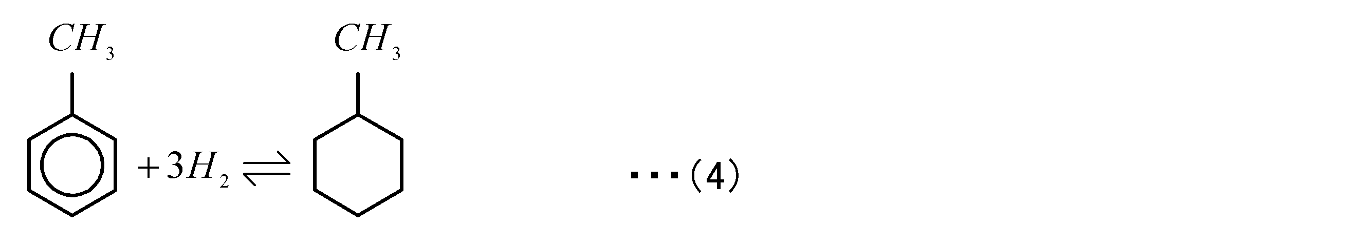

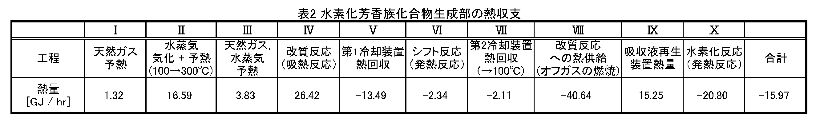
図2は本発明の第2実施形態に係る水素供給システムの概略構成を示すブロック図である。図2では、第1実施形態と同様の構成要素については同一の符号を付してある。また、図2では、第1実施形態における各構成要素のうち第2実施形態の説明において特に必要とされる構成要素以外のものは図示を省略してあるが、それら図示を省略した構成要素についても第2実施形態において採用可能である。第2実施形態については、以下で特に言及する事項を除いて、第1実施形態の場合と同様とする。

図3は本発明の第3実施形態に係る水素供給システムの概略構成を示すブロック図である。図3では、上述の第2実施形態と同様の構成要素については同一の符号を付してある。また、第3実施形態については、以下で特に言及する事項を除いて、第2実施形態と同様とする。
図4は本発明の第4実施形態に係る水素供給システムの概略構成を示すブロック図である。図4では、上述の第2または第3実施形態と同様の構成要素については同一の符号を付してある。また、第4実施形態については、以下で特に言及する事項を除いて、第2または第3実施形態と同様とする。
2 水素化芳香族化合物生成部
3 水素供給部
5 水蒸気改質装置
6 WGS装置(シフト反応装置)
7 二酸化炭素分離装置
8 水素精製装置
9 水素化装置
11 第1芳香族化合物タンク
12 第1水素化芳香族化合物タンク
15 第2芳香族化合物タンク
16 第2水素化芳香族化合物タンク
17 脱水素装置
21 第1加熱器
22 脱硫装置
24 STM製造装置
25 第2加熱器
26 第3加熱器
28 加熱炉
31 第1冷却装置
32 第2冷却装置
34 気液分離装置
36 第1二酸化炭素回収装置(第1吸収装置)
37 吸収液再生装置
38 第2二酸化炭素回収装置(第2吸収装置)
102 油田
103 油井(生産井)
111 石油分離装置
112 二酸化炭素分離装置
114 改質装置
121 第1圧入装置
122 二酸化炭素圧入井
140 シェール層
141 第2圧入装置
142 二酸化炭素圧入井
143 採ガス井(生産井)
145 二酸化炭素分離装置
Claims (12)
- 炭化水素の水蒸気改質を行う改質装置と、
前記改質装置から得られるガスの水性ガスシフト反応を行い、水素及び二酸化炭素を含むガスを得るシフト反応装置と、
前記シフト反応装置から得られるガスに含まれる二酸化炭素を吸収液に吸収させる第1吸収装置と、
前記第1吸収装置を通過したガスを用いて芳香族化合物の水素化反応を行い、水素化芳香族化合物を生成する水素化反応装置と、
前記第1吸収装置との間で吸収液の循環を行い、前記水素化反応によって発生する熱を利用して、二酸化炭素を吸収した吸収液を加熱し、吸収液から二酸化炭素を分離させる再生装置とを有することを特徴とする水素供給システム。 - 前記改質装置に熱を供給する加熱炉と、
前記加熱炉で発生した二酸化炭素を吸収液に吸収させる第2吸収装置とを更に有し、
前記第2吸収装置は前記再生装置との間で吸収液の循環を行い、前記第2吸収装置において二酸化炭素を吸収した吸収液は前記再生装置において加熱され、二酸化炭素が分離されることを特徴とする請求項1に記載の水素供給システム。 - 前記第1吸収装置を通過したガスから水素を分離し、分離した水素を前記水素化反応装置に供給する水素分離装置を有し、
前記加熱炉は、前記水素分離装置によって水素が分離された残りのガスの燃焼熱を前記水蒸気改質に供給することを特徴とする請求項2に記載の水素供給システム。 - 前記水素化反応によって発生する熱は、温度100℃~200℃、圧力0.10~1.62MPaAの水蒸気として前記再生装置に供給されることを特徴とする請求項1~請求項3のいずれか1つの項に記載の水素供給システム。
- 地中に埋蔵された化石燃料を採収するために当該化石燃料の流動性を向上させるべく、前記再生装置によって前記吸収液から分離された前記二酸化炭素を圧入井に圧入する圧入装置を更に備え、
前記改質装置は、前記化石燃料を採収するための生産井から、前記化石燃料に随伴して発生するまたは前記化石燃料として発生する産出ガスの少なくとも一部を改質することを特徴とする請求項1~請求項4のいずれかに記載の水素供給システム。 - 前記シフト反応装置から得られるガス中の前記水素および前記二酸化炭素を無機膜により相互に分離する第1分離装置を更に備えたことを特徴とする請求項5に記載の水素供給システム。
- 前記生産井は石油を埋蔵する油田に設けられ、前記石油を前記化石燃料として採収することを特徴とする請求項5または請求項6に記載の水素供給システム。
- 前記生産井は天然ガスを埋蔵するシェール層に設けられ、前記天然ガスを前記化石燃料として採収することを特徴とする請求項5または請求項6に記載の水素供給システム。
- 前記改質装置による前記産出ガスの改質前に、前記産出ガス中の硫黄成分を除去する脱硫設備を更に備えたことを特徴とする請求項5または請求項6に記載の水素供給システム。
- 前記シェール層から発生する前記天然ガスおよび前記圧入された前記二酸化炭素を含む産出ガスについて、これら天然ガスおよび二酸化炭素を相互に分離する第2分離装置を更に備え、
前記改質装置は、前記第2分離装置によって分離された前記天然ガスの少なくとも一部を改質し、
前記圧入装置は、地中における前記化石燃料の流動性を向上させるべく、前記第2分離装置によって分離された前記二酸化炭素を圧入井に圧入することを特徴とする請求項8に記載の水素供給システム。 - 炭化水素の水蒸気改質及び前記水蒸気改質によって生成されたガスの水性ガスシフト反応によって、水素及び二酸化炭素を含むガスを生成する水素生成工程と、
前記水素生成工程によって得られたガスに含まれる二酸化炭素を吸収液に吸収させる吸収工程と、
前記吸収工程を経たガスを用いて芳香族化合物の水素化反応を行い、水素化芳香族化合物を生成する水素化工程と、
前記水素化反応によって発生する熱を利用して、二酸化炭素を吸収した吸収液を加熱し、吸収液から二酸化炭素を分離させる再生工程とを有することを特徴とする水素供給方法。 - 地中に埋蔵された化石燃料を採収するために当該化石燃料の流動性を向上させるべく、前記再生工程において分離された前記二酸化炭素を圧入井に圧入する圧入工程を更に有し、
前記水素生成工程では、前記化石燃料を採収するための生産井から、前記化石燃料に随伴して発生するまたは前記化石燃料として発生する産出ガスの少なくとも一部が改質されることを特徴とする請求項11に記載の水素供給システム。
Priority Applications (6)
| Application Number | Priority Date | Filing Date | Title |
|---|---|---|---|
| AU2014303935A AU2014303935B2 (en) | 2013-08-06 | 2014-08-05 | Hydrogen supply system and hydrogen supply method |
| CA2920460A CA2920460C (en) | 2013-08-06 | 2014-08-05 | Hydrogen supply system and hydrogen supply method |
| RU2016107719A RU2667550C2 (ru) | 2013-08-06 | 2014-08-05 | Система подачи водорода и способ подачи водорода |
| EP14834642.2A EP3032027B1 (en) | 2013-08-06 | 2014-08-05 | Hydrogen supply system and hydrogen supply method |
| US14/910,161 US10131593B2 (en) | 2013-08-06 | 2014-08-05 | Systems and methods for producing hydrogen from a hydrocarbon and using the produced hydrogen in a hydrogenation reaction |
| SA516370530A SA516370530B1 (ar) | 2013-08-06 | 2016-02-03 | نظام وطريقة للإمداد بالهيدروجين |
Applications Claiming Priority (4)
| Application Number | Priority Date | Filing Date | Title |
|---|---|---|---|
| JP2013-163462 | 2013-08-06 | ||
| JP2013-163460 | 2013-08-06 | ||
| JP2013163462A JP2015031123A (ja) | 2013-08-06 | 2013-08-06 | 化石燃料採収システムおよび化石燃料採収方法 |
| JP2013163460A JP6153810B2 (ja) | 2013-08-06 | 2013-08-06 | 水素供給システム |
Publications (1)
| Publication Number | Publication Date |
|---|---|
| WO2015019608A1 true WO2015019608A1 (ja) | 2015-02-12 |
Family
ID=52460963
Family Applications (1)
| Application Number | Title | Priority Date | Filing Date |
|---|---|---|---|
| PCT/JP2014/004094 WO2015019608A1 (ja) | 2013-08-06 | 2014-08-05 | 水素供給システム及び水素供給方法 |
Country Status (7)
| Country | Link |
|---|---|
| US (1) | US10131593B2 (ja) |
| EP (1) | EP3032027B1 (ja) |
| AU (1) | AU2014303935B2 (ja) |
| CA (1) | CA2920460C (ja) |
| RU (1) | RU2667550C2 (ja) |
| SA (1) | SA516370530B1 (ja) |
| WO (1) | WO2015019608A1 (ja) |
Cited By (1)
| Publication number | Priority date | Publication date | Assignee | Title |
|---|---|---|---|---|
| US9776862B2 (en) * | 2015-02-26 | 2017-10-03 | Kobe Steel, Ltd. | Hydrogen production apparatus and hydrogen production method |
Families Citing this family (9)
| Publication number | Priority date | Publication date | Assignee | Title |
|---|---|---|---|---|
| FR3053034A1 (fr) * | 2016-06-22 | 2017-12-29 | Gauchi Georges Martino | Procede de fabrication d'hydrogene de schiste |
| MY190154A (en) * | 2016-08-23 | 2022-03-31 | Japan Blue Energy Co Ltd | Method for recovering hydrogen from biomass pyrolysis gas |
| CN110121586B (zh) | 2016-11-09 | 2022-01-25 | 八河流资产有限责任公司 | 用于电力生产和集成的氢气生产的系统和方法 |
| US9782718B1 (en) * | 2016-11-16 | 2017-10-10 | Membrane Technology And Research, Inc. | Integrated gas separation-turbine CO2 capture processes |
| PE20200682A1 (es) * | 2017-06-15 | 2020-06-11 | Reventech Inc | Proceso para producir hidrogeno a partir de yacimientos geotermicos subterraneos |
| CN108952659B (zh) * | 2018-07-11 | 2020-06-05 | 中国石油大学(北京) | 可视化超临界二氧化碳压裂物理模拟试验方法 |
| WO2020250194A1 (en) | 2019-06-13 | 2020-12-17 | 8 Rivers Capital, Llc | Power production with cogeneration of further products |
| RU2768354C1 (ru) * | 2021-09-28 | 2022-03-23 | Игорь Анатольевич Мнушкин | Комплекс по производству, хранению и транспортировке водорода |
| WO2023089570A1 (en) | 2021-11-18 | 2023-05-25 | 8 Rivers Capital, Llc | Apparatus for hydrogen production |
Citations (10)
| Publication number | Priority date | Publication date | Assignee | Title |
|---|---|---|---|---|
| JPH05301023A (ja) | 1992-02-27 | 1993-11-16 | Kansai Electric Power Co Inc:The | 燃焼排ガス中の二酸化炭素の除去方法 |
| WO2001004046A1 (fr) * | 1999-07-13 | 2001-01-18 | Ebara Corporation | Procede de production d'energie electrique a l'aide d'une pile a combustible et systeme de production d'energie electrique utilisant une pile a combustible |
| JP2003040601A (ja) * | 2001-07-27 | 2003-02-13 | Kansai Electric Power Co Inc:The | 水素供給方法 |
| JP2007031255A (ja) * | 2005-07-29 | 2007-02-08 | Toshiba Corp | 低質廃熱回収システム |
| JP2007153726A (ja) * | 2005-11-09 | 2007-06-21 | Epsilon Co Ltd | 混合ガスからの水素ガス回収方法及び水素ガス回収装置 |
| JP2008290927A (ja) * | 2007-05-24 | 2008-12-04 | Epsilon Co Ltd | 有機ハイドライドを用いる水素精製法およびその装置 |
| JP2009221057A (ja) * | 2008-03-17 | 2009-10-01 | Japan Energy Corp | 水素製造システム |
| JP2012519649A (ja) * | 2009-03-09 | 2012-08-30 | ビーピー オルタネイティブ エナジー インターナショナル リミテッド | 二酸化炭素及び水素の分離 |
| JP2012176879A (ja) * | 2011-01-31 | 2012-09-13 | Osaka Gas Co Ltd | 水素製造装置 |
| JP2013049601A (ja) | 2011-08-31 | 2013-03-14 | Hitachi Ltd | エネルギー供給システム |
Family Cites Families (18)
| Publication number | Priority date | Publication date | Assignee | Title |
|---|---|---|---|---|
| US3694344A (en) * | 1970-09-24 | 1972-09-26 | William H Munro | Hydroprocessing of hydrocarbons |
| US4052176A (en) * | 1975-09-29 | 1977-10-04 | Texaco Inc. | Production of purified synthesis gas H2 -rich gas, and by-product CO2 -rich gas |
| CA2498195C (en) | 2002-09-17 | 2010-01-26 | Fluor Corporation | Configurations and methods of acid gas removal |
| US7029517B2 (en) * | 2003-11-06 | 2006-04-18 | General Electric Company | Devices and methods for hydrogen storage and generation |
| JP2005200254A (ja) | 2004-01-14 | 2005-07-28 | Jfe Engineering Kk | 水素ガスを含む混合ガスからの水素の選択的回収方法 |
| KR100803074B1 (ko) * | 2007-03-20 | 2008-02-18 | 박정태 | 수소발생용 조성물 및 이를 이용한 고순도 수소발생 장치 |
| US8076121B2 (en) * | 2007-07-25 | 2011-12-13 | Chevron U.S.A. Inc. | Integrated process for conversion of hydrocarbonaceous assets and photobiofuels production |
| JP5039472B2 (ja) | 2007-07-27 | 2012-10-03 | Jx日鉱日石エネルギー株式会社 | 水素製造および二酸化炭素回収方法ならびに装置 |
| RU2373454C1 (ru) * | 2008-03-12 | 2009-11-20 | Игорь Витальевич Горячев | Система хранения и подачи водорода |
| JP5424569B2 (ja) * | 2008-03-31 | 2014-02-26 | 独立行政法人石油天然ガス・金属鉱物資源機構 | 天然ガスからの液状炭化水素製造プロセスにおける合成ガスの製造方法 |
| FR2939693B1 (fr) * | 2008-12-16 | 2011-12-23 | Inst Francais Du Petrole | Nouveau procede de recuperation du co2 issu des fumees de regeneration d'une unite de craquage catalytique |
| US8007761B2 (en) * | 2008-12-24 | 2011-08-30 | Praxair Technology, Inc. | Carbon dioxide emission reduction method |
| JP5301330B2 (ja) * | 2009-03-27 | 2013-09-25 | 独立行政法人石油天然ガス・金属鉱物資源機構 | 液体炭化水素の合成方法及び液体炭化水素の合成システム |
| MY160346A (en) * | 2010-03-02 | 2017-02-28 | Japan Oil Gas & Metals Jogmec | Method for removing sulfur compounds in castable |
| JP5638600B2 (ja) * | 2010-03-02 | 2014-12-10 | 独立行政法人石油天然ガス・金属鉱物資源機構 | 合成ガスの製造方法 |
| US8858679B2 (en) * | 2010-06-01 | 2014-10-14 | Shell Oil Company | Separation of industrial gases |
| GB201115929D0 (en) * | 2011-09-15 | 2011-10-26 | Johnson Matthey Plc | Improved hydrocarbon production process |
| JP2013087021A (ja) | 2011-10-19 | 2013-05-13 | Hitachi Ltd | 化石燃料から合成ガスを生成するプラントの二酸化炭素回収システム |
-
2014
- 2014-08-05 US US14/910,161 patent/US10131593B2/en active Active
- 2014-08-05 WO PCT/JP2014/004094 patent/WO2015019608A1/ja active Application Filing
- 2014-08-05 CA CA2920460A patent/CA2920460C/en active Active
- 2014-08-05 AU AU2014303935A patent/AU2014303935B2/en active Active
- 2014-08-05 RU RU2016107719A patent/RU2667550C2/ru active
- 2014-08-05 EP EP14834642.2A patent/EP3032027B1/en active Active
-
2016
- 2016-02-03 SA SA516370530A patent/SA516370530B1/ar unknown
Patent Citations (10)
| Publication number | Priority date | Publication date | Assignee | Title |
|---|---|---|---|---|
| JPH05301023A (ja) | 1992-02-27 | 1993-11-16 | Kansai Electric Power Co Inc:The | 燃焼排ガス中の二酸化炭素の除去方法 |
| WO2001004046A1 (fr) * | 1999-07-13 | 2001-01-18 | Ebara Corporation | Procede de production d'energie electrique a l'aide d'une pile a combustible et systeme de production d'energie electrique utilisant une pile a combustible |
| JP2003040601A (ja) * | 2001-07-27 | 2003-02-13 | Kansai Electric Power Co Inc:The | 水素供給方法 |
| JP2007031255A (ja) * | 2005-07-29 | 2007-02-08 | Toshiba Corp | 低質廃熱回収システム |
| JP2007153726A (ja) * | 2005-11-09 | 2007-06-21 | Epsilon Co Ltd | 混合ガスからの水素ガス回収方法及び水素ガス回収装置 |
| JP2008290927A (ja) * | 2007-05-24 | 2008-12-04 | Epsilon Co Ltd | 有機ハイドライドを用いる水素精製法およびその装置 |
| JP2009221057A (ja) * | 2008-03-17 | 2009-10-01 | Japan Energy Corp | 水素製造システム |
| JP2012519649A (ja) * | 2009-03-09 | 2012-08-30 | ビーピー オルタネイティブ エナジー インターナショナル リミテッド | 二酸化炭素及び水素の分離 |
| JP2012176879A (ja) * | 2011-01-31 | 2012-09-13 | Osaka Gas Co Ltd | 水素製造装置 |
| JP2013049601A (ja) | 2011-08-31 | 2013-03-14 | Hitachi Ltd | エネルギー供給システム |
Non-Patent Citations (5)
| Title |
|---|
| See also references of EP3032027A4 |
| YOSHIMI OKADA ET AL.: "Dehydrogenation Catalyst Development for Organic Chemical Hydride Method and Hydrogen Energy Chain Vision", CATALYST, vol. 51, no. 6, 2009, pages 496 - 498 |
| YOSHIMI OKADA ET AL.: "Development of Dehydrogenation Catalyst for Organic Chemical Hydride Method for Storage and Transportation of Hydrogen", FINE CHEMICAL, vol. 35, no. 1, 2006, pages 5 - 13 |
| YOSHIMI OKADA ET AL.: "Development of Dehydrogenation Catalyst for Organic Chemical Hydride Method with a View of Establishing Large-Volume, Long-Distance Storage and Transportation Technology for Hydrogen Energy", CHEMICAL ENGINEERING, vol. 74, no. 9, 2010, pages 468 - 470 |
| YOSHIMI OKADA ET AL.: "Development of Dehydrogenation Catalyst for Organic Chemical Hydride Method", CATALYST, vol. 46, no. 6, 2004, pages 510 - 512 |
Cited By (1)
| Publication number | Priority date | Publication date | Assignee | Title |
|---|---|---|---|---|
| US9776862B2 (en) * | 2015-02-26 | 2017-10-03 | Kobe Steel, Ltd. | Hydrogen production apparatus and hydrogen production method |
Also Published As
| Publication number | Publication date |
|---|---|
| RU2016107719A3 (ja) | 2018-04-26 |
| SA516370530B1 (ar) | 2020-09-21 |
| EP3032027A1 (en) | 2016-06-15 |
| EP3032027A4 (en) | 2017-12-27 |
| AU2014303935B2 (en) | 2018-05-24 |
| CA2920460C (en) | 2020-03-10 |
| CA2920460A1 (en) | 2015-02-12 |
| US20160176784A1 (en) | 2016-06-23 |
| RU2016107719A (ru) | 2017-09-14 |
| EP3032027B1 (en) | 2019-10-09 |
| US10131593B2 (en) | 2018-11-20 |
| AU2014303935A1 (en) | 2016-03-10 |
| RU2667550C2 (ru) | 2018-09-21 |
Similar Documents
| Publication | Publication Date | Title |
|---|---|---|
| WO2015019608A1 (ja) | 水素供給システム及び水素供給方法 | |
| Muradov | Low to near-zero CO2 production of hydrogen from fossil fuels: Status and perspectives | |
| JP5280343B2 (ja) | 二酸化炭素分離回収装置を伴う水素分離型水素製造システム | |
| KR101850268B1 (ko) | 수소 및 합성 천연가스의 제조 장치 및 제조 방법 | |
| CN101905866A (zh) | 同时固定co2的柴油蒸汽重整 | |
| JP6194143B2 (ja) | 水素及び合成天然ガスの製造装置及び製造方法 | |
| JP2010229360A (ja) | 液体炭化水素の合成方法及び液体炭化水素の合成システム | |
| AU2022221398B2 (en) | Hydrogen generation assemblies | |
| JP2009221057A (ja) | 水素製造システム | |
| JP6126952B2 (ja) | エネルギー供給システム及びエネルギー供給方法 | |
| JP2007153726A (ja) | 混合ガスからの水素ガス回収方法及び水素ガス回収装置 | |
| JP5039471B2 (ja) | 水素製造および二酸化炭素回収方法ならびに装置 | |
| JP5348938B2 (ja) | 一酸化炭素ガス発生装置および方法 | |
| JP5039470B2 (ja) | 水素製造および二酸化炭素回収方法ならびに装置 | |
| JP4135871B2 (ja) | 排熱を熱源として灯油または軽油を改質する装置及び方法 | |
| JP6153810B2 (ja) | 水素供給システム | |
| JP2008207969A (ja) | 水素製造装置、水素製造システムおよび水素製造方法 | |
| WO2023026765A1 (ja) | 炭化水素製造システム | |
| JP2015031123A (ja) | 化石燃料採収システムおよび化石燃料採収方法 | |
| JP5285952B2 (ja) | 一酸化炭素ガス発生装置および方法 | |
| EA021005B1 (ru) | Система отделения катализатора | |
| JP2002274809A (ja) | 化学反応装置 | |
| Basile et al. | Membrane Processes for Pure Hydrogen Production from Biomass | |
| JP2016013937A (ja) | 水素供給体の製造方法 | |
| JP2008163103A (ja) | 浮選濾過ケーキの改質システム |
Legal Events
| Date | Code | Title | Description |
|---|---|---|---|
| 121 | Ep: the epo has been informed by wipo that ep was designated in this application |
Ref document number: 14834642 Country of ref document: EP Kind code of ref document: A1 |
|
| WWE | Wipo information: entry into national phase |
Ref document number: 139450140003012700 Country of ref document: IR |
|
| ENP | Entry into the national phase |
Ref document number: 2920460 Country of ref document: CA |
|
| WWE | Wipo information: entry into national phase |
Ref document number: 14910161 Country of ref document: US |
|
| WWE | Wipo information: entry into national phase |
Ref document number: P142/2016 Country of ref document: AE |
|
| NENP | Non-entry into the national phase |
Ref country code: DE |
|
| WWE | Wipo information: entry into national phase |
Ref document number: 2014834642 Country of ref document: EP |
|
| ENP | Entry into the national phase |
Ref document number: 2016107719 Country of ref document: RU Kind code of ref document: A |
|
| ENP | Entry into the national phase |
Ref document number: 2014303935 Country of ref document: AU Date of ref document: 20140805 Kind code of ref document: A |