WO2015019545A1 - 通気部材 - Google Patents
通気部材 Download PDFInfo
- Publication number
- WO2015019545A1 WO2015019545A1 PCT/JP2014/003622 JP2014003622W WO2015019545A1 WO 2015019545 A1 WO2015019545 A1 WO 2015019545A1 JP 2014003622 W JP2014003622 W JP 2014003622W WO 2015019545 A1 WO2015019545 A1 WO 2015019545A1
- Authority
- WO
- WIPO (PCT)
- Prior art keywords
- ventilation member
- wall portion
- peripheral surface
- member according
- ventilation
- Prior art date
Links
Images


Classifications
-
- B—PERFORMING OPERATIONS; TRANSPORTING
- B01—PHYSICAL OR CHEMICAL PROCESSES OR APPARATUS IN GENERAL
- B01D—SEPARATION
- B01D39/00—Filtering material for liquid or gaseous fluids
- B01D39/14—Other self-supporting filtering material ; Other filtering material
- B01D39/16—Other self-supporting filtering material ; Other filtering material of organic material, e.g. synthetic fibres
- B01D39/1638—Other self-supporting filtering material ; Other filtering material of organic material, e.g. synthetic fibres the material being particulate
- B01D39/1653—Other self-supporting filtering material ; Other filtering material of organic material, e.g. synthetic fibres the material being particulate of synthetic origin
- B01D39/1661—Other self-supporting filtering material ; Other filtering material of organic material, e.g. synthetic fibres the material being particulate of synthetic origin sintered or bonded
-
- B—PERFORMING OPERATIONS; TRANSPORTING
- B01—PHYSICAL OR CHEMICAL PROCESSES OR APPARATUS IN GENERAL
- B01D—SEPARATION
- B01D46/00—Filters or filtering processes specially modified for separating dispersed particles from gases or vapours
- B01D46/10—Particle separators, e.g. dust precipitators, using filter plates, sheets or pads having plane surfaces
-
- B—PERFORMING OPERATIONS; TRANSPORTING
- B01—PHYSICAL OR CHEMICAL PROCESSES OR APPARATUS IN GENERAL
- B01D—SEPARATION
- B01D46/00—Filters or filtering processes specially modified for separating dispersed particles from gases or vapours
- B01D46/24—Particle separators, e.g. dust precipitators, using rigid hollow filter bodies
- B01D46/2403—Particle separators, e.g. dust precipitators, using rigid hollow filter bodies characterised by the physical shape or structure of the filtering element
-
- B—PERFORMING OPERATIONS; TRANSPORTING
- B01—PHYSICAL OR CHEMICAL PROCESSES OR APPARATUS IN GENERAL
- B01D—SEPARATION
- B01D46/00—Filters or filtering processes specially modified for separating dispersed particles from gases or vapours
- B01D46/52—Particle separators, e.g. dust precipitators, using filters embodying folded corrugated or wound sheet material
- B01D46/521—Particle separators, e.g. dust precipitators, using filters embodying folded corrugated or wound sheet material using folded, pleated material
-
- F—MECHANICAL ENGINEERING; LIGHTING; HEATING; WEAPONS; BLASTING
- F21—LIGHTING
- F21S—NON-PORTABLE LIGHTING DEVICES; SYSTEMS THEREOF; VEHICLE LIGHTING DEVICES SPECIALLY ADAPTED FOR VEHICLE EXTERIORS
- F21S45/00—Arrangements within vehicle lighting devices specially adapted for vehicle exteriors, for purposes other than emission or distribution of light
- F21S45/30—Ventilation or drainage of lighting devices
-
- H—ELECTRICITY
- H05—ELECTRIC TECHNIQUES NOT OTHERWISE PROVIDED FOR
- H05K—PRINTED CIRCUITS; CASINGS OR CONSTRUCTIONAL DETAILS OF ELECTRIC APPARATUS; MANUFACTURE OF ASSEMBLAGES OF ELECTRICAL COMPONENTS
- H05K5/00—Casings, cabinets or drawers for electric apparatus
- H05K5/02—Details
- H05K5/0213—Venting apertures; Constructional details thereof
- H05K5/0215—Venting apertures; Constructional details thereof with semi-permeable membranes attached to casings
-
- B—PERFORMING OPERATIONS; TRANSPORTING
- B01—PHYSICAL OR CHEMICAL PROCESSES OR APPARATUS IN GENERAL
- B01D—SEPARATION
- B01D2279/00—Filters adapted for separating dispersed particles from gases or vapours specially modified for specific uses
- B01D2279/35—Filters adapted for separating dispersed particles from gases or vapours specially modified for specific uses for venting arrangements
-
- B—PERFORMING OPERATIONS; TRANSPORTING
- B01—PHYSICAL OR CHEMICAL PROCESSES OR APPARATUS IN GENERAL
- B01D—SEPARATION
- B01D2279/00—Filters adapted for separating dispersed particles from gases or vapours specially modified for specific uses
- B01D2279/45—Filters adapted for separating dispersed particles from gases or vapours specially modified for specific uses for electronic devices, e.g. computers, hard-discs, mobile phones
Definitions
- the present invention relates to a ventilation member that is used to relieve pressure fluctuations in the housing or to ventilate the inside of the housing.
- automotive electrical components such as automotive lamps and ECUs (Electrical Control Units), OA (office automation) devices, home appliances, medical devices, etc.
- An opening is provided for the purpose of alleviating pressure fluctuations in the casing or ventilating the casing, and a ventilation member is attached to the opening.
- This ventilation member prevents intrusion of foreign matters such as dust and water into the casing while ensuring ventilation inside and outside the casing.
- An example of such a ventilation member is disclosed in Patent Document 1.
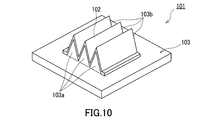
- Patent Document 1 discloses a ventilation member 101 as shown in FIGS.
- the ventilation member 101 includes a gas permeable membrane 102 and a support body 103.
- the support 103 is provided along the through-hole 103c and both edges of the opening of the through-hole 103c, and includes a first chevron protrusion 103a and a second chevron protrusion 103b in which peaks and valleys are alternately arranged.
- the gas permeable membrane 102 is joined on the first and second chevron protrusions 103a and 103b, and the ridges and the valleys are alternately arranged along the shapes of the first and second chevron protrusions 103a and 103b. It has a pleated shape lined up.
- Patent Document 1 discloses a polytetrafluoroethylene (PTFE) porous membrane as the gas permeable membrane 102.
- the gas permeable membrane 102 made of a PTFE porous membrane is made porous by stretching and then given the shape shown in the figure by pleating.
- the ventilation area is increased by pleating the ventilation film 102.
- the first chevron protrusion 103a and the second chevron protrusion 103b formed by the support 103 having no air permeability do not contribute to the improvement of air permeability.
- the pleat shape of the gas permeable membrane 102 and the shapes of the projections 103a and 103b are used. High accuracy is required for the joining work. For this reason, the ventilation member 101 is not necessarily designed for mass production.
- an object of the present invention is to provide a ventilation member suitable for improvement in air permeability and mass production.
- the present invention Formed of a porous resin and having a recess having at least one opening; A wall portion that is formed so as to surround the concave portion and is capable of venting between an inner peripheral surface facing the concave portion and an outer peripheral surface opposite to the inner peripheral surface; Provided is a ventilation member including an attachment portion that is formed integrally with the wall portion so as to extend in the circumferential direction around the opening of the concave portion, and is attached to a housing that requires ventilation.
- air permeability is ensured by the entire wall portion formed so as to surround the recess. Moreover, the attachment part for mounting
- FIG. 1 It is a perspective view of the ventilation member concerning a 1st embodiment of the present invention. It is sectional drawing of the ventilation member shown in FIG. It is a perspective view when the ventilation member shown in FIG. 1 is seen from the back side. It is a perspective view of the ventilation member concerning a 2nd embodiment of the present invention. It is sectional drawing of the ventilation member shown in FIG. It is a perspective view when the ventilation member shown in FIG. 4 is seen from the back side. It is a perspective view of the ventilation member concerning a 3rd embodiment of the present invention. It is sectional drawing of the ventilation member shown in FIG. It is a perspective view when the ventilation member shown in FIG. 7 is seen from the back side. It is a perspective view of the conventional ventilation member. It is a side view of the ventilation member shown in FIG. It is sectional drawing of the ventilation member shown in FIG.
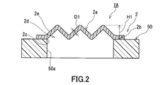
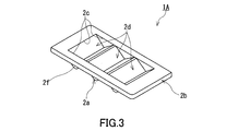
- the ventilation member 1A includes a wall portion 2a and a mounting portion 2b, and has a plurality of (specifically, three) concave portions 2d. These recesses 2d have one common opening 2c and recede in the same direction from this opening 2c.
- the wall 2a is formed so as to surround each recess 2d, and allows air to pass between the inner peripheral surface facing each recess 2d and the outer peripheral surface opposite to the inner peripheral surface.
- the mounting portion 2b is formed so as to extend in the circumferential direction around the rectangular opening 2c, and provides a mounting surface for mounting on the casing 50 that requires ventilation.
- the ventilation member 1A is formed of a porous resin, and at least the wall portion 2a and the attachment portion 2b are integrally formed. Each of the wall portion 2a and the attachment portion 2b is a portion of the ventilation member 1A that is one member formed of a porous resin, and is not a member that is individually molded and joined.
- the wall portion 2a has an inclined portion 2e whose cross-sectional shape is formed in a mountain shape, and a mountain-shaped portion 2f that closes both side portions of the inclined portion 2e.
- the inclined portion 2e has a pleated shape in which the top portion is a flat peak portion, and is configured by three convex portions.
- the chevron part 2f covers both sides of each of the convex parts and is composed of six convex parts.
- the shape (for example, the slope of a convex part or the inclination angle of a hypotenuse) and number of the inclination part 2e and the mountain-shaped part 2f are not specifically limited.
- the inclined part 2e and the chevron part 2f are integrally formed of a porous resin and constitute a wall part 2a.
- the mounting portion 2b is usually fixed to the outer peripheral surface of the casing 50 by a fixing means such as an adhesive tape or an adhesive.
- the attaching part 2b may be directly fixed to the outer peripheral surface of the normal casing 50 by welding or the like.
- the opening 50a of the housing 50 is formed in a rectangular shape, and the opening 2c is also formed in the same rectangle as the opening 50a so as to match this.
- the opening 2 c is disposed at a position communicating with the opening 50 a of the housing 50. Since the attachment portion 2b is formed of a porous resin like the wall portion 2a, the inside thereof can function as a ventilation path. However, since the inner peripheral surface of the mounting portion 2b is fixed to the wall material of the casing 50 that does not have air permeability, the air permeability of the ventilation member 1A is substantially ensured by the wall portion 2a.
- the porous resin forming the ventilation member 1A is a porous molded body formed by binding resin fine particles to each other.
- the porosity of the porous resin molded body is preferably 20 to 90%.
- Ultra high molecular weight polyethylene is preferable.
- “ultra high molecular weight polyethylene” refers to polyethylene having an average molecular weight of 500,000 or more.
- the average molecular weight of ultra high molecular weight polyethylene is usually in the range of 2 to 10 million.
- An average molecular weight can be measured by the method prescribed
- ultra high molecular weight polyethylene is abbreviated as “UHMWPE (Ultra High High Molecular Weight Polyethylene)”.
- the UHMWPE porous resin molding can be manufactured from a sintered body of UHMWPE powder.
- the sintered body of UHMWPE powder is obtained by sintering UHMWPE powder (for example, average particle size of 30 to 200 ⁇ m) filled in a mold at a temperature near the melting point of UHMWPE (for example, 130 to 160 ° C.).
- the porosity of the obtained UHMWPE porous resin molding is in the range of 20 to 90%.
- the surface of the ventilation member 1A may be subjected to a liquid repellent treatment.
- the liquid repellent treatment can be performed by a known method.
- the liquid repellent used for the liquid repellent treatment is not particularly limited, and is typically a material containing a polymer having a perfluoroalkyl group.
- the method of forming a film containing a polymer having a perfluoroalkyl group includes air spray method, electrostatic spray method, dip coating method, spin coating method, roll coating method (including kiss coating method and gravure coating method), curtain flow.
- Examples thereof include coating of a polymer solution or dispersion having a perfluoroalkyl group by a coating method, an impregnation method or the like, a film forming method by an electrodeposition coating method or a plasma polymerization method, and the like.
- a polymer having a general formula C 4 F 9 (CH 2 CF 2 ) (CF 2 CF 2 ) 2 CH 2 CH 2 OCOCH ⁇ CH 2 as a monomer component is used as a constituent component.
- Solution can be used.
- the thickness D1 (thickness of the wall portion 2a) of the ventilation member 1A is preferably 0.2 mm or more and 20 mm or less, and preferably 0.3 mm or more and 10 mm or less from the viewpoint of achieving both strength and air permeability of the member. It is preferably 0.5 mm or more and 10 mm or less, more preferably 1 mm or more and 5 mm or less, and particularly preferably 1.5 mm or more and 5 mm or less.
- the thickness of the attachment portion 2b may be the same as the thickness of the wall portion 2a or may be designed to be slightly thick.
- the height H1 (height measured from the outer peripheral surface of the housing 50) of the ventilation member 1A is preferably 5 mm or more and 50 mm or less, and preferably 10 mm or more and 30 mm or less.
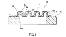
- the ventilation member 1B includes a wall portion 3a and a mounting portion 3b, and has a plurality of (specifically, four) concave portions 3d.
- the wall 3a is formed so as to surround the recess 3d, and serves as a portion that can ventilate between the inner peripheral surface facing each recess 3d and the outer peripheral surface opposite to the inner peripheral surface. These recesses 3d have one common opening 3c, and recede in the same direction from this opening 3c.
- the mounting portion 3b is formed so as to extend in the circumferential direction around the rectangular opening 3c, and provides a mounting surface for mounting on the housing 50 that requires ventilation.
- the ventilation member 1B is formed of a porous resin, and at least the wall portion 3a and the attachment portion 3b are integrally formed. Each of the wall portion 3a and the attachment portion 3b is a portion of the ventilation member 1B that is one member formed of a porous resin, and is not a member that is individually molded and joined.
- the wall 3a has a bottom wall 3e that forms the bottom surface of the recess 3d and a side wall 3f that forms the side surface of the recess 3d.
- the wall part 3a is comprised by the four convex parts independent from each other, and each convex part has the bottom wall part 3e and the side wall part 3f.
- the four convex portions are connected to each other by the connecting portion 3g.
- the surface of the connecting portion 3g facing the outside of the housing 50 is smoothly connected to the surface of the mounting portion 3b.
- the shape and number of the bottom wall part 3e and the side wall part 3f are not specifically limited.
- the outer shape of the bottom wall 3e may be circular instead of rectangular, and the side wall 3f may be cylindrical.
- the bottom wall portion 3e, the side wall portion 3f, and the connecting portion 3g are integrally formed of a porous resin and constitute the wall portion 3a.
- the bottom wall portion 3e, the side wall portion 3f, and the connecting portion 3g can each be ventilated between the inner peripheral surface and the outer peripheral surface opposite to the inner peripheral surface.
- the attachment part 3b is the same as the attachment part 2b, description is abbreviate
- the attachment part 3b is formed around the area including all the recesses 3d. Is done.
- the porous resin forming the ventilation member 1B is a porous molded body formed by binding resin fine particles to each other. Although it does not specifically limit as resin, Ultra high molecular weight polyethylene is preferable. Further, the surface of the ventilation member 1B may be subjected to a liquid repellent treatment.
- the preferable range of the thickness D2 (the thickness of the bottom wall 3e) of the ventilation member 1B is the same as the preferable range of the thickness D1
- the preferable range of the height H2 of the ventilation member 1B is the height. It is the same as the preferable range of H1.
- the ventilation member 1C includes a wall portion 4a and a mounting portion 4b, and has a recess 4d having an opening 4c.
- the wall 4a is formed so as to surround the recess 4d, and allows air to pass between the inner peripheral surface facing the recess 4d and the outer peripheral surface opposite to the inner peripheral surface.
- the mounting portion 4b is formed so as to extend in the circumferential direction around the opening 4c, and provides a mounting surface for mounting on the casing 50 that requires ventilation.
- the number of the recesses 4d is one, but there are a plurality of recesses (projections when viewed from the opposite side), and the mounting portion 4b is formed around the region surrounding these recesses. Good.
- the ventilation member 1C is formed of a porous resin, and at least the wall portion 4a and the attachment portion 4b are integrally formed.
- the wall 4a has a bottom wall 4e that forms the bottom surface of the recess 4d and a side wall 4f that forms the side surface of the recess 4d.
- the side wall portion 4f has a pleated structure 4g in which ridges and valleys are alternately arranged. Due to the pleat structure 4g, the surface area of the side wall portion 4f is enlarged as compared with the configuration without the pleat structure 4g. In the illustrated form, the surface of the pleat structure 4g is a flat surface, but the surface may be a curved surface.
- attachment part 4b is the same as the attachment part 2b, description is abbreviate
- the porous resin forming the ventilation member 1C is a porous molded body formed by binding resin fine particles to each other. Although it does not specifically limit as resin, Ultra high molecular weight polyethylene is preferable. Further, the surface of the ventilation member 1C may be subjected to a liquid repellent treatment.
- the preferable range of the thickness D3 (the thickness of the bottom wall portion 4e) of the ventilation member 1C is the same as the preferable range of the thickness D1, and the height H3 of the ventilation member 1B (the outer peripheral surface of the casing 50). Is preferably from 5 mm to 50 mm, and more preferably from 10 mm to 30 mm.
- the waterproof ventilation member according to the present invention can be applied to other than the body of an automobile electrical component.
- the present invention can be applied to a housing of an OA device, a home appliance, or a medical device.
Landscapes
- Chemical & Material Sciences (AREA)
- Chemical Kinetics & Catalysis (AREA)
- Engineering & Computer Science (AREA)
- Microelectronics & Electronic Packaging (AREA)
- Physics & Mathematics (AREA)
- Geometry (AREA)
- General Engineering & Computer Science (AREA)
- Casings For Electric Apparatus (AREA)
- Arrangement Of Elements, Cooling, Sealing, Or The Like Of Lighting Devices (AREA)
- Non-Portable Lighting Devices Or Systems Thereof (AREA)
- Filtering Materials (AREA)
Abstract
Description
多孔質樹脂により形成され、少なくとも1つの開口を有する凹部を有し、
前記凹部を囲むように形成され、前記凹部に面する内周面と前記内周面の反対側の外周面との間が通気可能である壁部と、
前記凹部の開口の周囲に周方向に延びるように前記壁部と一体として形成され、通気を要する筐体に装着するための取付部と、を備えた、通気部材を提供する。
本発明の第1実施形態に係る通気部材1Aを図1~図3に示す。通気部材1Aは、壁部2aと取付部2bとを備え、複数の(具体的には3つの)凹部2dを有している。これらの凹部2dは、共通する1つの開口2cを有し、この開口2cから同一方向へと後退している。壁部2aは、各凹部2dを囲むように形成され、各凹部2dに面する内周面と内周面の反対側の外周面との間を通気可能としている。取付部2bは、矩形の開口2cの周囲に周方向に延びるように形成され、通気を要する筐体50に装着するための装着面を提供している。通気部材1Aは、多孔質樹脂により形成され、少なくとも壁部2aと取付部2bとが一体として形成されている。壁部2a及び取付部2bは、それぞれ、多孔質樹脂により形成された一部材である通気部材1Aの部分であり、個別に成形されて接合された部材ではない。
次に、図4~図6を参照して、本発明の第2実施形態に係る通気部材1Bを説明する。
次に、図7~図9を参照して、本発明の第3実施形態に係る通気部材1Cを説明する。
Claims (9)
- 多孔質樹脂により形成され、少なくとも1つの開口を有する凹部を有し、
前記凹部を囲むように形成され、前記凹部に面する内周面と前記内周面の反対側の外周面との間が通気可能である壁部と、
前記凹部の開口の周囲に周方向に延びるように前記壁部と一体として形成され、通気を要する筐体に装着するための取付部と、を備えた、通気部材。 - 前記壁部は、断面形状が山形に形成された傾斜部と、前記傾斜部の両側部を閉塞する山形部と、を有している、請求項1に記載の通気部材。
- 前記壁部は、前記凹部の側面を形成する側壁部と、前記凹部の底面を形成する底壁部と、を有している、請求項1に記載の通気部材。
- 前記側壁部は、当該側壁部の表面積を拡大するためのひだ構造を有している、請求項3に記載の通気部材。
- 複数の前記凹部を有している、請求項1に記載の通気部材。
- 表面が撥液処理されている、請求項1に記載の通気部材。
- 前記多孔質樹脂は、樹脂の微粒子が互いに結着して構成された多孔質成形体である、請求項1に記載の通気部材。
- 前記通気部材の厚みは、0.2mm以上20mm以下である、請求項1に記載の通気部材。
- 前記多孔質樹脂の気孔率は、20%以上90%以下である、請求項1に記載の通気部材。
Priority Applications (4)
| Application Number | Priority Date | Filing Date | Title |
|---|---|---|---|
| US14/903,518 US20160158678A1 (en) | 2013-08-09 | 2014-07-08 | Ventilation member |
| EP14835423.6A EP3032166A4 (en) | 2013-08-09 | 2014-07-08 | Ventilation member |
| CN201480043920.XA CN105452760A (zh) | 2013-08-09 | 2014-07-08 | 通气构件 |
| KR1020167002767A KR20160027148A (ko) | 2013-08-09 | 2014-07-08 | 통기 부재 |
Applications Claiming Priority (2)
| Application Number | Priority Date | Filing Date | Title |
|---|---|---|---|
| JP2013-167051 | 2013-08-09 | ||
| JP2013167051A JP2015035406A (ja) | 2013-08-09 | 2013-08-09 | 通気部材 |
Publications (1)
| Publication Number | Publication Date |
|---|---|
| WO2015019545A1 true WO2015019545A1 (ja) | 2015-02-12 |
Family
ID=52460908
Family Applications (1)
| Application Number | Title | Priority Date | Filing Date |
|---|---|---|---|
| PCT/JP2014/003622 WO2015019545A1 (ja) | 2013-08-09 | 2014-07-08 | 通気部材 |
Country Status (6)
| Country | Link |
|---|---|
| US (1) | US20160158678A1 (ja) |
| EP (1) | EP3032166A4 (ja) |
| JP (1) | JP2015035406A (ja) |
| KR (1) | KR20160027148A (ja) |
| CN (1) | CN105452760A (ja) |
| WO (1) | WO2015019545A1 (ja) |
Families Citing this family (2)
| Publication number | Priority date | Publication date | Assignee | Title |
|---|---|---|---|---|
| JP2018024292A (ja) * | 2016-08-08 | 2018-02-15 | 日東電工株式会社 | 通気部材 |
| CN113015358B (zh) * | 2019-12-19 | 2022-08-05 | 富联精密电子(天津)有限公司 | 外壳及具有所述外壳的户外设备 |
Citations (3)
| Publication number | Priority date | Publication date | Assignee | Title |
|---|---|---|---|---|
| WO2010053121A1 (ja) * | 2008-11-06 | 2010-05-14 | ジャパンゴアテックス株式会社 | 通気栓 |
| JP2011519136A (ja) * | 2008-04-24 | 2011-06-30 | ゴア エンタープライズ ホールディングス,インコーポレイティド | ランプ包囲体用換気システム |
| JP2011233518A (ja) | 2010-04-09 | 2011-11-17 | Nitto Denko Corp | 通気部材 |
Family Cites Families (9)
| Publication number | Priority date | Publication date | Assignee | Title |
|---|---|---|---|---|
| DE3311252A1 (de) * | 1983-03-28 | 1984-10-04 | Joachim Dr.-Ing. 8070 Ingolstadt Hess | Kunststoffgehaeuse |
| DE3413213A1 (de) * | 1984-04-07 | 1985-10-24 | Herding GmbH Entstaubungsanlagen, 8450 Amberg | Filterelement zum abscheiden von feststoffteilchen aus gasfoermigen oder fluessigen medien |
| US5674302A (en) * | 1994-07-12 | 1997-10-07 | Nippondenso Co., Ltd. | Automobile filter element |
| JP3301227B2 (ja) * | 1994-07-28 | 2002-07-15 | 株式会社デンソー | フィルタの製造方法 |
| JP3640729B2 (ja) * | 1996-04-02 | 2005-04-20 | 日東電工株式会社 | 簡易濾過フィルタ |
| JP3725614B2 (ja) * | 1996-05-29 | 2005-12-14 | 三菱樹脂株式会社 | 微粒子分離用多孔質プラスチックフィルタ |
| JP2010058026A (ja) * | 2008-09-02 | 2010-03-18 | Fujifilm Corp | 結晶性ポリマー微孔性膜及びその製造方法、並びに濾過用フィルタ |
| US9693843B2 (en) * | 2009-05-22 | 2017-07-04 | Howard Cohen | Strainer/filter unit for an aspirating filtration system and method thereof |
| EP2721103A1 (en) * | 2011-06-15 | 2014-04-23 | Porex Corporation | Sintered porous plastic liquid barrier media and applications thereof |
-
2013
- 2013-08-09 JP JP2013167051A patent/JP2015035406A/ja active Pending
-
2014
- 2014-07-08 US US14/903,518 patent/US20160158678A1/en not_active Abandoned
- 2014-07-08 CN CN201480043920.XA patent/CN105452760A/zh active Pending
- 2014-07-08 EP EP14835423.6A patent/EP3032166A4/en not_active Withdrawn
- 2014-07-08 WO PCT/JP2014/003622 patent/WO2015019545A1/ja active Application Filing
- 2014-07-08 KR KR1020167002767A patent/KR20160027148A/ko not_active Application Discontinuation
Patent Citations (3)
| Publication number | Priority date | Publication date | Assignee | Title |
|---|---|---|---|---|
| JP2011519136A (ja) * | 2008-04-24 | 2011-06-30 | ゴア エンタープライズ ホールディングス,インコーポレイティド | ランプ包囲体用換気システム |
| WO2010053121A1 (ja) * | 2008-11-06 | 2010-05-14 | ジャパンゴアテックス株式会社 | 通気栓 |
| JP2011233518A (ja) | 2010-04-09 | 2011-11-17 | Nitto Denko Corp | 通気部材 |
Non-Patent Citations (1)
| Title |
|---|
| See also references of EP3032166A4 |
Also Published As
| Publication number | Publication date |
|---|---|
| KR20160027148A (ko) | 2016-03-09 |
| US20160158678A1 (en) | 2016-06-09 |
| CN105452760A (zh) | 2016-03-30 |
| EP3032166A1 (en) | 2016-06-15 |
| JP2015035406A (ja) | 2015-02-19 |
| EP3032166A4 (en) | 2017-03-22 |
Similar Documents
| Publication | Publication Date | Title |
|---|---|---|
| US9120059B2 (en) | Ventilation unit | |
| CN104080305B (zh) | 防水通气结构、防水通气构件及防水通气膜 | |
| WO2015019544A1 (ja) | 通気構造及び通気部材 | |
| EP2704543B1 (en) | Ventilation unit | |
| US8814993B2 (en) | Vent structure | |
| JP2014102970A (ja) | 通気部材 | |
| CN109417856A (zh) | 通风部 | |
| JP6132615B2 (ja) | 通気部材 | |
| JP7489321B2 (ja) | 通気筐体 | |
| WO2015019545A1 (ja) | 通気部材 | |
| JP2012230983A (ja) | 通気部材 | |
| JP2024042043A (ja) | 通気筐体 | |
| JP7075418B2 (ja) | 筐体キット及び通気部材 | |
| WO2018199192A1 (ja) | 通気部材 | |
| JP2013526043A (ja) | 圧力平衡用変形範囲を持つハウジング及びハウジング内の密封素子の配置 | |
| JP5710359B2 (ja) | 通気部材 | |
| JP7503576B2 (ja) | 通気部品 | |
| JP6121210B2 (ja) | 通気部材 | |
| JP7286789B2 (ja) | 通気部品 | |
| JP5603353B2 (ja) | 防湿シール | |
| JP2015188013A (ja) | 通気部材及び通気ユニット | |
| JP2015186777A (ja) | 通気部材 |
Legal Events
| Date | Code | Title | Description |
|---|---|---|---|
| WWE | Wipo information: entry into national phase |
Ref document number: 201480043920.X Country of ref document: CN |
|
| 121 | Ep: the epo has been informed by wipo that ep was designated in this application |
Ref document number: 14835423 Country of ref document: EP Kind code of ref document: A1 |
|
| WWE | Wipo information: entry into national phase |
Ref document number: 14903518 Country of ref document: US |
|
| ENP | Entry into the national phase |
Ref document number: 20167002767 Country of ref document: KR Kind code of ref document: A |
|
| NENP | Non-entry into the national phase |
Ref country code: DE |
|
| WWE | Wipo information: entry into national phase |
Ref document number: 2014835423 Country of ref document: EP |