WO2015019544A1 - 通気構造及び通気部材 - Google Patents
通気構造及び通気部材 Download PDFInfo
- Publication number
- WO2015019544A1 WO2015019544A1 PCT/JP2014/003621 JP2014003621W WO2015019544A1 WO 2015019544 A1 WO2015019544 A1 WO 2015019544A1 JP 2014003621 W JP2014003621 W JP 2014003621W WO 2015019544 A1 WO2015019544 A1 WO 2015019544A1
- Authority
- WO
- WIPO (PCT)
- Prior art keywords
- ventilation
- ventilation member
- opening
- mounting
- housing
- Prior art date
Links
Images


Classifications
-
- H—ELECTRICITY
- H05—ELECTRIC TECHNIQUES NOT OTHERWISE PROVIDED FOR
- H05K—PRINTED CIRCUITS; CASINGS OR CONSTRUCTIONAL DETAILS OF ELECTRIC APPARATUS; MANUFACTURE OF ASSEMBLAGES OF ELECTRICAL COMPONENTS
- H05K5/00—Casings, cabinets or drawers for electric apparatus
- H05K5/02—Details
- H05K5/0213—Venting apertures; Constructional details thereof
-
- F—MECHANICAL ENGINEERING; LIGHTING; HEATING; WEAPONS; BLASTING
- F21—LIGHTING
- F21V—FUNCTIONAL FEATURES OR DETAILS OF LIGHTING DEVICES OR SYSTEMS THEREOF; STRUCTURAL COMBINATIONS OF LIGHTING DEVICES WITH OTHER ARTICLES, NOT OTHERWISE PROVIDED FOR
- F21V31/00—Gas-tight or water-tight arrangements
- F21V31/03—Gas-tight or water-tight arrangements with provision for venting
-
- F—MECHANICAL ENGINEERING; LIGHTING; HEATING; WEAPONS; BLASTING
- F24—HEATING; RANGES; VENTILATING
- F24F—AIR-CONDITIONING; AIR-HUMIDIFICATION; VENTILATION; USE OF AIR CURRENTS FOR SCREENING
- F24F13/00—Details common to, or for air-conditioning, air-humidification, ventilation or use of air currents for screening
- F24F13/08—Air-flow control members, e.g. louvres, grilles, flaps or guide plates
-
- H—ELECTRICITY
- H05—ELECTRIC TECHNIQUES NOT OTHERWISE PROVIDED FOR
- H05K—PRINTED CIRCUITS; CASINGS OR CONSTRUCTIONAL DETAILS OF ELECTRIC APPARATUS; MANUFACTURE OF ASSEMBLAGES OF ELECTRICAL COMPONENTS
- H05K5/00—Casings, cabinets or drawers for electric apparatus
- H05K5/02—Details
- H05K5/0213—Venting apertures; Constructional details thereof
- H05K5/0216—Venting plugs comprising semi-permeable membranes
-
- H—ELECTRICITY
- H05—ELECTRIC TECHNIQUES NOT OTHERWISE PROVIDED FOR
- H05K—PRINTED CIRCUITS; CASINGS OR CONSTRUCTIONAL DETAILS OF ELECTRIC APPARATUS; MANUFACTURE OF ASSEMBLAGES OF ELECTRICAL COMPONENTS
- H05K7/00—Constructional details common to different types of electric apparatus
- H05K7/20—Modifications to facilitate cooling, ventilating, or heating
- H05K7/20009—Modifications to facilitate cooling, ventilating, or heating using a gaseous coolant in electronic enclosures
-
- F—MECHANICAL ENGINEERING; LIGHTING; HEATING; WEAPONS; BLASTING
- F21—LIGHTING
- F21S—NON-PORTABLE LIGHTING DEVICES; SYSTEMS THEREOF; VEHICLE LIGHTING DEVICES SPECIALLY ADAPTED FOR VEHICLE EXTERIORS
- F21S45/00—Arrangements within vehicle lighting devices specially adapted for vehicle exteriors, for purposes other than emission or distribution of light
- F21S45/30—Ventilation or drainage of lighting devices
Definitions
- the present invention relates to a ventilation structure and a ventilation member that are used to relieve pressure fluctuations in the casing or to ventilate the casing.
- automotive electrical components such as automotive lamps and ECUs (Electrical Control Units), OA (office automation) devices, home appliances, medical devices, etc.
- An opening is provided for the purpose of alleviating pressure fluctuations in the casing or ventilating the casing, and a ventilation member is attached to the opening.
- This ventilation member prevents intrusion of foreign matters such as dust and water into the casing while ensuring ventilation inside and outside the casing.
- An example of such a ventilation member is disclosed in Patent Documents 1 and 2.
- Patent Document 1 discloses a ventilation member 101 as shown in FIGS.
- the ventilation member 101 includes a rubber cylindrical body 102, a bottomed cylindrical cover component 103, and a ventilation film 110.
- the cylindrical body 102 is slightly smaller in diameter than the cover part 103, and the gas permeable membrane 110 is disposed so as to close one opening of the cylindrical body 102.
- a ventilation path 104 is formed between the two.
- the rubber member 102 that can be elastically deformed is press-fitted into the protrusion 150 b provided on the outer peripheral surface of the casing 150, so that the ventilation member 101 covers the opening 150 a of the casing 150. It can be attached to the body 150.
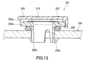
- the ventilation member 201 disclosed in Patent Document 2 includes a support body 202 on which the ventilation film 210 is disposed, and a cover fitted into the support body 202 so as to cover the ventilation film 210. And a component 203.
- a plurality of openings 203 a are formed in the upper part or the side part of the cover part 203.
- the leg portion 202b is inserted into the opening portion 250a of the housing 250 via the seal member 205, and the leg portion 202b inserted into the opening portion 250a is elastically deformed, whereby the ventilation member 201 is changed. It can be fixed to the housing 250.
- PTFE polytetrafluoroethylene
- the ventilation member 101 and the ventilation member 201 are not necessarily suitable for improving the air permeability because the ratio of the non-air-permeable members 102, 103, 202, 203, 205 is high.
- an object of the present invention is to provide a ventilation structure and a ventilation member suitable for improving the air permeability and reducing the manufacturing cost.
- the present invention A housing having an opening; A ventilation member formed of a porous resin and attached to the housing so as to cover the opening, At least one selected from the wall material, the projecting portion, and the ventilation member is provided on the side surface facing the opening of the wall material of the housing or the side surface of the projecting portion provided on the outer peripheral surface of the wall material.
- a ventilation structure in which the ventilation member is mounted in an elastically deformed state.
- the present invention further provides another aspect thereof.
- a ventilation member attachable to the casing so as to cover the opening of the casing, A protrusion formed on a side surface facing the opening of the wall material of the housing or an outer peripheral surface of the wall material when formed on the housing so as to cover the opening.
- a ventilation member is provided that has a mounting surface that abuts on at least one selected from the wall material, the projecting portion, and the ventilation member in an elastically deformed state on a side surface of the portion.
- the ventilation member according to the present invention has a portion to be attached to a part (the side surface) of the casing used for attachment, which is formed of a porous resin having air permeability as compared with the conventional ventilation member.
- a ventilation structure suitable for improving air permeability and reducing manufacturing costs.
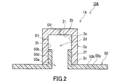
- FIG. 1 A ventilation member 1A according to the first embodiment of the present invention is shown in FIG. 1, and a ventilation structure 10A according to the first embodiment of the present invention is shown in FIG.
- the ventilation structure 10A includes a housing 50 having an opening 50a and a ventilation member 1A that is formed of a porous resin and is attached to the housing 50 so as to cover the opening 50a.
- the wall material 50g of the housing 50 separates the internal space and the external space of the housing 50.
- the opening 50a is a through hole that penetrates the wall material 50g and communicates the internal space of the housing 50 with the external space.
- the protrusion 50b of the housing 50 protrudes in a cylindrical shape on the outer peripheral surface 50h side of the wall member 50g at the peripheral edge of the opening 50a.
- the wall material 50g and the protrusion 50b are integrally formed of a non-breathable material.
- the ventilation member 1A is provided with a cylindrical recess 2d having a circular opening 2c, and has a side wall 2a that forms a side surface (inner peripheral surface) 2h of the recess 2d.
- the side wall 2a is mounted on the side surface (outer peripheral surface) 50d of the protrusion 50b in a state where at least one of the protrusion 50b and the side wall 2a is elastically deformed.
- the side wall portion 2a is moved to the outer peripheral side.
- the side wall portion 2a is attached to the side surface 50d in a state where an urging force is generated on the inner peripheral side, the inner peripheral surface 2h of the side wall portion 2a and the outer peripheral surface 50d of the protruding portion 50b are in close contact with each other. For this reason, intrusion of water or the like from the external space of the housing 50 to the internal space can be prevented.
- the inner peripheral surface 2h and the outer peripheral surface 50d are in direct contact with each other.
- the present invention is not limited to this, and the entry of water or the like may be more reliably prevented by interposing an adhesive between the protruding portion 50b and the side wall portion 2a.
- the ventilation member 1A may be mounted in a deformed state.
- the ventilation member 1A is a bottomed cylindrical member in which the bottom wall portion 2b and the side wall portion 2a are integrally formed. Note that the shape of the ventilation member 1A is not limited to this, and for example, the upper part of the side wall 2a that does not contact the protrusion 50b may be inclined and the cross section thereof may be an inverted V shape. . In this case, the bottom wall 2b does not exist.
- the side surface (inner peripheral surface) 2h of the side wall portion 2a has a non-mounting surface 2e that does not contact the side surface (outer peripheral surface) 50d of the protruding portion 50b and a mounting surface 2f that contacts the side surface 50d.
- the non-mounting surface 2e is located above the side wall portion 2a in the drawing and is continuous with the disc-shaped bottom wall portion 2b that forms the bottom surface 2i of the recess 2d.
- the mounting surface 2f is located below the side wall 2a in the figure and is connected to the opening 2c.
- the non-mounting surface 2e defines the area of the ventilation path that faces the inner space of the housing 50 in the ventilation member 1A together with the bottom surface 2i. The presence of the non-mounting surface 2e improves the air permeability of the ventilation structure 10A as compared to the case where the entire side surface 2h of the side wall 2a is the mounting surface 2f.
- the ventilation member 1A Since the ventilation member 1A is formed of a porous resin, the inside functions as a ventilation path.
- the bottom wall 2b and the side wall 2a can ventilate between the inner peripheral surface facing the recess 2d and the outer peripheral surface opposite to the inner peripheral surface.
- the bottom wall portion 2b of the ventilation member 1A and the upper side wall portion 2a forming the non-mounting surface 2e function as a main ventilation path.
- the lower side wall portion 2a forming the mounting surface 2f also functions as a slightly long ventilation path that leads to the non-mounting surface 2e.
- FIG. 3 and 4 illustrate another ventilation structure using the same ventilation member as the ventilation member 1A.
- the outer peripheral surface 2g of the side wall 2a of the ventilation member 1B is in contact with the inner peripheral surface 50e of the protrusion 50b of the housing 50.
- a protruding portion 50 c protruding in a cylindrical shape on the outer peripheral surface 50 h of the housing 50 is provided on the outer peripheral side of the protruding portion 50 b.
- the ventilation member 1C is mounted by inserting the side wall portion 2a between the outer peripheral surface 50d of the protruding portion 50b and the inner peripheral surface 50e of the protruding portion 50c.
- a ventilation member 1C is prepared in which the thickness of the side wall portion 2a is slightly larger than the distance between the side surface 50d of the protruding portion 50b and the side surface 50e of the protruding portion 50c, and the side wall portion 2a is provided between the protruding portion 50b and the protruding portion 50c.
- the side wall portion 2a is attached between the side surface 50d and the side surface 50e.
- the lower end surface of the side wall 2a is in contact with the outer peripheral surface 50h of the housing 50.
- the ventilation structure in a state where the lower end surface of the side wall 2a is separated from the outer peripheral surface 50h of the housing 50. It is good.
- the ventilation member 1A preferably has a side wall 2a and a bottom wall 2b integrally formed of a porous resin. Accordingly, the side wall portion 2a and the bottom wall portion 2b are each a part of one member formed of a porous resin, and are not individually molded and joined members. However, another member may be additionally joined to the ventilation member 1A.
- the porous resin forming the ventilation member 1A is a porous molded body formed by binding resin fine particles to each other.
- the porosity of the porous resin molded body is preferably 20 to 90%.
- Ultra high molecular weight polyethylene is preferable.
- “ultra high molecular weight polyethylene” refers to polyethylene having an average molecular weight of 500,000 or more.
- the average molecular weight of ultra high molecular weight polyethylene is usually in the range of 2 to 10 million.
- An average molecular weight can be measured by the method prescribed
- ultra high molecular weight polyethylene is abbreviated as “UHMWPE (Ultra High High Molecular Weight Polyethylene)”.
- the UHMWPE porous resin molding can be manufactured from a sintered body of UHMWPE powder.
- the sintered body of UHMWPE powder is obtained by sintering UHMWPE powder (for example, average particle size of 30 to 200 ⁇ m) filled in a mold at a temperature near the melting point of UHMWPE (for example, 130 to 160 ° C.).
- the porosity of the obtained UHMWPE porous resin molding is in the range of 20 to 90%.
- the surface of the ventilation member 1A may be subjected to a liquid repellent treatment.
- the liquid repellent treatment can be performed by a known method.
- the liquid repellent used for the liquid repellent treatment is not particularly limited, and is typically a material containing a polymer having a perfluoroalkyl group.
- the method of forming a film containing a polymer having a perfluoroalkyl group includes air spray method, electrostatic spray method, dip coating method, spin coating method, roll coating method (including kiss coating method and gravure coating method), curtain flow.
- Examples thereof include coating of a polymer solution or dispersion having a perfluoroalkyl group by a coating method, an impregnation method or the like, a film forming method by an electrodeposition coating method or a plasma polymerization method, and the like.
- the thickness of the ventilation member 1A (the thickness D1 of the side wall 2a and the thickness D2 of the bottom wall 2b) is desirably 0.2 mm or more and 20 mm or less, and is 0.3 mm or more and 10 mm or less. It is preferably 0.5 mm or more and 10 mm or less, more preferably 1 mm or more and 5 mm or less, and particularly preferably 1.5 mm or more and 5 mm or less.
- the thickness D1 of the side wall 2a is the same as the thickness D2 of the bottom wall 2b, but the thickness D1 and the thickness D2 may be different from each other.
- the ventilation structure 10D includes a housing 50 having an opening 50a and a ventilation member 1D that is formed of a porous resin and is attached to the housing 50 so as to cover the opening 50a.
- the ventilation member 1D is mounted on the side surface 50f facing the opening 50a of the wall member 50g of the housing 50 in a state where at least one of the wall member 50g and the ventilation member 1D is elastically deformed.
- the ventilation member 1D has a columnar mounting portion 3a fitted into the circular opening 50a and a columnar flange 3b having an outer diameter larger than the outer diameter of the mounting portion 3a.
- the mounting portion 3a is mounted on the side surface 50f facing the opening 50a in a state where at least one of the wall material 50g and the mounting portion 3a is elastically deformed.
- a ventilation member 1D having an outer diameter of the mounting portion 3a slightly larger than the inner diameter of the opening 50a is prepared, and the mounting portion 3a is press-fitted into the opening 50a, thereby mounting the mounting portion 3a on the side surface 50f.
- the ventilation member 1D is mounted in a state of being elastically deformed on the inner peripheral side.
- the ventilation member 1D may be attached.
- the side surface of the mounting portion 3a and the side surface of the wall material 50g are brought into close contact with each other by the urging force accompanying the elastic deformation, and intrusion of water or the like from the external space is prevented.
- an adhesive may be interposed.
- the side surface of the mounting portion 3a has a mounting surface 3h that contacts the side surface 50f and a non-mounting surface 3i that does not contact the side surface 50f when the housing 50 is mounted so as to cover the opening 50a.
- the mounting surface 3h is located above the mounting portion 3a in the figure and is connected to the lower end surface of the flange portion 3b.
- the non-mounting surface 3 i is located below the mounting portion 3 a in the drawing and is connected to the lower end surface of the mounting portion 3 a that projects into the internal space of the housing 50.
- the lower end surface of the flange portion 3b is mounted so as to be in contact with the outer peripheral surface 50h of the housing 50.
- the mounting part 3a and the collar part 3b are cylindrical solid members.
- the outer diameter of the flange portion 3b is larger than the outer diameter of the mounting portion 3a, and the central axis of the flange portion 3b is the same as the central axis of the mounting portion 3a.
- the length of the mounting portion 3a may be shortened so that the non-mounting surface 3i does not exist so that the mounting portion 3a does not protrude into the internal space of the housing 50.
- a seal member such as an O-ring may be interposed between the lower end surface of the flange portion 3b and the outer peripheral surface 50h of the housing 50.
- the ventilation member 1D Since the ventilation member 1D is formed of a porous resin, the inside functions as a ventilation path.
- the inside of the mounting portion 3a and the flange portion 3b can be ventilated in all directions.
- the mounting portion 3a and the flange portion 3b above it function as a main ventilation path. However, it functions as a slightly long ventilation path connected to the side surface of the outer edge side of the flange 3b.
- the thickness D3 in the mounting direction of the ventilation member 1D is desirably 5 mm or more and 50 mm or less, and preferably 8 mm or more and 30 mm or less. Further, the thickness D4 in the mounting direction of the flange portion 3b is desirably 0.2 mm or more and 10 mm or less, and preferably 0.3 mm or more and 5 mm or less.
- the ventilation member 1D is integrally formed of a porous resin that allows at least the mounting portion 3a and the flange portion 3b to vent. Other members may be additionally joined to the ventilation member 1D.
- the porous resin is, for example, a porous molded body formed by binding ultra-high molecular weight polyethylene fine particles to each other.
- the surface of the ventilation member 1D is preferably subjected to a liquid repellent treatment.
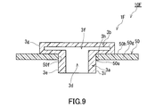
- the mounting portion 3a and the flange portion 3b are solid members. However, as shown in FIGS. 7 to 9, the mounting portion 3a and the flange portion 3b are hollow members having through holes and recesses. Also good. Although not shown, only the mounting portion 3a may be a hollow member having a recess.
- the mounting portion 3a of the ventilation member 1E has a through-hole 3d and a first wall 3e formed so as to surround the through-hole 3d.
- the first wall 3e can ventilate between the inner peripheral surface facing the through hole 3d and the outer peripheral surface opposite to the inner peripheral surface.
- the flange 3b has a recess 3f communicating with the through-hole 3d, and has a second wall 3g formed so as to surround the recess 3f.
- the second wall 3g can ventilate between the inner peripheral surface facing the recess 3f and the outer peripheral surface on the opposite side of the inner peripheral surface.
- the through hole 3d is a through hole formed so as to penetrate in a cylindrical shape
- the concave portion 3f is a concave portion formed so as to be recessed in a cylindrical shape.
- the central axes of the through hole 3d and the recess 3f are the same as the central axes of the mounting portion 3a and the flange 3b, and the inner diameter of the recess 3f is the same as the inner diameter of the through hole 3d.
- the through holes 3d and the recesses 3f may be formed by injection molding or may be formed by cutting.
- the shape of the recess 3f is changed in the flange portion 3b of the ventilation member 1F. Specifically, the recess 3f expands in the radial direction so that the inner diameter of the recess 3f is larger than the inner diameter of the through hole 3d.
- Example 1 The UHMWPE porous resin molded body (porosity 37%) is formed in the shape of the ventilation member shown in FIGS. 1 and 2, the outer diameter of the ventilation member is 12 mm, the inner diameter of the recess is 8 mm, and the ventilation member is attached in the mounting direction. Cutting was performed so that the length was 12 mm, the length in the mounting direction of the recess was 10 mm, the thickness of the side wall portion was 2 mm, and the thickness of the bottom wall portion was 2 mm to obtain a ventilation member.
- Teflon (registered trademark) AF2400 manufactured by DuPont
- a diluent Fluorinert (registered trademark) FC-43 (manufactured by Sumitomo 3M)
- FC-43 manufactured by Sumitomo 3M
- the vent member is elastically deformed and attached to the protruding portion of the ECU box in the state shown in FIG.
- the ventilation volume of the ventilation member (the sum of the volume of the side wall portion and the volume of the bottom wall portion) was 855 cm 3
- the air flow rate per 1 kPa differential pressure measured by the flow meter was 3878 cm 3 / kPa / min. It was.
- the maximum differential pressure when the temperature of the ECU box was changed from ⁇ 40 ° C. to 125 ° C. over 1 hour was 0.180 kPa.
- Example 2 In the UHMWPE porous resin molded body, the outer diameter of the flange portion is 20 mm, the outer diameter of the mounting portion is 10.6 mm, and the thickness in the mounting direction of the flange portion is such that the shape of the ventilation member shown in FIGS. Cutting was performed so that the thickness in the mounting direction of the mounting portion was 3 mm, the thickness in the mounting direction of the ventilation member was 8 mm, and the ventilation member was obtained. Further, Teflon (registered trademark) AF2400 was diluted with a diluent (Fluorinert (registered trademark) FC-43) to a concentration of 3.0% by weight to prepare a liquid repellent treatment solution.
- a diluent Feluorinert (registered trademark) FC-43
- This liquid-repellent treatment liquid was kept at 20 ° C., and the ventilation member was immersed therein for about 5 seconds, and then was left to stand at room temperature for about 1 hour to dry, thereby obtaining a ventilation member having liquid repellency.
- an ECU box (volume 60000 cm 3 ) having the shape of the housing shown in FIG. 6 and having an opening with an inner diameter of 10.4 mm was prepared. The ventilation member was elastically deformed and attached to the opening of the ECU box in the state shown in FIG.
- the ventilation volume of the ventilation member (the sum of the volume of the mounting portion and the volume of the collar portion) was 1335 cm 3 , and the amount of ventilation per differential pressure of 1 kPa was 6000 cm 3 / kPa / min.
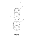
- a TEMISH (registered trademark) cap seal (C2-NTF9208-L01) manufactured by Nitto Denko Corporation shown in FIG. 11 was prepared as a ventilation member.
- an ECU box (capacity 60000 cm 3 ) having the shape of the casing shown in FIG. 11 and formed so that the outer diameter of the protruding portion is 8.5 mm and the inner diameter is 4.5 mm was prepared.
- the tubular member of the ventilation member was attached to the protruding portion of the ECU box in the state shown in FIG. 11 while being elastically deformed.
- the ventilation volume of the ventilation member (total volume of the ventilation path) was 5.72 cm 3
- the ventilation volume per differential pressure of 1 kPa was 1500 cm 3 / kPa / min.
- the maximum differential pressure when the temperature of the ECU box was changed from ⁇ 40 ° C. to 125 ° C. over 1 hour was 0.46 kPa.
- TEMISH registered trademark
- Z3-NTF210SE manufactured by Nitto Denko Corporation shown in FIG. 13
- ECU box volume: 60000 cm 3
- the leg portion of the ventilation member was attached to the opening of the ECU box in the state shown in FIG. 13 while being elastically deformed.
- the ventilation volume of the ventilation member was 11.3 cm 3
- the ventilation volume per differential pressure of 1 kPa was 100 cm 3 / kPa / min.
- the maximum differential pressure when the temperature of the ECU box was changed from ⁇ 40 ° C. to 125 ° C. over 1 hour was 5.88 kPa.
- the waterproof ventilation member according to the present invention can be applied to other than the body of an automobile electrical component.
- the present invention can be applied to a housing of an OA device, a home appliance, or a medical device.
Landscapes
- Engineering & Computer Science (AREA)
- Microelectronics & Electronic Packaging (AREA)
- General Engineering & Computer Science (AREA)
- Chemical & Material Sciences (AREA)
- Combustion & Propulsion (AREA)
- Mechanical Engineering (AREA)
- Physics & Mathematics (AREA)
- Thermal Sciences (AREA)
- Arrangement Of Elements, Cooling, Sealing, Or The Like Of Lighting Devices (AREA)
- Casings For Electric Apparatus (AREA)
- Non-Portable Lighting Devices Or Systems Thereof (AREA)
- Filtering Of Dispersed Particles In Gases (AREA)
Abstract
Description
開口部を有する筐体と、
多孔質樹脂により形成され、前記開口部を覆うように前記筐体に装着されている通気部材と、を備え、
前記筐体の壁材の前記開口部に面する側面、又は前記壁材の外周面に設けられた突出部の側面に、前記壁材、前記突出部及び前記通気部材から選ばれる少なくとも1つを弾性変形させた状態で前記通気部材が装着されている、通気構造を提供する。
筐体の開口部を覆うように前記筐体に装着可能な通気部材であって、
多孔質樹脂により形成され、前記開口部を覆うように前記筐体に装着したときに、前記筐体の壁材の前記開口部に面する側面、又は前記壁材の外周面に設けられた突出部の側面に、前記壁材、前記突出部及び前記通気部材から選ばれる少なくとも1つを弾性変形させた状態で当接する装着面を有する、通気部材を提供する。
本発明の第1実施形態に係る通気部材1Aを図1に示し、本発明の第1実施形態に係る通気構造10Aを図2に示す。通気構造10Aは、開口部50aを有する筐体50と、多孔質樹脂により形成され、開口部50aを覆うように筐体50に装着されている通気部材1Aと、を備えている。筐体50の壁材50gは、筐体50の内部空間と外部空間とを隔てている。開口部50aは、壁材50gを貫通し、筐体50の内部空間と外部空間とを連通する貫通孔である。筐体50の突出部50bは、開口部50aの周縁部において壁材50gの外周面50h側に円筒状に突出している。壁材50gと突出部50bとは、非通気性の材料により一体的に形成されている。
次に、図5及び図6を参照して、本発明の第2実施形態に係る通気部材1D及び通気構造10Dを説明する。
UHMWPE多孔質樹脂成形体(気孔率37%)を、図1及び図2に示す通気部材の形状になるように、通気部材の外径が12mm、凹部の内径が8mm、通気部材の装着方向の長さが12mm、凹部の装着方向の長さが10mm、側壁部の厚みが2mm、底壁部の厚みが2mmとなるように切削加工し、通気部材を得た。また、テフロン(登録商標)AF2400(デュポン社製)を3.0重量%の濃度となるように希釈剤(フロリナート(登録商標)FC-43(住友スリーエム社製))で希釈して撥液処理液を調製した。この撥液処理液を20℃に保ち、この中に通気部材を約5秒間浸し、その後にこれを常温で約1時間放置して乾燥させて、撥液性を備えた通気部材を得た。また、図2に示す筐体の形状であって、突出部の外径が8.5mm、内径が4.5mmとなるように形成したECUボックス(容積60000cm3)を準備した。この通気部材を弾性変形させた状態でECUボックスの突出部に図2の状態で取り付けた。このときの通気部材の通気体積(側壁部の体積と底壁部の体積との総和)は855cm3であり、流量計により測定した差圧1kPa当たりの通気量は3878cm3/kPa/minであった。このECUボックスを1時間かけて-40℃から125℃に温度変化させたときの最大差圧は0.180kPaであった。
UHMWPE多孔質樹脂成形体を、図5及び図6に示す通気部材の形状になるように、鍔部の外径が20mm、装着部の外径が10.6mm、鍔部の装着方向の厚みが3mm、装着部の装着方向の厚みが5mm、通気部材の装着方向の厚みが8mmとなるように切削加工し、通気部材を得た。また、テフロン(登録商標)AF2400を3.0重量%の濃度となるように希釈剤(フロリナート(登録商標)FC-43)で希釈して撥液処理液を調製した。この撥液処理液を20℃に保ち、この中に通気部材を約5秒間浸し、その後にこれを常温で約1時間放置して乾燥させて、撥液性を備えた通気部材を得た。また、図6に示す筐体の形状であって、開口部の内径が10.4mmとなるように形成したECUボックス(容積60000cm3)を準備した。この通気部材を弾性変形させた状態でECUボックスの開口部に図6の状態で取り付けた。このときの通気部材の通気体積(装着部の体積と鍔部の体積との総和)は1335cm3であり、差圧1kPa当たりの通気量は6000cm3/kPa/minであった。このECUボックスを1時間かけて-40℃から125℃に温度変化させたときの最大差圧は0.117kPaであった。
通気部材として図11に示す日東電工株式会社製のTEMISH(登録商標)キャップシール(C2-NTF9208-L01)を準備した。また、図11に示す筐体の形状であって、突出部の外径が8.5mm、内径が4.5mmとなるように形成したECUボックス(容積60000cm3)を準備した。この通気部材の筒状体を弾性変形させた状態でECUボックスの突出部に図11の状態で取り付けた。このときの通気部材の通気体積(通気経路の総体積)は5.72cm3であり、差圧1kPa当たりの通気量は1500cm3/kPa/minであった。このECUボックスを1時間かけて-40℃から125℃に温度変化させたときの最大差圧は0.46kPaであった。
通気部材として図13に示す日東電工株式会社製のTEMISH(登録商標)Z3-NTF210SEを準備した。また、図13に示す筐体の形状であって、開口部の内径が10.4mmとなるように形成したECUボックス(容積60000cm3)を準備した。この通気部材の脚部を弾性変形させた状態でECUボックスの開口部に図13の状態で取り付けた。このときの通気部材の通気体積(通気経路の総体積)は11.3cm3であり、差圧1kPa当たりの通気量は100cm3/kPa/minであった。このECUボックスを1時間かけて-40℃から125℃に温度変化させたときの最大差圧は5.88kPaであった。
Claims (14)
- 開口部を有する筐体と、
多孔質樹脂により形成され、前記開口部を覆うように前記筐体に装着されている通気部材と、を備え、
前記筐体の壁材の前記開口部に面する側面、又は前記壁材の外周面に設けられた突出部の側面に、前記壁材、前記突出部及び前記通気部材から選ばれる少なくとも1つを弾性変形させた状態で前記通気部材が装着されている、通気構造。 - 前記通気部材は、開口を有する凹部が設けられ、前記凹部の側面を形成する側壁部を有し、
前記突出部の前記側面に、前記突出部及び前記側壁部の少なくともいずれかを弾性変形させた状態で前記側壁部が装着されている、請求項1に記載の通気構造。 - 前記側壁部の側面が、前記突出部の前記側面に当接する装着面と、前記突出部の前記側面に当接しない非装着面と、を有する、請求項2に記載の通気構造。
- 前記通気部材は、前記開口部に嵌め込まれる装着部と、前記装着部と一体的に形成され前記装着部の外径より大きい外径を有する鍔部と、を有し、
前記開口部に面する前記側面に、前記壁材及び前記装着部の少なくともいずれかを弾性変形させた状態で前記装着部が装着されている、請求項1に記載の通気構造。 - 前記装着部は、
貫通孔を有し、前記貫通孔を囲むように形成され、前記貫通孔に面する内周面と前記内周面の反対側の外周面との間を通気可能である第1壁部、
を有し、
前記鍔部は、
前記貫通孔と連通する凹部を有し、前記凹部を囲むように形成され、前記凹部に面する内周面と前記内周面の反対側の外周面との間を通気可能である第2壁部、
を有している、請求項4に記載の通気構造。 - 前記通気部材の表面は、撥液処理されている、請求項1に記載の通気構造。
- 前記多孔質樹脂は、樹脂の微粒子が互いに結着して構成された多孔質成形体である、請求項1に記載の通気構造。
- 前記通気部材の厚みは、0.2mm以上20mm以下である、請求項1に記載の通気構造。
- 前記多孔質樹脂の気孔率は、20%以上90%以下である、請求項1に記載の通気構造。
- 筐体の開口部を覆うように前記筐体に装着可能な通気部材であって、
多孔質樹脂により形成され、前記開口部を覆うように前記筐体に装着したときに、前記筐体の壁材の前記開口部に面する側面、又は前記壁材の外周面に設けられた突出部の側面に、前記壁材、前記突出部及び前記通気部材から選ばれる少なくとも1つを弾性変形させた状態で当接する装着面を有する、通気部材。 - 開口を有する凹部が設けられ、前記凹部の側面を形成する側壁部を有し、
前記側壁部は、前記開口部を覆うように前記筐体に装着したときに、前記突出部の前記側面に、前記突出部及び前記側壁部の少なくともいずれかを弾性変形させた状態で当接する前記装着面を有する、請求項10に記載の通気部材。 - 前記開口部に嵌め込まれる装着部と、前記装着部と一体的に形成され前記装着部の外径より大きい外径を有する鍔部と、を有し、
前記装着部は、前記開口部を覆うように前記筐体に装着したときに、前記開口部に面する前記側面に、前記壁材及び前記装着部の少なくともいずれかを弾性変形させた状態で当接する前記装着面を有する、請求項10に記載の通気部材。 - 前記多孔質樹脂は、樹脂の微粒子が互いに結着して構成された多孔質成形体である、請求項10に記載の通気部材。
- 前記通気部材の厚みは、0.2mm以上20mm以下である、請求項10に記載の通気部材。
Priority Applications (4)
| Application Number | Priority Date | Filing Date | Title |
|---|---|---|---|
| EP14835089.5A EP3031509A4 (en) | 2013-08-09 | 2014-07-08 | Ventilation structure and ventilation member |
| KR1020167002766A KR102366647B1 (ko) | 2013-08-09 | 2014-07-08 | 통기 구조 및 통기 부재 |
| CN201480043925.2A CN105451857B (zh) | 2013-08-09 | 2014-07-08 | 通气构造及通气构件 |
| US14/903,504 US9861000B2 (en) | 2013-08-09 | 2014-07-08 | Ventilation structure and ventilation member |
Applications Claiming Priority (2)
| Application Number | Priority Date | Filing Date | Title |
|---|---|---|---|
| JP2013-167050 | 2013-08-09 | ||
| JP2013167050A JP2015033682A (ja) | 2013-08-09 | 2013-08-09 | 通気構造及び通気部材 |
Publications (1)
| Publication Number | Publication Date |
|---|---|
| WO2015019544A1 true WO2015019544A1 (ja) | 2015-02-12 |
Family
ID=52460907
Family Applications (1)
| Application Number | Title | Priority Date | Filing Date |
|---|---|---|---|
| PCT/JP2014/003621 WO2015019544A1 (ja) | 2013-08-09 | 2014-07-08 | 通気構造及び通気部材 |
Country Status (6)
| Country | Link |
|---|---|
| US (1) | US9861000B2 (ja) |
| EP (1) | EP3031509A4 (ja) |
| JP (1) | JP2015033682A (ja) |
| KR (1) | KR102366647B1 (ja) |
| CN (1) | CN105451857B (ja) |
| WO (1) | WO2015019544A1 (ja) |
Families Citing this family (8)
| Publication number | Priority date | Publication date | Assignee | Title |
|---|---|---|---|---|
| JP6390531B2 (ja) * | 2015-06-11 | 2018-09-19 | 株式会社デンソー | 収容部材、および、これを用いた車載用電子装置 |
| JP6721978B2 (ja) * | 2015-12-15 | 2020-07-15 | 日東電工株式会社 | 通気部材、ランプ |
| KR102452791B1 (ko) * | 2018-02-20 | 2022-10-11 | 주식회사 아모그린텍 | 통기성 캡 |
| JP7446233B2 (ja) | 2018-10-11 | 2024-03-08 | 日東電工株式会社 | 通気筐体 |
| DE112019005103T5 (de) | 2018-10-11 | 2021-07-08 | Nitto Denko Corporation | Belüftungsanordnung und Belüftungsgehäuse |
| US11420816B2 (en) | 2019-03-25 | 2022-08-23 | Donaldson Company, Inc. | Air reservoir assembly for a submergible enclosure |
| NL2022953B1 (nl) * | 2019-04-16 | 2020-10-26 | Qos Group B V | Een filter voor een ontluchtingsopening van een container |
| CA3167872A1 (en) * | 2020-01-14 | 2021-07-22 | Nitto Denko Corporation | Ventilation component |
Citations (9)
| Publication number | Priority date | Publication date | Assignee | Title |
|---|---|---|---|---|
| JPS4317679Y1 (ja) * | 1965-04-23 | 1968-07-22 | ||
| JPS51137496U (ja) * | 1975-04-30 | 1976-11-06 | ||
| JPS63186432U (ja) * | 1987-05-26 | 1988-11-30 | ||
| JPH03286489A (ja) * | 1990-03-31 | 1991-12-17 | Ricoh Co Ltd | 空冷方式情報処理システムユニツト装置 |
| JP2000205098A (ja) * | 1999-01-19 | 2000-07-25 | Ngk Spark Plug Co Ltd | グロ―プラグの通電制御ユニット |
| JP2001114339A (ja) * | 1999-10-20 | 2001-04-24 | Morinaga Milk Ind Co Ltd | 無菌培地包装体 |
| JP2006297200A (ja) * | 2005-04-15 | 2006-11-02 | Nitto Denko Corp | 脱気装置 |
| JP2007087929A (ja) | 2005-08-24 | 2007-04-05 | Nitto Denko Corp | 通気部材 |
| JP2007087666A (ja) | 2005-09-20 | 2007-04-05 | Nitto Denko Corp | 通気部材及び通気構造 |
Family Cites Families (15)
| Publication number | Priority date | Publication date | Assignee | Title |
|---|---|---|---|---|
| JPS4872151U (ja) * | 1971-12-11 | 1973-09-10 | ||
| JPS51137496A (en) | 1975-05-23 | 1976-11-27 | Sadao Yabuno | Lottery register |
| DE3311252A1 (de) | 1983-03-28 | 1984-10-04 | Joachim Dr.-Ing. 8070 Ingolstadt Hess | Kunststoffgehaeuse |
| JPS63172195U (ja) * | 1987-04-30 | 1988-11-09 | ||
| JPH09166340A (ja) * | 1995-12-14 | 1997-06-24 | Kaoru Sato | 換気装置 |
| JP4043674B2 (ja) * | 1999-11-18 | 2008-02-06 | 日東電工株式会社 | 通気キャップおよびそれを用いた屋外用ランプ,自動車用ランプならびに自動車用電装部品 |
| JP4555217B2 (ja) * | 2004-12-07 | 2010-09-29 | 日東電工株式会社 | 通気部材とこれを用いた通気筐体および電装部品 |
| DE602005015489D1 (de) * | 2004-12-07 | 2009-08-27 | Nitto Denko Corp | Durchlässiges glied, das durchlässige glied verwendendes durchlässiges gehäuse und elektrisches teil |
| JP4953663B2 (ja) * | 2006-03-02 | 2012-06-13 | 日東電工株式会社 | 通気部材および通気構造 |
| US20090107090A1 (en) * | 2007-10-31 | 2009-04-30 | Shawn Keel | Quick Connect Air Fitting with Integral Filter |
| WO2010081081A2 (en) | 2009-01-09 | 2010-07-15 | Porex Corporation | Relief vent for a hot fill fluid container |
| US20110297698A1 (en) | 2010-06-03 | 2011-12-08 | Casper Chiang | Vented bottle |
| JP4913239B2 (ja) * | 2010-11-12 | 2012-04-11 | 日東電工株式会社 | 通気部材とこれを用いた通気筐体 |
| JP5746559B2 (ja) * | 2011-05-19 | 2015-07-08 | 日東電工株式会社 | 通気構造 |
| CN202733854U (zh) * | 2012-05-30 | 2013-02-13 | 长城汽车股份有限公司 | 一种车灯通气结构 |
-
2013
- 2013-08-09 JP JP2013167050A patent/JP2015033682A/ja active Pending
-
2014
- 2014-07-08 KR KR1020167002766A patent/KR102366647B1/ko active IP Right Grant
- 2014-07-08 US US14/903,504 patent/US9861000B2/en active Active
- 2014-07-08 EP EP14835089.5A patent/EP3031509A4/en not_active Withdrawn
- 2014-07-08 WO PCT/JP2014/003621 patent/WO2015019544A1/ja active Application Filing
- 2014-07-08 CN CN201480043925.2A patent/CN105451857B/zh active Active
Patent Citations (9)
| Publication number | Priority date | Publication date | Assignee | Title |
|---|---|---|---|---|
| JPS4317679Y1 (ja) * | 1965-04-23 | 1968-07-22 | ||
| JPS51137496U (ja) * | 1975-04-30 | 1976-11-06 | ||
| JPS63186432U (ja) * | 1987-05-26 | 1988-11-30 | ||
| JPH03286489A (ja) * | 1990-03-31 | 1991-12-17 | Ricoh Co Ltd | 空冷方式情報処理システムユニツト装置 |
| JP2000205098A (ja) * | 1999-01-19 | 2000-07-25 | Ngk Spark Plug Co Ltd | グロ―プラグの通電制御ユニット |
| JP2001114339A (ja) * | 1999-10-20 | 2001-04-24 | Morinaga Milk Ind Co Ltd | 無菌培地包装体 |
| JP2006297200A (ja) * | 2005-04-15 | 2006-11-02 | Nitto Denko Corp | 脱気装置 |
| JP2007087929A (ja) | 2005-08-24 | 2007-04-05 | Nitto Denko Corp | 通気部材 |
| JP2007087666A (ja) | 2005-09-20 | 2007-04-05 | Nitto Denko Corp | 通気部材及び通気構造 |
Non-Patent Citations (1)
| Title |
|---|
| See also references of EP3031509A4 |
Also Published As
| Publication number | Publication date |
|---|---|
| JP2015033682A (ja) | 2015-02-19 |
| CN105451857B (zh) | 2017-04-12 |
| CN105451857A (zh) | 2016-03-30 |
| KR102366647B1 (ko) | 2022-02-22 |
| KR20160040546A (ko) | 2016-04-14 |
| EP3031509A1 (en) | 2016-06-15 |
| EP3031509A4 (en) | 2017-04-12 |
| US9861000B2 (en) | 2018-01-02 |
| US20160174397A1 (en) | 2016-06-16 |
Similar Documents
| Publication | Publication Date | Title |
|---|---|---|
| WO2015019544A1 (ja) | 通気構造及び通気部材 | |
| US9120059B2 (en) | Ventilation unit | |
| US9120060B2 (en) | Ventilation unit | |
| US9636616B2 (en) | Water-proof air-permeable filter and use of the same | |
| CN104080305B (zh) | 防水通气结构、防水通气构件及防水通气膜 | |
| KR102020681B1 (ko) | 통기 구조 | |
| EP2733418B1 (en) | Ventilation device comprising a housing and a ventilation member | |
| CN109417856B (zh) | 通风部 | |
| EP1884695A1 (en) | Gas permeable member and gas permeable casing using the same | |
| JP6132615B2 (ja) | 通気部材 | |
| US20150306529A1 (en) | Ventilation member | |
| WO2014068902A1 (ja) | 通気部材 | |
| JP2012069644A (ja) | 電解コンデンサ | |
| JP6762630B1 (ja) | 通気防水構造体 | |
| WO2015019545A1 (ja) | 通気部材 | |
| JP2017029891A (ja) | 除湿機器および機器 | |
| JP6121210B2 (ja) | 通気部材 | |
| CN211702388U (zh) | 传感器封装结构及电子设备 |
Legal Events
| Date | Code | Title | Description |
|---|---|---|---|
| WWE | Wipo information: entry into national phase |
Ref document number: 201480043925.2 Country of ref document: CN |
|
| 121 | Ep: the epo has been informed by wipo that ep was designated in this application |
Ref document number: 14835089 Country of ref document: EP Kind code of ref document: A1 |
|
| WWE | Wipo information: entry into national phase |
Ref document number: 14903504 Country of ref document: US |
|
| ENP | Entry into the national phase |
Ref document number: 20167002766 Country of ref document: KR Kind code of ref document: A |
|
| NENP | Non-entry into the national phase |
Ref country code: DE |
|
| WWE | Wipo information: entry into national phase |
Ref document number: 2014835089 Country of ref document: EP |